jerguson®/jacoby-tarbox® eductors for pumping liquids · i how to size liquid motive eductors for...
TRANSCRIPT
I for
Principles of Operationfor Puinping LIquids
Eductors operate on the basic principles of flow dynamics. This involves taking a high pressure motive stream and accelerating it through a tapered nozzle to increase the velocity of the fluid (gas or liquid) that is put through the nozzle. This fluid is then carried on through a secondary chamber where the ftiction between the molecules of it and a secondary fluid (generally referred to as the suction fluid) causes this fluid to be pumped. These fluids are intimately mixed together and discharged from the eductor.
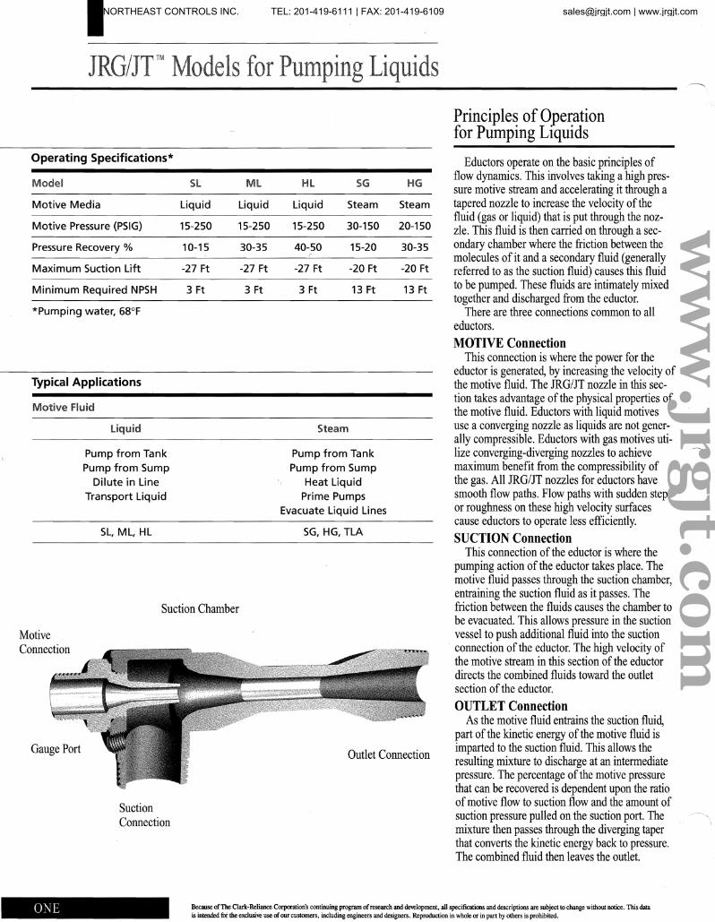
There are three connections common to all eductors. MOTIVE Connection
This connection is where the power for the eductor is generated, by increasing the velocity of the motive fluid. The JRG/JT nozzle in this section takes advantage of the physical properties of the motive fluid. Eductors with liquid motives use a converging nozzle as liquids are not generally compressible. Eductors with gas motives utilize converging-diverging nozzles to achieve maximum benefit from the compressibility of the gas. All JRG/JT nozzles for eductors have smooth flow paths. Flow paths with sudden steps or roughness on these high velocity surfaces cause eductors to operate less efficiently. SUCTION Connection
This connection of the eductor is where the pumping action of the eductor takes place. The motive fluid passes through the suction chamber, entraining the suction fluid as it passes. The friction between the fluids causes the chamber to be evacuated. This allows pressure in the suction vessel to push additional fluid into the suction connection of the eductor. The high velocity of the motive stream in this section of the eductor directs the combined fluids toward the outlet section of the eductor. OUTLET Connection
As the motive fluid entrains tlle suction fluid, part of the kinetic energy of the motive fluid is imparted to the suction fluid. This allows the resulting mixture to discharge at an intermediate pressure. The percentage of the motive pressure that can be recovered is dependent upon the ratio ofmotive flow to suction flow and the amount of suction pressure pulled on the suction port. The mixture then passes through the diverging taper that converts the kinetic energy back to pressure. The combined fluid then leaves the outlet.
Operating Specifications*
Model
Motive Media
Motive Pressure (PSIG)
Pressure Recovery %
Maximum Suction Lift
Minimum Required NPSH
*Pumping water, 68°F
Typical Applications
Motive Fluid
Pump from Tank Pump from Sump
Dilute in Line Transport Liquid
SL, ML, HL
Sl
Liquid
15-250
10-15
-27 Ft
3 Ft
Ml
Liquid
15-250
30-35
-27 Ft
3 Ft
Hl
Liquid
15-250
40-50
-27 Ft
3 Ft
SG
Steam
30-150
15-20
-20 Ft
13 Ft
Pump from Tank Pump from Sump
Heat Liquid Prime Pumps
Evacuate Liquid Lines
SG, HG, TLA
HG
Steam
20-150
30-35
-20 Ft
13 Ft
Suction Chamber
Motive Connection
Gauge Port Outlet Connection
Suction Connection
Because of The Clark-Reliance CorfXlTation's continuing program of research and de\elopment, al1 specifications and descriptions are subject to change without notice. This data is intended fot the exclusive use of our customers, including engineers and designers. Reproduction in whole or in part by others is prohibited.
ww
w.jrgjt.com
NORTHEAST CONTROLS INC. TEL: 201-419-6111 | FAX: 201-419-6109 [email protected] | www.jrgjt.com
I Ilow Motive
Using Liquid Motives to Pump Liquid Suction Fluids
To determine the correct eductor for a specific application, follow the steps in this section, using the performance tables (pages 3-4) provided to achieve your desired results. (NOTE: All JRG/JT tables use the 1-1/2 inch unit as the standard, and eductors are sized using a Sizing Factor (S.P') based on this standard unit.)
Step 1 Find the suction lift* or head (Hs) that is equal to or greater than your desired lift. If your lift is between two of the lifts on the table, use an average of the two. You can also or use the calculated result from the NPSH formula found on page 5 of this manual. Using the NPSH number will correct for temperature variations and friction losses, resulting in a more accurate value.
Step 2 Find the outlet head** (Ho) equal to or greater than your actual outlet head. It is important to include friction losses into the desired outlet head. (Be certain that friction losses in the outlet line are calculated using the combined rate of both the motive and the suction flows.) It is important that the outlet line from the eductor be as large or larger than the outlet connection.
Step 3 Find the motive pressure (Pm)." Locate the motive pressure from the table that is closest to or lower than your actual motive pressure. The flow specified represents the Tabulated Suction Flow for each of the different models of eductors. To determine the size of eductor needed, first use the following formula to determine the Desired Sizing Factor (S.P') Do this for each of the models. D; d S F Desired Suction Flow
eme .. Tabulated Suction Flow
If a standard unit is being used, pick the size unit that has a Tabulated S.P. (page 7) equal to or greater than the Desired S.P.
If an exact match is desired, consult your Jerguson/Jacoby-Tarbox representative or the factory.
Step 4 Calculate the amOlmt ofmotive flow used by multiplying the Qm and Qs found in the tables by the Tabulated S.P. obtained in Step 3. Do this for each ofthe models of eductors.
Step 5 Select the unit from Steps 1-4 that best meets the motive and suction parameters of the specific application. If a turndown ratio*** of greater than 35% is needed, then choose two or more eductors that have the correct turndown ratio and operate these units in parallel.
In some cases, the unit chosen will have the greatest suction flow while consuming as little motive fluid as possible. This is generally true for pumping applications. In other applications, such as the dilution of chemicals, the motive flow should be as high as possible: while the suction flow will be low. In this case, the motive flow should be matched to the desired motive flow and the suction port should be throttled to achieve the desired dilution rate. As a general rule in dilution applications, the HL is the best unit to choose.
In all cases, the correct unit is the one that matches your desired range of motive-to-suction flows the closest.
Correcting for Non-Water Fluid Specifications
The performance specifications for JRG/JT eductors are based on using water" with a specific gravity of 1.0 and a viscosity of I Centipoise. Fluids with differing viscosities or specific gravities need to be corrected to water, to obtain accurate performance estimates.
Viscosity is the measure of the internal resistance of a fluid to flow. This should be taken into consideration in most pressure drop and flow calculations within a given system. When used with JRG/JT eductors, fluids with viscosities ofless than 100 Cpo have a negligible effect. Viscosities ofup to 500 Cpo can be used with only small corrections. For higher viscosities (applications above 500 Cp.), we suggest that you work
with your trained representative or the applications personnel at the factory. Eductors can be used with viscosities over 500 Cpo with calculated adjustments. The effects of viscosity on the pressure drops in the line leading to the eductor must be calculated separately.
Specific gravity is the measure of the weight per volume of a liquid. The performance data for eductors is based on water having a specific gravity of 1.0; other specific gravities will require that adjustments be made to the performance table value of the eductors. See the topics that follow for specifics on how to make these adjustments.
Motive Flow Adjustments The motive flow is the amount of liquid
used to power the eductor. To adjust the value from the performance table for specific gravity (Sg) of the motive fluid: Multiply the motive flow in the performance chart by the square root of(lISg).
Example:
50 GPM Tabulated Flow adjusted for a Specific Gravity of 1.3: 50 V(1I1.3) = 43.85 GPM Actual motive flow
Suction Flow Adjustments The best way to adjust for the specific
gravity or temperature effects of the suction fluid is to do the calculation for NPSH (see page 5 of this manual). If you desire a rough estimate of the specific gravity effect, multiply the suction lift by the specific gravity of the liquid. If the liquid temperature exceeds 100°F, you must use the NPSH calculation, or consult your representative or the factory.
Outlet Adjustments The outlet pressure of the eductor must be
adjusted for the specific gravity of the outlet liquid, particularly if the eductor is discharging to an elevated surface. If the outlet is being measured or controlled by a pressure regulator or valve, no adjustment is required. To calculate the actual outlet pressure, multiply the feet of elevation by the specific gravity of the outlet liquid.
•Suction Lift =vertical distance, Ft, from the suction connection to the surface of the suction liquid source. Minus =below the suction connection. "Outlet Head =vertical distance, Ft, from the outlet connection to the surface or the outlet liquid destination. Positive =above the outlet connection.
Use zero for equal to or below outlet connection. "'Turndown Ratio =(Max. suction flow minus min. suction t1ow) divided by max. suction l10w desired.
• Table data is based on water-like liquids at a temperature of68'F.
ww
w.jrgjt.com
NORTHEAST CONTROLS INC. TEL: 201-419-6111 | FAX: 201-419-6109 [email protected] | www.jrgjt.com
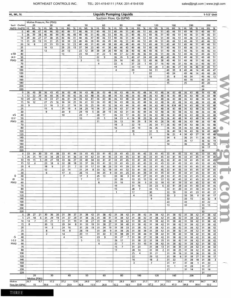
HL, ML, SL Liquids Pumping Liquids 1-1/2" Unit
Suction Flow, Qs (GPM) Motive Pressure, Pm (PSIG)
Suet Outlet 20 30 40 50 60 80 100 120 160 200 250 Hs(Ft) Ho(Ft) Hl Ml Sl Hl IVIl Sl Hl IVIl Sl Hl IVIl Sl Hl Ml Sl Hl Ml sl Hl Ml sl Hl IVIl Sl Hl Ml sl Hl Ml Sl Hl Ml Sl
0 40 46 47 40 46 50 40 46 51 40 46 51 40 46 51 40 46 51 40 46 51 40 46 51 40 46 51 40 46 51 40 46 51 5 36 39 38 40 46 44 40 46 49 40 46 51 40 46 51 40 46 51 40 46 51 40 46 51 40 46 51 40 46 51 40 46 51
10 29 30 27 37 38 35 40 46 41 40 46 47 40 46 51 40 46 51 40 46 51 40 46 51 40 46 51 40 46 51 40 46 51 15 21 20 13 31 31 25 39 39 33 40 46 39 40 46 45 40 46 51 40 46 51 40 46 51 40 46 51 40 46 51 40 46 51 20 14 8 25 23 13 34 32 23 40 40 31 40 46 38 40 46 48 40 46 51 40 46 51 40 46 51 40 46 51 40 46 51 25 19 13 29 25 13 37 34 23 40 41 30 40 46 43 40 46 51 40 46 51 40 46 51 40 46 51 40 46 51 30 13 24 13 23 12 39 39 34 20 40 46 36 40 46 46 40 46 51 40 46 51 40 46 51 40 46 51
+10 40 13 23 10 31 22 5 40 37 22 40 46 36 40 46 51 40 46 51 40 46 51 40 46 51 (4.3 50 13 22 9 36 26 9 40 41 24 40 46 40 40 46 51 40 46 51 40 46 51
PsIG) 60 3 13 29 16 40 32 12 40 46 28 40 46 51 40 46 51 40 46 51 70 4 22 6 37 23 1 40 37 16 40 46 37 40 46 51 40 46 51 80 19 33 13 40 28 3 40 46 27 40 46 46 40 46 51
100 4 20 34 11 40 39 8 40 46 14 40 46 47 120 7 22 40 24 40 46 14 40 46 29 140 10 35 8 40 34 40 46 13 160 26 40 19 40 35 180 15 35 40 20 200 40 220 34
0 36 40 39 36 43 45 36 43 48 36 43 48 36 43 48 36 43 48 36 43 48 36 43 48 36 43 48 36 43 48 36 43 48 5 32 32 29 36 40 36 36 43 42 36 43 48 36 43 48 36 43 48 36 43 48 36 43 48 36 43 48 36 43 48 36 43 48
10 24 22 16 33 33 27 36 41 34 36 43 41 36 43 46 36 43 48 36 43 48 36 43 48 36 43 48 36 43 48 36 43 48 15 16 12 27 25 16 36 34 25 36 41 33 36 43 40 36 43 48 36 43 48 36 43 48 36 43 48 36 43 48 36 43 48 20 9 21 16 3 31 27 16 36 35 25 36 43 32 36 43 44 36 43 48 36 43 48 36 434 48 36 43 48 36 43 48 25 15 6 25 19 4 34 29 16 36 37 24 36 43 37 36 43 48 36 43 48 36 43 48 36 43 48 36 43 48 30 9 20 9 29 19 5 36 29 15 36 43 31 36 43 44 36 43 48 36 43 48 36 43 48 36 43 48
+5 40 10 20 7 28 17 36 33 17 36 43 32 36 43 48 36 43 48 36 43 48 36 43 48 (2.2 50 10 20 5 34 23 4 36 38 20 36 43 36 36 43 48 36 43 48 36 43 48
PsIG) 60 11 26 13 36 29 8 36 43 26 36 43 48 36 43 48 36 43 48 70 19 3 32 19 36 34 11 36 43 44 36 43 48 36 43 48 80 16 29 10 36 26 36 43 34 36 43 48 36 43 48
100 2 18 32 9 36 43 14 36 43 36 36 43 48 120 5 21 36 21 4 36 43 27 36 43 48 140 9 34 6 36 31 11 36 43 36 160 24 36 17 36 42 19 180 14 36 36 30 10 200 36 17 220 36
0 33 34 30 33 41 38 33 41 44 33 41 45 33 41 45 33 41 45 33 41 45 33 41 45 33 41 45 33 41 45 33 41 45 5 26 25 19 33 34 28 33 41 36 33 41 42 33 41 45 33 41 45 33 41 45 33 41 45 33 41 45 33 41 45 33 41 45
10 19 15 5 29 27 18 33 36 27 33 40 34 33 41 41 33 41 45 33 41 45 33 41 45 33 41 45 33 41 45 33 41 45 15 12 4 23 18 6 32 28 18 33 37 26 33 41 33 33 41 45 33 41 45 33 41 45 33 41 45 33 41 45 33 41 45 20 4 18 9 27 21 7 33 31 17 33 38 26 33 41 39 33 41 45 33 41 45 33 41 45 33 41 45 33 41 . 45 25 12 22 14 31 24 8 33 32 18 33 41 32 33 41 43 33 41 45 33 41 45 33 41 45 33 41 45 30 6 17 4 26 15 34 25 9 33 41 25 33 41 39 33 41 45 33 41 45 33 41 45 33 41 45
0 40 7 17 3 25 13 33 30 3 33 41 27 33 41 29 33 41 45 33 41 45 33 41 45 (0 50 7 17 32 20 33 35 15 33 41 22 33 41 45 33 41 45 33 41 45
PSI G) 60 8 25 10 33 26 3 33 32 18 33 41 39 33 41 45 33 41 45 70 19 31 16 33 23 6 33 41 29 33 41 40 33 41 45 80 15 28 7 33 15 33 41 20 33 41 40 33 41 45
100 1 17 30 33 19 33 41 23 33 41 27 120 4 19 33 3 33 30 0 33 41 17 140 9 33 33 15 33 32 8 160 23 33 33 22 180 13 33 33 13 200 33 220 33
0 28 27 21 30 36 30 31 38 37 31 38 42 31 38 42 31 38 42 31 38 42 31 38 42 31 38 42 31 38 42 31 38 42 5 21 18 6 31 29 19 31 37 29 31 38 36 31 38 41 31 38 42 31 38 42 31 38 42 31 38 42 31 38 42 31 38 42
10 14 7 25 21 7 31 31 19 31 38 27 31 38 34 31 38 42 31 38 42 31 38 42 31 38 42 31 38 42 31 38 42 15 8 20 12 29 24 8 31 33 19 31 38 27 31 38 40 31 38 42 31 38 42 31 38 42 31 38 42 31 38 42 20 14 3 24 16 31 26 09 31 34 19 31 38 33 31 38 42 31 38 42 31 38 42 31 38 42 31 38 42 25 8 19 8 28 19 31 28 9 31 38 26 31 38 38 31 38 42 31 38 42 31 38 42 31 38 42 30 2 14 23 11 31 22 3 31 38 20 31 38 44 31 38 42 31 38 42 31 38 42 31 38 42
-5 40 4 14 23 9 31 27 7 31 38 27 31 38 42 31 38 42 31 38 42 31 38 42 (-2.2 50 5 15 29 17 31 38 22 31 38 35 31 38 42 31 38 42 31 38 42 PsIG) 60 6 22 7 31 33 10 31 38 42 31 38 42 31 38 42 31 38 42
70 15 7 31 23 31 38 13 31 38 35 31 38 42 31 38 42 80 11 28 14 31 30 2 31 38 25 31 38 42 31 38 42
100 25 4 31 21 31 38 16 31 38 36 31 38 35 120 22 29 12 31 38 6 31 38 27 31 38 17 140 16 18 2 31 32 31 38 18 31 38 3 160 3 7 31 17 31 38 1 31 33 180 31 1 31 28 31 27 200 21 31 14 31 14 220 31
20 30 40 50 60 80 100 120 160 200 250 Motive (PSIG)
Motive 26.7 9.7 17.2 37.2 13.4 24.0 47.7 17.3 29.3 60.1 21.7 37.7 73.5 26.6 47.6 94.7 34.2 Flow,Qm (GPM) 15 30.6 11.1 20.9 42.8 15.5 26.8 52.2 18.9 33.8 67.2 24.3 41.3 84.8 30.6 53.2
THREE
ww
w.jrgjt.com
NORTHEAST CONTROLS INC. TEL: 201-419-6111 | FAX: 201-419-6109 [email protected] | www.jrgjt.com
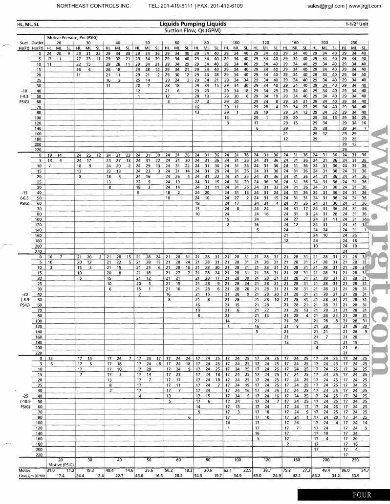
HL, Ml, SL liquids Pumping liquids 1-1/2" Unit
Suction Flow Qs (GPM), Motive Pressu re, Pm (PSIG)
Suet Outlet 20 30 40 50 60 80 100 120 160 200 250 I
Hillt) HqfFt) HL ML SL HL ML SL HL ML SL HL ML SL HL ML SL HL ML SL HL ML SL HL ML SL HL ML SL HL ML SL HL ML SL
0 24 20 9 29 31 22 29 34 30 29 34 36 29 34 40 29 34 40 29 34 40 29 34 40 29 34 40 29 34 40 29 34 40 5 17 11 27 23 11 29 32 21 29 34 29 29 34 40 29 34 40 29 34 40 29 34 40 29 34 40 29 34 40 29 34 40
10 11 22 15 29 26 11 29 34 21 29 34 29 29 34 40 29 34 40 29 34 40 29 34 40 29 34 40 29 34 40 15 16 6 26 18 29 28 12 29 34 21 29 34 40 29 34 40 29 34 40 29 34 40 29 34 40 29 34 40 20 11 21 11 29 21 2 29 30 12 29 23 28 29 34 40 29 34 40 29 34 40 29 34 40 29 34 40 25 16 3 25 14 29 24 3 29 34 21 29 34 34 29 34 40 29 34 40 29 34 40 29 34 40 30 11 20 7 28 18 29 34 15 29 34 30 29 34 40 29 34 40 29 34 40 29 34 40
-10 40 12 21 6 29 23 29 34 18 29 34 29 29 34 40 29 34 40 29 34 40 (-4.3 50 1 12 29 13 29 30 6 29 34 19 29 34 40 29 34 40 29 34 40 PSIG) 60 3 27 3 29 20 29 34 8 29 34 31 29 34 40 29 34 40
70 16 29 11 29 28 4 29 34 22 29 34 40 29 34 40 80 13 29 1 29 19 29 34 12 29 34 32 29 34 40
100 15 29 1 29 30 29 34 15 29 34 25 120 3 17 29 15 29 34 29 34 16 140 6 29 29 28 29 34 1 160 21 29 12 29 29 180 12 29 29 25 200 29 12 220 29
0 19 14 24 25 12 24 31 23 24 31 30 24 31 36 24 31 36 24 31 36 24 31 36 24 31 36 24 31 36 24 31 36 5 13 4 24 17 24 27 13 24 31 22 24 31 30 24 31 36 24 31 36 24 31 36 24 31 36 24 31 36 24 31 36
10 7 18 9 24 20 2 24 29 13 24 31 22 24 31 36 24 31 36 24 31 36 24 31 36 24 31 36 24 31 36 15 13 23 13 24 23 3 24 31 14 24 31 29 24 31 36 24 31 36 24 31 36 24 31 36 24 31 36 20 8 18 5 24 16 24 26 4 24 31 22 24 31 35 24 31 36 24 31 36 24 31 36 24 31 36 25 13 22 9 24 19 24 31 15 24 31 29 24 36 36 24 31 36 24 31 36 24 31 36 30 8 18 3 24 14 24 31 11 24 31 25 24 31 32 24 31 36 24 31 36 24 31 36
-15 40 9 18 2 24 20 24 31 13 24 31 24 24 31 36 24 31 36 24 31 36 (-6.5 50 10 24 10 24 27 2 24 31 15 24 31 31 24 31 36 24 31 36 PSIG) 60 18 24 17 24 31 4 24 31 26 24 31 36 24 31 36
70 15 24 8 24 24 24 31 17 24 31 36 24 31 36 80 10 24 24 16 24 31 8 24 31 28 24 31 36
100 15 24 24 27 24 31 11 24 31 24 120 2 16 24 12 24 31 24 31 12 140 5 24 24 24 24 31 1 160 21 24 10 24 25 180 12 24 24 16 200 10 24 10 220 24
0 16 7 21 20 3 21 28 15 21 28 24 21 28 31 21 28 31 21 28 31 21 28 31 21 28 31 21 28 31 21 28 31 5 10 20 12 21 22 5 21 28 15 21 28 24 21 28 31 21 28 31 21 28 31 21 28 31 21 28 31 21 28 31
10 3 15 3 21 15 21 25 6 21 28 16 21 28 30 21 28 31 21 28 31 21 28 31 21 28 31 21 28 31 15 10 20 8 21 18 21 27 7 21 28 24 21 28 31 21 28 31 21 28 31 21 28 31 21 28 31 20 5 15 21 12 21 21 21 28 17 21 28 30 21 28 31 21 28 31 21 28 31 21 28 31 25 10 20 5 21 15 21 28 9 21 28 24 21 28 31 21 28 31 21 28 31 21 28 31 30 6 15 1 21 10 21 28 6 21 28 20 21 28 31 21 28 31 21 28 31 21 28 31
-20 40 7 16 21 15 21 28 9 21 28 20 21 28 31 21 28 31 21 28 31 (-8.9 50 8 21 8 21 28 21 28 10 21 28 31 21 28 31 21 28 31 PSIG) 60 16 21 15 21 28 21 28 21 21 28 31 21 28 31
70 10 21 6 21 22 21 28 13 21 28 31 21 28 31 80 8 21 21 13 21 28 4 21 28 25 21 28 31
100 14 21 21 28 21 28 8 21 28 31 120 1 16 21 9 21 28 21 28 20 140 5 21 21 21 21 28 9 160 21 21 7 21 28 180 12 21 21 19 200 4 21 6 220 21
0 12 17 14 17 24 7 17 24 17 17 24 24 17 24 25 17 24 25 17 24 25 17 24 25 17 24 25 17 24 25 5 6 17 6 17 18 17 24 08 17 24 18 17 24 25 17 24 25 17 24 25 17 24 25 17 24 25 17 24 25
10 17 17 10 17 20 17 24 9 17 24 25 17 24 25 17 24 25 17 24. 25 17 24 25 17 24 25 15 7 17 3 17 14 17 23 17 24 18 17 24 25 17 24 25 17 24 25 17 24 25 17 24 25 20 13 17 7 17 17 17 24 18 17 24 25 17 24 25 17 24 25 17 24 25 17 24 25 25 8 17 17 11 17 24 2 17 24 19 17 24 25 17 24 25 17 24 25 17 24 25 30 2 17 17 7 17 24 17 24 16 17 24 25 17 24 25 17 24 25 17 24 25 ,
-25 40 4 13 17 15 17 24 5 17 24 16 17 24 25 17 24 25 17 24 25 (-10.9 50 5 17 6 17 24 17 24 7 17 24 25 17 24 25 17 24 25 I PSIG) 60 14 17 13 17 24 17 24 17 17 24 25 17 24 25
70 9 17 3 17 18 17 24 9 17 24 25 17 24 25 80 6 17 17 10 17 24 1 17 24 20 17 24 25
100 14 17 17 24 17 24 4 17 24 14 120 1 17 17 7 17 24 17 24 5 140 16 17 17 18 17 24 160 5 12 17 4 17 20 180 2 17 17 16 200 17 17 4 220 17
20 30 40 50 60 80 100 120 160 200 250 Motive (PSIG)
Motive 31.0 11.2 19.3 40.4 14.6 25.6 50.2 18.2 30.6 62.1 22.5 38.7 75.2 27.2 48.4 96.0 34.7 Flow,Qm (GPM) 17.4 34.4 12.4 22.7 45.6 16.5 28.2 54.5 19.7 34.9 69.0 24.9 42.2 86.2 31.2 53.9
FOUR
ww
w.jrgjt.com
NORTHEAST CONTROLS INC. TEL: 201-419-6111 | FAX: 201-419-6109 [email protected] | www.jrgjt.com
I SuctionDetermine
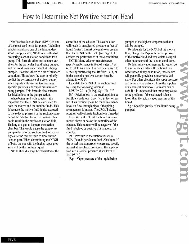
Net Positive Suction Head (NPSH) is one of the most used terms for pumps (including eductors) and also one of the least understood. Simply stated, NPSH is a method of evaluating a set of suction conditions for a pump. This formula takes into account variables for the particular liquid being pumped and the conditions under which it is being pumped. It corrects them to a set of standard conditions. This allows the user to reliably predict the performance of a given pump when liquids with varying temperatures, specific gravities, and vapor pressures are being pumped. This formula also corrects for friction loss in the pump suction.
When being used with eductors, it is important that the NPSH be calculated for both the motive and the suction fluids. This is because the motive fluid is also exposed to the reduced pressure in the suction chamber of the eductor. Failure to consider this could result in the motive or suction fluid flashing to a gas as it enters the suction chamber. This would cause the eductor to pump reduced or no suction fluid, or possibly cause the motive fluid to flow out the suction port. When determining the NPSH of both, the one with the higher vapor pressure will be the limiting liquid.
NPSH should always be calculated at the
centerline of the eductor. This calculation will result in an adjusted pressure in feet of liquid (water). It must be equal to or greater than the NPSH on the table (see page 1) to achieve the perfomlance at these conditions.
NOTE: Many eductor manufacturers specify performance in feet ofwater lift at 60 to 70°F. As a rule, this can be changed to NPSH by subtracting the lift from 33 Ft, or in the case of a positive suction head by adding it to 33 Ft.
Calculate the NPSH of the suction fluid by using the following formula:
NPSH =2.31 x (Ps-Pvp)/Sg +Hs - Hf Hf=Friction loss in the suction piping at
full flow conditions. Specified in feet of liquid. This frequently can be found in a handbook on flow through pipes if the piping arrangement is known. The JRG/JT sizing program will estimate friction loss ifneeded.
Hs = Vertical feet that the liquid is being moved above or below the centerline of the eductor. This number will be negative if the fluid is below, or positive if it is above, the eductor.
Ps = Pressure in the suction vessel in PSIA (Pounds per Square Inch Absolute). If the vessel is at atmospheric pressure, specify normal atmospheric pressure at the application site. (Normal pressure at sea level is 14.7 PSIA.)
Pvp = Vapor pressure of the liquid being
pumped at the highest temperature that it will be pumped.
To calculate for the NPSH of the motive fluid, change the Pvp to the vapor pressure of the motive fluid and recalculate using all other parameters of the suction conditions.
To determine vapor pressure for water, go to a set of steam tables. If the liquid is a water-based slurry or solution, these tables will generally provide a conservative estimate. For other chemicals the vapor pressure can generally be obtained from the supplier or a chemical handbook. Estimates can be used if it is understood that these may cause some problems if the estimated value is lower than the actual vapor pressure of the liquid.
Sg = Specific gravity of the liquid being pumped.
FIVE
ww
w.jrgjt.com
NORTHEAST CONTROLS INC. TEL: 201-419-6111 | FAX: 201-419-6109 [email protected] | www.jrgjt.com
I Liquid Eductors for Liquids
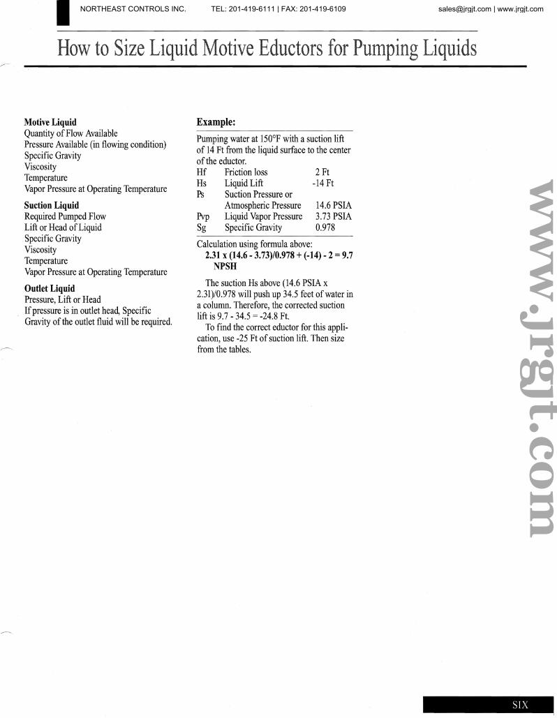
Motive Liquid Quantity of Flow Available Pressure Available (in flowing condition) Specific Gravity Viscosity Temperature Vapor Pressure at Operating Temperature
Suction Liquid Required Pumped Flow Lift or Head ofLiquid Specific Gravity Viscosity Temperature Vapor Pressure at Operating Temperature
Outlet Liquid Pressure, Lift or Head Ifpressure is in outlet head, Specific Gravity of the outlet fluid will be required.
Example:
Pumping water at 150°F with a suction lift of 14 Ft from the liquid surface to the center of the eductor. Hf Friction loss 2Ft Hs Liquid Lift -14 Ft Ps Suction Pressure or
Atmospheric Pressure 14.6 PSIA Pvp Liquid Vapor Pressure 3.73 PSIA Sg Specific Gravity 0.978
Calculation using formula above: 2.31 x (14.6 - 3.73)/0.978 + (-14) - 2 = 9.7
NPSH
The suction Hs above (14.6 PSIA x 2.31)/0.978 will push up 34.5 feet ofwater in a column. Therefore, the corrected suction lift is 9.7 - 34.5 = -24.8 Ft.
To find the correct eductor for this application, use -25 Ft of suction lift. Then size from the tables.
ww
w.jrgjt.com
NORTHEAST CONTROLS INC. TEL: 201-419-6111 | FAX: 201-419-6109 [email protected] | www.jrgjt.com
I
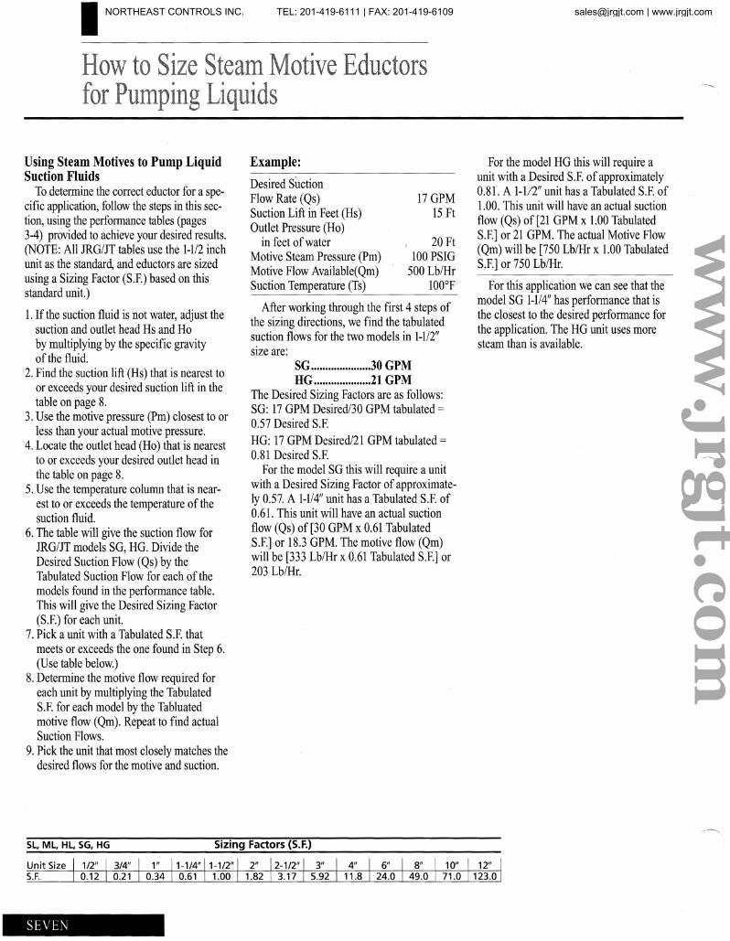
Using Steam Motives to Pump Liquid Suction Fluids . ~o dete:mi?e the correct eductor for a spe
cIfIC apphcatlOn, follow the steps in this section, using the performance tables (pages 3-4) provided to achieve your desired results. (NOTE: All JRG/JT tables use the 1-112 inch unit as the standard, and eductors are sized using a Sizing Factor (S.F.) based on this standard unit.)
1. If th~ suction fluid is not water, adjust the suctIon and outlet head Rs and Ho by multiplying by the specific gravity of the fluid.
2. Find the suction lift (Rs) that is nearest to or exceeds your desired suction lift in the table on page 8.
3. Use the motive pressure (Pm) closest to or less than your actual motive pressure.
4. Locate the outlet head (Ho) that is nearest to or exceeds your desired outlet head in the table on page 8.
5. Use the temperature column that is nearest to or exceeds the temperature of the suction fluid.
6. The table will give the suction flow for JRG/JT models SG, HG. Divide the Desired Suction Flow (Qs) by the Tabulated Suction Flow for each of the models found in the performance table. This will give the Desired Sizing Factor (S.F.) for each unit.
7. Pick a unit with a Tabulated S.F. that meets or exceeds the one found in Step 6. (Use table below.)
8. Determine the motive flow required for each unit by multiplying the Tabulated S.F. for each model by the Tabluated motive flow (Qm). Repeat to find actual Suction Flows.
9. Pic~ the unit that most closely matches the deSIred flows for the motive and suction.
Unit Size S.F.
SEVEN
Example:
Desired Suction Flow Rate (Qs) 17 GPM Suction Lift in Feet (Hs) 15 Ft Outlet Pressure (Ho)
in feet of water 20 Ft Motive Steam Pressure (Pm) 100 PSIG Motive Flow Available(Qm) 500 LblHr Suction Temperature (Ts) lOO°F
A~e.r workin~ through the first 4 steps of the slZlng dlrectlOns, we find the tabulated s~ction flows for the two models in 1-112" SIze are:
SG .....................30 GPM HG ....................21 GPM
The Desired Sizing Factors are as follows: SG: 17 GPM Desired/30 GPM tabulated =
0.57 Desired S.F. HG: 17 GPM Desired/2l GPM tabulated = 0.81 Desired S.F.
.For the model SG this will require a unit WIth a Desired Sizing Factor of approximately 0.57. A 1-114" unit has a Tabulated S.F. of 0.61. This unit will have an actual suction flow (Qs) of [30 GPM x 0.61 Tabulated S.F.] or 18.3 GPM. The motive flow (Qm) will be [333 LblHr x 0.61 Tabulated S.F.] or 203 LblHr.
~or !he model HG this will require a umt WIth a Desired S.F. of approximately 0.81. A 1-1/2" unit has a Tabulated S.F. of 1.00. This unit will have an actual suction flow (Qs) of [21 GPM x 1.00 Tabulated S.F.] or 21 GPM. The actual Motive Flow (Qm) will be [750 Lb/Hr x 1.00 Tabulated S.F.] or 750 Lb/Hr.
For this application we can see that the model SG 1-1/4" has performance that is the closest to the desired performance for the application. The HG unit uses more stean1 than is available.
ww
w.jrgjt.com
NORTHEAST CONTROLS INC. TEL: 201-419-6111 | FAX: 201-419-6109 [email protected] | www.jrgjt.com
10
20
30
40
50
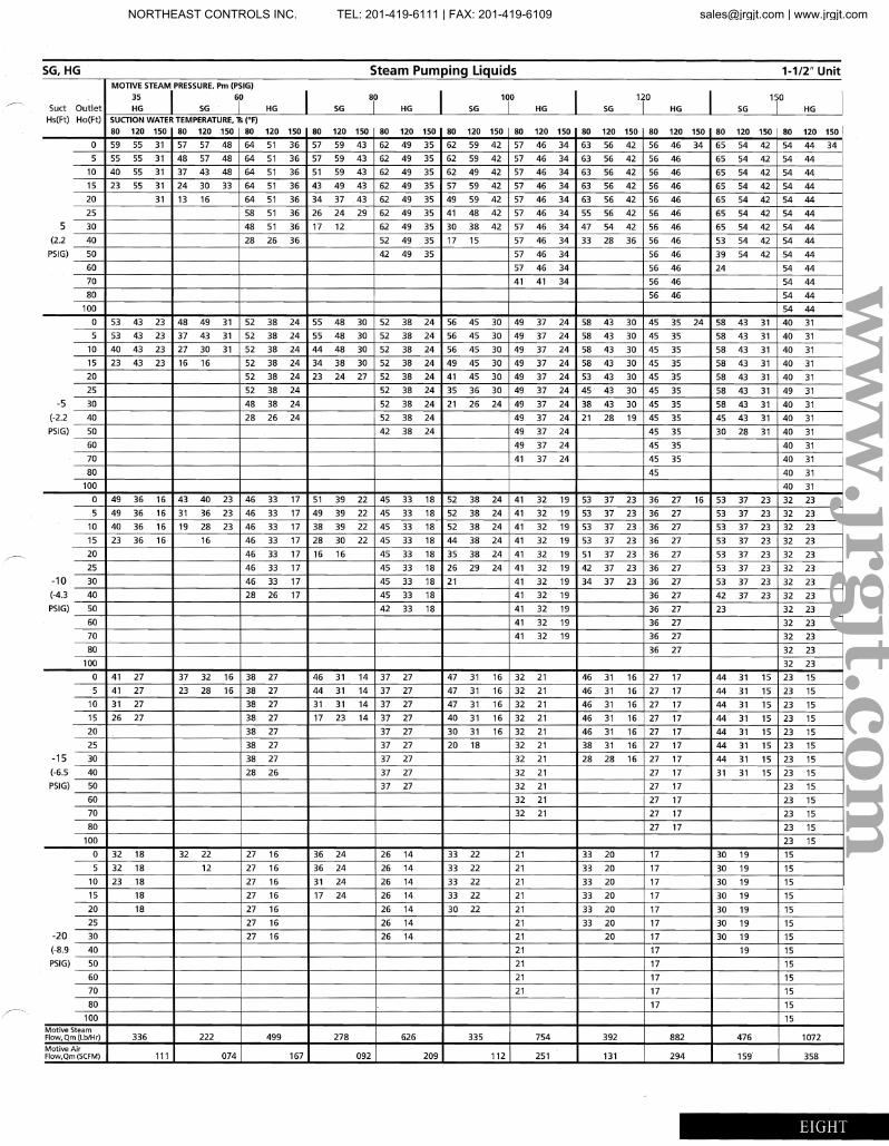
SG,HG Steam Pumping Liquids 1-1/2" Unit
Suet Outlet
MOTIVE STEAIIJI(RESSURE, Pm (PSIG)
3S 1 HG SG HG I SG
8 1 0
HG I SG 100
HG I SG T HG I SG 110
HG I Hs(Ft) Ha(Ft) SUCTION WATER TEMPERATURE, Ts (OF)
80 120 150 80 120 .150 80 120 150 80 120 150 80 120 150 80 120 150 80 120 150 80 120 150 80 120 150 80 120 150 80 120 150 I a 59 55 31 57 57 48 64 51 36 57 59 43 62 49 35 62 59 42 57 46 34 63 56 42 56 46 34 65 54 42 54 44 34
5 55 55 31 48 57 48 64 51 36 57 59 43 62 49 35 62 59 42 57 46 34 63 56 42 56 46 65 54 42 54 44
40 55 31 37 43 48 64 51 36 51 59 43 62 49 35 62 49 42 57 46 34 63 56 42 56 46 65 54 42 54 44
15 23 55 31 24 30 33 64 51 36 43 49 43 62 49 35 57 59 42 57 46 34 63 56 42 56 46 65 54 42 54 44 20 31 13 16 64 51 36 34 37 43 62 49 35 49 59 42 57 46 34 63 56 42 56 46 65 54 42 54 44
25 58 51 36 26 24 29 62 49 35 41 48 42 57 46 34 55 56 42 56 46 65 54 42 54 44
5 30 48 51 36 17 12 62 49 35 30 38 42 57 46 34 47 54 42 56 46 65 54 42 54 44 (2.2 40 28 26 36 52 49 35 17 15 57 46 34 33 28 36 56 46 53 54 42 54 44
PSIG) 50 42 49 35 57 46 34 56 46 39 54 42 54 44
60 57 46 34 56 46 24 54 44
70 41 41 34 56 46 54 44
80 56 46 54 44
100 54 44
0 53 43 23 48 49 31 52 38 24 55 48 30 52 38 24 56 45 30 49 37 24 58 43 30 45 35 24 58 43 31 40 31
5 53 43 23 37 43 31 52 38 24 55 48 30 52 38 24 56 45 30 49 37 24 58 43 30 45 35 58 43 31 40 31
10 40 43 23 27 30 31 52 38 24 44 48 30 52 38 24 56 45 30 49 37 24 58 43 30 45 35 58 43 31 40 31
15 23 43 23 16 16 52 38 24 34 38 30 52 38 24 49 45 30 49 37 24 58 43 30 45 35 58 43 31 40 31
52 38 24 23 24 27 52 38 24 41 45 30 49 37 24 53 43 30 45 35 58 43 31 40 31
25 52 38 24 52 38 24 35 36 30 49 37 24 45 43 30 45 35 58 43 31 49 31 -5 30 48 38 24 52 38 24 21 26 24 49 37 24 38 43 30 45 35 58 43 31 40 31
(-2.2 40 28 26 24 52 38 24 49 37 24 21 28 19 45 35 45 43 31 40 31
PSIG) 50 42 38 24 49 37 24 45 35 30 28 31 40 31
60 49 37 24 45 35 40 31
70 41 37 24 45 35 40 31
80 45 40 31
100 40 31
0 49 36 16 43 40 23 46 33 17 51 39 22 45 33 18 52 38 24 41 32 19 53 37 23 36 27 16 53 37 23 32 23
5 49 36 16 31 36 23 46 33 17 49 39 22 45 33 18 52 38 24 41 32 19 53 37 23 36 27 53 37 23 32 23 10 40 36 16 19 28 23 46 33 17 38 39 22 45 33 18 52 38 24 41 32 19 53 37 23 36 27 53 37 23 32 23
15 23 36 16 16 46 33 17 28 30 22 45 33 18 44 38 24 41 32 19 53 37 23 36 27 53 37 23 32 23
20 46 33 17 16 16 45 33 18 35 38 24 41 32 19 51 37 23 36 27 53 37 23 32 23
25 46 33 17 45 33 18 26 29 24 41 32 19 42 37 23 36 27 53 37 23 32 23
-10 46 33 17 45 33 18 21 41 32 19 34 37 23 36 27 53 37 23 32 23
(-4.3 40 28 26 17 45 33 18 41 32 19 36 27 42 37 23 32 23
PSIG) 50 42 33 18 41 32 19 36 27 23 32 23
60 41 32 19 36 27 32 23
70 41 32 19 36 27 32 23
80 36 27 32 23
100 32 23
0 41 27 37 32 16 38 27 46 31 14 37 27 47 31 16 32 21 46 31 16 27 17 44 31 15 23 15
5 41 27 23 28 16 38 27 44 31 14 37 27 47 31 16 32 21 46 31 16 27 17 44 31 15 23 15
10 31 27 38 27 31 31 14 37 27 47 31 16 32 21 46 31 16 27 17 44 31 15 23 15
15 26 27 38 27 17 23 14 37 27 40 31 16 32 21 46 31 16 27 17 44 31 15 23 15
20 38 27 37 27 30 31 16 32 21 46 31 16 27 17 44 31 15 23 15
25 38 27 37 27 20 18 32 21 38 31 16 27 17 44 31 15 23 15 -15 30 38 27 37 27 32 21 28 28 16 27 17 44 31 15 23 15
(-6.5 28 26 37 27 32 21 27 17 31 31 15 23 15 P5IG) 50 37 27 32 21 27 17 23 15
60 32 21 27 17 23 15
70 32 21 27 17 23 15
80 27 17 23 15
100 23 15
0 32 18 32 22 27 16 36 24 26 14 33 22 21 33 20 17 30 19 15
5 32 18 12 27 16 36 24 26 14 33 22 21 33 20 17 30 19 15
10 23 18 27 16 31 24 26 14 33 22 21 33 20 17 30 19 15
15 18 27 16 17 24 26 14 33 22 21 33 20 17 30 19 15 I 20 18 27 16 26 14 30 22 21 33 20 17 30 19 15
25 27 16 26 14 21 33 20 17 30 19 15
-20 30 27 16 26 14 21 20 17 30 19 15 (-8,9 40 21 17 19 15
PSIG) 21 17 15
60 21 17 15
70 21 17 15
80 17 15
100 15 Motive Steam Flow, Om (Lb/Hr) 336 222 499 278 626 335 754 392 882 476 1072 Motive Air Flow,Om (SCFM) 111 074 167 092 209 112 251 131 294 159 358
EIGHT
ww
w.jrgjt.com
NORTHEAST CONTROLS INC. TEL: 201-419-6111 | FAX: 201-419-6109 [email protected] | www.jrgjt.com
I
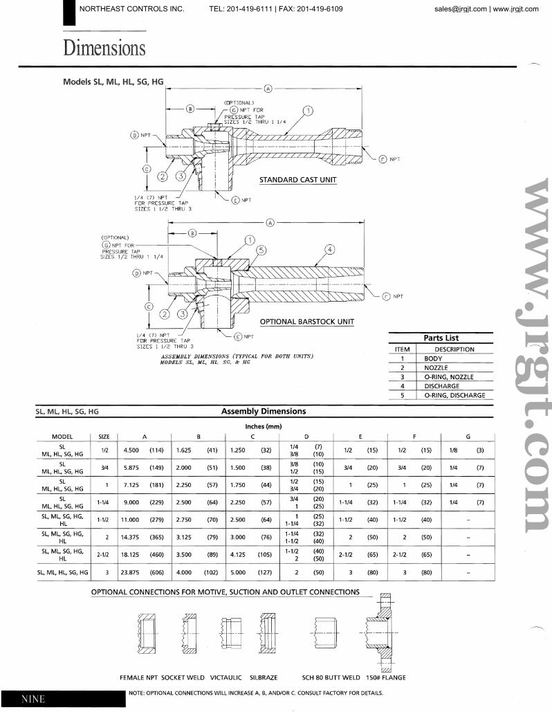
Models Sl, Ml, HL, SG, HG 1-----------0---------1
1/4 0) NPT FOR PRESSURE TAP SIZES 1 112 THRU 3
(OPTIONAl)
(B) ------ikJ © NPT FORI PRESSURE TAP
. . SIZES 112 THRU 1 l/4
@NPT
CD NPT
STANDARD CAST UNIT
1/4 0) NPT FOR PRESSURE TAP SIZES 1 1/2 THRU 3
-----------0-------------~F------+---~l ~
1 1/4 I ~_~_-~'~'~I:~~~~,,~,,~,,~~~~~~ @NPT
CD NPT
OPTIONAL BARSTOCK UNIT
(i)NPT Parts List ITEM DESCRIPTION
ASSEMBLY DIMENSIONS (TYPICAL FOR BOTH UNITS) BODYMODELS SL, ML, HL SG. &- He
2 NOZZLE
3 O-RING, NOZZLE
4 DISCHARGE
5 O-RING, DISCHARGE
SL, ML, HL, SG, HG Assembly Dimensions
Inches (mm)
MODEL SIZE A B C D E F G
SL 1/4 (7)1/2 4.500 (114) 1.625 (41) 1.250 (32) 1/2 (15) 1/2 (15) 1/8 (3)
ML, HL, SG, HG 3/8 (10)
SL 3/8 (10)3/4 5.875 (149) 2.000 (51) 1.500 (38) 3/4 (20) 3/4 (20) 1/4 (7)
ML, HL, SG, HG 1/2 (15)
SL 1/2 (15)1 7.125 (181) 2.250 (57) 1.750 (44) 1 (25) 1 (25) 1/4 (7)
ML, HL, SG, HG 3/4 (20)
SL 3/4 (20)1-1/4 9.000 (229) 2.500 (64) 2.250 (57) 1-114 (32) 1-114 (32) 1/4 (7)
ML, HL, SG, HG 1 (25)
SL, ML, SG, HG, 1 (25)1·1/2 11.000 (279) 2.750 (70) 2.500 (64) 1-112 (40) 1-1/2 (40)
HL 1-1/4 (32)
SL, ML, SG, HG, 1-1/4 (32)2 14.375 (365) 3.125 (79) 3.000 (76) 2 (50) 2 (50)
HL 1-1/2 (40)
SL, ML, SG, HG, 1-1/2 (40)2·1/2 18.125 (460) 3.500 (89) 4.125 (105) 2-1/2 (65) 2-1/2 (65)
HL 2 (50)
SL, ML, HL, SG, HG 3 23.875 (606) 4.000 (102) 5.000 (127) 2 (50) 3 (80) 3 (80)
OPTIONAL CONNECTIONS FOR MOTIVE, SUCTION AND OUTLET CONNECTIONS
uLID UITn " FEMALE NPT SOCKET WELD VICTAULIC SILBRAZE SCH 80 Bun WELD 150# FLANGE
NOTE: OPTIONAL CONNECTIONS WILL INCREASE A, B, AND/OR C. CONSULT FACTORY FOR DETAILS.
NINE
ww
w.jrgjt.com
NORTHEAST CONTROLS INC. TEL: 201-419-6111 | FAX: 201-419-6109 [email protected] | www.jrgjt.com