jerrold avenue bridge-north span …disneyconstruction.com/projects/023 - san francisco...jerrold...
TRANSCRIPT
JERROLD AVENUE BRIDGE-NORTH SPAN
REMOVAL PROJECT PHASE 1
Contract No. 05-PCJPB-P-029
PENINSULA CORRIDOR JOINT POWERS BOARD
SUPPLEMENTAL TECHNICAL PROVISIONS
CONFORMED

05-PCJPB-C-029
CONFORMED
TABLE OF CONTENTS
SUPPLEMENTAL TECHNICAL PROVISIONS Section Number
Title
DIVISION 2 – SITE CONSTRUCTION
02110 02200 02300 02455 02810
Site Clearing Support of Excavation Earthwork Tieback Anchors Chain Link Fence
DIVISION 3 - CONCRETE 03100 03150 03170 03200 03300
Concrete Forming Concrete Accessories Concrete Finishing Concrete Reinforcing Cast-In-Place Concrete
DIVISION 5 – METALS
05200 Structural Steel
05-PCJPB-C-029
CONFORMED SECTION 02110-1 SITE CLEARING
SECTION 02110
SITE CLEARING
Caltrain Standard Specification Section 02110, Site Clearing, is invoked for this contract.
END OF SECTION
05-PCJPB-C-029
CONFORMED SECTION 02200-1 SUPPORT OF EXCAVATION
SECTION 02200
SUPPORT OF EXCAVATION
Caltrain Standard Specification Section 02200, Support of Excavation, is invoked for this contract.
END OF SECTION
05-PCJPB-C-029
CONFORMED SECTION 02300-1 EARTHWORK
SECTION 02300
EARTHWORK
Caltrain Standard Specification Section 02300, Earthwork, is invoked for this contract.
END OF SECTION
05-PCJPB-C-029
CONFORMED SECTION 02455-1 TIEBACK ANCHORS
SECTION 02455
TIEBACK ANCHORS
Part 1 – GENERAL
1.01 DESCRIPTION
A. This section specifies requirements for designing, furnishing and installing tieback anchors for structures in conformance with the details shown on the plans and as specified in these specifications and special provisions. A tieback anchor consists of a steel bar with an anchorage assembly placed in a cored, formed, or drilled hole, and then grouted and, possibly, post-grouted. The work includes furnishing all engineering and design services, supervision, labor, materials, and equipment to perform all work necessary to install and test the tieback anchors per the specifications described herein and as shown on the drawings.
1.02 REFERENCE STANDARDS
A. PCJPB Engineering Standards for Excavation Support Systems, 2003
B. ASTM International (ASTM):
1. A123 Specification for Zinc (Hot-Dip Galvanized) Coatings on Iron and Steel Products
2. A153 Specification for Zinc Coating (Hot-Dip) on Iron and Steel Hardware
3. A252 Specification for Welded and Seamless Steel Pipe Piles
4. A572 Specification for High-Strength Low-Alloy Columbium-Vanadium Structural Steel
5. A615 Specification for Deformed and Plain Carbon-Steel Bars for Concrete Reinforcement
6. A722 Specification for Uncoated High-Strength Steel Bars for Prestressing Concrete
7. A775 Specification for Epoxy-Coated Steel Reinforcing Bars
8. D792 Standard Test Methods for Density and Specific Gravity (Relative Density) of Plastics by Displacement
9. D1784 Specification for Rigid Poly(Vinyl Chloride) (PVC) Compounds and Chlorinated Poly(Vinyl Chloride) (CPVC) Compounds
10. D3689 Standard Test Methods for Deep Foundations Under Static Axial Tensile Load
C. State of California, Department of Transportation Standard Specifications (Caltrans):
1. Section 50, Prestressing Concrete
2. Section 90, Portland Cement Concrete
05-PCJPB-C-029
CONFORMED SECTION 02455-2 TIEBACK ANCHORS
D. Post-Tensioning Institute:
1. Recommendations for Prestressed Rock and Soil Anchors, 2004
2. Specification for Unbonded Single Strand Tendons, 2000
1.03 QUALITY CONTROL
A. Tieback Anchor installation and testing quality control shall follow procedures specified in Section 01400 –Quality Control.
B. The tieback anchor contractor shall be fully experienced in all aspects of tieback anchor design and construction, and shall furnish all necessary equipment, materials, skilled labor, and supervision to carry out the contract. The Contractor will have successfully completed at least five projects in the previous five years of similar scope and size. Provide project name, sample drawings and Owner contact information for each project. Provide resumes of key personnel who will be present on site (and will be material involved) and who will each have at least three years of relevant experience. These personnel shall include superintendent, driller, and project engineer/manager.
C. Submit a separate quality control plan for installation of the tieback anchors. The submitted plan shall include procedures for material control, installation and testing, as a minimum. Include samples of all forms to be used for installation and testing records.
1.04 SUBMITTALS
A. Prior to installation of Tieback Anchors, submit shop drawings and design calculations to the Engineer for approval. Submittal shall be sealed and signed by a professional engineer currently registered in the State of California. Submitted package, as a minimum, shall include the following:
1. The proposed schedule and detailed construction sequence of the installation and grouting of tieback anchors. The construction sequence shall include a step-by-step procedure describing all aspects of the anchor installation in sufficient detail so that the Engineer can monitor the construction and quality of the anchors.
2. Complete details and specifications for the anchorage system and tieback anchors, including grouting methods.
3. Drilling methods and equipment, including proposed drilled hole diameter and equipment space requirements.
4. Repair procedure for damaged sheathing.
5. Grout mix designs and testing procedures.
6. Grout placement procedures and equipment, including minimum required cure time.
7. Proposed tieback anchor testing equipment, including jacking frame and appurtenant bracing, and the method and equipment for determining anchor displacement during testing.
8. Details for providing bonded and unbonded lengths, including type of packers or other appropriate devices, if used.

05-PCJPB-C-029
CONFORMED SECTION 02455-3 TIEBACK ANCHORS
9. Design calculation performed by or under the responsible charge of the professional engineer signing the submitted package.
10. Working and shop drawings that include anchor location and pattern, anchor design loads, type and size of reinforcing steel, minimum total bond length, angle from horizontal, total anchor length, grouting volumes and maximum pressures, anchorage details, post-grouting details, and corrosion protection system.
11. Plan describing how surface water, drill flush, and excess water will be controlled and disposed of.
B. The Contractor shall submit certified mill test reports, properly marked, for the reinforcing steel, as the materials are delivered. The ultimate strength, yield strength, elongation and composition shall be included. For steel pipe used as permanent casing, the Contractor shall submit a minimum of two representative coupon test or mill certifications (if available) on each load delivered to the project.
C. Test Frame Design: The Contractor shall submit design calculations and detail drawings for a tieback anchor test frame. The load test frame shall be designed to carry at least twice the maximum test load. Calculations and drawings shall be sealed and signed by a professional engineer currently registered in the State of California.
D. Installation Records: As a minimum, the following records shall be completed and submitted by the Contractor within 24 hours after each anchor installation is completed:
1. Anchor drilling duration and observations (e.g., flush return)
2. Information on soil and rock encountered, including description of strata, water, etc.
3. Approximate final tip elevation
4. Cut-off elevation
5. Angle from horizontal for each anchor
6. Design loads
7. Description of unusual installation behavior, conditions
8. Any deviations from the intended parameters
9. Grout pressures attained, where applicable
10. Grout quantities pumped
11. Anchor materials and dimensions
E. At the completion of testing tieback anchors, or when requested by the Engineer, the Contractor shall furnish to the Engineer complete test results for each ground anchor tested. Submit the following data for each ground anchor test.
1. Key personnel
05-PCJPB-C-029
CONFORMED SECTION 02455-4 TIEBACK ANCHORS
2. Test loading equipment including calibration reports (jacks, pressure gauges, load cell, displacement gauges, etc.).
3. Tieback Anchor location
4. Time and date of:
4.1. Drilling
4.2. Installation
4.3. Grouting
4.4. Testing
5. Hole diameter and depth
6. Drilling method
7. Soil or rock classification and description
8. Bonded and unbonded length
9. Quantity of ground water encountered within the bonded length
10. Grout quantity and pressure used within the bonded length
11. Anchor end movement at each load increment or at each time increment during the load hold period
12. Discussion of any deviation from specified procedure or unexpected results
1.05 ALLOWABLE TOLERANCES
A. The centerline of the tieback anchor shall not be more than 3 inches from indicated plan and elevation location.
B. Anchor alignment shall be within 2% of design alignment.
1.06 DESIGN CRITERIA
A. The tieback anchors shall be designed to meet the specified loading and movement conditions shown on the drawings. The calculations and drawings required from the Contractor shall be submitted to the Engineer for review and acceptance in accordance with Section 1.04. Tieback anchors shall be designed in accordance with the Post-Tensioning Institute, Recommendations for Prestressed Rock and Soil Anchors.
B. The structural capacity shall be determined as:
For Compression: Pc = 0.60 * (0.85 * fc * Agrout + fycasing * Acasing + fybar * Abar)
For Tension:
Pt = 0.60 * (fycasing * Acasing + fybar * Abar)
05-PCJPB-C-029
CONFORMED SECTION 02455-5 TIEBACK ANCHORS
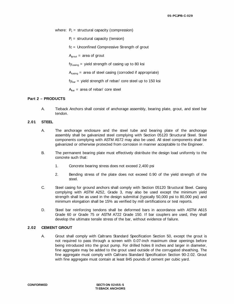
where: Pc = structural capacity (compression)
Pt = structural capacity (tension)
fc = Unconfined Compressive Strength of grout
Agrout = area of grout
fycasing = yield strength of casing up to 80 ksi
Acasing = area of steel casing (corroded if appropriate)
fybar = yield strength of rebar/ core steel up to 150 ksi
Abar = area of rebar/ core steel
Part 2 – PRODUCTS
A. Tieback Anchors shall consist of anchorage assembly, bearing plate, grout, and steel bar tendon.
2.01 STEEL
A. The anchorage enclosure and the steel tube and bearing plate of the anchorage assembly shall be galvanized steel complying with Section 05120 Structural Steel. Steel components complying with ASTM A572 may also be used. All steel components shall be galvanized or otherwise protected from corrosion in manner acceptable to the Engineer.
B. The permanent bearing plate must effectively distribute the design load uniformly to the concrete such that:
1. Concrete bearing stress does not exceed 2,400 psi
2. Bending stress of the plate does not exceed 0.90 of the yield strength of the steel.
C. Steel casing for ground anchors shall comply with Section 05120 Structural Steel. Casing complying with ASTM A252, Grade 3, may also be used except the minimum yield strength shall be as used in the design submittal (typically 50,000 psi to 80,000 psi) and minimum elongation shall be 15% as verified by mill certifications or test reports.
D. Steel bar reinforcing tendons shall be deformed bars in accordance with ASTM A615 Grade 60 or Grade 75 or ASTM A722 Grade 150. If bar couplers are used, they shall develop the ultimate tensile stress of the bar, without evidence of failure.
2.02 CEMENT GROUT
A. Grout shall comply with Caltrans Standard Specification Section 50, except the grout is not required to pass through a screen with 0.07-inch maximum clear openings before being introduced into the grout pump. For drilled holes 8 inches and larger in diameter, fine aggregate may be added to the grout used outside of the corrugated sheathing. The fine aggregate must comply with Caltrans Standard Specification Section 90-2.02. Grout with fine aggregate must contain at least 845 pounds of cement per cubic yard.
05-PCJPB-C-029
CONFORMED SECTION 02455-6 TIEBACK ANCHORS
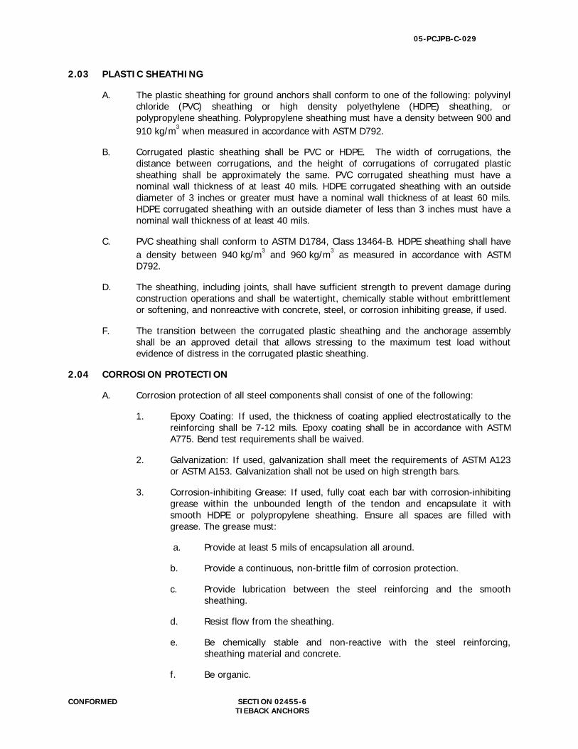
2.03 PLASTIC SHEATHING
A. The plastic sheathing for ground anchors shall conform to one of the following: polyvinyl chloride (PVC) sheathing or high density polyethylene (HDPE) sheathing, or polypropylene sheathing. Polypropylene sheathing must have a density between 900 and 910 kg/m3 when measured in accordance with ASTM D792.
B. Corrugated plastic sheathing shall be PVC or HDPE. The width of corrugations, the distance between corrugations, and the height of corrugations of corrugated plastic sheathing shall be approximately the same. PVC corrugated sheathing must have a nominal wall thickness of at least 40 mils. HDPE corrugated sheathing with an outside diameter of 3 inches or greater must have a nominal wall thickness of at least 60 mils. HDPE corrugated sheathing with an outside diameter of less than 3 inches must have a nominal wall thickness of at least 40 mils.
C. PVC sheathing shall conform to ASTM D1784, Class 13464-B. HDPE sheathing shall have a density between 940 kg/m3 and 960 kg/m3 as measured in accordance with ASTM D792.
D. The sheathing, including joints, shall have sufficient strength to prevent damage during construction operations and shall be watertight, chemically stable without embrittlement or softening, and nonreactive with concrete, steel, or corrosion inhibiting grease, if used.
F. The transition between the corrugated plastic sheathing and the anchorage assembly shall be an approved detail that allows stressing to the maximum test load without evidence of distress in the corrugated plastic sheathing.
2.04 CORROSION PROTECTION
A. Corrosion protection of all steel components shall consist of one of the following:
1. Epoxy Coating: If used, the thickness of coating applied electrostatically to the reinforcing shall be 7-12 mils. Epoxy coating shall be in accordance with ASTM A775. Bend test requirements shall be waived.
2. Galvanization: If used, galvanization shall meet the requirements of ASTM A123 or ASTM A153. Galvanization shall not be used on high strength bars.
3. Corrosion-inhibiting Grease: If used, fully coat each bar with corrosion-inhibiting grease within the unbounded length of the tendon and encapsulate it with smooth HDPE or polypropylene sheathing. Ensure all spaces are filled with grease. The grease must:
a. Provide at least 5 mils of encapsulation all around.
b. Provide a continuous, non-brittle film of corrosion protection.
c. Provide lubrication between the steel reinforcing and the smooth sheathing.
d. Resist flow from the sheathing.
e. Be chemically stable and non-reactive with the steel reinforcing, sheathing material and concrete.
f. Be organic.
05-PCJPB-C-029
CONFORMED SECTION 02455-7 TIEBACK ANCHORS
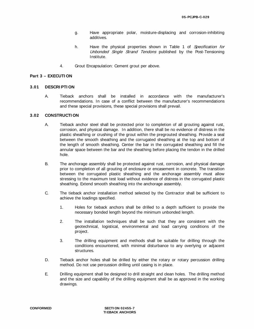
g. Have appropriate polar, moisture-displacing and corrosion-inhibiting additives.
h. Have the physical properties shown in Table 1 of Specification for Unbonded Single Strand Tendons published by the Post-Tensioning Institute.
4. Grout Encapsulation: Cement grout per above.
Part 3 – EXECUTION 3.01 DESCRIPTION
A. Tieback anchors shall be installed in accordance with the manufacturer's recommendations. In case of a conflict between the manufacturer's recommendations and these special provisions, these special provisions shall prevail.
3.02 CONSTRUCTION
A. Tieback anchor steel shall be protected prior to completion of all grouting against rust, corrosion, and physical damage. In addition, there shall be no evidence of distress in the plastic sheathing or crushing of the grout within the pregrouted sheathing. Provide a seal between the smooth sheathing and the corrugated sheathing at the top and bottom of the length of smooth sheathing. Center the bar in the corrugated sheathing and fill the annular space between the bar and the sheathing before placing the tendon in the drilled hole.
B. The anchorage assembly shall be protected against rust, corrosion, and physical damage prior to completion of all grouting of enclosure or encasement in concrete. The transition between the corrugated plastic sheathing and the anchorage assembly must allow stressing to the maximum test load without evidence of distress in the corrugated plastic sheathing. Extend smooth sheathing into the anchorage assembly.
C. The tieback anchor installation method selected by the Contractor shall be sufficient to achieve the loadings specified.
1. Holes for tieback anchors shall be drilled to a depth sufficient to provide the necessary bonded length beyond the minimum unbonded length.
2. The installation techniques shall be such that they are consistent with the geotechnical, logistical, environmental and load carrying conditions of the project.
3. The drilling equipment and methods shall be suitable for drilling through the conditions encountered, with minimal disturbance to any overlying or adjacent structures.
D. Tieback anchor holes shall be drilled by either the rotary or rotary percussion drilling method. Do not use percussion drilling until casing is in place.
E. Drilling equipment shall be designed to drill straight and clean holes. The drilling method and the size and capability of the drilling equipment shall be as approved in the working drawings.
05-PCJPB-C-029
CONFORMED SECTION 02455-8 TIEBACK ANCHORS
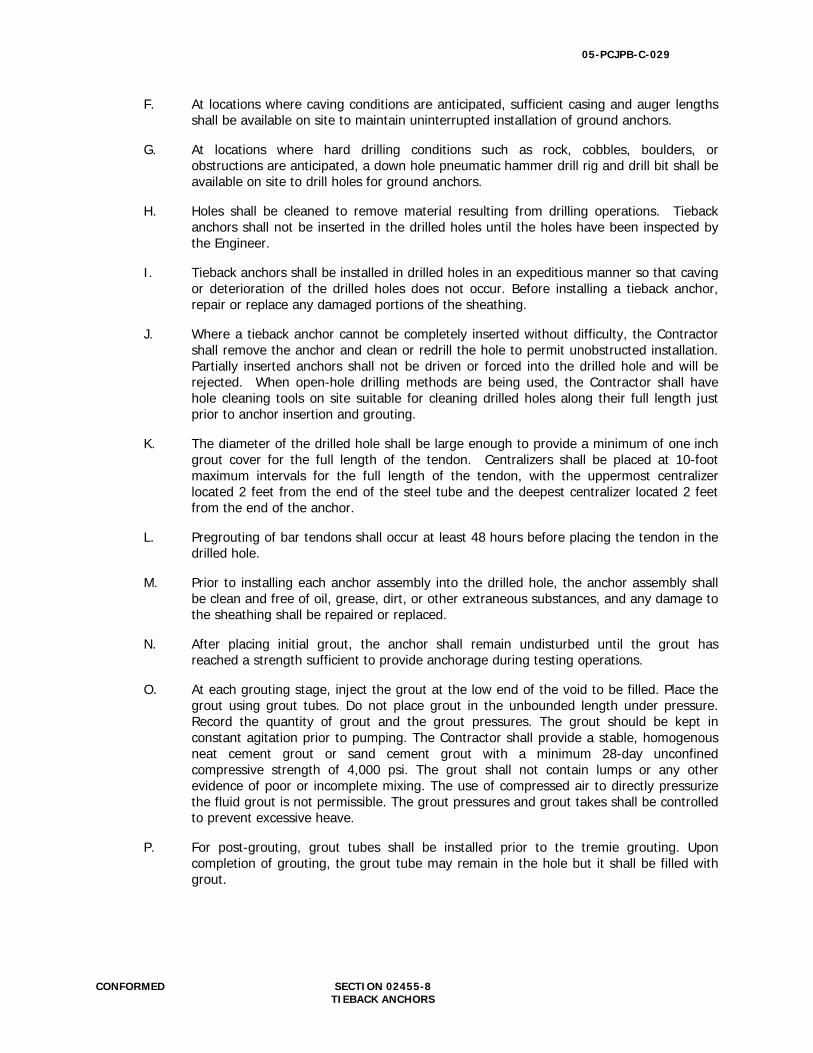
F. At locations where caving conditions are anticipated, sufficient casing and auger lengths shall be available on site to maintain uninterrupted installation of ground anchors.
G. At locations where hard drilling conditions such as rock, cobbles, boulders, or obstructions are anticipated, a down hole pneumatic hammer drill rig and drill bit shall be available on site to drill holes for ground anchors.
H. Holes shall be cleaned to remove material resulting from drilling operations. Tieback anchors shall not be inserted in the drilled holes until the holes have been inspected by the Engineer.
I. Tieback anchors shall be installed in drilled holes in an expeditious manner so that caving or deterioration of the drilled holes does not occur. Before installing a tieback anchor, repair or replace any damaged portions of the sheathing.
J. Where a tieback anchor cannot be completely inserted without difficulty, the Contractor shall remove the anchor and clean or redrill the hole to permit unobstructed installation. Partially inserted anchors shall not be driven or forced into the drilled hole and will be rejected. When open-hole drilling methods are being used, the Contractor shall have hole cleaning tools on site suitable for cleaning drilled holes along their full length just prior to anchor insertion and grouting.
K. The diameter of the drilled hole shall be large enough to provide a minimum of one inch grout cover for the full length of the tendon. Centralizers shall be placed at 10-foot maximum intervals for the full length of the tendon, with the uppermost centralizer located 2 feet from the end of the steel tube and the deepest centralizer located 2 feet from the end of the anchor.
L. Pregrouting of bar tendons shall occur at least 48 hours before placing the tendon in the drilled hole.
M. Prior to installing each anchor assembly into the drilled hole, the anchor assembly shall be clean and free of oil, grease, dirt, or other extraneous substances, and any damage to the sheathing shall be repaired or replaced.
N. After placing initial grout, the anchor shall remain undisturbed until the grout has reached a strength sufficient to provide anchorage during testing operations.
O. At each grouting stage, inject the grout at the low end of the void to be filled. Place the grout using grout tubes. Do not place grout in the unbounded length under pressure. Record the quantity of grout and the grout pressures. The grout should be kept in constant agitation prior to pumping. The Contractor shall provide a stable, homogenous neat cement grout or sand cement grout with a minimum 28-day unconfined compressive strength of 4,000 psi. The grout shall not contain lumps or any other evidence of poor or incomplete mixing. The use of compressed air to directly pressurize the fluid grout is not permissible. The grout pressures and grout takes shall be controlled to prevent excessive heave.
P. For post-grouting, grout tubes shall be installed prior to the tremie grouting. Upon completion of grouting, the grout tube may remain in the hole but it shall be filled with grout.
05-PCJPB-C-029
CONFORMED SECTION 02455-9 TIEBACK ANCHORS
3.03 TESTING
A. Proof test the ground anchors in accordance with ASTM D3689 except as modified herein. The anchor test load, T, shall be based on the demands shown on the drawings for which the anchor was designed.
B. Load testing shall be performed against adjacent tieback anchors using the test reaction frame designed by the Contractor. Load testing shall not be performed directly against the soil or structure. The test frame shall be designed to equally distribute the test load among the reaction anchors. Concrete shall either attain a compressive strength of 2880 pounds per square inch or cure for 7 days before loading. Test loads shall be applied using a hydraulic jack supported by a reaction frame capable of supporting the test equipment without excessive deformation. Each jack and its gage shall be accompanied by a certified calibration chart. Test loads shall be maintained within 5 percent of the intended load throughout hold periods. The magnitude of applied test loads shall be determined with a calibrated pressure gage or a load cell.
C. Movements of the end of the anchor, relative to an independent fixed reference point, shall be measured using a gage capable of measuring to 0.001-inch and recorded to the nearest 0.001-inch at each load increment, including the ending alignment load, during the load tests. The gage shall have sufficient capacity to allow the test to be completed without resetting the gage during testing. Unloading or repositioning of test equipment during testing will not be allowed. The Contractor shall perform the measuring and recording and shall furnish the Engineer copies of the recorded movements.
D. A minimum of 1 tieback anchor shall be proof tested. The Engineer shall determine the location of the anchor to be proof tested.
E. The proof test shall be conducted by measuring and recording the test load applied to the tieback anchor and the tieback anchor end movement during incremental loading and unloading of the anchor in accordance with the loading schedule. The maximum test load shall be held constant for 10 minutes. During the maximum test load hold, the movement of the end of the tendon shall be measured at 1, 2, 3, 4, 5, 6, and 10 minutes. If the total movement between one minute and 10 minutes exceeds 0.04-inch, the maximum test load shall be held for an additional 50 minutes. Total movement shall be measured at 15, 20, 25, 30, 45, and 60 minutes. If the maximum test load is held for 60 minutes, a creep curve showing the creep movement between 6 minutes and 60 minutes shall be plotted as a function of the logarithm of time. The load shall be reduced to the ending alignment load and the residual movement shall be recorded.
05-PCJPB-C-029
CONFORMED SECTION 02455-10 TIEBACK ANCHORS
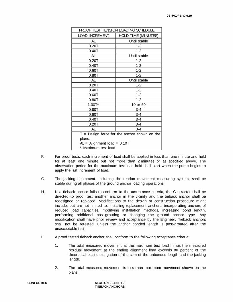
PROOF TEST TENSION LOADING SCHEDULE LOAD INCREMENT HOLD TIME (MINUTES)
AL Until stable 0.20T 1-2 0.40T 1-2
AL Until stable 0.20T 1-2 0.40T 1-2 0.60T 1-2 0.80T 1-2
AL Until stable 0.20T 1-2 0.40T 1-2 0.60T 1-2 0.80T 1-2 1.00T* 10 or 60 0.80T 3-4 0.60T 3-4 0.40T 3-4 0.20T 3-4
AL 3-4 T = Design force for the anchor shown on the plans. AL = Alignment load = 0.10T * Maximum test load
F. For proof tests, each increment of load shall be applied in less than one minute and held for at least one minute but not more than 2 minutes or as specified above. The observation period for the maximum test load hold shall start when the pump begins to apply the last increment of load.
G. The jacking equipment, including the tendon movement measuring system, shall be stable during all phases of the ground anchor loading operations.
H. If a tieback anchor fails to conform to the acceptance criteria, the Contractor shall be directed to proof test another anchor in the vicinity and the tieback anchor shall be redesigned or replaced. Modifications to the design or construction procedure might include, but are not limited to, installing replacement anchors, incorporating anchors of reduced load capacities, modifying installation methods, increasing bond length, performing additional post-grouting or changing the ground anchor type. Any modification shall have prior review and acceptance by the Engineer. Tieback anchors shall not be retested, unless the anchor bonded length is post-grouted after the unacceptable test.
I. A proof tested tieback anchor shall conform to the following acceptance criteria:
1. The total measured movement at the maximum test load minus the measured residual movement at the ending alignment load exceeds 80 percent of the theoretical elastic elongation of the sum of the unbonded length and the jacking length.
2. The total measured movement is less than maximum movement shown on the plans.
05-PCJPB-C-029
CONFORMED SECTION 02455-11 TIEBACK ANCHORS
3. The creep movement between one and 10 minutes is less than 0.04-inch or the creep rate is less than 0.08-inch/log cycle from 6 to 60 minutes and has a linear or decreasing creep rate.
4. Failure does not occur at the maximum test load. Failure is defined as a slope of the load versus deflection (at end of increment) curve exceeding 0.025 inches/kip.
END OF SECTION

05-PCJPB-C-029
CONFORMED SECTION 02810-1 CHAIN LINK FENCE
SECTION 02810
CHAIN LINK FENCE
Caltrain Standard Specification Section 02810, Chain Link Fence, is invoked for this contract.
END OF SECTION
05-PCJPB-C-029
CONFORMED SECTION 03100-1 CONCRETE FORMING
SECTION 03100
CONCRETE FORMING
Caltrain Standard Specification Section 03100, Concrete Forming, is invoked for this contract.
END OF SECTION
05-PCJPB-C-029
CONFORMED SECTION 03150-1 CONCRETE ACCESSORIES
SECTION 03150
CONCRETE ACCESSORIES
Caltrain Standard Specification Section 03150, Concrete Accessories, is invoked for this contract.
END OF SECTION
05-PCJPB-C-029
CONFORMED SECTION 03170-1 CONCRETE FINISHING
SECTION 03170
CONCRETE FINISHING
Caltrain Standard Specification Section 03170, Concrete Finishing, is invoked for this contract.
END OF SECTION
05-PCJPB-C-029
CONFORMED SECTION 03200-1 CONCRETE REINFORCING
SECTION 03200
CONCRETE REINFORCING
Caltrain Standard Specification Section 03200, Concrete Reinforcing, is invoked for this contract.
END OF SECTION
05-PCJPB-C-029
CONFORMED SECTION 03300-1 CONFORMED CAST-IN-PLACE CONCRETE
SECTION 03300
CAST-IN-PLACE CONCRETE
Caltrain Standard Specification Section 03300, Cast-In-Place Concrete, is invoked for this contract.
END OF SECTION
05-PCJPB-C-029
CONFORMED SECTION 05200-1 STRUCTURAL STEEL
SECTION 05200
STRUCTURAL STEEL
Caltrain Standard Specification Section 05200, Structural Steel is invoked for this contract and modified as follows:
Part 2.03, Shop Finishing, is deleted in its entirety and replaced with the following: 2.03 GALVANIZING
A. Fabricate units complete or in largest practical sections before galvanizing. Thoroughly clean welded areas prior to galvanizing. Remove weld spatter, burrs, oil, grease and any other deleterious matter that would interfere with the adherence of the zinc.
B. Hot-dip galvanize products after fabrication (including shearing, punching, bending,
forming or welding) in accordance with ASTM A123. C. The weight of zinc coating shall be not less than 2.0 ounces per square foot of surface
area.
Part 3.02, Field Finish, is deleted in its entirety and replaced with the following: 3.02 FIELD TOUCH-UP
A. Galvanized surfaces that are abraded or damaged at any time after the application of the zinc coating shall be repaired by thoroughly wire brushing the damaged areas and removing loose and cracked coating, after which the cleaned areas shall be painted with 2 applications of unthinned zinc-rich primer (organic vehicle type) conforming to Caltrans Standard Specification Section 91, “Paint.” Aerosol cans shall not be used.
END OF SECTION