· pdf filefrom jerry smit sent thursday september 27 2012 509 pm to [email protected]...
TRANSCRIPT

From Jerry Smit
Sent Thursday September 27 2012 509 PMTo [email protected] [email protected]
Cc Decker Lee Richard Mendolia
Subject draft fact sheet and temporary aquifer protection permit for your review
Attachments 5565 6DraftFactsheet September 272012_.doc55656 DraftTAPP September27 20 12_.doc
Ms Maguire and Mr Johnson
Please find draft revised APP and fact sheet for your review will be in the office to 600pm if you would like to
contact me
Jerry Smit RG ManagerGroundwater Section
Water Quality Division
602-771-4827
SWVP-020971

EE Fact SheetAquifer Protection Permit P-i 06360
Place ID i579 LTF 55656
Arizona Department Temporary APP
of Environmental Florence Copper Project
The Arizona Department of Environmental Quality ADEQ has issued Temporary
Individual Aquifer Protection Permit APP for the subject facility that is valid for one
year and may be renewed for one additional year unless suspended or revoked
pursuant to Arizona Administrative Code A.A.C Ri8-9-A2i0E
This permit shall become effective upon the later of the following completion of the
public participation requirements final decision of the water quality appeals board of an
appeal or upon notification to ADEQ by the permittee that Curis can use the
authorization to operate the Production Test Facility PTF
This document gives pertinent information concerning the issuance of the permit The
requirements contained in this permit will allow the permittee to comply with the two key
requirements of the Aquifer Protection Program meet Aquifer Water Quality
Standards AWQS at the Point of Compliance POC and demonstrate Best Available
Demonstrated Control Technology BADCT
FACILITY INFORMATION
Name and Location
Permittees Name Curis Resources Arizona Inc
Mailing Address i575 Hunt Highway
Florence AZ 85i32
Facility Name and Location Curis Resources Ltd-Florence Copper Project
i575 Hunt Highway
Florence AZ 85i32
Re2ulatory Status
On March 20i2 ADEQ received an application for Temporary Individual Aquifer
Protection Permit APP from Curis Resources Inc for the copper mine historically
known as the Florence Copper Project
Facility Description
The PTF will occupy approximately i3.8 contiguous acres Curis proposes to
construct and operate the PTF over two-year period consisting of i4 month
leaching phase and month rinsing phase The PTF will contain total of 24 wells
and consist of Underground Injection Control UIC Class III injection wells
recovery wells observation wells and multilevel sampling wells The proposed
SWVP-020972

APP Fact Sheet Page of
Florence Copper Project
In-Situ Copper Recovery ISCR process involves injecting lixiviant 99.5% water
mixed with 0.5% sulfuric acid through injection wells into the oxide zone of the
bedrock beneath the site for the purposes of dissolving copper minerals from the ore
body The estimated injection zone is between approximately 500 feet below ground
surface ft bgs to 1185 ft bgs The resulting copper-bearing solution will be pumped
by recovery wells to the surface where copper will be removed from the solution in
solvent extraction electro winning SXEW plant The barren solution from the
SXEW plant will be reacidified and re-injected back into the oxide zone Other
facilities proposed for the PTF will include SXEW Plant Water Impoundment
Runoff Pond tank farm and other ancillary facilities The permitted facilities for the
Pilot Test include the following
The Process Water Impoundment PWI is used to evaporate neutralized solutions
and contain resulting sediments The PWI shall be located immediately north of
the runoff pond which is directly north of the SXEW plant The PWI shall be
designed as double liner system and include leak collection and removal
system LCRS The liner system shall consist o1 from bottom to top
compacted sub-grade foundation with liner bedding 60-mil HDPE secondary
liner geonet and 60-mil primary liner The LCRS shall be equipped with sumplocated at the lowest elevation of the pond sump pump to remove accumulated
liquids and an alarm system for fluid detection
The Runoff Pond is non-stormwater pond and shall be located directly south of
the PWI north of the adjacent SXEW plant and northeast of the Pregnant
Leachate Solution PLS and Raffinate tank secondary containment structure The
Runoff Pond is designed to capture direct precipitation stormwater runoff from
the roofs of on-site structures cathode storage slab and concrete apron on the
south side of the SXEW Building fire sprinkler water or process solutions that
may enter or overflow the SXEW Building floor sump and any spills on or
washed down from these areas The Runoff Pond shall be designed with single
liner that includes an engineered compacted sub-grade and 60-mil HDPE
geomembrane liner The Runoff Pond shall incorporate sump equipped with
pump along with fluid-level detection equipment When fluid is detected above
the level set-point the pump will transfer fluid out of the Runoff Pond to the PWI
via pipeline
The In-situ Area Injection and Recovery Well Block will contain total of 24
wells and consist of injection wells recovery wells observation wells and
multilevel sampling wells The injection wells at the site are classified as Class
III Injection wells by the USEPA and are permitted by the UIC Program The
injection and recovery wells will be designed to meet the mechanical integrity
requirements in the UIC regulations Code of Federal Regulations CFR part 144
and 146 All injection wells and recovery wells will be designed and installed to
prevent injection into the top 40 feet the exclusion zone of the oxide zone The
injection and recovery of the solutions will be limited to the Oxide ore body
SWVP-020973

APP Fact Sheet Page of
Florence Copper Project
II BEST AVAILABLE DEMONSTRATED CONTROL TECHNOLOGYThe design of the permitted facilities mentioned above has been evaluated and
determined to satisfy the requirements of A.A.C R18-9-A202 Detailed descriptions
of each facilitys BADCT are listed in Section 2.2.1 and Table 4.1-1 of the
Temporary APP
The PTF operation relies on hydraulic control of the ISCR solutions to demonstrate
BADCT Hydraulic control will be confirmed through the use of observation wells to
maintain an inward hydraulic gradient An inward hydraulic gradient is measured by
water level elevations in injection recovery and observation wells The rates of
injection and recovery will be continuously monitored and controlled so that the total
volume of solution recovered will be greater than the volume of solution injected
averaged over 30-day period Automatic controls and alarms will be used in the
well field to ensure process upsets do not result in the loss of hydraulic control
Hydrologic control over the inject solutions will be maintained for the duration of the
pilot test and until the mine block meets APP closure criteria
The injection pressure from the Class III wells injection wells will be kept below the
fracture pressure of the oxide ore body fracture gradient of 0.65 pounds per square
inch per foot psi/ft of depth was established by field test data as being adequate to
prevent hydraulic fracturing of the bedrock
III COMPLIANCE WITH AQUIFER WATER QUALITY STANDARDSPollutant Management Area-
The permittee is required to show that pollutants discharged will not cause or
contribute to violation of aquifer water quality standards AWQS at the points of
compliance POC or if an AWQS for pollutant is exceeded in an aquifer at the time
of permit issuance that no additional degradation of the aquifer relative to that
pollutant and determined at the applicable POC will occur as result of the discharge
from the proposed facility The location of the POCs which show compliance with
aquifer water quality standards is determined by an analysis of the pollutant
management area PMA the discharge impact area DIA and locations and uses of
groundwater wells in the area The POC locations are selected to protect off-site uses
of groundwater to verify BADCT performance and to allow detection of potential
impact from the facility discharges
The PMA is described in A.R.S 49-244 as the limit projected in the horizontal plane
of the area on which pollutants are or will be placed The PMA includes horizontal
space taken up by any liner dike or other barrier designed to contain pollutants in the
facility If the facility contains more than one discharging activity the PMA is
described by an imaginary line circumscribing the several discharging activities The
PMA is defined by line circumscribing the PTF Well Field Water Impoundment
Runoff Pond and ancillary facilities
Discharge Impact Area-
SWVP-020974

APP Fact Sheet Page of
Florence Copper Project
The DIA is defined by A.R.S 49-201.13 The DIA means the potential aerial extent
of pollutant migration as projected on the land surface as the result of discharge
from facility The DIA was determined using groundwater modeling program
MODFLOW SURFACT The groundwater flow modeling was used to determine the
DIA five years after closure and cessation of hydraulic control at the PTF The
projected DIA was calculated for multiple model layers and assumed sulfate
concentration of 750 mg/L throughout the IRZ at the time of closure The greatest
aerial extent of sulfate migration was defined at sulfate concentration mg/L above
background Based on this modeling the maximum potential aerial extent of
migration during the five year post-closure period was approximately 150 feet from
the PTF well field in the lower oxide zone
Hydrology
The saturated geologic formations underlying the site have been divided into three
distinct water bearing units referred to the Upper Basin Fill Unit UBFU the Lower
Basin Fill Unit LBFU and the Oxide Bedrock Unit The UBFU consists of
unconsolidated to slightly consolidated sands and gravels with lenses of finer grained
material The unit ranges in thickness between 200 and 250 feet in thickness within
the ISCR area The upper portions of the UBFU are not saturated and form the lower
vadose zone which extended to depths to approximately 150 ft bgs The Middle Fine
Grained Unit IVIFGU consists of calcareous clay to silty sand approximately 20 to
30 feet thick and is not considered main water bearing unit at the site Beneath the
IVIIFGU is the Lower Basin Fill Unit LBFU The LBFU consists of coarse gravel
fanglomerate and breccia The LBFU ranges in thickness from 70 to 750 feet based
on the structural relief of the bedrock contact beneath the LBFU The LBFU in the
test area is approximately 80 feet thick Groundwater in this unit typically exhibits
confined to semi-confined conditions The bedrock underlying the LBFU study
consists of Precambrian quartz monzonite and Tertiary granodiorite porphyry The
bedrock unit is further divided into the upper Oxide zone and the lower Sulfide zone
The upper Oxide zone is approximately 200 to 1500 feet thick and is the geologic
formation targeted for in-situ mining Groundwater movement through the Oxide
bedrock unit is dominantly controlled by secondary permeability features such as
faults or fractures The Oxide Unit is fully saturated and exhibits confined to semi-
confined aquifer conditions The sulfide mineralization below the Oxide ore body is
of unknown lateral and vertical extent The Sulfide bedrock unit does not yield
appreciable quantities of water and is not targeted for in-situ mining at the PTF
Depth to groundwater is approximately 200 feet bgs Groundwater levels have
declined approximately an average of 65 feet over the past 15 years for each of the
water bearing units at the site The decline in water levels is attributed to
dissipation of recharge impulses associated with higher than normal flows in the
Gila River during the early 1990s Typical groundwater elevation fluctuations in the
UBFU range between and feet and between 10 to 15 feet but as much as 20 feet
in the LBFU and Oxide units
SWVP-020975

APP Fact Sheet Page of
Florence Copper Project
The groundwater flow direction is predominately to the northwest with some
variation depending on seasonal groundwater pumping from irrigation wells located
on and off-site During periods of sustained agricultural pumping groundwater flow
shifts to the west but reverts back to the locally dominant northwest flow direction
during non-pumping seasons These changes have been observed each year from
1995 to present and the seasonal shift in groundwater flow direction is most
pronounced in the LBFU and Oxide Zone water bearing zones The Gila River is the
principal source of groundwater recharge in the region and is the significant
hydrologic feature affecting groundwater flow direction near the site
Monitorin2 and Reportin2 Requirements
The permit requirements for discharge monitoring quarterly and semi-annual
compliance groundwater monitoring and operational monitoring are listed in the
Section 4.1 of the Temporary APP in Tables 4.1-2 through 4.1-8 All reporting shall
be submitted in accordance with Section 2.7
Points of Compliance
There are designated POC wells for the Florence Copper Project PTF all will be
monitored for both hazardous and non-hazardous substances The Temporary APP
requires both quarterly and semi-annual compliance groundwater monitoring at all
POC locations The parameters to be monitored are listed in Section 4.1 Tables 4.1-6
and 4.1-7 of the Temporary APP
GROUNDWATER MONITORING POINTS OF COMPLIANCE
Total ScreenedPOC ADWR Aquifer
Depth Latitude Longitude IntervalNo Unit
ft bgs ft hgs
_________ _______________POCs for InSitu Well Filed
______________ ______________
M14- III
GL55-549172 859 33 03 4.WN
15 77W778-838 LBFU
55-547813 615 33034.04N11126
554-594 LBFU16.40W
M22-55-55583 1140 330 03 4.53N
1110 26932-1130 Oxide
15.76W
55-555824 250 33034.51N11126
10-250 UBFU16.50W
TBD TBD TBD TBD 500-640 LBFU
M54-TBD TBD TBD TBD 660-1200 Oxide
POCs for Impoundments
jT TBD 276 TBD TBD 200-275 UBFU
TBD to be determined The monitoring well location and construction details are proposed
pending final installation of the wells The wells are to be installed in accordance with the permit
Compliance Schedule Section 3.0 at which minor/other permit amendment shall incorporate the
ADWR registration number total depth of well latitude longitude and screened interval of the
well once the well is installed
SWVP-020976

APP Fact Sheet Page of
Florence Copper Project
Additional Groundwater Monitorin2
For the purpose of this permit ADEQ has established use protection level UPL for
arsenic of 10 .ig/L which is consistent with EPAs primary drinking water standard
for arsenic The northwest corner of the State Mineral Lease Land on which the PTF
will be located has been conservatively designated as the down gradient point at
which the arsenic UPL will be applied Consistent with ADEQs substantive policy
statement titled Using Narrative Aquifer Water Quality Standards to Develop Permit
Conditions for Aquifer Protection Permits Oct 2003 an alert level for arsenic will
be establish for each of the POC wells see Section 3.0 Compliance Schedule
through consideration of fate and transport of arsenic to ensure that the UPL is not
exceeded at the northwest corner of the State Mineral Lease Land downgradient to
the PTF
Monitoring well MW-0 shall be located in the down gradient groundwater direction
at or near the PTF well field boundary The placement of MW-01 shall be
sufficiently located to measure changes in chemical groundwater concentrations
emanating from the injection zones within the effective time frames of the Temporary
APP MW-01 is required to be sampled prior to and after the pilot test for an
expanded list of parameters and on monthly basis for the duration of the pilot test
for pH sulfate and total dissolved solids TDS Monitoring well MW-01 shall be
installed and approved by ADEQ in accordance with the Compliance Schedule
Section 3.0
IV STORM WATER AND SURFACE WATER CONSIDERATIONSThe Permittee shall contain and control the run-on and run-off from 100-year 24-
hour storm event so that no contaminated storm water will discharge from the site
The Process Water Impoundment and Run-off pond will contain all storm water run-
on into the facility and all run-off generated within the facility
COMPLIANCE SCHEDULEThe Temporary APP includes an extensive compliance schedule requiring the
permittee to submit several items including initial discharge characterization
ambient groundwater quality monitoring data and well completion reports
VI OTHER REQUIREMENTS FOR ISSUING THIS PERMIT
Technical Capability
Curis Resources Ltd has demonstrated the technical competence necessary to carry
out the terms and conditions of the permit in accordance with A.R.S 49-243N and
A.A.C R18-9-A202B All documentation required by this amendment application
has been sealed accordingly
ADEQ requires that appropriate documents be sealed by an Arizona registered
geologist or professional engineer This requirement is part of an on-going
SWVP-020977
APP Fact Sheet Page of
Florence Copper Project
demonstration of technical capability The permittee is expected to maintain technical
capability throughout the life of the facility
Financial Capability
The permittee has demonstrated financial capability under A.R.S 49-243N and
A.A.C R18-9-A203 The permittee shall maintain financial capability throughout the
life of this permit The estimated closure cost is $3487743 The financial assurance
mechanism was demonstrated through performance surety bond A.A.C R18-9-
A203 C2Zonin2 Requirements
Mining activity of greater than five contiguous acres is exempt from zoning
requirements pursuant to A.R.S 11-8 12
VII PUBLIC PARTICIPATION
Public Participation for Temporary APPs A.A.C R18-9-210DThe Director shall postpone the public participation requirements under Ri 8-9-109
shall not postpone notification of the opportunity for public participation for more
than 30 days from the date of the temporary individual permit and may amend or
revoke the temporary individual permit after consideration of public comments
Public Comment Period A.A.C R18-9-109AThe aquifer protection program rules require that permits be public noticed in
newspaper of general circulation within the area affected by the facility or activity
and provide minimum of 30 calendar days for interested parties to respond in
writing to ADEQ After the closing of the public comment period ADEQ is required
to respond to all significant comments
Public Hearin2 A.A.C R18-9-109B
public hearing may be requested in writing by any interested party The request
should state the nature of the issues proposed to be raised during the hearing
public hearing shall be held if the Director determines there is significant amount of
interest expressed during the public comment period or if significant new issues arise
that were not considered during the permitting process
Public Notice A.A.C R18-9-108AThe public notice is the vehicle for informing all interested parties and members of
the general public of the contents of draft permit or other significant action with
respect to permit or application The basic intent of this requirement is to ensure
that all interested parties have an opportunity to comment on significant actions of the
permitting agency with respect to permit application or permit This permit shall be
public noticed in local newspaper after pre-notice review by the applicant and
other affected agencies
SWVP-020978
APP Fact Sheet Page of
Florence Copper Project
VIII ADDITIONAL INFORMATIONAdditional information relating to this proposed permit may be obtained from
Arizona Department of Environmental Quality
Water Quality Division Mining Unit
Attn Richard Mendolia
1110W Washington St Mail Code 5415B-3
Phoenix Arizona 85007
Phone 602 771- 4374
SWVP-020979

AQUIFER PROTECTION PERMIT NO P- 106360
of 42
STATE OF ARIZONA
TEMPORARY AQUIFER PROTECTION PERMIT NO P- 106360
PLACE ID 1579 LTF 55656
1.0 AUTHORIZATION
In compliance with the provisions of Arizona Revised Statutes A.R Title 49 Chapter Articles and Arizona
Administrative Code A.A.C Title 18 Chapter Articles and Title 18 Chapter 11 Article and amendments
thereto and the conditions set forth in this permit the Arizona Department of Environmental Quality ADEQ hereby
authorizes Curis Resources Arizona Inc to operate the Florence Copper Project- Pilot lest Facility Florence Pinal County
Arizona over groundwater of the Pinal Active Management Area in Sections 2ft 27 2K 33 34 and 35 Range 9E
Township 4S Gila and Salt River Base Line and Meridian
For purposes of A.A.C Ri 8-9-A2 10E this permit becomes effective on the later oithe bflo ing Jfno timely appeal is
filed upon completion of the public participation requirements under A.A.U R- --10 ía tiniel appeal is filed upon
final decision of the water quality appeals board or upon the date specified the perniittee in vritten notification to
ADEQ that the permittee can use the authorization to operate the PTF granted by this permit
Following all the conditions of this permit including the design and operational information docuniented or referenced
below and
Such that Aquifer Water Quality Standards AWQS are not violated at the applicable point of compliance POC set
forth below or if an AWQS for pollutant has been e\ceeded in an aquifer at the time of permit issuance that no
additional degradation of the aquifer relative to that pollutanL and as determined at the applicable POC occurs as
result of the discharge from the facility
1.1 PERMITTEE INFORMATION
Facility Name Florence Copper Project Production Test Facility
Facility Address Curis Resources Ari/olia Inc
1575W Hunt Highway
Florence AZ 85132
Permittee Curis Resources Arizona Inc
Permittee Address 1575 Hunt Highway
Florence AZ 85132
FaciIit Contact Dan Johnson Vice President Environmental
Emergency Phone No 52W 374-3984
Latitude/Longitude 3303 00N/ 111 25 00
Legal Description lownship 4S Range 9E Sections 26 27 28 33 34 and 35 NE NE SE of
the Gila and Salt River Base Line and Meridian
1.2 AUTHORIZING SIGNATURE
Michael Fulton Director
Water Quality Division
Arizona Department of Environmental Quality
Signed this _____day of 2012
SWVP-020980

AQUIFER PROTECTION PERMIT NO P- 106360
of 42
2.0 SPECIFIC CONDITIONS IA.R.S 49-2034 49-241A
2.1 Facility Site Description IA.R.S 49-243K8The Temporary Individual Aquifer Protection Permit APP is for Production Test Facility PTF pilot scale
test facility located on approximately 160 acres of the Arizona State Land Mineral Lease 11-26500 The
Temporary APP is to construct and operate production test facility which shall provide sufficient data to assess
and develop ftill-scale in-situ mining operation
The PTF will occupy approximately 13.8 contiguous acres and the PTF well field will occupy approximately 2.2
acres Curis Resources Arizona Inc proposes to construct and operate the PTF over two year period estimated
to include an approximate 14 month leaching phase and month mine block nnsing phase The PTF will contam
total of 24 wells and consist of Underground Injection Control UIC Class III injection wells recoveiywells
observation wells and multilevel sampling wells The proposed In Situ Copper Recovery ISCR process
involves injecting lixiviant 99 5% water mixed with 5% sulftinc acid through injection wells into the oxide
zone of the bedrock beneath the site for the purposes of dissolving copper minerals from the ore body The
estimated injection zone is between approximately 500 feet below ground surface ft bgs to 185 ft bgs The
resulting copper bearing solution will be pumped by recovery wells to the surface where copper will be removed
from the solution in solvent extraction electro winning SX/EW plant The barren solution from the SX/EW
plant will be re acidified and re injected back into the oxide zone Other facilities proposed for the PTF will
include the SX/EW Plant Process Water Impoundment PWI Runoff Pond tank farm ind other ancillary
facilities
The site includes the following permitted discharging facilities
FaeiIit Latitude Longitude
InSitu Area
Injection anti Recoer Well 3303 1.39 1110 26 4.69
Block
Process Water Inioundnient 3303 8.67 1110 25 22.18
Run-oil Pond 3303 4.66 1110 25 22.6
Annual Registration Fee 14 49-242 and R18-14-104
The annual registration fee for this permit is established by 49 242 and is payable to ADEQ each year
The design flow is 432 000 gallons per day gpd
Financial Capability IA 49-243N and R18-9-A203The permittee has demonstrated finsibial capability under A.R.S 49-243N and A.A.C R18-9-A203 The
permittee shall maintain financial capability throughout the life of this permit The estimated closure cost is
$3487743 The financial assurance mechanism was demonstrated through performance surety bond A.A.CR18-9-A203 C2
2.2 Best Available Demonstrated Control Technology IA.R.S 49-243B and A.A.C R18-9-A202A5This permit authorizes the temporary operation of the discharging facilities listed below pursuant to A.A.C Ri 8-9-
A2 10E The intent of the pilot test is to demonstrate that hydraulic control of the in-situ solution can be
maintained at the site in order to conduct copper recovery process The discharging facilities and their BADCT
descriptions are also presented in Section 4.1 Table 4.1-1
2.2.1 Engineering Design
2.2.1.1 In-Situ Area Injection and Recovery Well Block
Design construction testing mechanical integrity and operation of injection and recovery
wells shall follow EPA Class III rules 40 CFR Part 146 The maximum fracture pressure shall
SWVP-020981
AQUIFER PROTECTION PERMIT NO F- 106360
of 42
be no greater than 0.65 pounds per square inch per foot psi/ft of depth Hydraulic control
shall be maintained at all times within the pilot test facility well block by pumping recovery
wells at rate greater than the injection rate in order to maintain cone of depression The
injection and extraction volumes shall be metered at the well-heads monitored daily and
recorded Surface water control shall be provided for the PTF injection and recovery well sites
2.2.1.2 Process Water ImpoundmentThe Process Water Impoundment PWI process solution pond shall be used to evaporate
neutralized solutions and contain resulting sediments The PWI shall be located immediately
north of the runoff pond which is directly north of the SX/EW plant The PWI shall have
capacity of approximately 1.7 million cubic feet approximately 15 to 23-feet deep with internal
and external side slopes of 2.5-feet horizontal to 1.0-feet vertical 2.SH lv and maintain
minimum of two feet freeboard The PWI shall be designed as double liner system and
include leak collection and removal systeni IRS The liner system shall consist of from
bottom to top compacted sub-grade fouiidation ith liner bedding 60-mil HDPE secondaiy
liner geonet and 60-mil primary liner Ilie .CRS shall be equipped with sump located atthe
lowest elevation of the pond sunip pump to remo accumulated liquids and an alaim system
for fluid detection
2.2.1.3 Run-off Pond
The Runoff Pond non-stormwater pond shall be located directly south of the PWI north of
the adjacent SX/EW plant and northeast of the Pregnant .eachate Solution PLS and Raffmate
tank secondary containment structure The Runoti Polk shall be designed to capture direct
precipitation stormwater runoff from the roofs of on-site structures cathode storage slab and
concrete apron on the south side of the SX/EW 3uilding lire sprinkler water or process
solutions that may enter or overflow the SX/EW Building Iloor sump and any spills on or wash
down ioni these areas The Runoff Pond shall have capacity of approximately 6583 cubic
Uet appro\inlatel\ 5-feet deep internal and external side slopes shall be no less than 2.0-feet
luwiontal to .H-Uet vertical 2.SH1V and pond shall maintain minimum of two feet
ieeboard Ihe Runoli Pond shall be designed with single liner that includes an engineered
compacted sub-grade and 60-mil HDPE geomembrane liner The RunoffPond shall incorporate
sump equipped \\ ith pump along with fluidlevel detection equipment When fluid is
detected above the leve set-point the pmp will transfer fluid out of the RunoffPond to the PWI
via pipelme
2.2.2 Site-specific Characteristics
Not applicable to this permit
2.2.3 Pre-operational Requirements
All boreholes or wells other than those approved for the PTF located within 500-feet of the PTF well
field boundary shall be plugged and abandoned per the Arizona Department of Water Resources
ADWR rules and EPA Underground Injection Control UIC regulations prior to PTF operation
Documentation records for the plugging and abandonment of all boreholes and wells within 500 feet
of the PTF shall be submitted no later than 30 days prior to the start-up of the pilot study
All Class III injection wells shall be drilled cased and cemented according to the requirements of the
UIC permit Prior to commencement of operation all new Class III injection wells shall meet the
mechanical integrity testing MIT requirements of the UIC permit
The permittee shall complete aquifer pump tests prior to injection in order to optimize knowledge of
subsurface characteristics particularly within the targeted in-situ leaching zone and report in
accordance with Section 2.7.4.3
Inward hydraulic gradient towards the Recovery Wells shall be established prior to the injection of
acidified process solution into the injection wells
The permittee shall establish ambient mine block groundwater concentrations using an ADEQ
SWVP-020982

AQUIFER PROTECTION PERMIT NO F- 106360
of 42
approved statistical method see Section 2.7.4.2 to determine pre-mining concentrations at the PTF
wells in accordance with the Compliance Schedule Section 3.0
2.2.4 Operational Requirements
description of required inspections and operational monitoring for BADCT is included in Section 4.1
Table 4.1-3
The injection wells at the site are classified as Class III Injection wells by the USEPA and are permitted
by EPAs UIC Program The injection and recovery wells shall be designed to meet the mechanical
integrity requirements in the UIC regulations Code of Federal Regulations PR part 144 and 146 All
injection wells andrecovery
wells shall be designed and installed to pie ent injection into the top 40 feet
the exclusion zone of the oxide zone The injection and reco en of the solutions shall be limited to the
Oxide ore body only
The PTF operation relies on hydraulic control of the In-Situ Copper Reco en ISCR solutions to
demonstrate BADCT Hydraulic control shall be confirmed through the use ol observation wells to
maintain an inward hydraulic gradient An inward hydrologic gradient shall be measured by Vs Liter level
elevations in injection recovery observation wells The rates of injection and reco en shall be
continuously monitored and controlled so that the total volume of solution reco ered is greater than the
volume of solution injected averaged over 24 hour period Automatic controls and alarnis shall be used
in the well field to ensure process upsets do not result in the loss of hydrologic control Hydrologic
control over the injected solutions shall be maintained from the time injection begins and until well
abandonment is completed the applicant and approved by the appropriate agencies and groundwater in
the mine blocks meets APP closure criteria description of required operational monitoring is included
in Section 4.1 Table 4.1-8
The injection pressure in the Class III injection ells shall he kept below the fracture pressure of the
oxide ore body fracture gradient of O.h5 pounds squareinch
perfoot psi/ft of depth was
established by field test data as being adequate to pre ent Ii draulic fracturing of the bedrock The
injection pressures and maximum injection pressures at the injection wells will be deteimined subsequent
to injection well installation and will be required to be amended into the permit as part of the Compliance
Schedule Section 3.0
2.3 Discharge Limitations IA.R.S 49-20114 49-243 and A.A.C R18-9-A205BJThe peniuttee shall operate and maintain all permitted facilities listed below to prevent unauthorized discharges
pursuant to A.R.S 41-201J2 resulting from failure or bypassing of BADCT pollutant control technologies
induding liner failure uncontrollable leakage overtopping e.g exceeding maximumstorage capacity defmed as
Iluid le el e\ceeding the crest ele ation of permitted impoundment berm breaches accidental spills or other
unauthoricd discharges
2.3.1 In-Situ Area Injection and Recovery Well Block
draulic control O\ er the injected solutions shall be maintained during the operating life of the facility
In-situ sohutions shall be injected and contained within the oxide unit
2.3.2 Process Water ImpoundmentThe PWI shall be used to store neutralized solutions and resulting sediments and direct precipitation
2.3.3 Run-off Pond
The Runoff Pond shall be used to capture direct precipitation stormwater runoff from roofs on-site
structures cathode storage slab and concrete apron on the south side of the SX/EW building fire
sprinkler water or process solutions that may enter or overflow the SX/EW Building floor sump any
spills or wash down from these areas and process upset events
SWVP-020983

AQUIFER PROTECTION PERMIT NO P- 106360
of 42
2.4 Points of Compliance IA.R.S 49-244
The Points of Compliance POC are listed in Table below Monitoring shall be conducted at each Point of
Compliance POC as listed in Section 4.1 Table 4.1-6 and 4.1-7
Ml 5-
GU55-547813 615 330 03 4.04N iii
M54-TBD TBD TBD 1131 660-1200 Oxide
POCs for Impoundments
M52-TBD 276 TBD 1131 200-275 UBFU
UBF
Note TBD to be determined The monitoring well location and construction details are proposed pending
final installation ol the vs ells The wells are to be installed in accordance with the Compliance Schedule
Section at Vs hich minor/other permit amendment shall incorporate the ADWR registration number
total depth ol vs eli latitude longitude and screened interval of the well once the well is installed
The Director nm aniend this permit to designate additional POCs if information on groundwater gradients or
groundwater usage indicates the need
2.4.1 New Well Design anti Installation
The permittee shall submit design specilication forany
other wells that may be installed or modified for
ADEQs prior revievs and appro al The wells shall be designed with appropriate surface seals annular
seals to prevent cross contamination p1 ugs above the filter pack to prevent cement grout intrusion into the
filter pack and screen and lilter pack and screen size selected for the lithology of the screened interval
All new wells shall be developed after installation and allowed to recover at least one week prior to
collection of an initial groundwater sample
2.4.1.1 Well Installation Report
well installation report shall be submitted to ADEQ within 60 days after the completion of the
wells installation in accordance with Section 3.0 The well installation report shall be
completed in accordance with A.A.C Ri 2-15-801 et seq and consist of the following
Copies of Arizona Department of Water Resources ADWR Notice of Intent NOTand all related submittals to ADWRBoring log and well as-built diagram
Total depth of well measured after installation
Top of well casing or sounding tube whichever is used as the fixed reference
measuring point and ground surface elevation
Mi 4-
OL55-549172 859
POCs for In-Situ Well Filed
33 03 4.0N
M22-55-555831
iii026
M23
UBF
1140
55-555824
778-838
330 03 4.53N
M54-
LBF
LBFU
250
16.4
111 26 15.7
554-594
TBD
330 03 4.51
LBFU
TBD
n1130
TBD
1110 26 16.50W
Oxide
LI
1131 50 tO
UBFU
LBFU
SWVP-020984

AQUIFER PROTECTION PERMIT NO P- 106360
of 42
Depth to groundwater
Geophysical logging reports and subsurface sampling results if any
Description of well drilling method
Description of well development method
If dedicated sampling equipment installed details on the equipment and at what
depth the equipment was installed
Summary of analytical results for initial groundwater sample collected after
installation
Corresponding analytical data sheets and
GPS coordinates for each new well
2.4.1.2 Replacement Wells
In the event that well other than POC well should become unusable or inaccessible due to
damage significant decrease and/or increase in water level or any other event if replacement
well is installed it shall be approved by ADBQ
Monitoring Requirements IA 49-243B and K1 R18-9-A206AJAll monitoring required in this permit shall continue for the duration ofthe permit regardless ofthe status of the
facility Monitoring shall commence the first ftill monitoring period following permit issuance All sampling
preservation and holding times shall be in accordance with currently accepted standards ofprofessional practice
Trip blanks equipment blanks and duplicate samples shall also lx obtained and Chain of Custody procedures
shall be followed in accordance with currently accepted standards of professional practice The permittee shall
develop site specific Quality Assurance Project Plan QAPP that describes the sample collection and analysis
procedures to ensure that the result of work performed under this permit shall satisfy the data quality objectives of
the permit The permittee shall be responsible for the quality and accuracy of all data required by this permit If
third party collects or analyzes samples on behalf of the permittee the permittee shall obtain copy of the third
party site specific QAPP IIicpermittee shall consult with the most recent version of Title 40 PART 136 of the
Environmental Protection Agency EPA Code of Federal Regulations CFRfor guidance in this regard Copies
of laboratory analyses and Chain-of Custody forms shall be maintained at the permitted facility Upon request
these documents shall be made immediately available for review by ADEQ personnel
Discharge Monitoring
Discharge morntonng shall be conducted on one time basis at the PLS Tank Raffinate Tank Process
Water Impoundment and Runoff Pond in accordance with Section Table and the Compliance
Schedule in Section within 90 120 days of initial PTF start up in order to allow for accurate
representation of process solutions The underground workings shall be depth specific sampled before
the PTF operations begin during the injection phase at least sixth months into the mining phase one
month after the mining has teased one month after the rinsing phase and into the closure and post
closure monitoring period Results of the discharging monitoring shall be submitted to the GWS within
30 days from receipt of the laboratory analytical results
2.5.2 Facility Operational Monitoring
Facility-specific operational monitoring requirements are listed in Section 4.1 Table 4.1-3
2.5.3 Groundwater Monitoring and Sampling Protocols
Static water levels shall be measured and recorded prior to sampling Wells shall be purged of at least
three borehole volumes as calculated using the static water level or until field parameters pHtemperature and conductivity are stable whichever represents the greater volume If evacuation results
in the well going dry the well shall be allowed to recover to 80 percent of the original borehole volume
or for 24 hours whichever is shorter prior to sampling If after 24 hours there is not sufficient water for
sampling the well shall be recorded as dry for the monitoring event An explanation for reduced
pumping volumes record of the volume pumped and modified sampling procedures shall be reported
and submitted with the Self-Monitoring Report Form SMRF
SWVP-020985

AQUIFER PROTECTION PERMIT NO F- 106360
of 42
As an alternative method for sampling the permittee may conduct the sampling using the low-flow
purging method described in the Arizona Water Resources Center March 1995 Field Manual for Water
Quality Sampling Under this method the well must be purged until at least two indicator parameters
stabilize Indicator parameters shall include dissolved oxygen turbidity pH temperature and
conductivity
2.5.3.1 POC Well Installation
Groundwater monitor wells must be installed at POC locations M54-LBF M54-O and M52-
UBF in accordance with the Compliance Schedule Section 3.0
2.5.3.2 Ambient Groundwater Monitoring
Eight rounds of groundwater sampling are required to establish ambient oundwater quality
groundwater monitoring wells M54-LBF M54- and M52-1 3F and any other additional POCs
required to be installed as part of the Compliance Schedule Section .W ach ambient sample
shall be analyzed for the parameters listed in Section 4. Table I-S Alert levels and aquifer
quality limits shall be established as required in Sections 2.5.3.2 and 2.5.3.2.2
2.5.3.2.1 Alert Levels for POC Wells
ALs for POC wells will be calculated for all parameters with an established AWQS and for the
other sampling parameters listed as reserved in Section 4.1 Table and Table 4.1-7
within 30 days of receipt of the laboratory analyses for the final sampling round of the ambient
groundwater monitoring period br each POC well list in Section 2.4 The permittee shall
submit the ambient ground ater monitoring data in tabulated form to the ADEQ Groundwater
Section GWS for re Copies of all laboratory analytical reports field notes and the
Quality Assurance/Qualit Control QA/QC procedures used in the collection and analyses of
the samples for all parameters listed in Section Tables 4.1-6 and 4.1-7 shallbe submittedto
the GWS The permittee nm submit report ith the calculations for each AQL and AL
included in the permit for re ie and approval Al or the permittee may defer calculation
of the AQLs and ALs to the GWS The AQI .s and ALs shall be established and calculated by the
following formula or another valid statistical method submitted to GWS in writing and approved
for this permit by the GWS
Al KS
Where mean standard deviation and one-sided normal tolerance interval with
conlidence level Lieberman G.J 1958 Tables for One-sided Statistical Tolerance
Limits Industrial Quality Control Vol XIV No 10 Obvious outliers should be excluded from
the data used in the AL calculation
Ihe bUos ing criteria shall be met in establishing ALs in the permit for constituents with an
AWQSThe AL shall be calculated for parameter using the analyses from minimum of eight
consecutive sample rounds The permittee shall not use more than eight sample
rounds in the calculation
Any data where the practical quantification limit PQL exceeds 80% of the AWQSshall not be included in the AL calculation
If parameter is below the detection limit the permittee must report the value as less
than the numeric value for the PQL or detection limit for the parameter not just as
non-detect For those parameters the permittee shall use value of one-half the
reported detection limit for the AL calculation
If the analytical results from more than 50% of the samples for specific parameter are
SWVP-020986

AQUIFER PROTECTION PERMIT NO F- 106360
of 42
non-detect then the AL shall be set at 80% of the AWQSIf the calculated AL for specific constituent and well is less than 80% of the AWQSthe AL shall be set at 80% of the AWQS for that constituent in that well
The following criteria shall be met in establishing ALs in the permit for constituents without an
AWQThe AL shall be calculated for parameter using the analyses from minimum of eight
consecutive sample rounds The permittee shall not use more than eight sample
rounds in the calculation
If parameter is below the detection limit the permittee must report the value as less
than the numeric value for the PQL or detection limit for the parameter not just as
non-detect For those parameters the permittee shall use value of one-half the
reported detection limit for the AL calculation
2.5.3.2.2 Aquifer Quality Limits for POC Wells
AQLs for POC wells will be calculated kr each othe analytes for which numeric AWQS has
been adopted within 30 days of receipt ol the laborator analyses for the final sampling round of
the ambient groundwater monitoring period for each ft vs dl list in Section 2.4 For each of
the monitored analytes for which numeric AWQS has been adopted the AQL shall be
established as follows
If the calculated AL is less than the AWQS then the AQL shall be set equal to the
AWQSIf the calculated AL is greater than the AWQS then the AQL shall be set equal to the
calculated AL value and no AL shall be set tiw that constituent at that monitoring
point
2.5.3.3 QuarterI Compliance Monitoring
The pcniiittee shall perform quarterly compliance monitoring of the POC wells as specified in
Section 4. Table -6 The results of the monitoring shall be compared to the AQLs and ALs
lithe results indicate an exceedance of an AL or violation of an AQL then the permittee shall
compl ith Section 2..2.4 cceedmg of Alert Levels in Groundwater Monitoring or Section
2.7.3
The perniittee shall submit reports othe quarterly compliance monitoring in accordance with
the reporting schedule at Section 2.7.6
2.5.3.4 Semi-Annual Compliance Monitoring
The permittee shall perform semi-annual compliance monitoring of the POC wells as specified
in Section 4.1 Table 4.1-7 The results of the monitoring shall be compared to the AQLs and
ALs If the results indicate an exceedance of an AL or violation of an AQL then the permittee
shall comply with Section 2.6.2.4 Exceeding of Alert Levels in Groundwater Monitoring or
Section 2.7.3
The permittee shall submit reports of the semi-annual compliance monitoring in accordance
with the reporting schedule at Section 2.7.6
2.5.3.5 Point of Compliance Well Replacement
In the event that one or more of the designated POC wells should become unusable or
inaccessible due to damage or any other event replacement POC well shall be constructed
and installed upon approval by ADEQ If the replacement well is 50 feet or less from the
original well the ALs and/or aquifer quality limits AQLs calculated for the designated POCwell shall apply to the replacement well
SWVP-020987

AQUIFER PROTECTION PERMIT NO P- 106360
of 42
2.5.4 Surface Water Monitoring and Sampling Protocols
Surface water monitoring and sampling protocols are not applicable for this permit
2.5.5 Analytical Methodology
All samples collected for compliance monitoring and soil sampling shall be analyzed using Arizona state-
approved methods If no state-approved method exists thenany appropriate EPA-approved method shall
be used Regardless of the method used the detection limits must be sufficient to determine compliance
with the regulatory limits of the parameters specified in this permit Analyses shall be performed by
laboratory licensed by the Arizona Department of Health Services Office of Laboratory Licensure and
Certification For results to be considered valid all analytical work shall meet quality control standards
specified in the approved methods list of Arizona state-certified laboratories can be obtained at the
address below
Arizona Department of Health Services
Office of Laboratory Licensure and Certification
250 North 17th Avenue
Phoenix AZ 85007
Phone 602 364 0720
Installation and Maintenance of Monitoring Equtpment
Monitoring equipment required by this permit shall be installed and maintained so that representative
samples required by the permit can be collected If new groundwater wells are determined to be
necessarythe construction details shall be submitted to the ADEQ Groundwater Section for approval
prior to installation and the permit shall be amended to include any new points
Ml 5-
55-547813 615 33 03 4.04N 111 26 16.40W 554-594 LBFU
M22-55-55583 1140 330 03 4.53N 1110 26 15.76W 932-1130 Oxide
55-555824 250 33034.51N 1112616.50W 210-250 UBFU
UPL Total Screened
Welt ADWR No Depth Latitude Longitude IntervalAquifer
ft bgs ft bgs
2.5.7 Protection of Down
Forpurposes
which
coi1
desi
sub stantive
Conditions for
eachofthePOCv
of arsenic to ensure ti
radient Uses Arsenic
ut ADEQ has established use protection level UPL for arsenic of 10 mg/Lith EPA revised primary drinking water standard for arsenic The northwest
Lease Land on which the PTF shall be located has been conservatively
point at which the arsenic UPL will be applied ConsistentwithADEQs
Using Narrative Aquifer Water Quality Standards to Develop Permit
2003 an alert level for arsenic shall be established for
Section 3.0 through consideration of fate and transport
TPL is not exceeded at the northwest corner of the State Mineral Lease Land
Ml 4-
OL55-549172 859 3303 4.0N 11126 15.77W 778-838 LBFU
SWVP-020988

AQUIFER PROTECTION PERMIT NO F- 106360
10 of 42
GROUNDWATER MONITORING USE PROTECTION LEVEL WELLS
S4-1131 1131 1131 1131 5MMIA 1.I31I
M4-TBD TBD TBD TBD 60-120M Oxide
1131- to be determined The monitoring well location and construction details are proposed pending final
installation of the wells The wells are to be installed in accordance with the Compliance Schedule
Section 3.0 at which minor/other permit amendment shall incorporate the ADWR registration number
total depth of well latitude longitude and screened interval of the cIi once the well is installed
2.5.8 Monitoring Well
Monitoring well MW-0 shall be installed and approved Al iii accordance with the Compliance
Schedule Section 3.0 Monitoring well MW-0 shall he located in the do ii gradient groundwater
direction at or near the PTF well field boundary The placement of \V-fl shall he sufficiently located to
measure changes in chemical groundwater concentrations emanating from the injection zones within the
effective time frames of the Temporary APP MW-0 shall be nested well screened separately across
each proposed injection zone targeted for in-situ leaching and potentially into the 1.1 3lt MW-0 shall
be analyzed one month prior to the pilot test start-up and one month afier the rinsing phase for parameters
listed in Table 4.1-5 MW-0 shall be monitored monthly for the duration of the pilot test for pH sulfate
and total dissolved solids TDS The groundwater data collected for this well shall he summarized and
submitted as part of the Quarterl Reporting Requirement listed in Section 2.7.4.4
GROUNDWATER MONITORING WELL
Total ScreenedWell AquilerADWR No Depth Latitude Longitude Inter al
Unitift hgs ft hgs
O\lde
01TI 3D TI 31 TI 31 TI 31 TI 31 may include
________________ LBFU
2.6 Contingenç Plan Requirements
IA.R.S 49-243K3 K7 and A.A.C R18-9-A204 and R18-9-A205J
2.6.1 General Contingene Plan Requirements
At least one cop of this permit and the approved contingency and emergency response plans submitted in
the application shall he maintained at the location where day-to-day decisions regarding the operation of
the icility are made The permittee shall be aware of and follow the contingency and emergency plans
An AL that is e\cceded or any violation of an AQL discharge limit DL or other permit condition shall
he reported to Al following the reporting requirements in Section 2.7.3
Some contingency actions involve verification sampling Verification sampling shall consist of the first
follow-up saniple collected from location that previously indicated violation or the exceedance of an
AL Collection and analysis of the verification sample shall use the same protocols and test methods to
analyze for the pollutant or pollutants that exceeded an AL or violated an AQL The permittee is subject to
enforcement action for the failure to comply withany contingency actions in this permit Where
verification sampling is specified in this permit it is the option of the permittee to perform such sampling
If verification sampling is not conducted within the timeframe allotted ADEQ and the permittee shall
presume the initial sampling result to be confirmed as if verification sampling has been conducted The
permittee is responsible for compliance with contingency plans relating to the exceedance of an AL or
violation of DL AQL or any other permit condition
SWVP-020989

AQUIFER PROTECTION PERMIT NO F- 106360
11 of 42
2.6.2 Exceeding of Alert Levels
2.6.2.1 Exceeding of Alert Levels Set for Operational Conditions
If an Operational Conditions for BADCT in Section 4.1 Table 4.1-3 has been exceeded
the permittee shall
Notify the ADEQ Water Quality Compliance Section within five days of becoming
aware of violation of any permit condition in accordance with Section 2.7.3 Permit
Violation and Alert Level Reporting unless other reporting is specified in Section 4.1
Table 4.1-3
Submit written report within thirty 30 days after becoming aware of violation of
permit condition in accordance with Section 2.7.3 The report shall document all of
the following
description of the exceeded alue or performance standard and its cause
ii the period of violation including e\act dates and times if known and the
anticipated time period during vhich the iolation is expected to continue
iii any action taken or planned to mitigate the effects of the violation or the spill or
to eliminate or pre ent rccwence the iolation
iv any monitoring acti\ it\ or other miormation which indicates that any
pollutants would he reasonahl e\pccted to cause violation of an Aquifer
Water Quality Standard and
any malftinction or failure of pollution control devices or other equipment or
process
The facility is no longer on alert status once the operational indicator no longer indicates
that Operational Conditions is being exceeded Ihe perniittee shall however complete
all tasks necessary to return the facility to its pre-alert operating condition
2.6.2.2 Eweedanee of Alert Level for Normal Liner Leakage
If an Alert Level AL as specified in Section 4.1 Table 4.1-4 has been exceeded the
permittee shall take the following actions
Within da of discovery determine if the fluid in the collection sump is
operational/process \\ Liter froni the impoundment by measuring the pH and conductivity of
Ilwds in the impoundment and in the sump to allow direct comparison in wastewater
quality Noti\ ADFQ Water Quality Compliance Section in accordance with Section
2.7.31 Permit Violation and AL Status Reporting and include in the notification an
assessment ci the t\ peof water in the sump Monitor fluid removal from the LCRS on
daily basis until the daily volume of fluid quantified remains below AL1 for 30 days in
order to minimiie the hydraulic head on the lower liner
Within 15 da discovery assess the condition of the liner system using visual methods
for visible portions of the liner electrical leak detection or other methods as applicable to
determine the location of leaks in the primary liner If liner damage is evident the
permittee shall complete liner repairs and submit documentation of the repairs in the
initial report discussed in Item No below
Within 30 days of discovery of exceeding AL the permittee shall submit an initial
report to ADEQ Water Quality Compliance Section to address problems identified from
the initial assessment of the liner system the source of the fluid and any remedial actions
taken to minimize the ftiture occurrences The report shall include the results of the initial
liner evaluation methods used to locate the leaks if applicable any repair procedures
implemented to restore the liner to optimal operational status if required and other
information necessary to ensure the ftiture occurrence of the incidence will be minimized
The permittee shall also submit the report required under Section 2.7.3
For leakage rates that continue to exceed AL and are below AL Liner Leakage
Assessment Report shall be included in the next annual report described in Section 2.7.4
SWVP-020990

AQUIFER PROTECTION PERMIT NO F- 106360
12 of 42
Operational Other or miscellaneous Reporting of this permit The permittee may also
submit the Liner Leakage Assessment Report to the ADEQ prior to the annual report due
date This Liner Leakage Assessment Report shall be submitted to both the ADEQ Water
Quality Compliance Section and the ADEQ Groundwater Section
ADEQ will review the Liner Leakage Assessment Report and may require that the
permittee take additional action to address the problems identified from the assessment of
the liner and perform other applicable repair procedures as directed by the ADEQincluding repair of the liner or addressing and controlling infiltration of non-operational
water detected in the LCRS
2.6.2.3 Exceedance of Alert Level Discharge Limit for Liner Failure or Rips
If the Liner Leakage Discharge Limit AL specified in Section 4.1 Table 4.1-4 has been
exceeded the permittee shall
Immediately cease all discharge to the impoundment and notify ADEQs Water Quality
Compliance Section orally electronicall\ or by facsimile of the AlL exceedance
Within 24 hours determine iNs ater in the collection sump is operational/process water
from the impoundment nicasuring the p11 and conductivity of fluids contained in the
impoundment and in the sunip to allO\\ direct comparison in water quality
Within days of disco en notik Aft Water Quality Compliance Section in
accordance with Section 2.7.3 Permit viothtion and Al Status Reporting and include an
assessment regarding the type of water in the sump based upon the measurements taken
according to Item No listed above
Within 15 days of discovery identify the location oF the leaks using visual methods
electrical leak detection or other methods as applicable liner damage is evident the
permittee shall complete liner repairs and submit documentation of the repairs in Item
No below Discharge to the impoundment shall not be re-initiated until the leaks
ha been identified and repaired
Within IC da of exceeding AL submit report to ADEQ as specified in Section
2.7.3 Permit Violation and AL Status Reporting The report shall include the results of
the initial liner evaluation methods used to locate the leaks if applicable any repair
procedLLrcs and quaht assurance/quality control implemented to restore the liner to
optinlLd operatiollLd status it required and other information necessary to ensure the
luture occulTence othe incidence will be minimized Upon review ofthe report ADEQnm request additional momtoring or remedial actions
Ii Al continues to he exceeded following completion of repairs submit for approval
to Al conecti\ action plan including schedule to complete the corrective
actions to address all problems identified from the assessment of the liner system and
surtlice releases if any within 60 days of completion of repairs conducted in response to
Item Nt above Upon ADEQs approval the permittee shall implement the approved
plan and schedule of corrective actions
Within 30 days of completion of corrective actions submit to ADEQ written report as
specilied in Section 2.6.6 Corrective Actions
SWVP-020991

AQUIFER PROTECTION PERMIT NO P- 106360
13 of 42
2.6.2.4 Exceeding of Alert Levels in Groundwater Monitoring
2.6.2.4.1 Alert Levels for Indicator Parameters
If an AL in Section 4.1 Table 4.1-6 or Table 4.1-7 been exceeded the
permittee shall request that the laboratory verify the sample results within
days If the analysis does not confirm that an exceedance has occurred the
permittee may assume there has been no exceedance and no ftirther action is
required
Within days after receiving laboratory con lirmation of an AL being exceeded
the permittee shall notify the ADI Water Qualit compliance Section and
submit written confirmation \\ ithin 30 da\ receiving the laboratory
confirmation of an AL exceedance
If the results indicate an exceedance olan AL the permittee shall conduct
verification sample of ground ater iom the eli ithin 15 days from
laboratory confirmation If the erilication sample does not confirm that an
exceedance has occurred the permittee shall notit\ ADI Water Quality
Compliance Section of the results and assume there has been no e\ceedance
No ftirther action is required under this subsection
If verification sampling confirms that the AL has been e\ceeded the permittee
shall increase the frequency of monitoring to monthl and analyze for the
entire list olparameters listed in Section 4.1 Table 4.1-7 In addition the
pci-mi flee shall immediately investigate the cause of the exceedance and report
the results ol the in estigation with the 30 day confirmation noted above
AIDEQ ma\ require additional investigations the installation of additional
wells or correcti\ action in response to the report The permittee shall
continue monthl testing tbr the parameters until the parameters has
remained helo the Al for three consecutive monthly sampling events
2.6.2.4.2 Alert Levels for Pollutants with Numeric Aquifer Water Quality Standards
If an AL for pollutant set in Section 4.1 Table 4.1-6 and Table 4.1-7 has
been exceeded the perniittee may conduct verification sampling within days
of becoming aware an AL exceedance The permittee may use the results of
another sample taken between the date of the last sampling event and the date
of receiving the result as verification
If verification sampling confirms the AL exceedance or if the permittee opts
not to perform verification sampling then the permittee shall increase the
frequency of monitoring to monthly In addition the permittee shall
immediately initiate an investigation of the cause of the AL exceedance
including inspection of all discharging units and all related pollution control
devices review of any operational and maintenance practices that might have
resulted in an unexpected discharge and hydrologic review of groundwater
conditions including up gradient water quality
The permittee shall initiate actions identified in the approved contingency plan
referenced in Section 3.0 and specific contingency measures identified in
Section 2.6 to resolve any problems identified by the investigation which may
have led to an AL exceedance To implement any other corrective action the
permittee shall obtain prior approval from ADEQ according to Section 2.6.6
Alternatively the permittee may submit technical demonstration subject to
written approval by the Groundwater Section that although an AL is
exceeded pollutants are not reasonably expected to cause violation of an
AQL The demonstration may proposerevised AL or monitoring frequency
SWVP-020992

AQUIFER PROTECTION PERMIT NO F- 106360
14 of 42
for approval in writing by the Groundwater Section
Within 30 days after confirmation of an AL exceedance the permittee shall
submit the laboratory results to the Water Quality Compliance Section along
with summary of the findings of the investigation the cause of the AL
exceedance and actions taken to resolve the problem
Upon review of the submitted report the Department may amend the permit
to require additional monitoring increased frequency of monitoring or other
actions
The increased monitoring required as result of an AL exceedance may be
reduced to the regularly scheduled frequency if the results of three sequential
sampling events demonstrate that no parameters exceed the ALIf the increased monitoring required as result of an AL exceedance continues
for more than six sequential sampling events the permittee shall submit
second report documenting an investigation of the continued AL exceedance
within 30 days of the receipt ol laboratory results of the sixth sampling event
2.6.2.4.3 Alert Levels to Protect Dow ngradient Users from Pollutants Using
Narrative Aquifer Water Quality Standard
If an AL set br arseme iii Section Table 4.1-6 or 4.1-7 has been
exceeded the permittee shall conduct erilication sampling within days of
becoming aware of an Al e\cccdance
If verification sampling conlirms that the Al has been exceeded the
permittee shall investigate the cause ol the e\ceedance and shall submit
report regarding the exceedance to Al ithin 30 days of the date of
verification sample The report shall identiR the cause and sources of the
exceedance and shallpropose
actions to mitigate the exceedance The report
shall also present groundwater modeling to establish projected relationship
the wells in which exceedances were found and the downgradient
boundary of the Arizona State Land Department property at the facility
The permittee shall notii all downgradient users of the aquifer who may be
directl akcted the discharge within 24 hours of receiving the results of
verilication conhrniation sampling
2.6.2.5 Exceeding of BADCT Alert Le els for Injection/Recovery Well Operation
The permittee shall initiate the following actions within 24 hours of becoming aware ofanAlert
Level exceedance listed in Section 4.1 Table 4.1-8 for the loss of hydraulic control within the in-
situ leaching area for more than 24 consecutive hours loss of hydraulic control occurs when
the amount of fluids injected during 24 hour period exceeds the amount of fluid recovered for
the same 24 hour period Loss of hydraulic control is also indicated by flat or outward gradient
observed in any pair of observation and recovery wells over 24 hour period The permittee
shall
Notify the ADEQ Water Quality Compliance Section within one day of
becoming aware of the alert level exceedance
Adjust flow rates at injectionlrecovery wells until the recovery volume is greater
than the injected volume
Conduct an inspection testing of piping and wellhead for leaks injection and
recovery lines pumps flow meters totalizers pressure gauges pressure
transducers and other associated facilities
Review of recent process logs continuous chart recordings meter readings and
other operational control information to identifi any unusual occurrences
Initiatepressure testing of the appropriate wells if the loss of fluids cannot be
determined to be caused by surface facility failure and
SWVP-020993

AQUIFER PROTECTION PERMIT NO F- 106360
15 of 42
Repair system as necessary
Within one week submit report to ADEQ Water Quality Compliance Section The
report shall include but not be limited to providing the following information
injected volume in the period prior to the alert level exceedance recovered
volume in the period prior to the alert level exceedance corrective action taken
The permittee is no longer considered to be in violation if the injection rate and
recovery rates are re-established and maintained at normal operating conditions
following the completion of the corrective actions
If the exceedance of the Alert Level is determined to be result of planned disruption or power
outage the cause will be noted in the log book as required by Section 2.7.2
If leak is detected operation of the well shall cease until the leak has been repaired and
mechanical integrity demonstrated to mininiiie the potential for groundwater pollution
Within 30 days of the initial AL exceetlance caused leak the permittee shall submit report
to ADEQ OWS at the address shovs ii in Sect ion 2.7.5 Ibis report shall document all submittals
to EPA including but not limited to nionitormg and report data and reports checking
engineering and integrity of the ell
The facility is no longer on alert status once the operational indicator no longer indicates that an
AL is being exceeded The permittee shall lio C\ or coniplete all tasks necessary to return the
facility to its pre-alert operating condition
2.6.2.6 Exceeding of Alert Levels Set for Maximum Injection Pressure
The permittee shall initiate the following actions within 24 hours of becoming aware of an Alert
Level exceedance listed in Section 4.1 Table 4.1-8 br the exceedance of fracture gradient
The permittee shall
Immediately investigate to determine the cause of the AL being exceeded including
Inspection testing and assessment of the current condition of all components of
the injection system that may have contributed to the AL being exceeded which
may include taking the affected wells out of service and
Review of all data logger information test results and other operational control
information to identify any unusual occurrences
Repair system as necessary
Within 30 days of an AL being exceeded the permittee shall submit the related data to
the Al EQ Water Quality Compliance Section along with summary of the findings
ol the investigation the cause of the AL being exceeded and actions taken to resolve
the problem This report shall document all submittals to EPA including but not
limited to monitoring and report data and reports checking engineering and integrity
of the dl
pon review of the submitted report the Department may amend the peimit to require
atklitional monitoring increased frequency of monitoring amendments to permit
conditions or other actions
The facility is no longer on alert status once the operational indicator no longer
indicates that an AL is being exceeded The permittee shall however complete all
tasks necessary to return the facility to its pre-alert operating condition
SWVP-020994

AQUIFER PROTECTION PERMIT NO F- 106360
16 of 42
2.6.3 Discharge Limitations Violations
2.6.3.1 Liner Failure Containment Structure Failure or Unexpected Loss of Fluid
In the event of overtopping liner failure containment structure failure or unexpected loss of fluid
as described in Section 2.3 the permittee shall take the following actions
As soon as practicable cease all discharges as necessary to prevent any ftirther releases to
the environment
Within 24 hours of discovery notify ADEQ Water Quality Compliance Section
Enforcement Unit orally electronically or by facsiniilc
Within 24 hours of discovery of failure that resulted in release to the subsurface collect
representative samples of the fluid remaining in aiºcted impoundments and drainage
structures analyze samples according to Section Fable 4.1-2 and report in
accordance with Section 2.7.3 Permit Violation and Al Status Reporting In the 30-day
report required under Section 2.7.3 include cops otlie anabtical results andforwardthe
report to ADEQ Water Quality Compliance Section Enforcement nit and Groundwater
Section
Within 15 days of discovery initiate an evaluation to determine the cause flit the incident
Identify the circumstances that resulted in the failure and assess the condition of the
discharging facility and liner system Implement corrective actions as necessary to resolve
the problems identified in the evaluation Initiate repairs to an iiled liner system
structure or other component as needed to restore proper ftinctioning of the discharging
facility The permittee shall not resume discharging to the discharging facility until repairs
of any failed liner or structure are perlormed Repair procedures methods and materials
used to restore the stern to proper operating condition shall be described in the facility
log/recordkeeping ide and ailable br ADI re ieRecord in the facility log/rccordkeeping tile tile amount of fluid removed description of
the removal method and other disposal arrangements The facility log/recordkeeping file
shall be maintained according to Section 2.7.2 Operation Inspection Log/Recordkeeping
File
Within 30 days of discoven of the incident submit report to ADEQ as specified in
Section 2.7.3 Include description othe actions performed in Subsections through
listed above Upon review of the ieport ADEQ may request additional monitoring or
iemedial actions
Within 60 days of discovery conduct an assessment of the impacts to the subsoil and/or
gi-ounds ater resulting from the incident This assessment may include the installation of
the to determine down-gradient groundwater impact from the incident along with
commencement of groundwater monitoring perSection 4.1 Table 4.17 If soil or
groLlnd\\ Liter is impacted such that it could or did cause or contribute to an exceedance of
an AQI at the applicable point of compliance submit to ADEQ for approval corrective
action plan to address such impacts including identification of remedial actions and
schedule for completion of activities At the approval of ADEQ the permittee shall
implement the approved plan
Within 30 days of completion of corrective actions submit to ADEQ written report as
specified in Section 2.6.6 Corrective Actions
Upon review of the report ADEQ may amend the permit to require additional monitoring
increased frequency of monitoring amendments to permit conditions or other actions
2.6.3.2 Overtopping of Surface ImpoundmentIf overtopping of fluid from permitted surface impoundment occurs and results in discharge
pursuant to A.R.S 49-20102 the permittee shall
As soon as practicable cease all discharges to the surface impoundment to prevent any
SWVP-020995

AQUIFER PROTECTION PERMIT NO F- 106360
17 of 42
ftirther releases to the environment
Within 24 hours of discovery notify ADEQ Water Quality Compliance Section
Enforcement Unit
Within 24 hours collect representative samples of the fluid contained in the surface
impoundment Samples shall be analyzed for the parameters specified in Section 4.1
Table 4.1-2 Within 30 days of the incident submit copy of the analytical results to
ADEQ Water Quality Compliance Section Enforcement Unit
As soon as practicable remove and properly dispose of excess water in the impoundment
until the water level is restored at or below the appropriate freeboard as described in
Section 4.1 Table 4.1-3 Record in the facility log the amount of fluid removed
description of the removal method and the disposal arrangements The facility
log/recordkeeping file shall be maintained according to Section 2.7.2 Operation
InspectionlLogBook/Recordkeeping File
Within 30 days of discovery evaluate the cause of the overtopping and identify the
circumstances that resulted in the incident Implement corrective actions and adjust
operational conditions as necessan to resol the problems identified in the evaluation
Repair any systems as necessan to p1-c ent luture occurrences of overtopping
Within 30 days of discovers ol oertoppmg suhniit report to ADEQ as specified in
Section 2.7.3.2 Permit Violation and Alert I.e ci Status Reporting Include description
of the actions performed in Subsections through Ested above Upon review of the
report ADEQ may request additional niomtonng or remedial actions
Within 60 days of discovery and based on sampling in Subsection above conduct an
assessment of the impacts to the subsoil and/or ground Liter resulting from the incident
If soil or groundwater is impacted such that it could caLrsc or contribute to an exceedance of
an AQL at the applicable point of compliance submit to Al for approval corrective
action plan to address such impacts including identi ication of remedial actions and/or
monitoring and schedule for completion of acti\ ities At the direction of ADEQ the
permittec shall implement the approved plan
Within 30 da of completion of corrective actions submit to ADEQ written report as
specilied in Section 2.6.6 Corrective Actions Upon review of the report ADEQ mayamend the permit to require additional monitoring increased frequency of monitoring
amendments to permit conditions or other actions
2.6.3.3 InI1os of Unepeeted Materials to Surface ImpoundmentThe types olmaterials that are e\pected to be placed in the permitted surface impoundments are
specified in Section 2.3 Discharge Limitations Ifany unexpected materials flow to
permitted surice impoundment the permittee shall
As soon as practicable cease all unexpected inflows to the surface impoundments
Within 24-hours of discovery notify ADEQ Water Quality Compliance Section
Enforcement Unit
Within five days of the incident identify the source of the material and determine the
cause for the inflow Characterize the unexpected material and contents of the affected
impoundment and evaluate the volume and concentration of the material to determine if it
is compatible with the surface impoundment liner Based on the evaluation of the incident
repair any systems or equipment and/or adjust operations as necessary to prevent ftiture
occurrences of inflows of unexpected materials
Within 30 days of an inflow of unexpected materials submit report to ADEQ as specified
in Section 2.7.3.2 Permit Violation and Alert Level Status Reporting Include
description of the actions performed in Subsections through listed above
Upon review of the report ADEQ may amend the permit to require additional monitoring
increased frequency of monitoring amendments to permit conditions or other actions
including remediation
SWVP-020996

AQUIFER PROTECTION PERMIT NO F- 106360
18 of 42
2.6.3.4 Unexpected Loss of Fluid in the Injection/Recovery Wells at the PTFIn the event of an unexpected loss of fluid in the injectionlrecovery wells such that fluids are
released to the surface vadose zone or groundwater the permittee shall
Within two hours of discovery cease injection in the affected area and/or adjust flow rates at
injectionlrecovery wells until an inward hydraulic gradient is reestablished and excess
15CR solutions are recovered necessary to prevent ftirther releases to the environment
Operate the recovery wells in the affected area until the amount of fluid recovered is in
excess of the amount of fluid injected during the 24 hour period
Within 24 hours of discovery notify ADEQ WQCSInspect relevant components such as injection recovery lines pumps flow meters flow
totalizers pressure gauges pressure transducers and other associated facilities
Verify proper operations of all facilities vs ithin the in-situ leach area
Within 24 hours of discovery initiate an aluation to determine the cause for the incident
Identify the circumstances that resulted iii the lailure and assess the condition of the well
Implement corrective actions as riecessan to resolve the problems identified in the
evaluation Initiate repairs to an stem structure or other component as needed to
restore proper ftinctioning ol the ell The penhlittee shall not resume injecting or
discharging until repairs am uled structure are perlormed and tested as applicable
Repair procedures methods and materials used to restore the systems to proper operating
condition shall be described in the facilit log/recordkeeping file and available for ADEQreview The facilit lig/recordkeeping ide shall be maintained according to Section 2.7.2
Operation Inspection ogIRecordkeeping File
Submit written report vs ithin thins da to ADI as speciiied in Section 2.7.3 Permit
Violation and AL Status Reporting describing the incident and the corrective actions
taken Upon review oithe report the epartment nm require an amendmentto the peimit
to require surface vadose ione or grounds titer monitoring require installation of
additional POCs increased frequency momtoring remedial actions amendments to
permit conditions or other actions
Within 30 days of discovery conduct an assessment of the impacts to the surface vadose
zone and/or groundwater resulting ioni the incident If soil or groundwater is impacted
submit to ADEQ for approval corrective action plan to address such impacts including
identification of remedial actions and/or monitoring and schedule for completion of
acti\ ities The corrective action plan shall be submitted within sixty days of the incident At
the direction of ADEQ the permittee shall implement the approved plan
2.6.4 Aquifer Quality Limit Violation
Ian AQI br pollutant specified in Section 4.1 Table 4.1-6 and Table 4.1-7 is violated in POC
Well the permittee may conduct verification sampling no later than five days after learning of the
violation veriiication sampling does not verify the violation then the initial violation shall be
reported in the Quarterly Monitoring and Compliance Report and no ftirther action shall be required
the perniittee or that event
If erilication sampling confirms the violation or if the permittee opts not to perform verification
sampling then the permittee shall
Notift ADEQ within five days after confirming or learning of the violation in accordance
with Section 2.7.3A
Immediately initiate BADCT systems evaluation for the cause of the violation including
an inspection of all facilities regulated under this permit and corresponding pollution control
devices and review of any operational or maintenance practices that might have resulted in an
unexpected discharge and hydrogeologic assessment of the violation including
groundwater modeling review of groundwater conditions and up gradient water quality
groundwater contours and an inventory of downgradient well users and types of uses
SWVP-020997
AQUIFER PROTECTION PERMIT NO F- 106360
19 of 42
Increase the frequency of monitoring at the location of the violation to monthly
Submit written report based on the investigation within thirty 30 days after becoming aware
of the violation in accordance with Section 2.7.3 and
Take actions that may be necessary as result of the violation under Section 2.6.5
As part of its written report the permittee may include technical demonstration that the violation
was not caused or contributed to by pollutants discharged from facility regulated under this APPBased on the written report ADEQ may if
necessaryamend the permit to require increased
frequency of monitoring or additional monitoring and authorize corrective action including
measures to control the source of discharge causing the violation including BADCT correction if
necessary remediate affected soils surface water or grounds Liter and mitigate the impact of the
violation on existing uses of the aquifer ADEQs correcti\ act ion authori ation maybe inthe form
of an approval under Section 2.6.6 an amendment of this permit or appro al of contingency plan
If the violation continues for sixty 60 days then the permittee shall notii downgradient or
downstream users who may be directly affected by the jolation
If the violation continues for ninety 90 days then the pennittee shall prepare and submit for ADEQ
approval hydrogeologic investigation work plan within thirty alier recei ing the laboratory
results of the sixth sampling event The work plan shall assess whether the violation is due to natural
or anthropogenic causes and if exceeded values are found to be related to APP-regulated facilities
within the mine site or results are inconclusive the nature and extent of the discharge This
hydrogeologic investigation shall become the basis of adjusting permit conditions and/or designing
corrective action
2.6.5 Emergency Response and Contingene Requirements for Unauthorized Discharges pursuant
to A.R.S 49-20112 and pursuant to A.R.S 49-241
2.6.5.1 Duty to Respond
The permittee shall act irnrnediatel to correct am condition resulting from discharge
pursuant to AR 49-20 12 ii that condition couldpose an imminent and substantial
endangerment to public health or the environment
2.6.5.2 Discharge of Hazardous Substances or Toxic Pollutants
In the event ofany
unauthorized discharge pursuant to A.R.S 49-20102 of suspected
haardous substances A.R.S 4-20 119 or toxic pollutants A.R.S 49-243I on the
hcilit site the permittee shall promptly isolate the area and attempt to identif3i the discharged
material The permittee shall record information including name nature of exposure and
lollow-up medical treatment ifnecessary on persons
who may have been exposed during the
incident The permittee shall notii the ADEQ Water Quality Compliance Section within 24
hours upon discovering the discharge of hazardous material which has the potential to cause
an AWQS or AQL to be exceeded or could pose an endangerment to public health or the
environment
2.6.5.3 Discharge of Non-hazardous Materials
In the ent of any unauthorized discharge pursuant to AR 49-20112 of non-hazardous
materials from the facility the permittee shall promptly attempt to cease the discharge and
isolate the discharged material Discharged material shall be removed and the site cleaned up as
soon as possible The permittee shall notif3i the ADEQ Water Quality Compliance Section
within 24 hours upon discovering the discharge of non-hazardous material which has the
potential to cause an AQL to be exceeded or could pose an endangerment to public health
or the environment
2.6.5.4 Reporting Requirements
The permittee shall submit written report for any unauthorized discharges reported under
Sections 2.6.5.2 and 2.6.5.3 to ADEQ Water Quality Compliance Section within 30 days ofthe
SWVP-020998

AQUIFER PROTECTION PERMIT NO P- 106360
20 of 42
discharge or as required by subsequent ADEQ action The report shall summarize the event
including any human exposure and facility response activities and include all information
specified in Section 2.7 If notice is issued by ADEQ subsequent to the discharge
notification any additional information requested in the notice shall also be submitted within the
time frame specified in that notice Upon review ofthe submitted report ADEQ may require
additional monitoring or corrective actions
2.6.6 Corrective Actions
Specific contingency measures identified in Section 2.6 and actions identified in the approved contingency
plan referenced in Section have already been approved by ADEQ and do not require written approval
to implement
With the exception ofemergency response actions taken under Section 2.6.5 the permittee shall obtain
written approval from the Groundwater Section prior to implementing corrective action to accomplish
any of the following goals in response to exceeding AJ- or violation of an AQL DL or other permit
condition
Control of the source of an unauthorized discharge
Soil cleanup
Cleanup of affected surface waters
Cleanup of affected parts of the aquifer and/or
Mitigation to limit the impact of pollutants on existing uses of the aquifer
Within 30 days of completion ofany corrective action the operator shall submit to the ADEQ Water
Quality Compliance Section written report describing the causes impacts and actions taken to resolve
the problem
Reporting and Recordkeeping Requirements
IA 49-243K2 and R18-9-A206B and R18-9-A207J
Self-monibrmg Report Form
The permitS shall complete the SMRFs provided by ADEQ and submit them to the Water
Quality Compliance Section Data Unit
The permittee shall complete the SIVIIRF to the extent that the information reported may be entered on
the form If no information is required during reporting period the permittee shall enter not
required on the SMRF and submit the report to ADEQ The permittee shall use the format devised
by ADEQThe tables contained in Section 4.1 list the parameters to be monitored and the frequency for
reporting results for compliance monitoring Monitoring and analytical methods shall be recorded on
the SIVIIRFs
In addition to the SIVIIRF the information contained in A.A Ri 8-9-A206B shall be included
for exceeding an AL or violation of an AQL DL or any other permit condition being reported in the
current reporting period
2.7.2 Operation Inspection Log Book Recordkeeping
signed copy of this permit shall be maintained at all times at the location where day-to-day decisions
regarding the operation of the facility are made log book paper copies forms or electronic data of the
inspections and measurements required by this permit shall be maintained at the location where day-to
day decisions are made regarding the operation of the facility The log book shall be retained for tenyears
from the date of each inspection and upon request the permit and the log book shall be made
immediately available for review by ADEQ personnel The information in the log book shall include but
not be limited to the following information as applicable
SWVP-020999

AQUIFER PROTECTION PERMIT NO P- 106360
p.2 of 42
Name of inspector
Date and shift inspection was conducted
Condition of applicable facility components
Any damage or malftinction and the date and time any repairs were performed
Documentation of sampling date and time
Any other information required by this permit to be entered in the log book and
Monitoring records for each measurement shall comply with Ri 8-9 A206B2
2.7.3 Permit Violation and Alert Level Status Reporting
The permittee shall notify the Water Quality Compliance Section in writing within days except as
provided in Section 2.6.5 of becoming aware of violation of any permit condition discharge
limitation or of an AL exceedance
The permittee shall submit written report to the Water Quality Compliance Section within 30 days
of becoming aware of the violation of any permit condition or discharge limitation The report shall
document all of the following
Identification and description of the permit condition for which there has been violation and
description of its cause
The period of violation including exact dates and times if known and the anticipated time
period during which the violation is expected to continue
Any corrective action taken or planned to mitigate the effects of the violation or to eliminate or
prevent recurrence tue jolation
Any monitoring acti it or other inlorniation which indicates thatany pollutants would be
reasonably expected to cause vioiation an AWQSChanges to the monitoring \\hicll include changes ill constituents or increased frequency of
monitoring and
Description ofany
malftinction or iilure pollution control devices or other equipment or
processes
2.7.4 Operational Other or Miscellaneous Reporting
2.7.4.1 Annual Report
an Alert Level for Normal Liner Leakage has been exceeded discussed in Section 2.6.2.2
tile perniiflee shall submit an annual report that summarizes the results of the liner assessment
The .iner leakage Assessment Report shall also include information including but not limited
to the tollos ing number and location of holes identified table summarizing the ALl
exceetlunces including the frequency and quantity of fluid removed and corrective actions taken
The annual report shall be submitted prior to 30 days of expiration of this permit
2.7.4.2 Ambient Mine Block Concentration Report
Ambient mine block groundwater concentrations are required to be determined in order to
establish mine block closure rinsing requirements identified Section 2.9.1 One sample shall be
taken Irom each mine block well in order to establish ambient groundwater concentrations The
peniiittee shall submit within 30 days of completion of ambient mine block sampling the
ambient mine block groundwater concentrations
2.7.4.3 Results of Aquifer Pump Tests Prior to Operation of PTF
The permittee shall submit within 30 days of completion of aquifer pump test and prior to
beginning operation of the Pilot Study the results obtained from the aquifer pump test using
wells in and around the PTF in accordance with the Compliance Schedule Section 3.0 The
Aquifer Pump Test report shall discuss and evaluate the feasibility of the proposed Pilot Test
using data obtained from pump tests at the PTF wells The evaluation shall verify previously
SWVP-021000

AQUIFER PROTECTION PERMIT NO F- 106360
p.22 of 42
calculated aquifer properties such as hydraulic conductivity transmissivity groundwater
velocity etc and the validity of the porous medium assumption used in the groundwater
modeling for the oxide unit
2.7.4.4 PTF Operations and Monitoring Quarterly Reports
The permittee shall submit quarterly reports concerning the operations and monitoring of the
PTF during the 14-month mining and 9-month rinsing phase to the ADEQ Groundwater Section
GWS Quarterly reports shall be submitted no later than 30 days following the end of each
calendar quarter The quarterly report shall demonstrate heftier the hydraulic control was
maintained at the PTF during the quarterly monitoring period draulic control shall be
demonstrated by including but not limited to the follo ing continuous inward hydraulic
gradient by pumping more solution out than went in maintaining the fracture gradient and
compliance with ALs and AQLs at the POCs The report shall include
graphical representation of the volumes e\tracted and miected used to maintainhydraulic
control In the event that more solution was injected than recovered for 24-hour period
or in the event that any of the instruments used to measure the los\ volunies nialftinction or
are out of service for more than 24 consecutive hours the permittee shall submit report
showing for each day of the quarterly reporting period the Ii drafflic gradient was
maintained
graphical representation that continuous inward hydraulic gradient vs as maintained
using water le el ele ations in the PTF The reports shall include graphical presentation
of head comparisons tbr each pair of observation and recovery wells used to monitor the
hydraulic gradient The report shall also include figure showing the location and identity
of each of the paired vs ells In the ent an one of the well pairs indicate flat or outward
hydraulic gradient br 24-hour period or in the ent that any of the instruments used to
measure the hydraulic gradient malilinction or are out of service for more than 24
consecutive hours the perniiu.ee shall submit report showing for each day ofthe quarterly
reporting period the dail los\ into and out the mine block
summary of pressure transducers readings and fracture gradients readings
graphical representation of electric conductivity readings from the injection and
observation wells
description of any deviations Ironi standard sampling protocols during the reporting
period
summary of all exceedances of Ats AQLs Action Levels DLs or operational limits that
occulTed during the reporting period and provide the contingency actions completed to
mitigate the effects of the violation or to eliminate the recurrence of the exceedance or
iolation Ihe report shall also include identification and discussion of any laboratory
resifits that fell outside of the laboratory QA/QC criteria and AQLs and Ats required by
this permit
Graphical time versus concentration plots of groundwater elevations field pH sulfate and
total dissolved solids since the inception of monitoring at each POC well and any
piraiiieter which exceeded an applicable AL or AQL in the past three sampling events at
each POC well
Groundwater elevation contour maps for each quarterly monitoring period including the
groundwater elevation obtained from the underground workings The contour maps shall
identify if known any wells that were pumping within half-mile radius of the PTF
Results of the discharge characterization of the underground working if the required
sampling event falls within the quarterly reporting period
10 Fissure inspection summary for the reporting period
11 An updated table of all monitor wells in the Discharge Impact Area including but not
limited to location of well depth of well depth to water and water level elevation
12 summary ofany groundwater monitor wells replaced in the reporting period including
SWVP-021001

AQUIFER PROTECTION PERMIT NO F- 106360
p.23 of 42
but not limited to location of well depth of well depth to water water level elevation and
screened interval
13 Groundwater sampling results for the POCs and Monitor Wells
2.7.4.5 Well Abandonment Reports
If monitor wells associated with this permit are abandoned due to poor performance casing
collapse or other reasons or are abandoned at the end of the post-closure period then within 90
days of completing abandonment the permittee shall submit well abandonment report to
ADEQ Groundwater Section Appropriate contents of the report shall be sealed by an Arizona
professional geologist or professional engineer in accordance with Arizona Board of Technical
Registration requirements Well abandonment records shall be provided to ADEQ within 90
days of monitor well abandonment and shall include
Copies of ADWR Notice of Intent to Abandon
Copies of ADWR Abandonment Reports
description of the methods used to seal the vs dl casing and the perforated or screened
interval of the well and
Global Positioning System IFS coordinates ol the former well location
2.7.5 Reporting Location
All SIVIIRFs shall be submitted to
Arizona Department of Environmental Quality
Water Quality Compliance Section Data Unit
Mail Code 5415B-1
1110 Washington Street
Phoenix AZ 85007
Phone 602 771-4513
All documents required this permit to be submitted to the Water Quality Compliance Section shall be
directed to
Ariona cpartnient oil nvironmental Quality
Water Qualit omphance Section
Mail Code 541513-I
1110 Washington Street
Phoenix A/ 45Mfl7
Phone 602 77 -447
All documents required this permit to be submitted to the Groundwater Section shall be directed to
Arizona Department of ironmental Quality
Groundwater Section
Mail Code 5415B-3
1110 Washington Street
Phoenix AZ 85007
Phone 602 771-4428
2.7.6 Reporting Deadline
The Quarterly Report required by Section 2.7.4 and the results of monitoring conducted during each
quarter is due within 15 days of the end of the Pt quarter andevery quarter thereafter The signature date
of the permit shall be used for the purpose of determining the beginning of the Pt quarter to begin
monitoring and reporting
The following table lists the report due dates1
SWVP-021002

AQUIFER PROTECTION PERMIT NO F- 106360
p.24 of 42
Monitoring conducted during Quarterly Report due by
First Quarter January-March April 30
Second Quarter/Semi-Annual April-June July 30
Third Quarter July-September October 30
Fourth Quarter/Annual October-December January 30
1A post-mark date no later than the due date is considered meeting the due date requirements under this
Section
2.7.7 Changes to Facility Information in Section 1.0
The Groundwater Section and Water Quality Compliance Section shall be notified within 10 days of any
change of facility information including Facility Name Permittee Name Mailing or Street Address
Facility Contact Person or Emergency Telephone Number
2.8 Temporary Cessation 49-243K8 and A.A.C R18-9-A209AJThe permittee shall give written notice to the Water Quality Compliance Section Office before ceasing operation of
the facility for period of 60 days or greater The permittee shall take the following measures upon temporary
cessation
Immediately following ADEQ approval the permittee shall implement the approved plan If the permittee intends
to permanently cease operation of any facility the permittee shall submit closure notification as set forth in Section
2.9 below
At the time of notification the permittee shall submit for ADEQ approval plan for maintenance of discharge
control systems and for monitoring during the period of temporary cessation Immediately following ADEQ
approval the permittee shall implement the approved plan If necessary ADEQ shall amend permit conditions to
incorporate conditions to address temporary cessation During the period of temporary cessation the permittee shall
provide written notice to the Water Quality Compliance Section Office of the operational status of thefacility every
ninety days If the permittee intends to permanently cease operation of any facility the permittee shall submit
closure notification as set forth in Section 2.9 below
2.9 Closure IA.R.S 49-243K6 49-252 and A.A.C R18-9-A209BJFor facility addressed under this permit the permittee shall give written notice of closure to the Water Quality
Compliance Section of the permittee intent to cease operation without resuming activity for which the facility was
designed or operated or submit an amendment application to incorporate the discharging facilities under this
permit into the current individual permit Inventory Number P-i 01704 LTF Number 53498 dated August 12
2011
2.9.1 Closure Plan
Within 90 days of issuance of this permit the permittee shall submit for approval to the Groundwater
Section Closure Plan which meets the requirements of A.R 49-252 and A.A.C Ri 8-9-A209B3
and includes the following topics
Updated closure and post-closure financial requirements
Contingency mine block rinsing and sampling as needed
Confirmation PTF mine block sampling requirements after the completion of the pilot test
Confirmation underground workings sampling requirements after the completion of the pilot test
Outline of Report contents for PTF Summary Report which includes updated groundwater modeling
at the cessation of the pilot test
An initial year post-closure groundwater monitoring period with an evaluation to complete
SWVP-021003

AQUIFER PROTECTION PERMIT NO F- 106360
p.25 of 42
additional post-closure monitoring
Year Post-Closure Groundwater Monitoring Report including updated groundwater modeling
2.9.2 PTF Mine Block Closure
The permittee will commence PTF closure after the pilot test mining phase has ceased During mine block
closure operations the permittee will cease the injection of raffinate and will initiate mine block rinsing
program consisting of the injection of formation water and neutralization agents At all times during initial
block rinsing the permittee will maintain hydraulic control by sustaining an inward hydraulic gradient
within the mine block The permittee will monitor the rinsing progress anal i.ing the water recovered
from well-field headers for sulfate concentration When levels 5LLIate iii the headers have reached
approximately 750 parts per million the permittee will sample the injection well header discharges for
constituents listed in Section 4.1 Table 4.1-7 If the results of the saniphng show concentrations of
parameters greater than the AWQS and or greater than the pre-detennined mine block concentrations
above an AWQS then rinsing operations will continue until all compowids are below primary MCLs or
AWQS or predetermined concentrations
The permittee will sample all of the wells in the mine block undergoing closure to determine if the sulfate
concentrations are less than 750 ppm and the pH is above 5.0 S.U The permittee Vs ill continue rinsing
each well until such time that the sulfate concentration in the well is less than 750 ppni and the pH is
above S.U
When all individual well sulfate concentrations in the mine block are less than 750 ppm and pH is above
5.0 S.U hydraulic control will be discontinued for 30 days At the end of the 30-day period the headers
will be re-sampled and if sulfate concentrations remain below 750 ppm and pH of 5.0 S.U the peimittee
may cease all rinsing activities ithin the FTP All wells will continue to be monitored in
accordance with Section 2.5.3.3 and 2.5.3.4
confirmation groundwater sample of the FTP mine block vs ells vs ill be required at one month period
six month period and at the one year increment after the groundvs ater rinsing has ceased to measure any
rebound effects to mine block contaminant concentrations br constituents listed in Section 4.1 Table 4.1-
The results of the confirmation mine block sampling shall be submitted to ADEQ GWS within 30 days
of receiving the laboratory analytical results The permittee shall amendment APP P-b 1704 to
incorporate the required mine block closure con irmation sampling which extends beyond the permitted
time li-ames alloys ed by the Temporary APP pilot project
The FTP mine block vs ells shall be abandoned in accordance with ADWR regulations EPA and ADEQVs ritten approval shall be obtained prior to abandoning PTF mine block wells
2.10 Post-closure IA.R.S 49-243K6 49-252 and A.A.C R18-9-A209CJ
Post-closure requirements shall he established based on the approval of Closure Plan submitted to ADEQ per
Section 2.
SWVP-021004

AQUIFER PROTECTION PERMIT NO F- 106360
p.26 of 42
3.0 COMPLIANCE SCHEDULE IA.R.S 49-243K5 and A.A.C R18-9-A208J
For each compliance schedule item listed below the permittee shall submit the required information including cover
letter that lists the compliance schedule items to the Groundwater Section copy of the cover letter must also be
submitted to the Water Quality Compliance Section
Submittals Not Requiring Permit Amendments
Description Comments Due Date
Permittee shall submit cops signed dated and sealed as Within da
built dra ings along with QA/QU documentation to confirm completion of
that all discharging facilities were constructed in accordance construction of the PTF
ith the design report engineering plans and specifications
and other associated data and information approved by ADEQPermittee shall submit copy of the initial aquifer pump test Within 30 days of
results for the PTF wells to the ADEQ Groundwater Section for completion of
review construction and prior
to beginning operation
oithe PTF
Permittee shall submit ambient mine block groundwater Within 30 days prior to
concentrations for the PTF wells start-up of PTF
Permittee shall submit documentation that indicates the core Within 30 days prior to
holes and wells within 500 feet of PTF have been appropriately start-up of PTF
plugged and abandoned
Permittee shall submit an updated contingenc and emergency Within 30 days of the
response plan that complies vs jib tile requirements of Arizona eiective date of the
Administrative Code Rl--A2fl4 permit See Section
1.0
Permittee shall conduct initial discharge characteri ation br Within 90-120 days of
parameters listed in Section 4.1 Table 1-2 ftw the P1 .S Tank start-up of the PTF
Raffinate Tank Process Water Impoundment Run-oil Pond
and Underground Workings
Permittee shall submit initial discharge characteriiation results Within 30 days of
br the PLS Tank Raffinate Tank Process Water receipt of the laboraton
Impoundment Run-off Pond and Underground Workings shall analytical results
be submitted to the GWS
Permittee shall submit renewal application for this permit Ii the permittee determines Within 60 days prior to
additional time in excess of the end of the initial
one year after this permits sear of this permits
issuance is needed to issuance
conduct the Pilot Study
Permittee shall submit closure plan for all discharging Within 90 days of
iicilities permitted under this Temporary Individual Permit in issuance of this permit
accordance with Section 2.9.1
SWVP-021005

AQUIFER PROTECTION PERMIT NO P- 106360
p.27 of 42
Description Comments Due Date
Permittee shall install POC wells M54-LBF M54-O in
accordance with all Arizona Department of Water Resources
ADWR requirements
Within 30 days of
permit issuance and
prior to discharge
Permittee shall install POC well M52-UBF in accordance with Within 60 days of
all Arizona Department of Water Resources ADWR permit issuance and
requirements prior to discharge
Permittee shall complete Ambient Water Quality Monitoring First ambient sampling
for POC wells M54-LBF M54-O and M52-UBF POC wells round within 60 days of
shall be sampled for eight sampling rounds consisting of permit issuance and
one sample every two weeks in accordance with Section prior to discharge
2.5.3.2 The samples shall be analyzed for all of the parameters
listed_in_Table_4.1-5
Submittals/Activities Requiring Permit Amendment Applications
Within 30 days prior to
start-up of PTF
Within 90 days of
permit issuance
Permittee shall submit calculated Use Protection
arsenic see Section 2.5.7 based on fate and
considerations to ensure that the arsenic UPL of 10
exceeded at the downgradient edge of the State Mineral
Land
Permittee shall install an ADEQ approved monitoring
MW-0 in the down gradient direction at the PTF
boundary_in_accordance_with_Section_2.5.8
Permittee shall submit dl completion report for POC wells Within 45 days of well
M54-LBF M54-O and M52-I in accordance with Section installation
2.4.1.1 The 1-eport shall include discussion ofwell installation
and de elopment acti\ ities and gcologic and well construction
logs The logs shall include the ADWR ellregistrationnumber
the asbuilt cadastral and latitude and longitude coordinates
for the well
Permittee shall submit report that includes copies of all Within 30 days of
laboratory anal heal reports held notes the QA/QC limits used receipt of the laboratory
in collection and anal sis oh the samples and statistical analytical analysis of
calculations of the ALs and AQ tor all ells under the ambient the final ambient
water quality monitoring requirenlent Incorporation of ALs and sampling round
AQLs shall constitute minor amendment to the permit pursuant
to A.A.C Ri 8-9-A2 1C unless an alternative method for
determining ALs other than that set forth in Section 2.5.3.2.1 and
2.5.3.2.2 is proposed by the permittee and accepted by ADEQPermittee shall submit an amendment application to incorporate Within 180 days of the
all discharging facilities and all closure/post-closure activities in effective date of this
accordance with an ADEQ approved Closure Plan per Section permit See Section
2.9.1 fromAPP P-106360 into APP P-101704 The application 1.0
shall also include updated closure/post-closure cost estimates for
APP P-i 01704 and corresponding updated financial assurance
SWVP-021006

AQUIFER PROTECTION PERMIT NO F- 106360
p.28 of 42
Description comments Due Date
mechanism for APP P-b 1704
SWVP-021007
Description
mechanism for APP P -1 0 1 7 04.
AQUIFER PROTECTION PERMIT NO. P- 106360 p.28of42
Comments Due Date

AQUIFER PROTECTION PERMIT NO F- 106360
p.29 of 42
4.0 TABLES OF MONITORING REQUIREMENTS
4.1 OPERATIONAL MONITORING or CONSTRUCTION REQUIREMENTSTable 4.1-1 Permitted Facilities and BADCT
Table 4.1-2 Discharge Monitoring
Table 4.1-3 Required Inspections and Operational Monitoring
Table 4.1-4 Leak Collection and Removal System Monitoring
Table 4.1-5 Parameters for Ambient Water Quality Monitoring
Table 4.1-6 Quarterly Compliance Groundwater Monitoring
Table 4.1-7 Semi-Annual Compliance Groundwater Monitoring
Table 4.1-8 InjectionlRecovery Well Operational Monitoring
SWVP-021008

AQUIFER PROTECTION PERMIT NO F- 106360
p.30 of 42
Table 4.1-1
PERMITTED FACILITIES AND BADCT
Facility Name Latitude/Longitude Facility BADCTIn-Situ Area 33 1.39 NIl 26 4.69 Design construction testing mechanical integrity and
Injection and Recovery operation of injection and recovery wells shall follow
Well Block EPA Class III rules 40 CFR Part 146 The maximum
injection rate shall be no greater than 60 gallons per
minute gpm per injection well as monthly average
The maximumfracture pressure shall be no greater than
0.65 pounds per square inch per foot psilft of depth
Hydraulic control shall be maintained at all times within
the PTF well block by pumping recoverywells at rate
greater than the injection rate in order to maintain cone
of depression The injection and extraction volumes shall
be metered at the well-heads monitored daily and
recorded All boreholes or weils other than those
approved for the PTF located within 500-feet of the PTF
well field boundary shall be plugged and abandoned per
the Arizona Department of Water Resources ADWRrules and EPA Underground Injection Control UICregulations prior to PTF operation During closure of the
PTF all operational wells shall be plugged and abandoned
perthe above regulations
Process Water 33 8.67 N/li 25 2218 The PWI will have capacity of approximately 1.7
Impoundment PWI million cubic feet approximately 15 to 23 -feet deep with
internal and external side slopes of 2.5-feet horizontal to
.0-feet vertical SH and maintain minimum of
two feet freeboard The PWI will be designed as
double liner system and includes leak collection and
removal system LCRS The liner system consists of
from bottom to top compacted sub-grade foundation
with liner bedding 60-mil HDPE secondaiy liner geonet
and 60-mil primary liner The LCRS will be equipped
with sump located at the lowest elevation of the pond
sump pump to remove accumulated liquids and an alarm
system_for_fluid_detection
Run-off Pond 33 4.66 N/111 25 22.6 The Runoff Pond will have capacity of approximately
6583 cubic feet the pond depth will be approximately 5-
feet deep but will vary internal and external side slopes
will be no less than 2.0-feet horizontal to .0-feet vertical
2.SH and pond shall maintain two feet of
freeboard The Runoff Pond will be designed with single
liner that includes an engineered compacted sub-grade and
60-mil HDPE geomembrane liner The Runoff Pond will
incorporate sump with pump along with fluid-level
detection equipment When fluid is detected above the
level set-point the pump will transfer fluid out of the
Runoff Pond to the Water Impoundment per pipeline
TABLE 4.1-2
One-time Sampling Event-Discharge Monitoring Locations
Sampling Point Facility Latitude Longitude
SWVP-021009
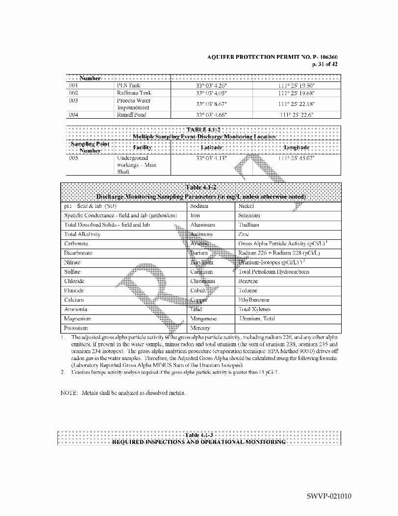
Number
AQUIFER PROTECTION PERMIT NO F- 106360
p.3 of 42
001 PLSTank 33034.26 11125 19.50
002 RaffinateTank 33034.05 11125 19.68
003 Process Water330 03 8.67 1110 25 22.18
Impoundment
004 Runoff Pond 33034.66 1112522.6
Specific Conductance field and lab jimhos/cm Iron Selenium
Total Dissolved Solids field and lab Aluminum Thallium
Total Alkalinity Antimony Zinc
Carbonate Arsenic Gross Alpha Particle Activity pCi/L
Bicarbonate Barium Radium 226 Radium 228 pCi/L
Nitrate Beryllium Uranium-Isotopes pCi/L
Sulfate Cadmium Total Petroleum Hydrocarbons
Chloride Chromium Benzene
Fluoride Cobalt Toluene
Calcium Copper Ethylbenzene
Ammonia Lead Total Xylenes
Magnesium Manganese Uranium Total
Potassium Mercury
The adjusted gross alpha particle activity is the gross alpha particle activity including radium 226 and any other alpha
emitters if present in the water sample minus radon and total uranium the sum of uranium 238 uranium 235 and
uranium 234 isotopes The gross alpha analytical procedure evaporation technique EPA Method 900.0 drives off
radon gas in the water samples Therefore the Adjusted Gross Alpha should be calculated using the following formula
Laboratory Reported Gross Alpha MINUS Sum of the Uranium Isotopes
Uranium Isotope activity analysis required if thegross alpha particle activity
is greater than 15 pCi
NOTE Metals shall be analyzed as dissolved metals
Table 4.1-3
REQUIRED INSPECTIONS AND OPERATIONAL MONITORING
pH field lab SU
SWVP-021010

AQUIFER PROTECTION PERMIT NO F- 106360
p.32 of 42
Operational RequirementsFacility Category Facility Name Inspection Frequency
Process Solution Process Water -Maintain feet of freeboard Daily
Impoundment Impoundment -all discharge and sump pumps
operational
-no substantial erosion
subsidence cracking
-no evidence ofseepage or
other damage to berms
-no visible cracks or damage to
liner
-ftill access to leak detection
system maintained
Lined Non-stormwater Run-off Pond -Maintain feet of freeboard Weekly
Containment Pond -Spil1wty clear of sediment or
obstructions
-no visible cracking or damage
to liner
-no operationa damage to
enclosure wall
-all pumps operational
-backup power supply
operational
-no ponding of spilled material
in pond and sumps-sediment deeper than inch
deep removed from sumps-fluids in sumps maintained at
less than pump-down levels
Storm water control Site-wide stormwater -No substantial erosion or Monthly
structures ditches structural damage-maintained free of sediments
vegetation or obstructions
Groundwater Monitoring Site-wide monitoring Wellhead cap or box locks are Quarterly as sampled
Wells wells observed to be secure
Pumps Site-wide Check hour meters Weekly
Barge Pumps -visual inspection for leaks
Run-Off Transfer Pumps -Lubrication Per manufacturers
Sump Pumps specification
Discharge Pumps -Maintenance and test run Every 1000 to 1200
hours of operation
In-Situ Area Well Field No leakage from pipelines Daily
Injection and Recovery manifolds or well heads
Well Block
In-Situ Area Well Field Initiate subsidence/fissure Quarterly
Injection and Recovery monitoring program
Well Block
SWVP-021011

AQUIFER PROTECTION PERMIT NO F- 106360
p.33 of 42
Facility Name Alert Level Alert Level GPD Monitoring Monitoring Reporting
GPD Method Frequency Frequency
Process Water 2040 16250 Automated Daily Annual
Impoundment
GPD gallons per day per wetted acre
Note The Alert Level AL or Alert Level AL2 shall be exceeded when the amount of leakage pumped from the
sump for the evaporation pond is greater than the applicable quantity above For reporting purposes on the SMRFthe AL is equivalent to the Alert Level and AL2 is equivalent to the DL An exceedance of the DL is not
violation of the permit unless the permittee fails to perform as required under Section 2.6.2.3
Table 41-5
PARAMETERS FOR AMBIENT GROIJND WATER MONITORINGin mg/L unless otherwise noted
Depth to Water Level feet Potassium Nickel
Water Level Elevation feet amsl Sodium Selenium
Temperature field Iron Thallium
pH field ab SU Aluminum Zinc
Specific Conductance field lab Antimony Free Cyanide
jimhos/cm
Total Dissolved Solids field lab Arsenic Gross Alpha Particle Activity pCi/L1
Total Alkalinity Barium Radium 226 pCi/L
Bicarbonate Beryllium Radium 228 pCi/L
Carbonate Cadmium Uranium-IsotopespCi/L2
Hydroxide Chromium Carbon Disulfide
Sulfate Cobalt Benzene
Chloride Copper Toluene
Fluoride Lead Ethylbenzene
Nitrate Nitrite Manganese Total Xylenes
Calcium Mercury Uranium Total
Magnesium Molybdenum
If the oss alpha particle activity is greater than 15 pCi/L then calculate adjusted gross alpha particle activity The
adjusted woss alpha particle activity is the gross alpha particle activity including radium 226 and any other alpha
emitters if present in the water sample minus radon and total uranium the sum of uranium 238 uranium 235 and
uranium 234 isotopes The grass alpha analytical procedure evaporation technique EPA Method 900.0 drives off
radon gas in the water samples Therefore the Adjusted Gross Alpha should be calculated using the following formula
Laboratory Reported Gross Alpha MINUS Sum of the Uranium Isotopes
Uranium Isotope activity analysis required if the gross alpha particle activity is greater than 15 pCi
Table 4.1-4
Leak Collection and Removal System Monitoring
NOTE Metals must be analyzed as dissolved metals
SWVP-021012

AQUIFER PROTECTION PERMIT NO P- 106360
34 of 42
TABLE 4.1-6
QUARTERLY COMPLIAINC MONITORING TABLES LEVEL
ParameterPOC 14- POC Well
POC Well M22-O POC Well M23-UBF
AQL AL AQL AL AQL AL AQL AL
___________________________ mg/I nig/l nig/l mg/l nig/l nig/l mg/l mg/l
epth to v1oni br Monitor Monitor Monitor Monitor 1\loni br Monitor Monitor
irni.nd ater Ii is
Water Level Monitor Monitor Monitor Monitor Monitor Monitor Monitor Monitor
Elevation ft amsl
pH field S.U Monitor Monitor Monitor Monitor Monitor Monitor Monitor Monitor
Specific Conductance Monitor Monitor Monitor Monitor Monitor Muthtor Monitor Monitor
field mhos/cm
Temperature field Monitor Monitor Monitor Monitor Monitor Monitor Monitor Monitor
Fluoride 4.0 3.2 4.0 3.2 4.0 3.2 40 3.2
Magnesium Monitor 23 Monitor 44 Monitor 8.6 Monitor 69
Sulfate Monitor 144 Monitor 126 Monitor 86 Monitor 411
Total dissolved solids Monitor 874 Monitor 1359 Monitor 1094 Monitor 2392
ParameterPOC Well M4-
POC Well M54-O POC Well M2-UBF
AQL AL AQL AL AQL AL
__________________________mg/I mg/I mg/I mg/I mg/I nig/l
epth to Monitor Morn tor Monitor Monitor Monitor Monitor
Groundwater ft
bgs _________ ____________________ __________ _________ ____________
Water Level Monitor Monitor Monitor Monitor Monitor Monitor
Elevation ft amsl__________ _____________________ __________ __________ ____________
pH field S.U Monitor Monitor Monitor Monitor Monitor Monitor
Monitor Monitor Monitor Monitor Monitor MonitorSpecific
Conductance field
nthos/cm
Temperature field Monitor Monitor Monitor Monitor Monitor Monitor
Fluoride Reserved Reserved Reserved Reserved Reserved Reserved
Magnesium Monitor Reserved Monitor Reserved Monitor Reserved
Sulfate Monitor Reserved Monitor Reserved Monitor Reserved
Total dissolved Monitor Reserved Monitor Reserved Monitor Reserved
solids
SWVP-021013

AQUIFER PROTECTION PERMIT NO P- 106360
p.35 of 42
TABLE 4.1-7
SEMI-ANNUAL COMPLIANCE GROUNDWATER MONITORING SEMI-ANNUAL COMPLIANCE
Parameter3 POC Well M14-GL POC Well M15-GU POC Well M22-0 POC Well M23-UBF
AQL AL AQL AL AQL AL AQL AL
___________________________ mg/l mg/l mg/l mg/l mg/l mg/l mg/l mg/l
pH field S.U Monitor Monitor Monitor Monitor Monitor Monitor Monitor Monitor
Specific conductance Monitor Monitor Monitor Monitor Monitor Monitor Monitor Monitor
field_mhos/cm
Temperature field Monitor Monitor Monitor Monitor Monitor Monitor Monitor Monitor
pH lab Monitor Monitor Monitor Monitor Monitor Monitor Monitor Monitor
Bicarbonate Monitor Monitor Monitor Monitor Monitor Monitor Monitor Monitor
Calcium Monitor Monitor Monitor Monitor Monitor Monitor Monitor Monitor
Carbonate Monitor Monitor Monitor Monitor Monitor Monitor Monitor Monitor
Chloride Monitor Monitor Monitor Monitor Monitor Monitor Monitor Monitor
Fluoride 4.0 3.2 4.0 3.2 4.0 3.2 4.0 3.2
Magnesium Monitor 23 Monitor 44 Monitor 8.6 Monitor 69
Nitrate as nitrogen Monitor Monitor Monitor Monitor Monitor Monitor Monitor Monitor
Potassium Monitor Monitor Monitor Monitor Monitor Monitor Monitor Monitor
Sodium Monitor Manitor Monitor Monitor Monitor Monitor Monitor Monitor
Sulfate Monitor 144 Monitor 126 Monitor 86 Monitor 411
Total dissolved solids Monitor 874 Monitor 1359 Monitor 1094 Monitor 2392
Cationlanion balance Monitor Monitor Monitor Monitor Monitor Monitor Monitor Monitor
Aluminum Monitor 0.71 Monitor 4171 Monitor 0.71 Monitor 0.71
Antimony 0.006 0.0048 0.006 0.0048 0.0076 Monitor 0.006 0.0048
Arsenic5 0.05 0.026 QO5 0.026 0.05 0.026 0.05 0.026
Barium 2.0 1.6 20 1.6 2.0 1.6 2.0 1.6
Beryllium 0.004 0.0032 0.0043 0.0032 0.004 0.032 0.004 0.0032
Cadmium 0.005 0.004 0.02 Monitor 0.02 Monitor 0.005 0.004
Chromiumtotal 0.10 0.08 0.10 0.08 0.10 0.08 0.10 0.08
Metals will be analyzed as dissolved metals unless otherwise specified
Nitrate-nitrite as may be determined as the sum of nitrate EPA 352 plus nitrite EPA 354 expressed as
The Alert Level for Arsenic is narrative standard that is applied in order to protect downgradient users and will be revised as necessary in accordance with Section
2.5.7 and Section 3.0 to ensure that the UPL of 10 mg/L is not exceeded at the downgradient edge of the State Mineral Lease Land
SWVP-021014
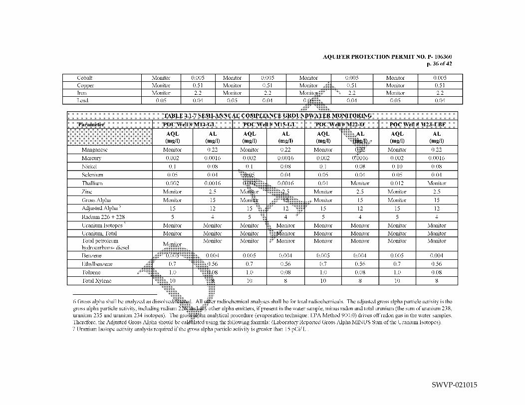
AQUIFER PROTECTION PERMIT NO P- 106360
p.36 of 42
Cobalt Monitor Monitor Monitor Monitor
Copper Monitor 0.51 Monitor 0.51 Monitor 0.51 Monitor 0.51
Iron Monitor 2.2 Monitor 2.2 Monitor 2.2 Monitor 2.2
Lead 0.05 0.04 0.05 0.04 0.04 0.05 0.04
TABLE 4.1-7 SEMI-ANNUAL COMPLIANCE GROUNDWATER MONITORING
Parameter POC Well 14-CL POC Well I-GU POC Well M22-O POC Well M23-UBF
AQL AL AQL AL AQL AL AQL AL
_____________________________mg/i mg/i mg/i mg/i mg/i mg/I mg/i mg/i
ft22 Monitor 0.22Manganese Monitor 0.22 Monitor 0.22 Monitor
Nickel 0.1 0.08 0.1 0.08 0.1 0.08 0.10 0.08
Selenium 0.05 0.04 OQ5 0.04 0.05 0.04 0.05 0.04
Thallium 0.002 0.00 16 QQO2 0.00 16 0.01 Monitor 0.0 12 Monitor
Zinc Monitor 2.5 Monitor 25 Monitor 2.5 Monitor 2.5
Gross Alpha Monitor 15 Monitor 15 Monitor 15 Monitor 15
Adjusted Alpha6 15 12 15 12 15 12 15 12
Radium 226 228
Uranium Isotopes Monitor Monitor Monitor Monitor Monitor Monitor Monitor Monitor
Uranium Total Monitor Monitor Monitor Monitor Monitor Monitor Monitor Monitor
Total petroleum Monitor Monitor Monitor Monitor Monitor Monitor MonitorMonitor
hydrocarbons- diesel
Benzene 0.005 0.004 0.005 0.004 0.005 0.004 0.005 0.004
Ethylbenzene 0.7 0.56 0.7 0.56 0.7 0.56 0.7 0.56
Toluene 1.0 0.08 1.0 0.08 1.0 0.08 1.0 0.08
Total Xylene 10 10 10 10
Gross alpha shall be analyzed as dissolved/filtered All other radiochemical analyses shall be for total radiochemicals The adjusted gross alpha particle activity is the
gross alpha particle activity including radium 226 andany
other alpha emitters if present in the water sample minus radon and total uranium the sum of uranium 238
uranium 235 and uranium 234 isotopes The gro alpha analytical procedure evaporation technique EPA Method 900.0 drives off radon gas in the water samples
Therefore the Adjusted Gross Alpha should be caloulated using the following formula Laboratory Reported Gross Alpha MINUS Sum of the Uranium Isotopes
Uranium Isotope activity analysis required if the gross alpha particle activity is greater than 15 pCi
Mercury 0.002 0.0016 0.002 0.0016 0.002 0.002 0.0016
SWVP-021015

AQUIFER PROTECTION PERMIT NO P- 106360
p.37 of 42
TABLE 4.1-7 SEMI-ANNUAL COMPLIANCE GROUNDWATER MONITORING
Parameter POC Well M54-LBF POC Well M4-O POC Well M2-UBF
AQL AL AQL AL AQL AL
mg/i mg/i mg/i mg/I mg/I mg/i
p11 lick .I Monitor Monitor Monitor Monitor Monitor Monitor
pccific conductance Monitor Monitor Monitor Monitor Monitor Monitor
field_mhos/cm ______________ ____________ ____________ _____________ ____________ _______________
Monitor Monitor
pH lab Monitor Monitor Monitor Monitor Monitor Monitor
Bicarbonate Monitor Monitor Monitor Monitor Monitor Monitor
Calcium Monitor Monitor Monitor Monitor Monitor Monitor
Temperature field Monitor Monitor Monitor Monitor
Carbonate Monitor Monitor Monitor Ivlonitor Monitor Monitor
Chloride Monitor Monitor Monitor IMonitor Monitor Monitor
Fluoride Reserved Reserved Reserved Reserved Reserved Reserved
Magnesium Monitor Reserved Monitor Reserved Monitor Reserved
Nitrate as nitrogen Monitor Monitor Monitor Monitor Monitor Monitor
Potassium Monitor Monitor Monitor Monitor Monitor Monitor
Sodium MonitDr Monitor Monitor Monitor Monitor Monitor
Sulfate Monitor Reserved Monitor Reserved Monitor Reserved
Total dissolved solids Monitor Reserved Monitor Reserved Monitor Reserved
Cationlanion balance Monitor Monitor Monitor Monitor Monitor Monitor
Aluminum Monithr Reserved Monitor Reserved Monitor Reserved
Antimony Reserved Reserved Reserved Reserved Reserved Reserved
Arsenic5 0.05 0.026 0.05 0.026 0.05 0.026
Barium Reserved Reserved Reserved Reserved Reserved Reserved
Beryllium Reserved Reserved Reserved Reserved Reserved Reserved
Cadmium Reserved Reserved Reserved Reserved Reserved Reserved
Chromium total Reserved Reserved Reserved Reserved Reserved Reserved
Cobalt Monitor Reserved Monitor Reserved Monitor Reserved
Copper Monitor Reserved Monitor Reserved Monitor Reserved
Iron Monitor Reserved Monitor Reserved Monitor Reserved
Lead Reserved Reserved Reserved Reserved Reserved Reserved
SWVP-021016

AQUIFER PROTECTION PERMIT NO P- 106360
p.38 of 42
TABLE 4.1-7 SEMI-ANNUAL COMPLIANCE GROUNDWATER MONITORING
Parameter P01 Well M4-LBF P01 Well M4-0 P01 Well M2-LIBF
AQL AL AQL AL AQL AL
mg/i mg/i mg/i mg/i mg/i mg/i
Mwiiaiiese Monitor Reserved Monitor Reserved Monitor Reserved
Mercury Reserved Reserved Reserved Reserved Reserved Reserved
Nickel Reserved Reserved Reserved Reserved Reserved Reserved
Selenium Reserved Reserved Reserved Reserved Reserved Reserved
Thallium Reserved Reserved Reserved Reserved Reserved Reserved
Zinc Monitor Reserved Monitor Reserved Monitor Reserved
Gross Alpha Reserved Reserved Reserved Reserved Reserved Reserved
Adjusted Alpha3 Reserved Reserved Reserved Reserved Reserved Reserved
Radium 226 228 Reserved Reserved Reserved Reserved Reserved Reserved
Uranium Isotopes Monitor Monitor Monitor Monitor Monitor Monitor
Uranium Total Monitor Monitor Monitor Monitor Monitor Monitor
Total petroleum Monitor Monitor Monitor Monitor MonitorMotitor
hydrocarbons- diesel
Benzene 0.005 0.004 0.005 0.004 0.005 0.004
Ethylbenzene 0.7 0.56 0.7 0.56 0.7 0.56
Toluene 1O 0.08 1.0 0.08 1.0 0.08
Total Xylene 10 10 10
SWVP-021017

AQUIFER PROTECTION PERMIT NO F- 106360
p.39 of 42
Recovery Rate Monthly Maximum 300 Flo Meter Monthly
of well fieldaverage gpm
Recovered Daily Recovered I1o Meter Week1
Volume to volume
Injection Injected
Volume Vol uiiie
Inward Daily average -foot Iranstiucer Week1
Hydrologic di krential as
Gradient dai1 erage
Maximum Daily psi/ti Pressure lauge Weekly
Injection
Pressure
Per nionitoring ol designated 4pairs ot ohser\ ation/reco\ en \\ ells TA lift Class IIh
Injection Rate Monthly 24Ogpmof well field
average
Flow Meter Monthly
SWVP-021018

AQUIFER PROTECTION PERMIT NO F- 106360
p.40 of 42
5.0 REFERENCES AND PERTINENT INFORMATION
The terms and conditions set forth in this permit have been developed based upon the information contained in the
following which are on file with the Department
Curis Resources Inc Application for Temporary Individual Aquifer Protection Permit dated March 12 2012
Curis Resources Inc Response to May 2012 Request for Additional Information with Suspension received
May 25 2012
SWVP-021019

AQUIFER PROTECTION PERMIT NO P- 106360
p.41 of 42
6.0 NOTIFICATION PROVISIONS
6.1 Annual Registration Fees
The permittee is notified of the obligation to pay an Annual Registration Fee to ADEQ The Annual Registration
Fee is based upon the amount of daily influent or discharge of pollutants in gallons per day as established by
A.R.S 49-242
6.2 Duty to Comply IA.R.S 49-22 through 49-263
The permittee is notified of the obligation to comply with all conditions ol this permit and all applicable
provisions of Title 49 Chapter Articles and of the Arizona Re ised Statutes Title 18 Chapter
Articles through and Title 18 Chapter 11 Article of the Arizona Administrati Code Any permit non
compliance constitutes violation and is grounds for an enforcement action pursuant to Title 49 Chapter
Article or permit amendment suspension or revocation
6.3 Duty to Provide Information IA.R.S 49-243K2 and 49-243K8IThe permittee shall ftirnish to the Director or an authorized representati\ vs ithin time specified any
information which the Director may request to determine whether cause exists br aniending or terminating this
permit or to determine compliance with this permit The permittee shall also furnish to the irector upon
request copies of records required to be kept by this permit
6.4 Compliance with Aquifer Water Quality Standards IA.R.S 49-243B2 anti 49-243B3The permittee shall not cause or contribute to violation of an aquifer water quality standard at the applicable
point of compliance for the facility Where at the time of issuance of the permit an aquifer already exceeds an
aquifer water quality standard for pollutantS the pernuttee shall not discharge that pollutant so as to ftirther
degrade at the applicable point of compliance lbr the facilit the water quality of any aquifer for that pollutant
6.5 Technical and Financial Capability
IA.R.S 49-243K8 and 49-243N anti A.A.C RI8-9-A202B and R18-9-A203E and
The permittee shall have and maintain the technical and inancial capability necessary toftilly cany out the terms
and conditions of this permit Any bond insurance polk trust lund or other financial assurance mechanism
provided as demonstration of financial capabiIit in the permit application pursuant to A.A.C Ri 8-9-
A203D shall be in effect prior to any discharge authoriied by this permit and shall remain in effect for the
duration ol the perniit
6.6 Reporting of Bankruptcy or Environmental Enforcement IA.A.C R18-9-A207CThe permittee shall notil\ the Director within five days after the occurrence of
any one of the following
The liling of bankruptc the permittee
The entry of any order or udgnient not issued by the Director against the permittee for the enforcement of any
environniental protection statute or rule
6.7 Monitoring anti Records IA.R.S 49-243K8 and A.A.C R18-9-A206The perniittee shall conduct any monitoring activity necessary to assure compliance with this permit with the
applicable \\Liter quaht standards established pursuant to A.R 49-221 and 49-223 and 49-241 through
49-252
6.8 Inspection anti Entry IA.R.S 1-1009 49-203B and 49-243K8In accordance with AR 41-1009 and 49-203B the permittee shall allow the Director or an authorized
representative upon the presentation of credentials and other documents as may be required bylaw to enter and
inspect the facility as reasonably necessary to ensure compliance with Title 49 Chapter Article of the
Arizona Revised Statutes and Title 18 Chapter Articles through of the Arizona Administrative Code and
the terms and conditions of this permit
SWVP-021020

AQUIFER PROTECTION PERMIT NO P- 106360
p.42 of 42
6.9 Duty to Modify IA.R.S 49-243K8 and A.A.C R18-9-A2 11The permittee shall apply for and receive written amendment before deviating from any of the designs or
operational practices specified by this permit
6.10 Permit Action Amendment Transfer Suspension Revocation
IA.R.S 49-201 49-241 through 251 A.A.C R18-9-A211 R18-9-A212 and R18-9-A213J
This permit may be amended transferred renewed or revoked for cause under the rules of the Department
The permittee shall notify the Groundwater Section in writing within 15 days after any change in the owner or
operator of the facility The notification shall state the permit number the name of the facility the date of
property transfer and the name address and phone number where the new owner or operator can be reached
The operator shall advise the new owner or operators of the terms of this permit and the need for permit transfer
in accordance with the rules
7.0 ADDITIONAL PERMIT CONDITIONS
7.1 Other Information IA.R.S 49-243K8JWhere the permittee becomes aware that it failed to submit an rele ant facts in permit application or
submitted incorrect information in permit application or in an report to the Director the permittee shall
promptly submit the correct facts or information
7.2 Severability
IA.R.S 49-201 49-241 through 251 A.A.C R18-9-A2 II I8-9-A2 12 and R18-9-A213J
The provisions of this permit are severable and ifany provision ol this permit or the application of
any
provision of this permit to any circumstance is held invalid the application of such provision to other
circumstances and the remainder of this permit shall not be affected thcreb Ihe filing of request by the
permittee for permit action does not stay or suspend the effectiveness of any existing permit condition
7.3 Permit Transfer
This permit ma not be transferred to any other person except after notice to and approval of the transfer by the
Department No transfer shall be approved until the applicant complies with all transfer requirements as
specified in A.A.U RI -9-A2 121 and
SWVP-021021