jet pump flow control collar - amazon s3 · new slip joint clamp not addressing major contributor...
TRANSCRIPT

Jet PumpFlow Control Collar
Wade MarkhamProduct Manager

Background

Background
3
GE BWR/3-6Core Flow by: Recirculation Pumps and Jet Pumps
Safety Design Basis Assures 2/3 core coverage post
accident LPCI flow path
BWR Recirculation SystemEPRI 2016 Conference - Jet Pump Flow Control Collar

BWR Slip Joint GeometryHold Down Beam
Inlet mixer
Diffuser
Restrainer Bracket
Slip joint
Riser Brace
Riser Pipe
Slip Joint Section View
Mixer Assembly
Jet Pump Assembly
4
Existing Configuration has a Long Annular Flow Path which makes the Slip Joint Unstable
EPRI 2016 Conference - Jet Pump Flow Control Collar

Causes of Flow Induced Vibration
Leakage is the largest contributor to vibration in the jet pump Numerous evaluations have confirmed
EPRI Moss Landing Tests Argonne National Labs
Leakage can be outward or inward based on flow in the jet pump
Vane passing frequencies from recirculation pumps Resonate with natural frequencies of the jet
pump
Turbulent flow from the mixer nozzles
5
Slip Joint FIV is the Major ContributorEPRI 2016 Conference - Jet Pump Flow Control Collar

Specific Issues
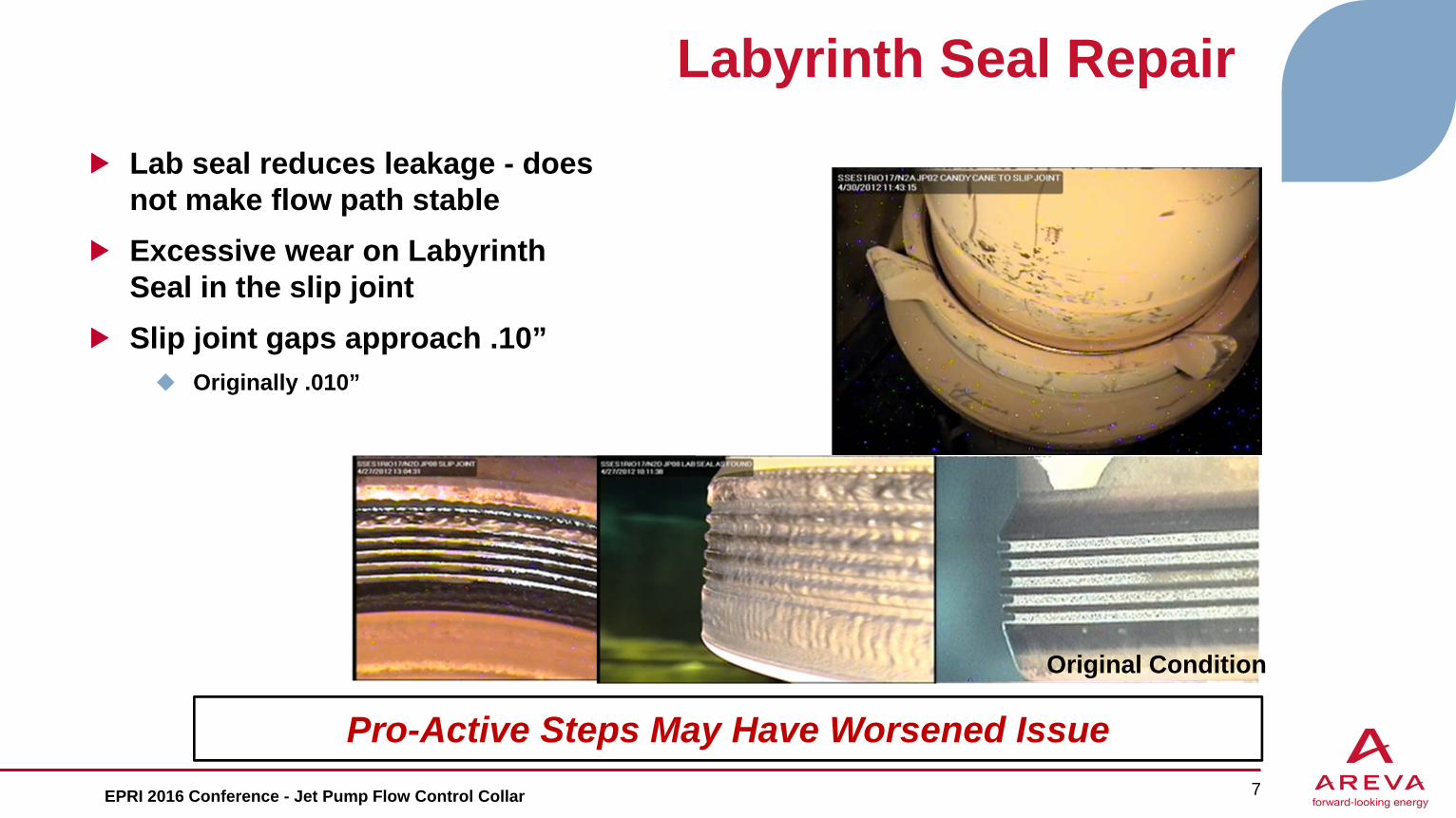
Labyrinth Seal Repair
Pro-Active Steps May Have Worsened Issue 7EPRI 2016 Conference - Jet Pump Flow Control Collar
Lab seal reduces leakage - does not make flow path stableExcessive wear on Labyrinth Seal in the slip jointSlip joint gaps approach .10” Originally .010”
Original Condition

Auxiliary Wedge & Oversize Wedge Repair Methods
Auxiliary wedges damage set screws and mixer After one cycle of operation
Oversize wedge vibration wears guide rod After one cycle of operation
8
Wedges Do Not Address Vibration Source
EPRI 2016 Conference - Jet Pump Flow Control Collar
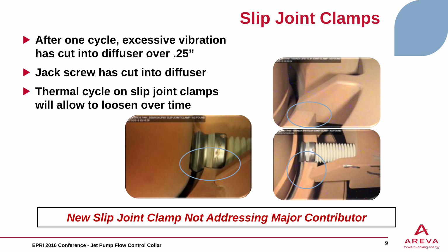
Slip Joint ClampsAfter one cycle, excessive vibration has cut into diffuser over .25”Jack screw has cut into diffuserThermal cycle on slip joint clamps will allow to loosen over time
9
New Slip Joint Clamp Not Addressing Major Contributor
EPRI 2016 Conference - Jet Pump Flow Control Collar
AREVA SolutionDesign Features and Interface Geometry

Design / Performance Requirements
Block as much leakage as possible M-ratio 1.85 design (2.20 actual) (Ratio of output flow vs input) Core Flow 108Mlb/hr 5.4Mlb/hr per jet pump ~10.8k gpm 4.9k gpm from
recirc pump. Core plate DP = ~17 psi Limit leakage below initial design (Initial design gap of slip joint is .010” on
diameter) Operating temperature ~618F
Allow for thermal growth between the mixer and the diffuser .09” of thermal growth expected at slip joint assembly
Avoid any modifications to existing hardwareDesign for remote installationDesign to prevent FME (minimize parts)
11EPRI 2016 Conference - Jet Pump Flow Control Collar

Design RequirementsCodes & Standards Non-code BWRVIP-84 Materials BWRVIP-41 BWR Jet Pump Assembly Inspection and Flaw Evaluation Guidelines BWRVIP-51-A Jet Pump Repair Design Criteria
Loads Repair would be evaluated based on a comparative analysis evaluation If Section III analysis is requested then Jet pump load data will be required.
12
Our Design Seals, Restrains, and Meets BWRVIP Requirements
EPRI 2016 Conference - Jet Pump Flow Control Collar

13
Only Design that Provides Sealing and RestraintEPRI 2016 Conference - Jet Pump Flow Control Collar
Mixer Seal
Hinged joint
Swing clamps to engage diffuser fins
Full contact (clamp does not engage on mixer)
Relief for diffuser fin~34 lbs
Diffuser Seal
Flow Control CollarDesign Features
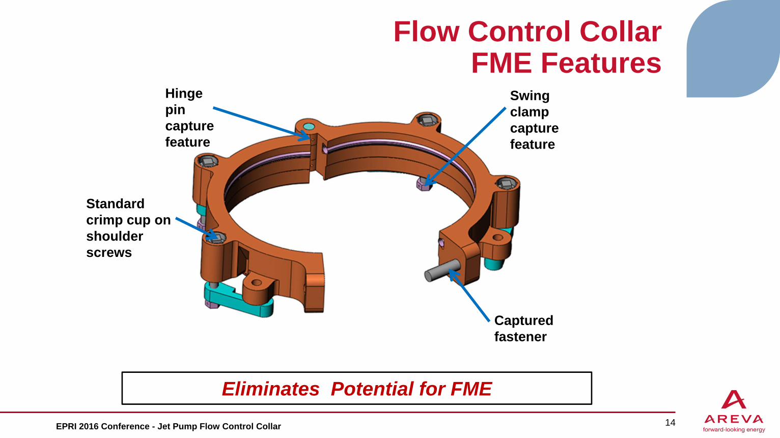
Flow Control CollarFME Features
14
Eliminates Potential for FMEEPRI 2016 Conference - Jet Pump Flow Control Collar
Hinge pin capture feature
Swing clamp capture feature
Captured fastener
Standard crimp cup on shoulder screws

AREVA Flow Control Collar Advantages
The optimal solution that addresses the largest contributor of FIV OEM Aux Wedges and Slip Joint Clamps do not fix the
problem
Minimizes potential leak paths to restrict flowProvides lateral support to tie the mixer to the diffuser while allowing thermal growth Replaces the function of the Slip Joint Clamp
Simple installation, without jet pump disassemblyMinimizes the number of parts in the repair hardwareDoes not require modification to existing hardwareRepair for Life-of-Plant
15
Optimal Solution for Jet Pump Repair
EPRI 2016 Conference - Jet Pump Flow Control Collar
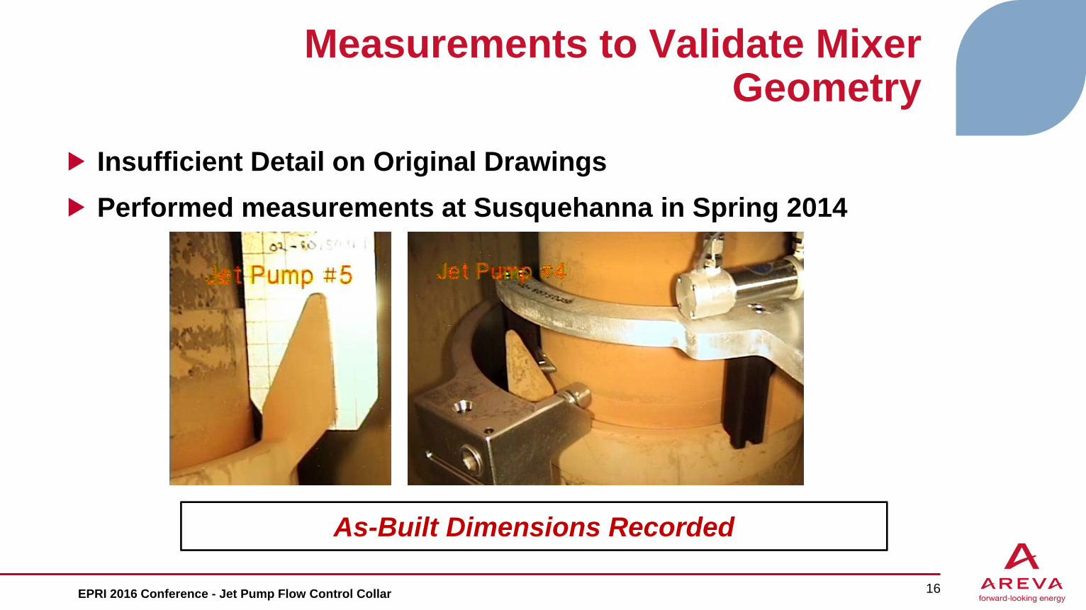
Measurements to Validate Mixer Geometry
Insufficient Detail on Original Drawings Performed measurements at Susquehanna in Spring 2014
16
As-Built Dimensions Recorded
EPRI 2016 Conference - Jet Pump Flow Control Collar
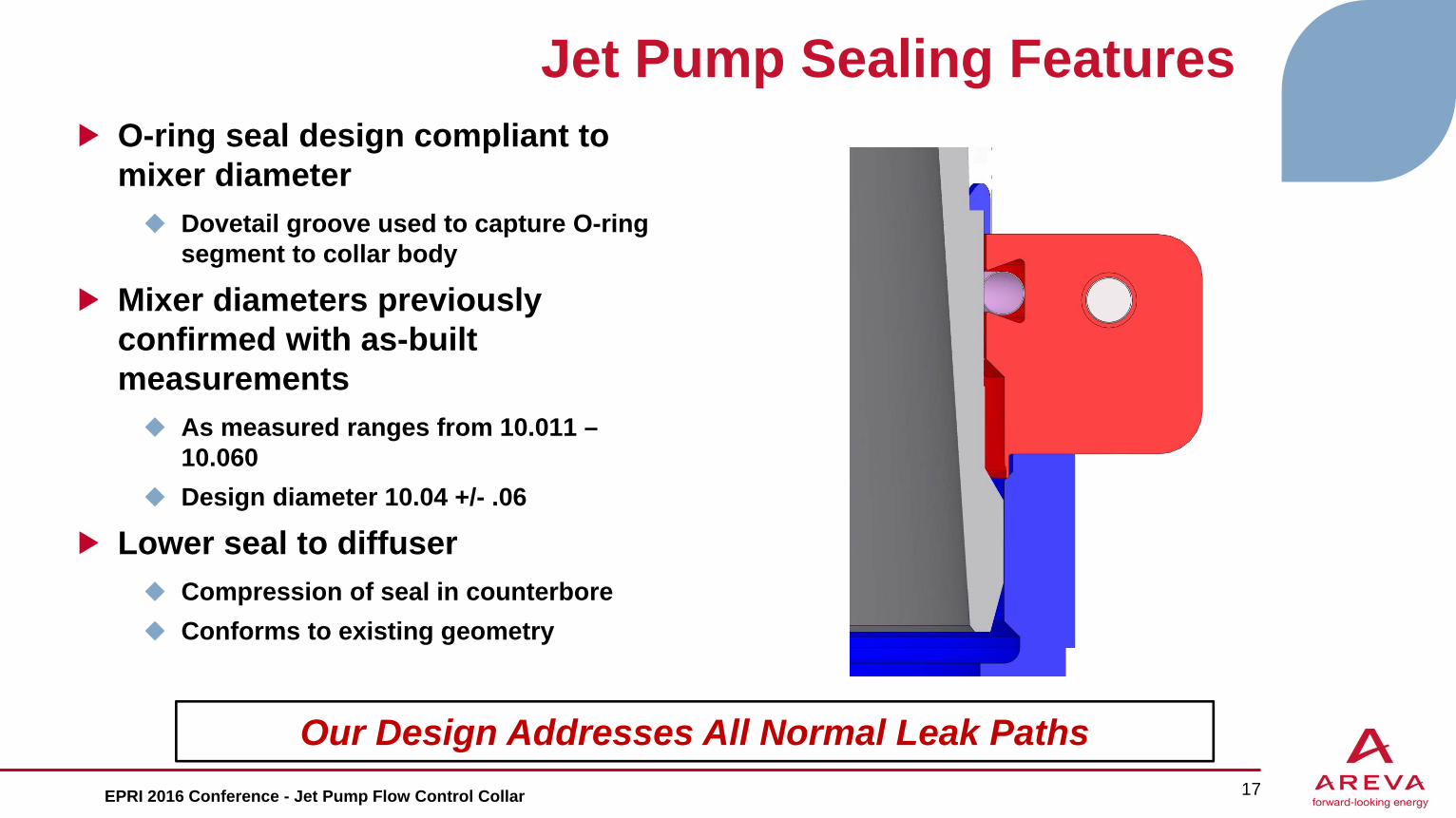
Jet Pump Sealing FeaturesO-ring seal design compliant to mixer diameter Dovetail groove used to capture O-ring
segment to collar body
Mixer diameters previously confirmed with as-built measurements As measured ranges from 10.011 –
10.060 Design diameter 10.04 +/- .06
Lower seal to diffuser Compression of seal in counterbore Conforms to existing geometry
17
Our Design Addresses All Normal Leak PathsEPRI 2016 Conference - Jet Pump Flow Control Collar

Swing ClampsShoulder screw thru collar body Must handle axial and bending loads from
preload as well as axial load from thermal growth
Swing clamps can be locked (tightened) in position when delivered to jet pump Clamp must be positioned before installation
to clear riser pipe and eliminate interference issues
Retainer on swing clamp eliminates potential for FMESwing Clamps threaded in right hand and left hand versions Provides restraint similar to slip joint clamp
18
Innovative Engagement Mechanism
EPRI 2016 Conference - Jet Pump Flow Control Collar
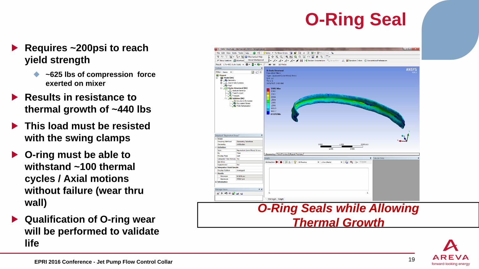
O-Ring SealRequires ~200psi to reach yield strength ~625 lbs of compression force
exerted on mixer
Results in resistance to thermal growth of ~440 lbsThis load must be resisted with the swing clampsO-ring must be able to withstand ~100 thermal cycles / Axial motions without failure (wear thru wall)Qualification of O-ring wear will be performed to validate life
19
O-Ring Seals while Allowing Thermal Growth
EPRI 2016 Conference - Jet Pump Flow Control Collar

Analysis of the Repair
Analysis will be performed to determine a relative motion between the mixer and diffuserHolding force vs. time/temperature will be calculated, to assess primary qualification and to do fatigue calculation Loads on the mixer and diffuser will be evaluated (expected to be negligible)
20EPRI 2016 Conference - Jet Pump Flow Control Collar

AREVA Teams with Structural Integrity Associates, Inc.
Comprehensive repair solutions to ensure operational excellence in the U.S. boiling water reactor (BWR) fleet: Onsite and offsite engineering analysis Repair, and replacement of BWR vessel internals
Repair and replacement capabilities, including but not limited to the following components: Jet Pumps Feedwater Spargers Core Spray Piping Core Shroud Top Guide Core Plate Reactor Vessel Steam Dryer Steam Separator
Benefits: AREVA has extensive experience in BWR internals
repair and replacement SI has a highly respected and proven reputation as a
quality provider of reliable BWR engineering analysis One integrated source for cost-effective BWR
analysis and repair solutions Service providers that know your teams and
understand your cultureBest of the Best for Engineering &
Installation ServicesEPRI 2016 Conference - Jet Pump Flow Control Collar 21

Preliminary Testing Results
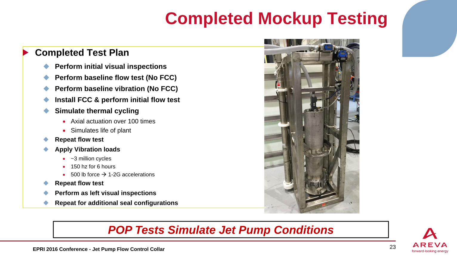
Completed Mockup Testing
Completed Test Plan Perform initial visual inspections Perform baseline flow test (No FCC) Perform baseline vibration (No FCC) Install FCC & perform initial flow test Simulate thermal cycling
Axial actuation over 100 times Simulates life of plant
Repeat flow test Apply Vibration loads
~3 million cycles 150 hz for 6 hours 500 lb force 1-2G accelerations
Repeat flow test Perform as left visual inspections Repeat for additional seal configurations
23
POP Tests Simulate Jet Pump ConditionsEPRI 2016 Conference - Jet Pump Flow Control Collar
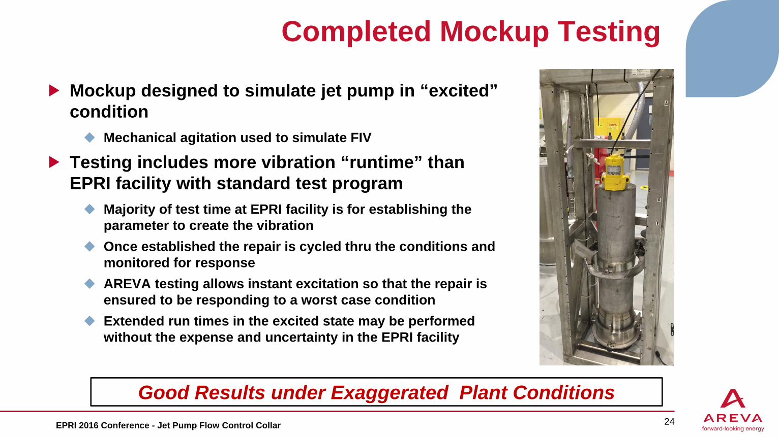
Completed Mockup Testing
Mockup designed to simulate jet pump in “excited” condition Mechanical agitation used to simulate FIV
Testing includes more vibration “runtime” than EPRI facility with standard test program Majority of test time at EPRI facility is for establishing the
parameter to create the vibration Once established the repair is cycled thru the conditions and
monitored for response AREVA testing allows instant excitation so that the repair is
ensured to be responding to a worst case condition Extended run times in the excited state may be performed
without the expense and uncertainty in the EPRI facility
24
Good Results under Exaggerated Plant ConditionsEPRI 2016 Conference - Jet Pump Flow Control Collar
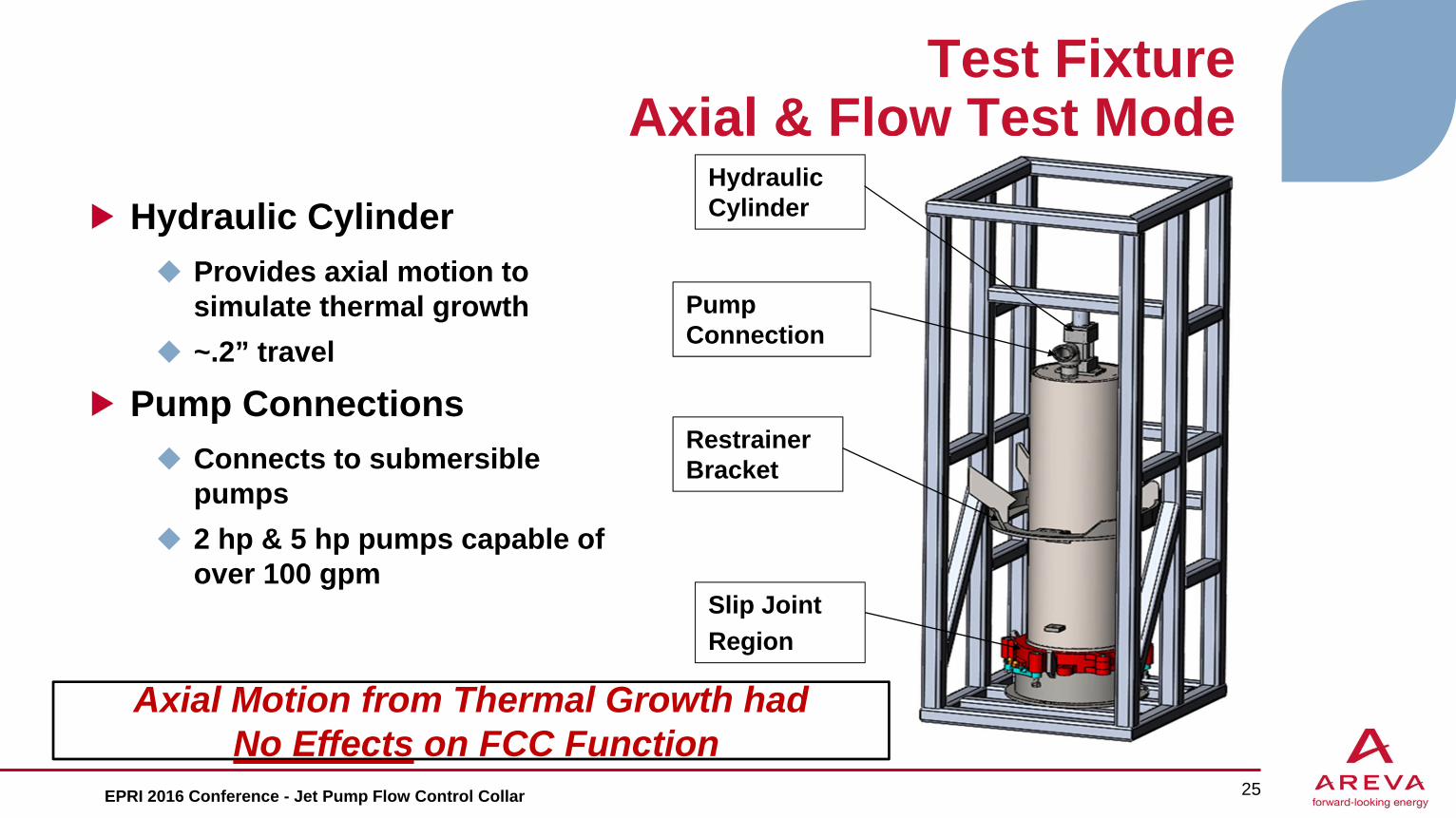
Test FixtureAxial & Flow Test Mode
Hydraulic Cylinder Provides axial motion to
simulate thermal growth ~.2” travel
Pump Connections Connects to submersible
pumps 2 hp & 5 hp pumps capable of
over 100 gpm
25
Hydraulic Cylinder
Pump Connection
Slip JointRegion
Restrainer Bracket
Axial Motion from Thermal Growth hadNo Effects on FCC Function
EPRI 2016 Conference - Jet Pump Flow Control Collar
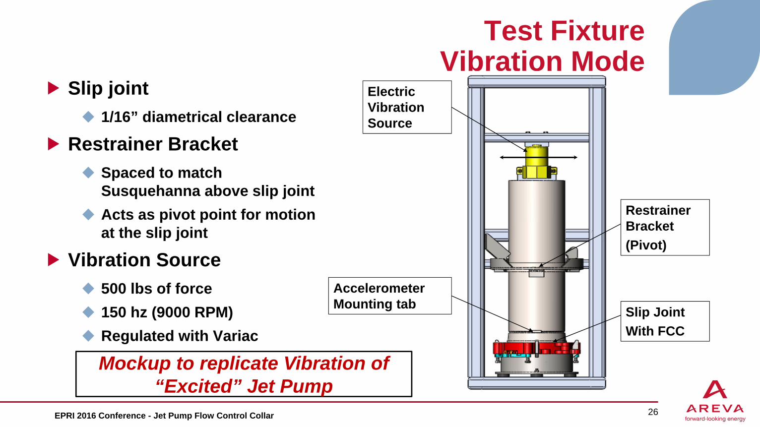
Test FixtureVibration Mode
Slip joint 1/16” diametrical clearance
Restrainer Bracket Spaced to match
Susquehanna above slip joint Acts as pivot point for motion
at the slip joint
Vibration Source 500 lbs of force 150 hz (9000 RPM) Regulated with Variac ~ 2g Acceleration
26
Electric Vibration Source
Restrainer Bracket(Pivot)
Slip JointWith FCC
Accelerometer Mounting tab
Mockup to replicate Vibration of “Excited” Jet Pump
EPRI 2016 Conference - Jet Pump Flow Control Collar

Seal Materials
Three seals evaluated for the test Stainless Steel O-Ring
Materials readily available Need to improve fabrication method
Grafoil seal Already used in plant for many sealing applications Rated for 2030 psi Rated for 896 F
27
AREVA has confirmed two options for seal materialsEPRI 2016 Conference - Jet Pump Flow Control Collar

Vibration ResultsVideo of Vibration
28
With SS O-Ring
Baseline
With Grafoil
Dramatic Decrease in Vibration
EPRI 2016 Conference - Jet Pump Flow Control Collar
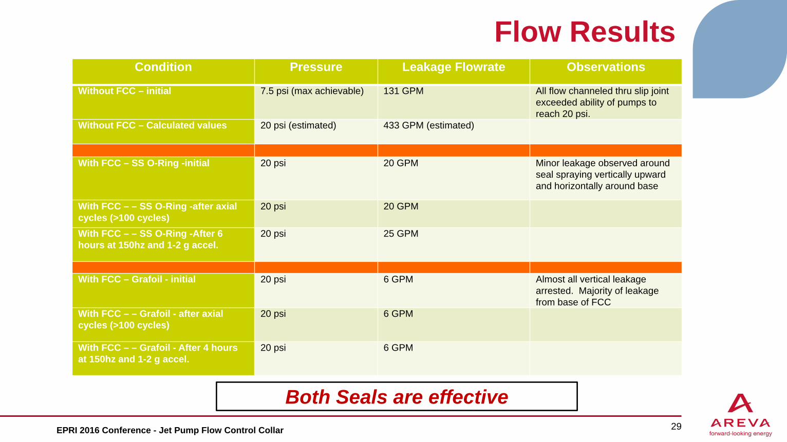
Flow ResultsCondition Pressure Leakage Flowrate Observations
Without FCC – initial 7.5 psi (max achievable) 131 GPM All flow channeled thru slip joint exceeded ability of pumps to reach 20 psi.
Without FCC – Calculated values 20 psi (estimated) 433 GPM (estimated)
With FCC – SS O-Ring -initial 20 psi 20 GPM Minor leakage observed around seal spraying vertically upward and horizontally around base
With FCC – – SS O-Ring -after axial cycles (>100 cycles)
20 psi 20 GPM
With FCC – – SS O-Ring -After 6 hours at 150hz and 1-2 g accel.
20 psi 25 GPM
With FCC – Grafoil - initial 20 psi 6 GPM Almost all vertical leakage arrested. Majority of leakage from base of FCC
With FCC – – Grafoil - after axial cycles (>100 cycles)
20 psi 6 GPM
With FCC – – Grafoil - After 4 hours at 150hz and 1-2 g accel.
20 psi 6 GPM
29
Both Seals are effectiveEPRI 2016 Conference - Jet Pump Flow Control Collar

Wear Results
No wear observedDiscoloration noted Removed with cleaning
30
Before Testing After Testing
Before Testing After Testing
No Wear Observed
EPRI 2016 Conference - Jet Pump Flow Control Collar
Discoloration -No Wear
No Wear

Additional Proposed Testing
Final seal design qualification testing Perform extensive vibration testing on final seal design Validate longevity of seal design
Extended run time vibration testing
Crimp cup qualification testing Confirm breakaway torque for removal of crimped fasteners Confirm crimp engagement parameters
EPRI 2016 Conference - Jet Pump Flow Control Collar 31
Planning Success without EPRI Testing

Conclusions and Observations
The Flow Control Collar reduces leakage and resists vibrationThe SS O-ring could be improved by: Annealing the O-ring Better forming to avoid ovalization Thinner wall thickness Silver coating similar to head o-rings
Grafoil packing performed very well Verifying life of grafoil seal material under vibration loading with manufacturer
32
Testing Confirms Flow Control Collar Reduces Leakage and Resists Vibration
EPRI 2016 Conference - Jet Pump Flow Control Collar
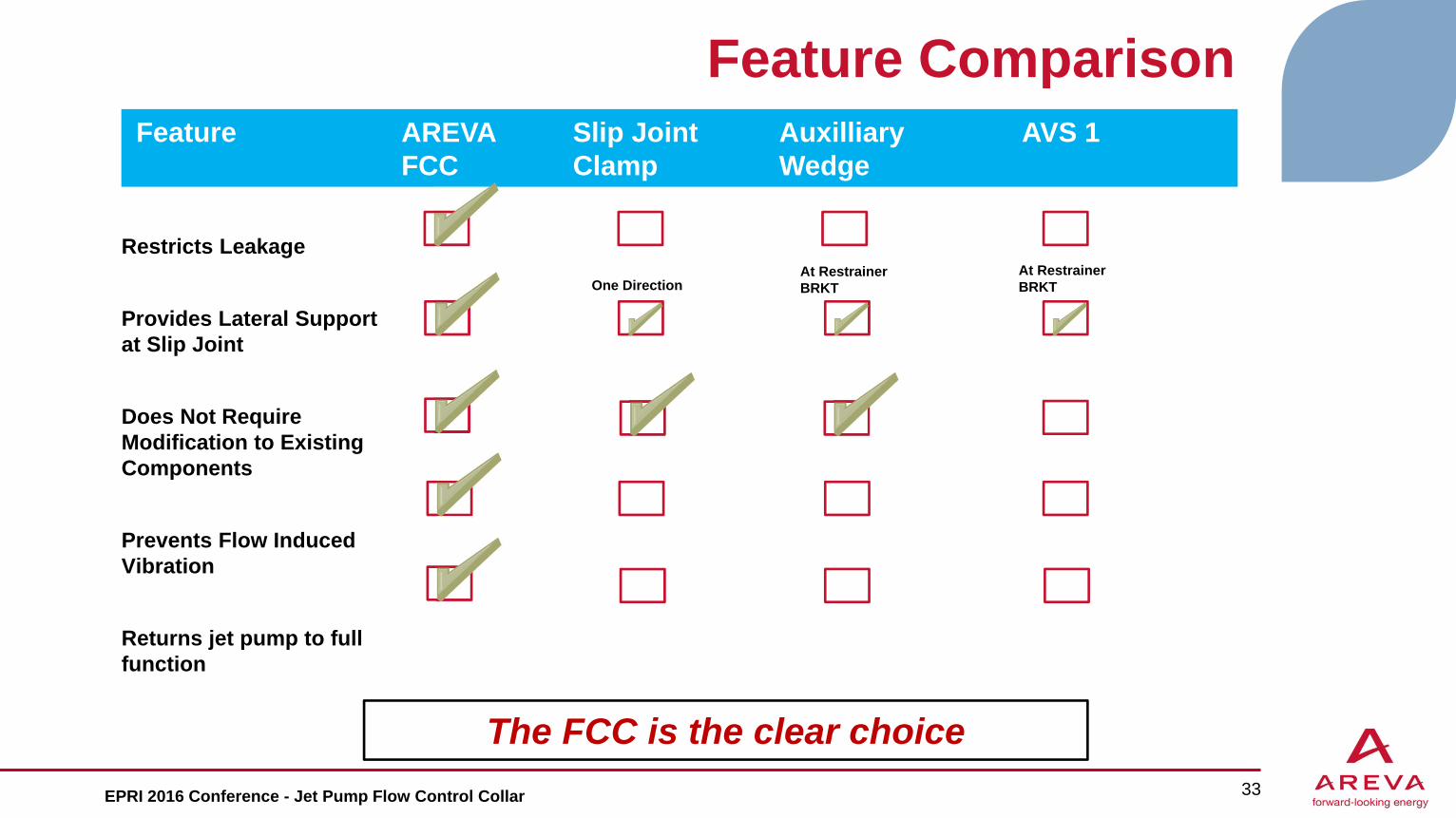
Feature Comparison
EPRI 2016 Conference - Jet Pump Flow Control Collar 33
Feature AREVA FCC
Slip Joint Clamp
AuxilliaryWedge
AVS 1
The FCC is the clear choice
Restricts Leakage
Provides Lateral Support at Slip Joint
Does Not Require Modification to Existing Components
Prevents Flow Induced Vibration
Returns jet pump to full function
One DirectionAt Restrainer BRKT
At Restrainer BRKT

Installation
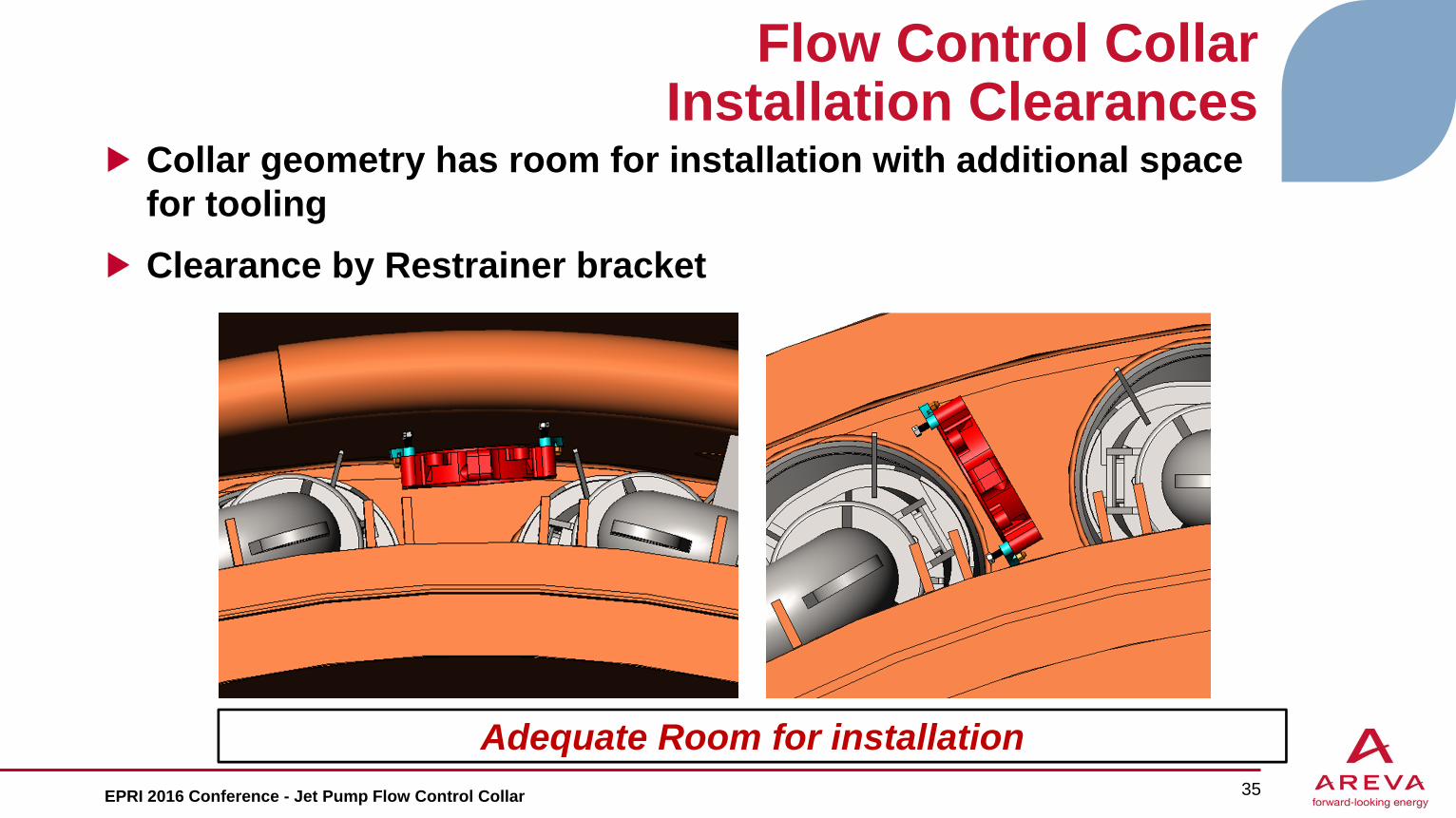
Flow Control CollarInstallation Clearances
Collar geometry has room for installation with additional space for toolingClearance by Restrainer bracket
35
Adequate Room for installationEPRI 2016 Conference - Jet Pump Flow Control Collar

Flow Control CollarInstallation Clearances
Collar will be opened and engage mixer assembly under restrainer bracket
36EPRI 2016 Conference - Jet Pump Flow Control Collar
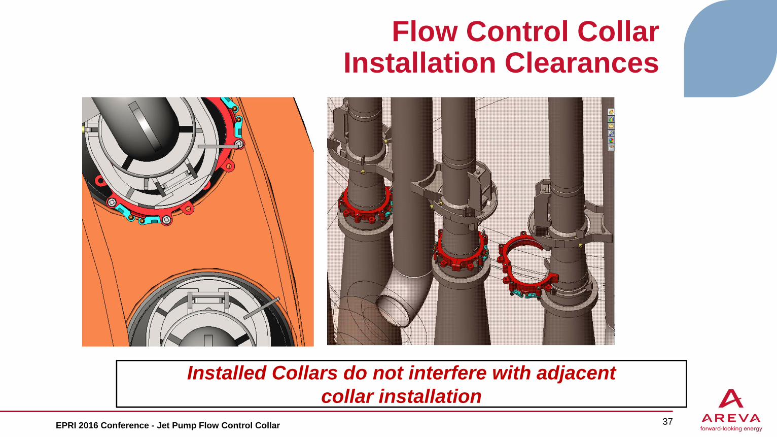
Flow Control CollarInstallation Clearances
37
Installed Collars do not interfere with adjacent collar installation
EPRI 2016 Conference - Jet Pump Flow Control Collar

Why AREVA
Most effective solution to Seal and Restrain the jet pump slip joint Minimizes potential leak paths to restrict flow Provides lateral support to tie the mixer to the
diffuser while allowing thermal growth Replaces the function of the Slip Joint Clamp
Simple installation, without jet pump disassemblyDoes not require modification to existing hardwareRepair for Life-of-PlantAREVA is ready to work with Utilities to resolve your jet pump issues
38EPRI 2016 Conference - Jet Pump Flow Control Collar