jffs3 design issues - memory technology device
TRANSCRIPT

Abstract
JFFS2, the Journalling Flash File System version 2, is widely used in the embeddedsystems world. It was designed for relatively small flash chips and has serious problemswhen it is used on large flash devices. Unfortunately, these scalability problems are deepinside the design of the file system, and cannot be solved without full redesign.
This document describes JFFS3 – a new flash file system which is designed to bescalable.
Contents
1 JFFS2 overview 1
2 JFFS3 Requirements 2
3 Introduction to JFFS3 33.1 Indexing problem . . . . . . . . . . . . . . . . . . . . . . . . . . . . . . . 33.2 Wandering trees . . . . . . . . . . . . . . . . . . . . . . . . . . . . . . . . 43.3 B+-trees . . . . . . . . . . . . . . . . . . . . . . . . . . . . . . . . . . . . 53.4 Indexing in JFFS3 . . . . . . . . . . . . . . . . . . . . . . . . . . . . . . 63.5 The Journal . . . . . . . . . . . . . . . . . . . . . . . . . . . . . . . . . . 83.6 The superblock . . . . . . . . . . . . . . . . . . . . . . . . . . . . . . . . 10
4 The superblock 104.1 The superblock management algorithm . . . . . . . . . . . . . . . . . . . 104.2 The length of the chain . . . . . . . . . . . . . . . . . . . . . . . . . . . . 144.3 The superblock search . . . . . . . . . . . . . . . . . . . . . . . . . . . . 16
5 Issues/ideas/to be done 16
6 Definitions 18
7 Symbols 19
8 Abbreviations 20
9 Credits 20
10 References 20
1 JFFS2 overview
JFFS2, the Journalling Flash File System version 2 [1] is widely used in the embeddedsystems world. JFFS2 was originally designed for small NOR flashes (< 32MB) and thefirst device with JFFS2 file system was a small bar-code scanner. Later, when NANDflashes became widely used, NAND support was added to JFFS2. The first NAND flasheswere also small enough, but grew in size very quickly and are currently much larger then32MB (e.g., Samsung produces 2GB NAND flashes [4]).
JFFS2 has log-structured design, which basically means, that the whole file systemmay be regarded as one large log. Any file system modification (i.e., file change, directorycreation, changing file’s attributes, etc) is appended to the log. The log is the only datastructure on the flash media. Modifications are encapsulated into small data structurescalled nodes.
So, JFFS2 is roughly a log, the log consists of nodes, each node contains a file systemmodification. And this is basically all JFFS2 file system is. It is very simple from thephysical layout’s standpoint. For more information about the design of JFFS2 and aboutthe log-structured design, look at [1], [2], and [3].
It is not the goal of this chapter to delve into details of JFFS2 but still but it isstill wanted to provide enough information to make it clear why JFFS2 has scalabilityproblems and why JFFS3 is needed. To keep this chapter simple, terms index or indexinginformation are used.
The index is a crucial part of any file system as it is used to keep track of everythingthat is stored in the file system. For example, the index may help to quickly locate theaddresses of physical blocks which correspond to the specified file at the specified offset,or it helps to quickly find all the directory entries in a specified directory and so on.
For example, in case of ext2, the inode table, the bitmap and the set of direct, indirect,doubly indirect and triply indirect pointers may be considered the index. In case of theFAT file system, the File Allocation Table may be considered as the index, etc.
In traditional file systems the index is usually kept and maintained on the media, butunfortunately, this is not the case for JFFS2. In JFFS2, the index is maintained in RAM,not on the flash media. And this is the root of all the JFFS2 scalability problems.
Of course, having the index in RAM JFFS2 achieves extremely high file systemthroughput, just because it does not need to update the index on flash after somethinghas been changed in the file system. And this works very well for relatively small flashes,for which JFFS2 was originally designed. But as soon as one tries to use JFFS2 on largeflashes (starting from about 128MB), many problems come up.
At first, it is obvious, that JFFS2 needs to build the index in RAM when it mountsthe file system. For this reason, it needs to scan the whole partition in order to locate allthe nodes which are present there. So, the larger is JFFS2 partition, the more nodes ithas, the longer it takes to mount it.
The second, it is evidently that the index consumes some RAM. And the larger is theJFFS2 file system, the more nodes it has, the more memory is consumed.
To put it differently, if S is the size of the JFFS3 flash partition 1,
• JFFS2 mount time scales as O(S) (linearly);
• JFFS2 memory consumption scales as O(S) (linearly).
1Note, all the symbols used in this document are referred in the section 7
1
So, it may be stood that JFFS2 does not scale. But in spite of the scalability problems,JFFS2 has many advantages:
• very economical flash usage – data usually take as much flash space as it actuallyneed, without wasting a lot space as in case of traditional file systems for blockdevices;
• admitting of ”on-flight” compression which allows to fit a big deal of data to theflash; note, there are few file systems which support compression;
• very file system write throughput (no need to update any on-flash indexing infor-mation as it simply does not exist there);
• unclean reboot robustness;
• good enough wear-leveling.
It is also worth noting here, that there is a patch which is usually referred to as the”summary patch”, that was implemented by Ferenc Havasi and was recently committedto the JFFS2 CVS. This patch speed up the JFFS2 mount greatly, especially in case ofNAND flashes. What the patch basically does is that it puts a small ”summary” nodeat the end of each flash erasable block. This node, roughly speaking, contains the copyof headers of all the nodes in this eraseblocks. So, when JFFS2 mounts the file system, itneeds to glance to the end of each eraseblock and read the summary node. This results inthat JFFS2 only needs to read one or few NAND pages from the end of each eraseblock.Instead, when there is no summary, JFFS2 reads almost all the NAND pages of theeraseblock, because the node headers are spread more or less evenly over the eraseblock.
Although the patch helps a lot, it is still a not scalable solution and it only relaxes thecoefficient of the JFFS2 mount time liner dependency. Let alone that it does not lessenthe memory consumption.
2 JFFS3 Requirements
The following are the main user level requirements JFFS3 have to meet.
R01 JFFS3 memory consumption must not depend on the size of the JFFS3 partition,the number of inodes in the file system, size of files, directories, and the like. Ofcourse, JFFS3 must be able to use the advantage of the available RAM, but only fordifferent kinds of caches which may be freed any time in case of memory pressure.
R02 JFFS3 have to provide very fast file system mount without the need to scan thewhole flash partition.
R03 JFFS3 have to provide good flash wear-levelling.
R04 JFFS3 must guarantee that unclean reboots cannot cause any file system corruption.
R05 JFFS3 must provide good enough performance.
R06 Unlike JFFS2, JFFS3 must implement write-behind caching for better performance.
2
R07 JFFS3 must gracefully deal with different kinds of data corruptions, flash bits flip-ping, bad blocks which may appear dynamically, etc.
R08 In case of serious corruptions it should be possible to reconstruct the any data whichwere not damaged by means external tools like ckfs.jffs3.
R09 All the JFFS3 characteristics ought to vary not faster then log(S), where S is thesize of the JFFS3 partition. JFFS2-like linear dependencies are not acceptable.
R10 JFFS3 must support extended attributes.
R11 JFFS3 must support Access Control Lists feature (ACLs).
R12 JFFS3 have to support on-flight compression.
3 Introduction to JFFS3
The main idea how to fix in JFFS2 to make it scalable is to move the index from RAM toflash. Unfortunately, this requires complete JFFS2 redesign and re-implementation andthe design of JFFS3 is largely different to the design of JFFS2. This section discussesthe base JFFS3 design ideas without any detailed description.
3.1 Indexing problem
There is a large difference between block devices and flash devices in how they allow toupdate the contents of a sector. Block devices admit of so-called ”in-place updates”, i.e.the update may be written straight to the sector. Flash devices do not allow this unlessthe whole eraseblock has been erased before.
Obviously, it is unacceptable to erase the whole eraseblock each time a sector isupdated. Instead, so-called ”out-of-place updates” technique is usually used. This simplymeans, that no attempts to update the sector in-place is made, but instead, the update iswritten to some other sector and the contents of the previous sector is afterwords regardedas garbage.
This ”out-of-place writes” property of flash devices assumes that JFFS3 also haslog-structured design as in JFFS3 any update is written out-of-place. And it seems thatthis is natural for any flash file system to have log-structured design.
It is interesting to notice that in log-structured file systems for block devices (likethe one described in [2]) not any update is ”out-of-place”. There are always somefixed-position sectors present. These sectors usually refer the file system index admittingof quick file system mount and they are updated in-place in these file systems.
But flash devices have limited number of erase cycles for each eraseblock and it isimpossible to guaranty good wear-levelling if some eraseblocks are reserved for simi-lar purposes. So, it is important that in JFFS3 there are no in-place updates as goodwear-levelling is one of the main requirements to JFFS3 (see section 2).
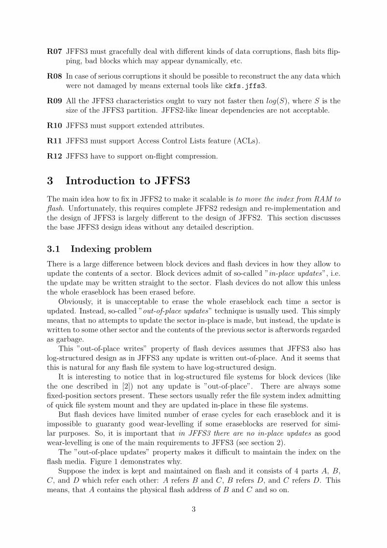
The ”out-of-place updates” property makes it difficult to maintain the index on theflash media. Figure 1 demonstrates why.
Suppose the index is kept and maintained on flash and it consists of 4 parts A, B,C, and D which refer each other: A refers B and C, B refers D, and C refers D. Thismeans, that A contains the physical flash address of B and C and so on.
3
A
B
C
D
Flash
A B C D D1
D1
Figure 1: JFFS3 indexing problem example.
Suppose D should be updated. Since it is updated out-of-place, the newer version D1
is written to some other place. But there are B and C which still refer D and they oughtto be updated as well. And when they are updated out-of-place, A still refers the old Band C, and so on. Thus, it is not that trivial to store indexing information on flash.
3.2 Wandering trees
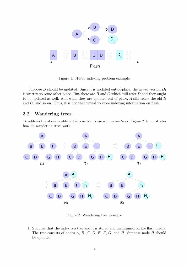
To address the above problem it is possible to use wandering trees. Figure 2 demonstrateshow do wandering trees work.
A
B E F
C D G H
(1)
A
B E F
C D G H
(2)
H1
A
B E F
C D G H
(3)
H1
F1
A
B E F
C D G H
(4)
H1
F1
A1
B E
C D G H
(5)
H1
F1
A1
Figure 2: Wandering tree example.
1. Suppose that the index is a tree and it is stored and maintained on the flash media.The tree consists of nodes A, B, C, D, E, F , G, and H. Suppose node H shouldbe updated.
4
2. At first, the updated version H1 is written. Obviously, F still refers H.
3. Now the corresponding links in node F are changed and node F1 is written to flash.F1 refers H1. But as F1 is also written out-of-place, A still refers the old node F .
4. Finally, the new root node A1 is written ant it refers F1.
5. Nodes A, F , H are now treated as garbage and the updated tree contains nodesA1, B, C, D, E, F1, G, and H1.
So, wandering trees is the base idea of how the indexing information is going to bemaintained on the flash media in JFFS3. And it stands to reason that any tree maybe called ”wandering tree” if any update in the tree requires updating parent nodes upto the root. For example, it makes sense to talk about wandering Red-Black trees orwandering B+-trees and so forth.
3.3 B+-trees
JFFS3 uses B+-trees and this subsection makes a short introduction to B+-trees. Thereis a plenty of books where one may find more information.
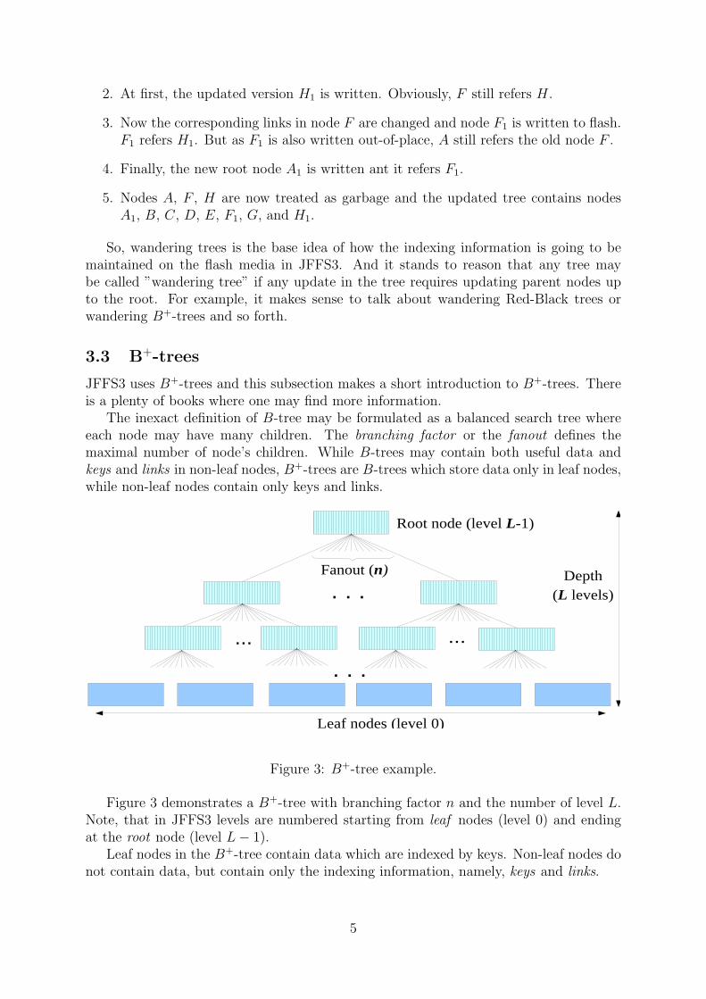
The inexact definition of B-tree may be formulated as a balanced search tree whereeach node may have many children. The branching factor or the fanout defines themaximal number of node’s children. While B-trees may contain both useful data andkeys and links in non-leaf nodes, B+-trees are B-trees which store data only in leaf nodes,while non-leaf nodes contain only keys and links.
. . .
... ...
. . .
Fanout (n)
Leaf nodes (level 0)
Depth(L levels)
Root node (level L-1)
Figure 3: B+-tree example.
Figure 3 demonstrates a B+-tree with branching factor n and the number of level L.Note, that in JFFS3 levels are numbered starting from leaf nodes (level 0) and endingat the root node (level L − 1).
Leaf nodes in the B+-tree contain data which are indexed by keys. Non-leaf nodes donot contain data, but contain only the indexing information, namely, keys and links.
5

...
Key 1
Link 2
Key 2
Link 3
Key 3
Key n-1Link n
Link 1
< Key 1
> Key 1 and < Key 2
> Key n. . .
Link n-1
Figure 4: The structure of a non-leaf node in B+-tree.
Figure 4 depicts the structure of a non-leaf node. There are n links and n − 1 keysin the node. Links may point to either leaf nodes or other non-leaf nodes. In the formercase, the leaf node will contain data which corresponds to the key which follows the link.In the latter case, the pointed non-leaf node (and the whole subtree with the root in thisnon-leaf node) will contain more keys in range (Key 1, Key 2].
Keys are sorted in the ascending order in non-leaf nodes, so it is not that difficultto lookup data corresponding to any key. Furthermore, the tree is balanced, so the thenumber of lookup steps does not depend on the key.
When objects are inserted or removed from the tree, re-balancing may be needed. Thetree is re-balanced by means of splitting nodes or merging them and there is a simpleenough algorithm exists. Please, refer to Donald Knuth’s books for more informationabout re-balancing B+-trees.
B+-trees are widely used when working with block devices (e.g., hard drives). Indeed,these devices have a fixed input/output unit size (usually referred to as a sector) and itis natural to use B+-trees with node size multiple to the size of the sector in order tostore information on such devices.
3.4 Indexing in JFFS3
The way how JFFS3 stores and indexes the file system is similar to the approach usedby the Reiser4 file system (see [5]). All the file system objects (inodes, files, directoryentries, extended attributes, etc) are kept in one large B+-tree. Effectively, the wholeJFFS3 file system may be regarded as one large B+-tree. This tree is further referred tojust as ”the tree”.
Every object which is stored in the tree has a key, and the object is found in the treeby this key. To make it clearer what object keys are, the following is an example of howthey may look like:
• file data key: {inode number, offset};
• directory entry key: {parent directory inode number, direntry name hash};
• extended attribute key: {target inode number, xattr name hash} and the like.
The following are terms which are used in JFFS3 to refer nodes of different levels inthe tree:
• nodes of level 0 are leaf nodes ;
6

• nodes of level 1 are twig nodes ;
• nodes which are not the root, not leaf, and not twig are branch nodes ;
• no-leaf nodes (i.e., the root, branch and twig) are indexing nodes.
Note, the same terminology (except indexing nodes) is used in the Reiser4 file sys-tem [5].
Non-leaf nodes are called ”indexing nodes” because they contain only indexing infor-mation, nothing else. No file system data is kept in the indexing nodes. Indexing nodeshave fixed size which is equivalent to the flash sector size.
It is important to note that somewhat unusual terminology is used in this document.The smallest input/output unit of the flash chip is called sector. Since JFFS3 mainlyorients to NAND flashes, the sector is mostly the NAND page and is either 512 bytesor 2 Kilobytes. For other flash types the sector may be different. If flash’s minimalinput/output unit is very small (like one bit in case of NOR flash) there should be a layerwhich emulates larger sectors (say, 512 bytes).
In opposite to indexing nodes, leaf nodes have flexible size, just like nodes in JFFS2.So, roughly speaking, JFFS3 file system may be considered as JFFS2 file system (leafnodes) plus indexing information (figure 5).
. . .
... ...
. . .
Leaf nodes have flexible size and the leaf level reminds JFFS2
Indexing nodes have fixed sizeand index leaf nodes which
contain FS objects
Figure 5: The JFFS3 tree.
Similarly to JFFS2, leaf nodes consist of header and data. The header describes thenode data and contains information like the key of the node, the length, and the like.Node data contains some file system data, for example directory entry, file’s contents,etc.
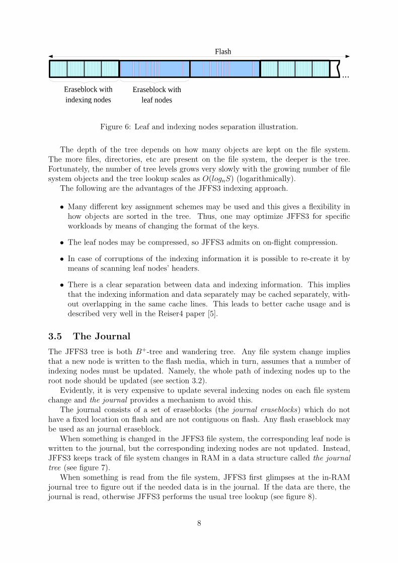
Leaf and indexing nodes are physically separated, which means that there are erase-blocks with only indexing nodes and with only leaf nodes. But of course, this does notmean that the whole flash partition is divided on two parts, this only means that theindexing and leaf nodes are not in one eraseblock. Figure 6 illustrates this.
Eraseblocks which contain only indexing nodes are called indexing eraseblocks andthose with leaf nodes are called leaf eraseblocks.
7
...
Eraseblock with indexing nodes
Eraseblock with leaf nodes
Flash
Figure 6: Leaf and indexing nodes separation illustration.
The depth of the tree depends on how many objects are kept on the file system.The more files, directories, etc are present on the file system, the deeper is the tree.Fortunately, the number of tree levels grows very slowly with the growing number of filesystem objects and the tree lookup scales as O(lognS) (logarithmically).
The following are the advantages of the JFFS3 indexing approach.
• Many different key assignment schemes may be used and this gives a flexibility inhow objects are sorted in the tree. Thus, one may optimize JFFS3 for specificworkloads by means of changing the format of the keys.
• The leaf nodes may be compressed, so JFFS3 admits on on-flight compression.
• In case of corruptions of the indexing information it is possible to re-create it bymeans of scanning leaf nodes’ headers.
• There is a clear separation between data and indexing information. This impliesthat the indexing information and data separately may be cached separately, with-out overlapping in the same cache lines. This leads to better cache usage and isdescribed very well in the Reiser4 paper [5].
3.5 The Journal
The JFFS3 tree is both B+-tree and wandering tree. Any file system change impliesthat a new node is written to the flash media, which in turn, assumes that a number ofindexing nodes must be updated. Namely, the whole path of indexing nodes up to theroot node should be updated (see section 3.2).
Evidently, it is very expensive to update several indexing nodes on each file systemchange and the journal provides a mechanism to avoid this.
The journal consists of a set of eraseblocks (the journal eraseblocks) which do nothave a fixed location on flash and are not contiguous on flash. Any flash eraseblock maybe used as an journal eraseblock.
When something is changed in the JFFS3 file system, the corresponding leaf node iswritten to the journal, but the corresponding indexing nodes are not updated. Instead,JFFS3 keeps track of file system changes in RAM in a data structure called the journaltree (see figure 7).
When something is read from the file system, JFFS3 first glimpses at the in-RAMjournal tree to figure out if the needed data is in the journal. If the data are there, thejournal is read, otherwise JFFS3 performs the usual tree lookup (see figure 8).
8

...
Journal eraseblock Leaf eraseblock Indexing eraseblock
The journal tree (in RAM)
Describes changes which were not yet checkpointed
Figure 7: The JFFS3 journal.
Lookup the journal treeand find out if the
journal contains therequested information.
Lookup the tree
Found
Read the journal
Not found
Read request
JFFS3
Figure 8: The read request processing in JFFS3.
The journal is checkpointed when it is full or in some other appropriate for JFFS3time. This means, that the indexing nodes corresponding to the journal changes areupdated and written to the flash. The checkpointed journal eraseblocks are then treatedas leaf eraseblocks and new journal eraseblocks are picked by JFFS3 using the commonJFFS3 wear-levelling algorithm.
The journal makes it possible to postpone indexing information updates to later andpotentially more appropriate time. It also allows to merge many indexing nodes updatesand lessen the amount of flash write operations.
When JFFS3 file system is being mounted, the journal should be read, ”replayed”and the journal tree should be built. So, the larger is the journal the longer it may taketo mount JFFS3. From the other hand, the larger is the journal, the more writes maybe deferred and the better performance may be achieved. By the other words, there is atrade-off between the mount time and the performance and one may vary them by meansof changing the size of the journal.
9
3.6 The superblock
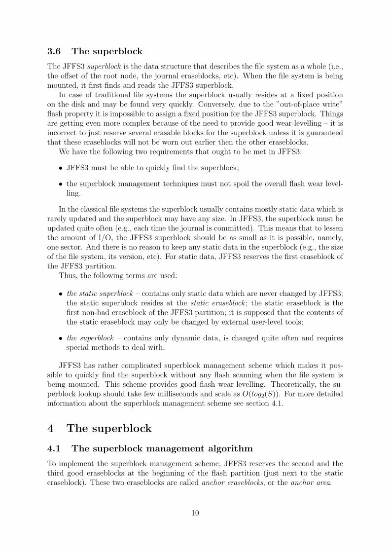
The JFFS3 superblock is the data structure that describes the file system as a whole (i.e.,the offset of the root node, the journal eraseblocks, etc). When the file system is beingmounted, it first finds and reads the JFFS3 superblock.
In case of traditional file systems the superblock usually resides at a fixed positionon the disk and may be found very quickly. Conversely, due to the ”out-of-place write”flash property it is impossible to assign a fixed position for the JFFS3 superblock. Thingsare getting even more complex because of the need to provide good wear-levelling – it isincorrect to just reserve several erasable blocks for the superblock unless it is guaranteedthat these eraseblocks will not be worn out earlier then the other eraseblocks.
We have the following two requirements that ought to be met in JFFS3:
• JFFS3 must be able to quickly find the superblock;
• the superblock management techniques must not spoil the overall flash wear level-ling.
In the classical file systems the superblock usually contains mostly static data which israrely updated and the superblock may have any size. In JFFS3, the superblock must beupdated quite often (e.g., each time the journal is committed). This means that to lessenthe amount of I/O, the JFFS3 superblock should be as small as it is possible, namely,one sector. And there is no reason to keep any static data in the superblock (e.g., the sizeof the file system, its version, etc). For static data, JFFS3 reserves the first eraseblock ofthe JFFS3 partition.
Thus, the following terms are used:
• the static superblock – contains only static data which are never changed by JFFS3;the static superblock resides at the static eraseblock ; the static eraseblock is thefirst non-bad eraseblock of the JFFS3 partition; it is supposed that the contents ofthe static eraseblock may only be changed by external user-level tools;
• the superblock – contains only dynamic data, is changed quite often and requiresspecial methods to deal with.
JFFS3 has rather complicated superblock management scheme which makes it pos-sible to quickly find the superblock without any flash scanning when the file system isbeing mounted. This scheme provides good flash wear-levelling. Theoretically, the su-perblock lookup should take few milliseconds and scale as O(log2(S)). For more detailedinformation about the superblock management scheme see section 4.1.
4 The superblock
4.1 The superblock management algorithm
To implement the superblock management scheme, JFFS3 reserves the second and thethird good eraseblocks at the beginning of the flash partition (just next to the staticeraseblock). These two eraseblocks are called anchor eraseblocks, or the anchor area.
10
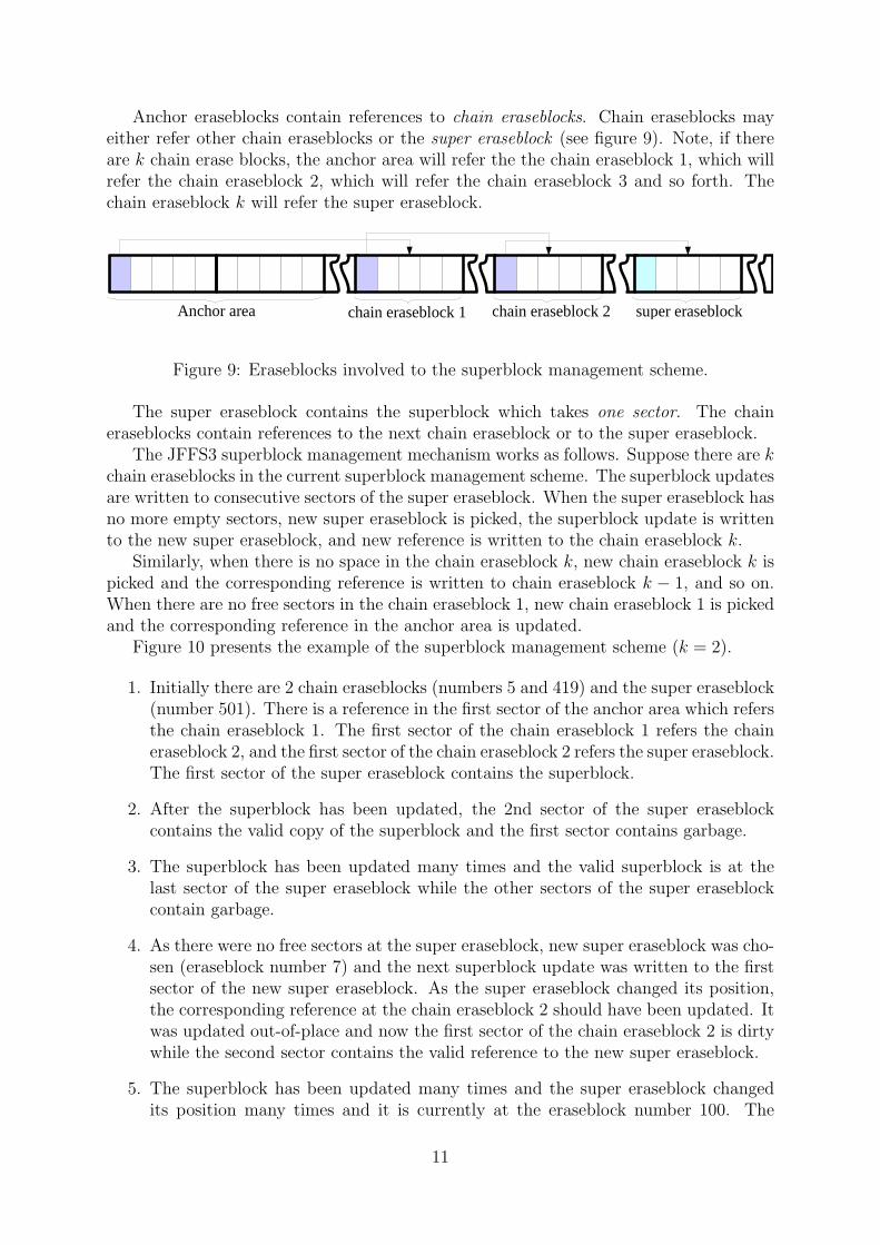
Anchor eraseblocks contain references to chain eraseblocks. Chain eraseblocks mayeither refer other chain eraseblocks or the super eraseblock (see figure 9). Note, if thereare k chain erase blocks, the anchor area will refer the the chain eraseblock 1, which willrefer the chain eraseblock 2, which will refer the chain eraseblock 3 and so forth. Thechain eraseblock k will refer the super eraseblock.
Anchor area chain eraseblock 1 chain eraseblock 2 super eraseblock
Figure 9: Eraseblocks involved to the superblock management scheme.
The super eraseblock contains the superblock which takes one sector. The chaineraseblocks contain references to the next chain eraseblock or to the super eraseblock.
The JFFS3 superblock management mechanism works as follows. Suppose there are kchain eraseblocks in the current superblock management scheme. The superblock updatesare written to consecutive sectors of the super eraseblock. When the super eraseblock hasno more empty sectors, new super eraseblock is picked, the superblock update is writtento the new super eraseblock, and new reference is written to the chain eraseblock k.
Similarly, when there is no space in the chain eraseblock k, new chain eraseblock k ispicked and the corresponding reference is written to chain eraseblock k − 1, and so on.When there are no free sectors in the chain eraseblock 1, new chain eraseblock 1 is pickedand the corresponding reference in the anchor area is updated.
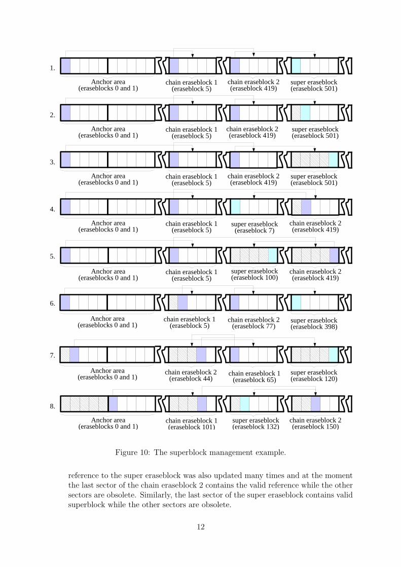
Figure 10 presents the example of the superblock management scheme (k = 2).
1. Initially there are 2 chain eraseblocks (numbers 5 and 419) and the super eraseblock(number 501). There is a reference in the first sector of the anchor area which refersthe chain eraseblock 1. The first sector of the chain eraseblock 1 refers the chaineraseblock 2, and the first sector of the chain eraseblock 2 refers the super eraseblock.The first sector of the super eraseblock contains the superblock.
2. After the superblock has been updated, the 2nd sector of the super eraseblockcontains the valid copy of the superblock and the first sector contains garbage.
3. The superblock has been updated many times and the valid superblock is at thelast sector of the super eraseblock while the other sectors of the super eraseblockcontain garbage.
4. As there were no free sectors at the super eraseblock, new super eraseblock was cho-sen (eraseblock number 7) and the next superblock update was written to the firstsector of the new super eraseblock. As the super eraseblock changed its position,the corresponding reference at the chain eraseblock 2 should have been updated. Itwas updated out-of-place and now the first sector of the chain eraseblock 2 is dirtywhile the second sector contains the valid reference to the new super eraseblock.
5. The superblock has been updated many times and the super eraseblock changedits position many times and it is currently at the eraseblock number 100. The
11
Anchor area (eraseblocks 0 and 1)
chain eraseblock 1 (eraseblock 5)
chain eraseblock 2(eraseblock 419)
super eraseblock (eraseblock 501)
Anchor area (eraseblocks 0 and 1)
chain eraseblock 1 (eraseblock 5)
chain eraseblock 2(eraseblock 419)
super eraseblock (eraseblock 501)
Anchor area (eraseblocks 0 and 1)
chain eraseblock 1 (eraseblock 5)
chain eraseblock 2(eraseblock 419)
super eraseblock (eraseblock 501)
Anchor area (eraseblocks 0 and 1)
chain eraseblock 1 (eraseblock 5)
chain eraseblock 2(eraseblock 419)
super eraseblock (eraseblock 7)
Anchor area (eraseblocks 0 and 1)
chain eraseblock 1 (eraseblock 5)
chain eraseblock 2(eraseblock 419)
super eraseblock (eraseblock 100)
Anchor area (eraseblocks 0 and 1)
chain eraseblock 1 (eraseblock 5)
chain eraseblock 2(eraseblock 77)
super eraseblock (eraseblock 398)
Anchor area (eraseblocks 0 and 1) chain eraseblock 1
(eraseblock 65)chain eraseblock 2
(eraseblock 44)super eraseblock (eraseblock 120)
Anchor area (eraseblocks 0 and 1)
chain eraseblock 1 (eraseblock 101)
chain eraseblock 2(eraseblock 150)
super eraseblock (eraseblock 132)
1.
2.
3.
4.
5.
6.
7.
8.
Figure 10: The superblock management example.
reference to the super eraseblock was also updated many times and at the momentthe last sector of the chain eraseblock 2 contains the valid reference while the othersectors are obsolete. Similarly, the last sector of the super eraseblock contains validsuperblock while the other sectors are obsolete.
12
6. When the next superblock update came, there were no free sectors at the supereraseblock and new super eraseblock was picked (eraseblock number 398) and thevalid copy of the superblock is currently at the first sector of the eraseblock num-ber 398, Also, there were no free sectors at the chain eraseblock 2 and new chaineraseblock 2 was found (eraseblock number 77), so the first sector of the erase-block 77 contains the valid reference to the super eraseblock. Since the chain erase-block 2 changed its position, the corresponding reference at the chain eraseblock 1was updated and at the moment the second sector of the chain eraseblock 1 containsthe valid reference to the chain eraseblock 2 while the first sector is dirty.
7. And analogously, after many superblock updates, the chain eraseblock 1 was up-dated many times and when it became full it changed its position. Sure, the chaineraseblock 2 and the super eraseblock changed their positions many times as well.So, at the moment, the chain eraseblock 1 is at the eraseblock number 65, thechain eraseblock 2 is at the eraseblock 44 and the super eraseblock is at the erase-block 120. When the chain eraseblock 1 changed its position, the correspondingreference at the anchor area was updated and currently the second sector of theanchor eraseblock 1 contains the valid reference to the chain eraseblock 1 while thefirs sector is dirty.
8. And even more superblock updates happened. The anchor area was updated manytimes. When there were no free sectors at the anchor eraseblock 1, the anchoreraseblock 2 was used. So, at the moment, the valid reference to the chain erase-block 1 is at the first sector of the anchor eraseblock 2. From now on, the firstanchor eraseblock may be erased and may be used again when the second anchoreraseblock becomes full.
The following are important notes about the JFFS3 superblock management.
• The superblock takes one sector so the super eraseblock may be updated at mostN times (N is the number of sectors in the eraseblock).
• In case of NAND flash, the sector is the real minimal physical input/output unit, soonly N updates are possible in the anchor eraseblock and in the chain eraseblocks.But if the real input/output unit is smaller then the sector (i.e., if JFFS3 works ontop of NOR flash) the advantage of this may be used and more references may bepacked into one anchor or chain eraseblock.
• When JFFS3 picks new chain/super eraseblock, the common JFFS3 wear-levellingscheme is utilized.
• Anchor area has 2 eraseblocks in order to ensure the tolerance to unclean reboots –one anchor eraseblock may be safely erased while the other is being used.
• When a new reference is written to anchor/chain eraseblocks, the previous referencebecomes dirty and on mount JFFS3 should find the valid reference. To facilitatethis, each reference has its version number. Each subsequent reference has higherversion then the previous. Hence, JFFS3 may use the binary search algorithm toquickly find the valid reference.
13
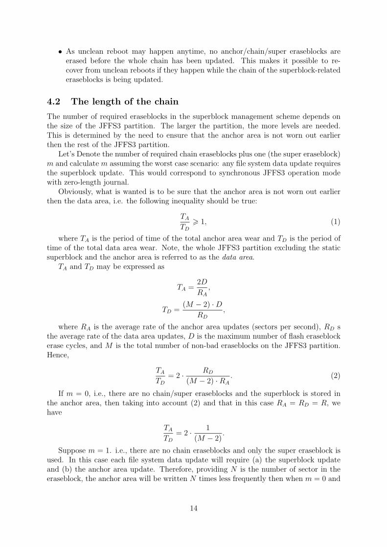
• As unclean reboot may happen anytime, no anchor/chain/super eraseblocks areerased before the whole chain has been updated. This makes it possible to re-cover from unclean reboots if they happen while the chain of the superblock-relatederaseblocks is being updated.
4.2 The length of the chain
The number of required eraseblocks in the superblock management scheme depends onthe size of the JFFS3 partition. The larger the partition, the more levels are needed.This is determined by the need to ensure that the anchor area is not worn out earlierthen the rest of the JFFS3 partition.
Let’s Denote the number of required chain eraseblocks plus one (the super eraseblock)m and calculate m assuming the worst case scenario: any file system data update requiresthe superblock update. This would correspond to synchronous JFFS3 operation modewith zero-length journal.
Obviously, what is wanted is to be sure that the anchor area is not worn out earlierthen the data area, i.e. the following inequality should be true:
TA
TD
> 1, (1)
where TA is the period of time of the total anchor area wear and TD is the period oftime of the total data area wear. Note, the whole JFFS3 partition excluding the staticsuperblock and the anchor area is referred to as the data area.
TA and TD may be expressed as
TA =2D
RA
,
TD =(M − 2) ·D
RD
,
where RA is the average rate of the anchor area updates (sectors per second), RD sthe average rate of the data area updates, D is the maximum number of flash eraseblockerase cycles, and M is the total number of non-bad eraseblocks on the JFFS3 partition.Hence,
TA
TD
= 2 · RD
(M − 2) ·RA
. (2)
If m = 0, i.e., there are no chain/super eraseblocks and the superblock is stored inthe anchor area, then taking into account (2) and that in this case RA = RD = R, wehave
TA
TD
= 2 · 1
(M − 2).
Suppose m = 1. i.e., there are no chain eraseblocks and only the super eraseblock isused. In this case each file system data update will require (a) the superblock updateand (b) the anchor area update. Therefore, providing N is the number of sector in theeraseblock, the anchor area will be written N times less frequently then when m = 0 and
14

the data area will be written 2 times more frequently then when m = 0. This means,that RA = R/N and RD = 2R and from (2) we have
TA
TD
= 2 · 2N
M − 2.
When m = 2, i.e. the chain eraseblock 1 and the super eraseblock are used, theanchor area will be written N2 times less frequently, while the data area will be written2 + 1/N times more frequently then when m = 0 (one superblock update on each filesystem update and one chain eraseblock 1 update per N superblock updates). Therefore,RA = R/N2 and RD = (2 + 1/N) ·R and from (2) we have
TA
TD
= 2 · 2N2 + N
M − 2.
For m = 3, analogously,
TA
TD
= 2 · 2N3 + N2 + N
M − 2,
and for m = 0, 1, 2, . . .
TA
TD
= 2 · 2Nm + Nm−1 + . . . + N
M − 2.
Consequently, from (1) we have the following inequality:
2 · 2Nm + Nm−1 + . . . + N
M − 2> 1,
or neglecting the minor components,
4Nm
M> 1,
or
m > logNM
4. (3)
Thus, form (3) it is obvious that the JFFS3 superblock management scheme scaleslogarithmically.
Table 1 shows the value of m for different types of existing NAND flashes.
Type Size Sect. size M N mToshiba TC58DVM92A1FT 64MB 16KB 4096 32 2Toshiba TH58NVG1S3AFT05 512MB 128KB 4096 64 2ST Micro NAND08G-B 1GB 128KB 8192 64 2Samsung K9K1G08X0B 2GB 128KB 16384 64 2
Table 1: The length of the JFFS3 superblock management chain for different types ofexisting NAND flashes.
Note, providing that N = 64, m = 3 is enough to guarantee acceptable anchor areawear leveling for up to 128GB flash, m = 4 – for up to 8TB flash (the inequality 3).
15

4.3 The superblock search
To find the superblock during mount, JFFS3 finds the valid reference in the anchoreraseblocks, then finds the valid reference in chain erase blocks 1, 2, . . ., m − 1, andfinally finds the valid superblock in the super eraseblock. Since JFFS3 assigns versions tosectors of anchor/chain/super eraseblock and the versions are increased by one on everyupdate, the binary search algorithm may be used to find the valid sector.
The valid reference in the anchor area may be found after log2(2N) + 2 steps (onestep involves one sector read operation), the reference in chain/super eraseblocks – afterlog2(N) + 2 steps. Thus, to find the superblock, JFFS3 must read
S = 2(m + 1) + log2(2N) + m · log2(N)
sectors.Table 2 contains the approximate superblock search time for different existing NAND
flashes. 2
Type Size N m Sect. read S SB findToshiba TC58DVM92A1FT 64MB 32 2 ∼50µs 22 ∼1.1msST Micro NAND08G-B 1GB 64 2 ∼130µs 25 ∼3.3msSamsung K9K1G08X0B 2GB 64 2 ∼70µs 25 ∼1.6ms
Table 2: The superblock search time for different existing NAND flashes.
For larger flash chips which would utilize the superblock management scheme withn = 3 (no such flashes exist at the moment), the superblock search time would be about4.3ms, providing the flash characteristics are the same as ST Micro’s (see table 2).
Note, the calculated SB search time doesn’t contain the ECC/CRC checking overheadas well as any other CPU overhead.
5 Issues/ideas/to be done
This section is a temporary list of issues which should be solved, ideas which should bethought and analyzed more or things which were thought about but are not yet describedin this document.
The following is the list of things which should be thought about more.
1. Quota support. Will quota be supported? How will it look like – lust generic linuxquota or something better?
2. Transactions:transaction open()/do many fs modifications()/transaction close() seman-tics? Reiser4 pretends to support this via special sys reiser4() syscall. Wouldbe nice.
2the calculated superblock search time doesn’t contain the ECC/CRC checking overhead as well asany other CPU overhead.
16
3. Does it make sense to ”compress” keys. For example, if there are many consecutivekeys with the same prefix, we may write this prefix only once. Will there be someproblems when these compressed keys are changed and cannot be compressed anylonger? Will this need some horrid tree and re-balancing? The idea of ”extents” issimilar.
4. How can one select the compression mode on the per-inode basis? Xattrs with somereserved name?
5. ACLs... Will they be implemented via xattrs or it will be something tricker/better?
The following is the list of topics which should be highlighted in this document aswell.
1. Garbage collection.
2. Caching, write-behind cache.
3. An assumed flash model and the model of interactions between JFFS3 and the flashI/O subsystem.
4. How the track of eraseblocks will be kept? Space accounting, good/bad, erasecount?
5. The wear-levelling algorithms.
6. The format of keys.
7. Branch nodes’ links are sector numbers, twig nodes’ links are absolute flash offsets.So, the length of twig and branch keys are different and branches have greaterfanout.
8. Different optimizations may be achieved by means of changing the format of keys.So, JFFS3 should be flexible in this respect and have a mechanism to change/selectthe formats of keys.
The following is the list of ideas which were thought about but are not yet in thedocument.
1. If the compression is disabled for an inode, then its nodes are (PAGE SIZE + headersize) in size, i.e., they do not fit into integer number of flash sectors. For thesenodes we may keep the header in the OOB area. In this case we should not mixcompressed nodes and uncompressed nodes in one eraseblock.
2. For large files which are mostly read-only, we may fit more then one page of datein one node. This will mace compression better. When the file is read, all theuncompressed pages are propagated to the page cache, like in the zisofs file system.
3. If there are few date in the superblock, we may keep this data in the root node. Inthis case the root will have smaller fanout then branches.
The ”to do” list.
1. Review the ”definitions section”. Add more terms there, e.g., checkpointing, quota,branching factor, indexing, leaf, journal, anchor, chain, super eraseblocks.
17

6 Definitions
1. Access Control List, ACL – a modern mechanism to control accesses to files,see [6] for more details.
2. Anchor eraseblock, anchor area – the second and the third good eraseblocks ofthe JFFS3 partition which are reserved for the superblock management.
3. Branch node – any node that is not leaf, not twig and not root.
4. Chain eraseblock – an eraseblock containing references to other chain eraseblocksor to the super eraseblock. Chain eraseblocks facilitate quick SB searching and arepart of the JFFS3 superblock management scheme (see section 4.1).
5. Directory entry – basically associates a name with an inode number. Directoriesmay be considered as a list of directory entries.
6. Erasable block, eraseblock – the minimal erasable unit of the flash chip fromthe JFFS3’s viewpoint.
7. Data area – the whole JFFS3 partition excluding the static superblock and theanchor eraseblocks.
8. Dirty sector – a sector with data which is not valid any longer, recycled by GarbageCollector.
9. Garbage Collector, – a part of any Flash File System which is responsible forrecycling dirty space and producing free eraseblocks.
10. Indexing information, index – data structures which do not contain files, direc-tories, extended attributes or whatever is seen by user, but instead, keep track ofthis data. For example, indexing information allows to quickly find all the directoryentries for any specified directory. I case of the FAT file system, the File Alloca-tion Table is the index, in case of ext2 the inode table, the bitmap and the set ofdirect, indirect, doubly indirect and triply indirect pointers may be considered asthe index. In JFFS3, the indexing nodes may be referred to as the index.
11. Journal – contains all the recent JFFS3 changes. Its purpose is to accumulate abunch of JFFS3 file system changes and and to postpone updating the index. Seesection 3.5 for more information.
12. Journal eraseblock – an eraseblock containing the journal data.
13. Journal tree – an in-memory tree referring Journal nodes which were not com-mitted so far. For more information see section 3.5.
14. Leaf node – any node from the leaf level of the tree (level 0). Leaf nodes containonly data and do not further refer other nodes. For more information see section3.4.
15. Node – a pile of the tree (the tree consists of nodes). There are different types ofnodes in JFFS3. For more information see section 3.4.
18
16. Out-of-place updates, out-of-place writes – a sort of data update when theupdated version is not written to the same physical position, but instead, writtento some other place and the previous contents is treated as garbage afterwords.Opposite to in-place updates.
17. Sector – the smallest writable unit of the flash chip, from the JFFS3’s viewpoint.E.e. the NAND page in case of NAND.
18. Static eraseblock – the fist good erasable block of the JFFS3 partition wherethe per-file system static data is stored. JFFS3 may only read it and it is cre-ated/changed by external formatting tools.
19. Superblock – a data structure describes the whole JFFS3 file system. Only dy-namic data is stored in the superblock, all the static data is kept in the staticsuperblock.
20. Tree – the main object JFFS3 design revolves about. The JFFS3 tree is the wan-dering B+-tree where all the file system stuff (files, directories, extended attributes,etc) is stored.
21. Twig nodes – reside one level upper then leaf nodes (level 1).
22. xattr – extended attributes, associate name/value pairs with files and directories,see attr(5) Linux manual pages for more information.
7 Symbols
The following is the list of symbols which are used to denote different things thought thisdocument.
• D – number of guaranteed erases of flash eraseblocks (typically ∼ 105 for NANDflashes);
• L – the number of levels in the tree.
• m – the number of eraseblocks used in the superblock management scheme withoutthe anchor eraseblocks, i.e. the number of chain eraseblocks plus one (the supereraseblock).
• M – the total number of non-bad eraseblocks on the JFFS3 partition.
• n – the branching factor (fanout) of the tree.
• N – the number of sectors per eraseblock.
• S – the size of the JFFS3 flash partition.
19

8 Abbreviations
1. ACL – Access Control List
2. ECC – Error Correction Code
3. CRC – Cyclic Redundancy Check
4. JFFS2 – Journalling Flash File System version 2
5. JFFS3 – Journalling Flash File System version 3
6. MTD – Memory Technology Devices
7. RAM – Random Access Memory
8. VFS – Virtual File System
9 Credits
The following are the people I am grateful for help (alphabetical order):
• David Woodhouse <[email protected]> – the author of JFFS2, answereda great deal of my questions about MTD, JFFS2 and JFFS3 design approaches,English (e.g., ”how to express this correctly in English”), etc.
• Joern Engel <[email protected]> – discussed a lot of JFFS3 designaspects with me. Some ideas described in this document were pointed by Joern.
• Nikita Danilov <[email protected]> – used to work in Namesys and imple-mented ReiserFS and Reiser4 file systems. Nikita answered many of my questionsabout Reiser4 FS internals.
• Thomas Gleixner <[email protected]> – helped me with many MTD-relatedthings, especially concerning flash hardware and low-level flash software. Proposedsome ideas which I’m exploiting in the JFFS3 design.
• Victor V. Vengerov <[email protected]> – my colleague from OKTET Labswho spent a lot of time discussing the JFFS3 design approaches with me and sug-gested many interesting ideas. He also reviewed some of my writings.
10 References
1. JFFS : The Journalling Flash File System,http://sources.redhat.com/jffs2/jffs2-html/
2. The Design and Implementation of a Log-Structured File System,http://www.cs.berkeley.edu/~brewer/cs262/LFS.pdf
3. Who wants another filesystem?,http://cgi.cse.unsw.edu.au/~neilb/conf/lca2003/paper.pdf
20

4. Samsung Flash memory products,http://www.samsung.com/Products/Semiconductor/Flash/index.htm
5. Reiser4 File System, http://www.namesys.com/
6. POSIX Access Control Lists on Linuxhttp://www.suse.de/~agruen/acl/linux-acls/
21