jim crow road bridge rehabilitation index of sheets
TRANSCRIPT
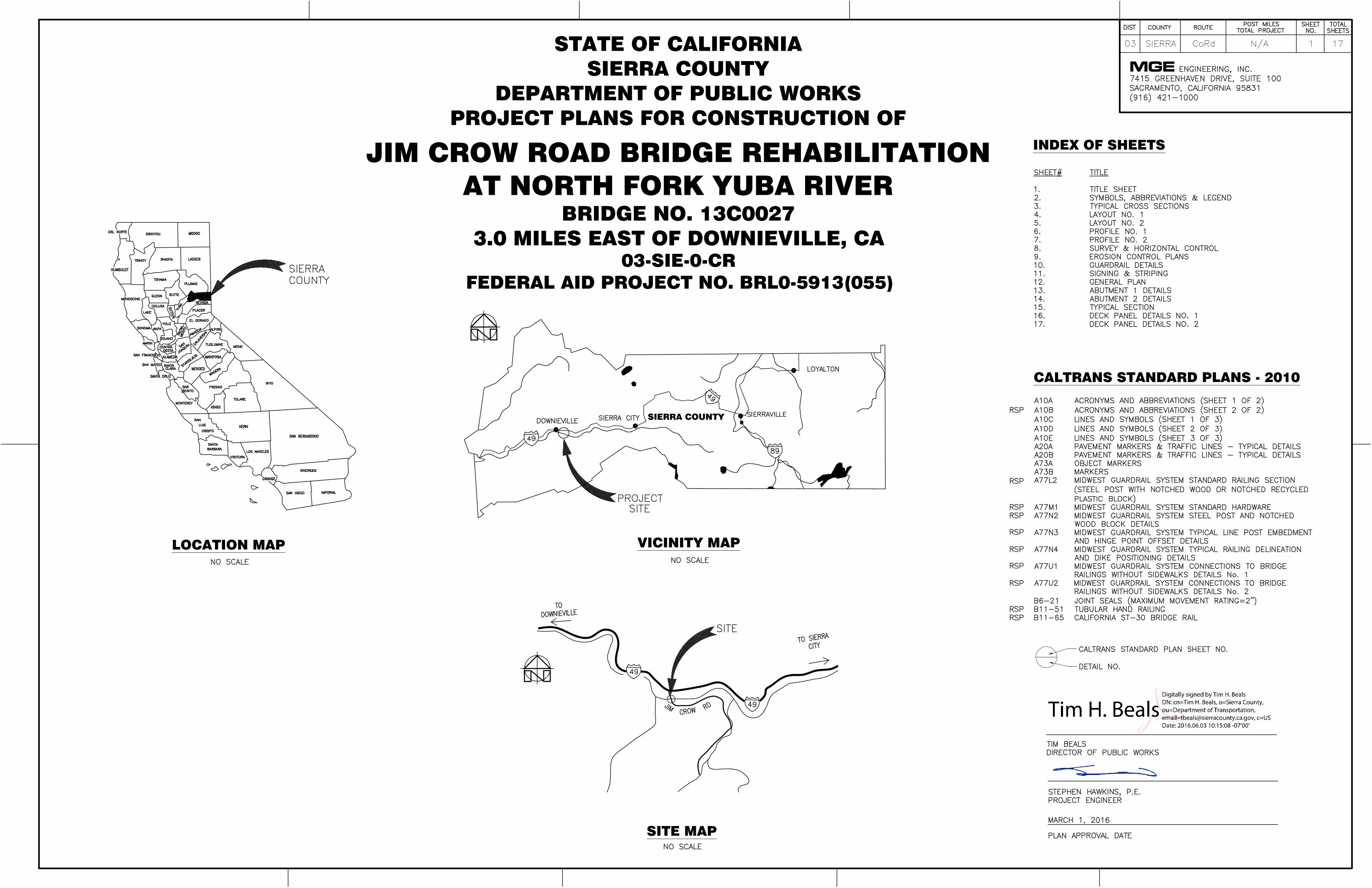
SIERRA COUNTY
SITE MAP
INDEX OF SHEETS
LOCATION MAP VICINITY MAP
MGESTATE OF CALIFORNIA
SIERRA COUNTYDEPARTMENT OF PUBLIC WORKS
PROJECT PLANS FOR CONSTRUCTION OF
JIM CROW ROAD BRIDGE REHABILITATIONAT NORTH FORK YUBA RIVER
BRIDGE NO. 13C00273.0 MILES EAST OF DOWNIEVILLE, CA
CALTRANS STANDARD PLANS - 2010
03-SIE-0-CRFEDERAL AID PROJECT NO. BRL0-5913(055)

QUANTITIES
DETAILS
DESIGN
PROJECT ENGINEER
BRIDGE NO.
POST MILE
REVISION DATES (PRELIMINARY STAGE ONLY) SHEET OF
PLANS APPROVAL DATE
13C-0027
N/A
JIM CROW BRIDGEMGE ENGINEERING, INC.
17
SYMBOLS, ABBREVIATIONS & LEGEND
AB AGGREGATE BASE
BB BEGINNING OF BRIDGE
BC BEGINNING OF HORIZONTAL CURVE
BM BENCH MARK
BVCE BEGINNING OF VERTICAL CURVE ELEVATION
BVCS BEGINNING OF VERTICAL CURVE STATION
℄ CENTERLINE
CL CLASS
CONT. CONTINUED
DIA DIAMETER
EB END OF BRIDGE
EC END OF HORIZONTAL CURVE, END CAP RAILING
EDR EMERGENCY DETOUR ROUTE
ELEV ELEVATION
EP EDGE OF PAVEMENT
EXIST, (E) EXISTING
GB GRADE BREAK
GR GUARD RAIL, EXISTING
HMA HOT MIX ASPHALT
LF LINEAR FEET
LT LEFT
MBGR METAL BEAM GUARDRAILING
MGS MIDWEST GUARDRAIL SYSTEM
Mid MIDDLE OF HORIZONTAL CURVE
NO. NUMBER
NTS NOT TO SCALE
OG ORIGINAL GROUND
PG PROFILE GRADE
PT POINT
R RADIUS
RT RIGHT
SR STATE ROAD/STATE ROUTE
STA STATION
THW TOP OF HEAD WALL, EXISTING
TOP TOP OF SLOPE
TR TRANSITION RAILING
TYP. TYPICAL
± PLUS OR MINUS
ABBREVIATIONS AND SYMBOLS LEGEND
STRIPPING LINE
EXISTING CONTOUR
CONTROL POINTS AND
PROPOSED TOP OF FILL
LIMITS OF GRADING
ORIGINAL GROUND
EXISTING TREE TO BE
CENTERLINE OF ROADWAY
CALTRANS STANDARD
DETAIL NO.
REMOVED OR PROTECTED
PLAN SHEET NO.
SURVEYING MONUMENTS
AND TOE OF FILL
LIMIT OF 95%
RELATIVE COMPACTION
PROPOSED CONTOUR3110
IN PLACE

QUANTITIES
DETAILS
DESIGN
PROJECT ENGINEER
BRIDGE NO.
POST MILE
REVISION DATES (PRELIMINARY STAGE ONLY) SHEET OF
PLANS APPROVAL DATE
13C-0027
N/A
JIM CROW BRIDGEMGE ENGINEERING, INC.
17
TYPICAL CROSS SECTIONS
TYPICAL SECTION - STA 10+53 TO 10+98
TYPICAL SECTION - STA 10+98 TO 12+62
TYPICAL SECTION - STA 12+62 TO STA 12+81 (BB)
TYPICAL BENCHING DETAIL - STA 10+98 TO 12+62

QUANTITIES
DETAILS
DESIGN
PROJECT ENGINEER
BRIDGE NO.
POST MILE
REVISION DATES (PRELIMINARY STAGE ONLY) SHEET OF
PLANS APPROVAL DATE
13C-0027
N/A
JIM CROW BRIDGEMGE ENGINEERING, INC.
17
LAYOUT
LEGEND
MA
TC
H L
INE
, S
TA
13+
00, S
EE
SH
EE
T 5
LAYOUT NO.1
CONSTRUCTION NOTES:
NOTES:
3115

QUANTITIES
DETAILS
DESIGN
PROJECT ENGINEER
BRIDGE NO.
POST MILE
REVISION DATES (PRELIMINARY STAGE ONLY) SHEET OF
PLANS APPROVAL DATE
13C-0027
N/A
JIM CROW BRIDGEMGE ENGINEERING, INC.
17
LAYOUT
LEGEND
MA
TC
H L
INE
, S
TA
13+
00, S
EE
SH
EE
T 4
LAYOUT NO.2
CONSTRUCTION NOTES:
NOTES:
3115

QUANTITIES
DETAILS
DESIGN
PROJECT ENGINEER
BRIDGE NO.
POST MILE
REVISION DATES (PRELIMINARY STAGE ONLY) SHEET OF
PLANS APPROVAL DATE
13C-0027
N/A
JIM CROW BRIDGEMGE ENGINEERING, INC.
17
PROFILE
MA
TC
H L
INE
, S
TA
13+
00, S
EE
SH
EE
T 7
PROFILE NO.1
QUANTITIES
DETAILS
DESIGN
PROJECT ENGINEER
BRIDGE NO.
POST MILE
REVISION DATES (PRELIMINARY STAGE ONLY) SHEET OF
PLANS APPROVAL DATE
13C-0027
N/A
JIM CROW BRIDGEMGE ENGINEERING, INC.
17
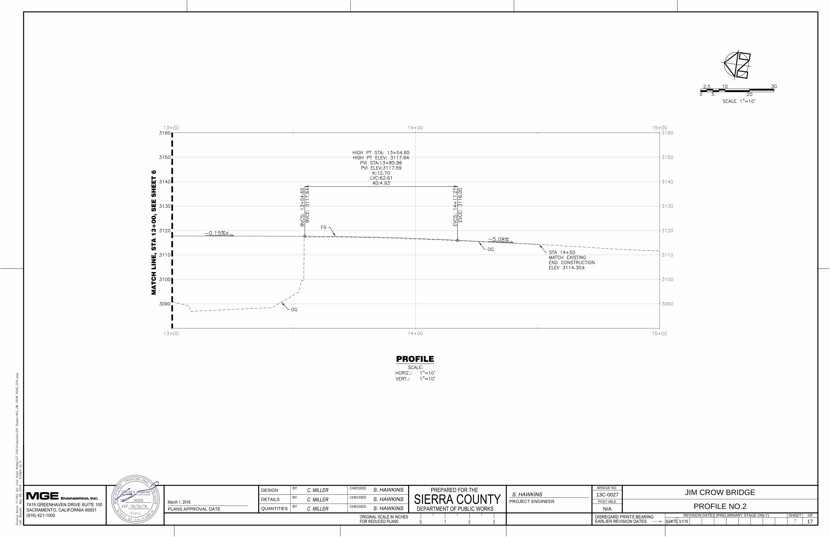
PROFILE
MA
TC
H L
INE
, S
TA
13+
00, S
EE
SH
EE
T 6
PROFILE NO.2
QUANTITIES
DETAILS
DESIGN
PROJECT ENGINEER
BRIDGE NO.
POST MILE
REVISION DATES (PRELIMINARY STAGE ONLY) SHEET OF
PLANS APPROVAL DATE
13C-0027
N/A
JIM CROW BRIDGEMGE ENGINEERING, INC.
17
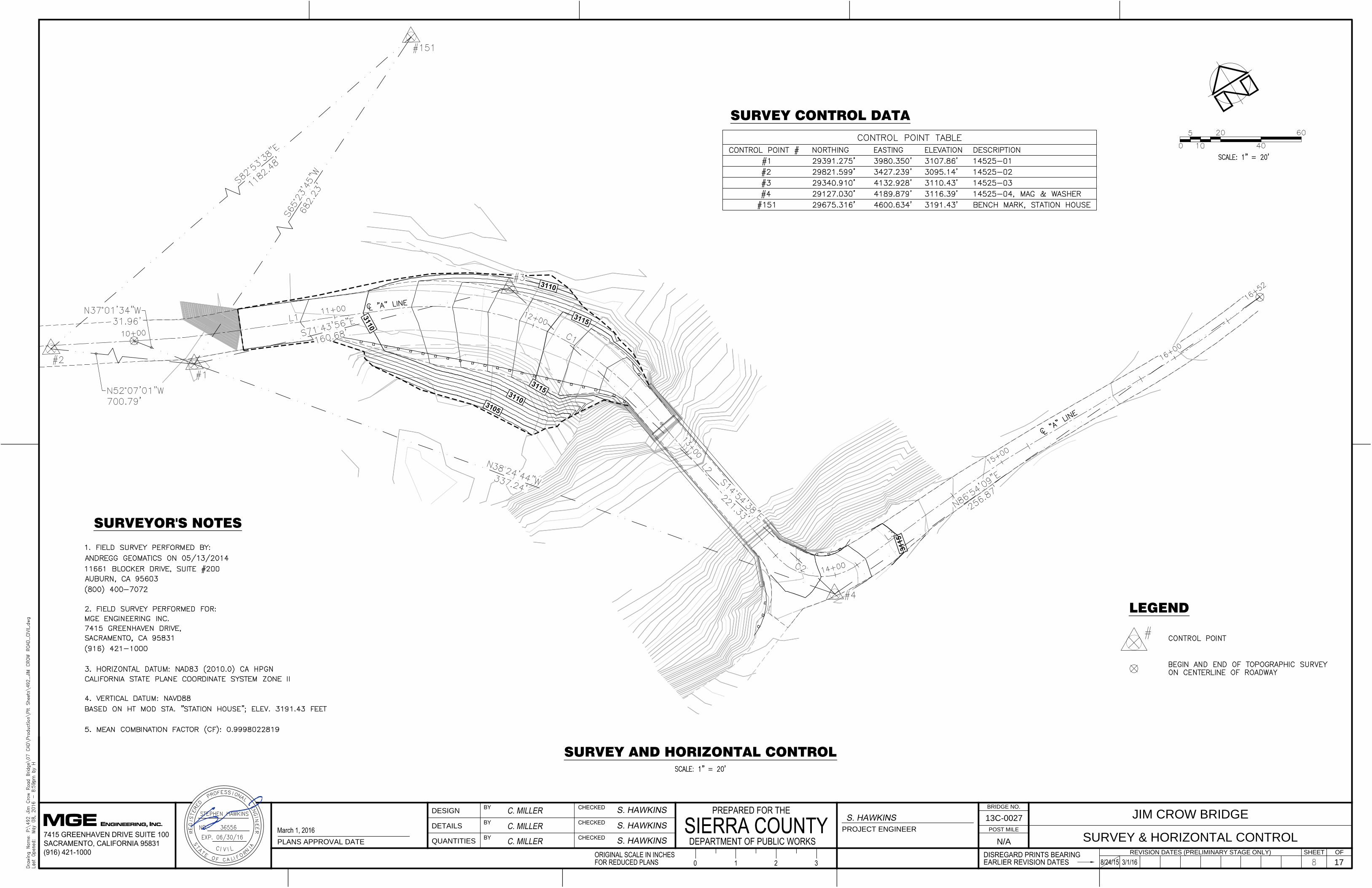
SURVEY AND HORIZONTAL CONTROL
SURVEY & HORIZONTAL CONTROL
SURVEY CONTROL DATA
SURVEYOR'S NOTES
LEGEND

QUANTITIES
DETAILS
DESIGN
PROJECT ENGINEER
BRIDGE NO.
POST MILE
REVISION DATES (PRELIMINARY STAGE ONLY) SHEET OF
PLANS APPROVAL DATE
13C-0027
N/A
JIM CROW BRIDGEMGE ENGINEERING, INC.
17
EROSION CONTROL PLANS
LEGEND
NOTES
EROSION CONTROL
TEMPORARY EROSION CONTROL

QUANTITIES
DETAILS
DESIGN
PROJECT ENGINEER
BRIDGE NO.
POST MILE
REVISION DATES (PRELIMINARY STAGE ONLY) SHEET OF
PLANS APPROVAL DATE
13C-0027
N/A
JIM CROW BRIDGEMGE ENGINEERING, INC.
17
GUARDRAIL DETAILS
GUARDRAIL DETAILS PLAN
NOTES:
LEGEND

QUANTITIES
DETAILS
DESIGN
PROJECT ENGINEER
BRIDGE NO.
POST MILE
REVISION DATES (PRELIMINARY STAGE ONLY) SHEET OF
PLANS APPROVAL DATE
13C-0027
N/A
JIM CROW BRIDGEMGE ENGINEERING, INC.
17
SIGNING AND STRIPING
SIGNING & STRIPING

MGE ENGINEERING, INC.
1/2" = 1'-0"
TYPICAL SECTION - BRIDGE REHABILITATION
±
9 1
/4
"
PG
Exist L Girder
(Composite)
P
California ST-30 Barrier
Rail, Revised Standard
Plan RSP B11-65, Typ
L Jim Crow Rd
"A" Line
C
1/2" = 1'-0"
TYPICAL SECTION - EXIST BRIDGE
± ± ±
±±
1.5±%1.5±%
PG
L Jim Crow Rd
C
8" ±
1" = 10'
PLAN
North F
ork Y
uba R
iver
EB, Sta 13+57.53±
BB, Sta 12+80.78±
1" = 10'
ELEVATION
BBEB
OG
1
:
1
±
Existing
Abutment
Existing
Abutment
Temporary Support
at Mid Span
L Jim Crow Rd
C
Elev 3117.75±
Elev 3117.64±
Abut 1
Abut 2
Toe of Slope, Typ
Toe of Slope, Typ
L A
bu
t 1
C
L A
bu
t 2
C
To Shangri-LA
LEGEND
Indicates Direction of Traffic
Indicates Direction of Flow
Indicates Bridge Removal
Shear key &
Catcher, Typ
Wingwall
Widening, Typ
Exist Deck
Removal
Exist Railing
Removal, Typ
Precast Concrete Deck
Panels (Lightweight
Conc γ=110 pcf)
A
A
Top of Slope,
Typ
MGS, See
'Road Plans'
To Hwy 49
Spot Blast Clean
& Paint Girders
3
/
4
:
1
Bridge
INDEX TO BRIDGE PLANS
Sheet No. Title
1 General Plan
2 Abutment 1 Details
3
Typical Section
4
Deck Panel Details No.1
Design:
LOAD AND RESISTANCE FACTOR DESIGN
Seismic Loading:
AASHTO LRFD Bridge Design Specifications, 6th Edition
and the Caltrans Amendments, Preface dated January
2014;
Soil Profile: Site Class B
Maximum Moment Magnitude: 6.2
Peak Ground Acceleration: 0.24g
Hl93 Design Vehicle
GENERAL NOTES
Live Loading:
Normal Concrete: 0.15 kcf
Lightweight Concrete: 0.11 kcf
Includes 0.035 ksf for Future Wearing Surface
Dead Loading:
0 0.5
0
0.1
0.2
0.3
0.4
0.5
0.6
1 1.5 2 2.5 3 3.5 4 4.5 5 5.5
Period (s)
Sp
ectra
l A
cce
le
ra
tio
n S
a(g
)
ARS
Clear
±
Concrete: f = 60 ksi (Epoxy Coated)
f' = 5 ksi
= 150 pcf (Normal Concrete)
= 110 pcf (Lightweight Concrete)
y
c
Structural Steel: ASTM A709 Grade 50: f = 50 ksi (New Construction)
ASTM A36: f =36 ksi (Assumed for Evaluation of
Existing Structure
y
y
Const Joint
8"
Tubular Hand
Railing (Modified), Typ
Typ
Indicates Temporary Support
MGS, See
'Road Plans'
1.2%
1.2%
Note:
The Contractor must verify all controlling field dimensions
before ordering or fabricating any material.
Abutment 2 Details
Deck Panel Details No.2
5
6
Loadings for Temporary Support:
Unfactored DL: 95.0 kips
Unfactored LL: 110.0 kips
Lateral Load: 19.0 kips
5% Damping
"A" Line
Seismic Design: Caltrans Seismic Design Criteria (SDC), Version 1.7, April, 2013
Lightweight Concrete
Barrier Curb
Scupper

1/2" = 1'-0"
ABUTMENT 1 PLAN
1/2" = 1'-0"
SECTION A-A
Exist Wingwall
Approach
Roadway
Exist Railing to
be Removed
California ST-30
Barrier Rail, Typ
#5 Drill & Bond
Dowels, Total 3
@ 12 in 6" Deep
Holes.
#4 Tot 9
1
:
1
1/2" = 1'-0"
ABUTMENT 1 ELEVATION
New Shear Key
& Catcher, Typ
Existing
Abutment
Exist End
Diaphragm
Exist Fixed
Bearing
P
8 1
/2
"
Typ
±
9"
Typ
L Jim Crow Rd
C
B
B
SECTION B-B
Shear key &
Catcher, Typ
Existing
Abutment
±
Add new End
Diaphragm
C12 x 30
MGE ENGINEERING, INC.
L Jim Crow Rd
C
Existing
Abutment
New Shear Key
& Catcher, Typ
Exist Wingwall, Typ
L Abut 1
C
A A
Top Exist
Pedestal
3
1
3
1
2
Notes:
1. The Contractor must verify all controlling field dimensions
before ordering or fabricating any material.
2. For Detail B, see "ABUTMENT 2 DETAILS"sheet.
13
C
C
SECTION C-C
Shear key &
Catcher, Typ
Existing
Abutment
Add new End
Diaphragm
C12 x 30
Exist Fixed
Bearing
3
1
#5 Drill & Bond
Dowels, Total 3 @
12 in 6" Deep Holes
#5 Drill & Bond
Dowels, Total 3 @
12 in 6" Deep Holes
#5, Total 9
#4 @ 12
#4 @ 12 , Max
#4 @ 12
#4 @ 12 , Max
20'-0" ±, Typ
Exist End
Diaphragm
Exist End
Diaphragm
1/2" = 1'-0"1/2" = 1'-0"
1" = 1'-0"
DETAIL A
Detail A
Exist End
Diaphragm
Add new End
Diaphragm
C12 x 30
2"
Exist Bearing
Stiffeners L
P
7
8
" High Strength
Bolts (3)
2
1
2
"
Exist
7
8
" High
Strength Bolts
Exist Girder
New 5" x 1" Shear
Studs @ 12", Typ
3" = 1'-0"
NEW SHEAR CONNECTOR DETAIL
2" 4" 4" 2"
5"
Add New End
Diaphragm
C12 x 30
Exist L Girder
(Composite)
3"
D D
1/2" = 1'-0"
SECTION D-D
Approach
Roadway
2'-1
"
1'-0"
#5 @ 12
#5 TOT 4
#5 @12
#4 @12
3"
3/8" = 1'-0"
EXIST SHEAR STUD REMOVAL
3/8" = 1'-0"
NEW SHEAR STUD INSTALLATION
Exist Girder
Exist Girder
New 5" x 1" Shear
Studs, Typ
Exist Shear Stud Removal
Exist Girder
1
1
2
" ±
3" ± 3" ± 3" ±
1
1
2
" ±
4" ±
Exist Shear Stud Removal
3" = 1'-0"
EXIST SHEAR CONNECTOR DETAIL
Exist Girder
6"
6"
1'-0"
Precast Concrete
Intermediate Deck
Panels (3'-11")
1'-0"
Precast
Concrete End
Deck Panels
(3'-6
1
2
")
#5 @12
#4 @12
3'-6
" , T
yp
Conc End Wall,
Typ
Detail B
Detail B
1'-3
"
1'-0
"
1'-0
"
#5 @ 12 Drill &
Bond Dowels in 6"
Deep Holes.

8 1
/2
"
Add New End
Diaphragm
C12 x 30
Exist End
Diaphragm
Exist L Girder
(Composite)
P
9"
Typ
New Shear Key
& Catcher, Typ
F
F
L Jim Crow Rd
C
Typ
1/2" = 1'-0"
SECTION F-F
Shear key &
Catcher, Typ
Existing
Abutment
Add new End
Diaphragm
C12 x 30
MGE ENGINEERING, INC.
1/2" = 1'-0"
ABUTMENT 2 PLAN
1/2" = 1'-0"
ABUTMENT 2 ELEVATION
L Jim Crow Rd
C
Exist Wingwall, Typ
Existing
Abutment
New Shear Key
& Catcher, Typ
L Abut 2
C
G G
Top Exist
Pedestal
Exist Fixed
Bearing
3
1
3
Notes:
1. For Detail A, see "ABUTMENT 1 DETAILS" sheet.
2. The Contractor must verify all controlling field dimensions
before ordering or fabricating any material.
14
E
E
1/2" = 1'-0"
SECTION E-E
Shear key &
Catcher, Typ
Existing
Abutment
Add new End
Diaphragm
C12 x 30
Exist
Expansion
Bearing
3
1
#4 @ 12
#4 @ 12 , Max
#5 Drill & Bond
Dowels, Total 3 @
12 in 8" Deep Holes
#4 @ 12
#4 @ 12 , Max
#5 Drill & Bond
Dowels, Total 3 @
12 in 8" Deep Holes
Exist End
Diaphragm
Exist End
Diaphragm
7'-8
3
8
" ±, Typ
1
4
'-
6
1
4
"
±
,
T
y
p
1/2" = 1'-0"
SECTION G-G
Exist Wingwall
Approach
Roadway
Exist Railing to
be Removed
California ST-30
Barrier Rail, Typ
#5 Drill & Bond
Dowels, Total 3
@ 12 in 8" Deep
Holes.
#4 Tot 9
1
:
1
3
1
Detail A
Detail B
Detail B
Conc End Wall, Typ
3
'-
6
"
,
T
y
p
1 1/2" = 1'-0"
DRILL & BOND DOWEL DETAIL
1 1/2" = 1'-0"
DETAIL B
4" T
yp
3
1
Top of Exist Conc
Exist Abut
Backwall
Type A Seal
2"
1"
1" Clr
Precast Deck
Panel
#5 Drill & Bond
Dowels @ 12 in 8"
Deep Holes.

MGE ENGINEERING, INC.
9 1
/4
"
PG
Exist L Girder
(Composite)
P
L Jim Crow Rd
C
±
#6 @ 12
#4 @ 12
#7 @ 6
#7 @ 6
#5 @ 6
2"
Clr
1 1
/2
"
Clr
6"
3/4" Drip
Groove, Typ
California ST-30
Barrier Rail, Typ
1" = 1'-0"
TYPICAL SECTION
3/4" = 1'-0"
PANEL LONGITUDINAL REINFORCING SPLICE DETALS
B
B
3" = 1'-0"
DETAIL "A"
8"
Const Joint
Cast - In - Place Curb,
Precast Concrete
Deck Panels
8 Spaces @ 9 1/2"
Detail "A"
6"
3"
3"
A A
3" = 1'-0"
SECTION A-A
3" = 1'-0"
SECTION B-B
Longitudinal
Reinf
1/4" x 3" Studs
Typ
1/4" x 3" Studs
4" Clr
Longitudinal
Reinf (Lapped)
#7 Trans Reinf
Concrete Fill
Built - Up Steel
Channel (Galvanized)
#7 Trans Reinf
Longitudinal
Reinf (Lapped)
1 1
/4
"
Built - Up Steel
Channel
Backer Rod
End Plate1/4" x 3" Studs
1 1
/4
"
1"
New 5" x 1" Shear
Studs, Typ
L Detail "A"
C
2" 2"
L Detail "A"
C
1"
Typ
Concrete Fill
4
Notes:
1. All reinforcing steel to be epoxy coated.
2. The Contractor must verify all controlling field dimensions before
ordering or fabricating any material.
3. For location of scuppers, see "DECK PANEL DETAILS NO. 1" sheet.
4. For tubular hand railing details not shown, see "DECK PANEL
DETAILS NO. 2" sheet.
5. Precast concrete deck panels and cast-in-place curbs must be
lightweight concrete.
#4 @ 9
1
2
#6 @ 9
1
2
Exist 12"
Wide Girder
Flange, Typ
Scupper, See
Note 3, Typ
Blockout, Typ
15
Tubular Hand
Railing (Modified),
Typ. See Note 4
Concrete Fill
1" , T
yp
B11-65
-
RSP
B11-65
-
RSP

MGE ENGINEERING, INC.
L A
bu
t 1
C
L A
bu
t 2
C
Intermediate Precast Slab Panels B Total 17 = 68'-1"
±
±
13+00 13+50
1" = 5'
DECK PANEL LAYOUT - PLAN
L Jim Crow Rd
C
1" = 1'-0"
INTERMEDIATE DECK PANEL DETAILS - PLAN
1" = 1'-0"
DECK PANEL DETAILS - ELEVATION
5 1
/2
"5
1
/2
"
3" x 11" Voids for
Shear Studs, Typ
End Precast Slab Panel A
9 1
/4
"
8"
L Jim Crow Rd
C
Exist Girder, Typ
2 1
/2
"2
1
/2
"
7 S
pa
ce
s @
6
"
4"
Typ
#7 @ 6, Tot 8
End Precast Slab Panel A
Typ
1"
13 + 50
5
16
Notes:
1. All reinforcing steel to be epoxy coated.
2. The Contractor must verify all controlling field dimensions
before ordering or fabricating any material.
1'-0
"
4'-3" 4'-3"
Typ
L Girder = L Voids
C C
L Girder = L Voids
C C
#4 & # 6 @ 12 ", Typ
Extension of
Reinf, Typ
#5 @ 6,
Typ
Location of
scupper, Typ
LEGEND
Indicates Panel Type
A
Exist Steel Girder, Typ
#4 & # 6 @ 9
1
2
"

MGE ENGINEERING, INC.
1" = 1'-0"
END DECK PANEL DETAILS - PLAN
6
17
Notes:
1. All reinforcing steel to be epoxy coated.
2. The Contractor must verify all controlling field dimensions
before ordering or fabricating any material.
5 1
/2
"
2 1
/2
"2
1
/2
"
5 S
pa
ce
s @
6
"
4"
Typ
#7 Tot 8
#4 & # 6 @ 12 ", Typ
4'-3"4'-3"
L Girder = L Voids
C C
L Girder = L Voids
C C
#5
2 S
pa
ce
s E
Q
1'-0
"
Typ
Extension of
Reinf, Typ
#4 & # 6 @ 9
1
2
"
3'-6
1
2
" ±
1 1/2" = 1'-0"
HAND RAILING DETAILS
1'-1
0"
8"
8"
6"
2"
4"
2"
Note:
For details not shown, see .
B11-51
_
L 1/2" Bolts w/
Washers & Nuts, Typ
C
TS 2 x 2 x 3/16
TS 2 x 2 x 3/16 Post
TS 2 x 2 x 3/16
TS 3 x 2 x 3/16