job aids for field replacements (frus) for the avaya s8500 ... · job aids for field replacements...
TRANSCRIPT

Job Aids for Field Replacements (FRUs) for the Avaya S8500 Server
03-300529Issue 4
January 2008

© 2007 Avaya Inc.All Rights Reserved.
NoticeWhile reasonable efforts were made to ensure that the information in this document was complete and accurate at the time of printing, Avaya Inc. can assume no liability for any errors. Changes and corrections to the information in this document may be incorporated in future releases.
For full legal page information, please see the complete document, Avaya Legal Page for Hardware Documentation, Document number 03-600759.To locate this document on our website, simply go to http://www.avaya.com/support and search for the document number in the search box.
Documentation disclaimerAvaya Inc. is not responsible for any modifications, additions, or deletions to the original published version of this documentation unless such modifications, additions, or deletions were performed by Avaya. Customer and/or End User agree to indemnify and hold harmless Avaya, Avaya's agents, servants and employees against all claims, lawsuits, demands and judgments arising out of, or in connection with, subsequent modifications, additions or deletions to this documentation to the extent made by the Customer or End User.
Link disclaimerAvaya Inc. is not responsible for the contents or reliability of any linked Web sites referenced elsewhere within this documentation, and Avaya does not necessarily endorse the products, services, or information described or offered within them. We cannot guarantee that these links will work all of the time and we have no control over the availability of the linked pages.
WarrantyAvaya Inc. provides a limited warranty on this product. Refer to your sales agreement to establish the terms of the limited warranty. In addition, Avaya’s standard warranty language, as well as information regarding support for this product, while under warranty, is available through the following Web site:http://www.avaya.com/support
Copyright Except where expressly stated otherwise, the Product is protected by copyright and other laws respecting proprietary rights. Unauthorized reproduction, transfer, and or use can be a criminal, as well as a civil, offense under the applicable law.
Avaya supportAvaya provides a telephone number for you to use to report problems or to ask questions about your product. The support telephone number is 1-800-242-2121 in the United States. For additional support telephone numbers, see the Avaya Web site:http://www.avaya.com/support

03-300529 Issue 4 January 2008 3
Job Aid: Replacing the Avaya S8500/B/C server . . . . . . . . . . . . . 9Required Equipment. . . . . . . . . . . . . . . . . . . . . . . . . . . . . . . . . . 9Pre-site tasks. . . . . . . . . . . . . . . . . . . . . . . . . . . . . . . . . . . . . . 10Initial on-site tasks. . . . . . . . . . . . . . . . . . . . . . . . . . . . . . . . . . . 11Replacing the S8500/B/C server . . . . . . . . . . . . . . . . . . . . . . . . . . . 13Hard drive . . . . . . . . . . . . . . . . . . . . . . . . . . . . . . . . . . . . . . . 16
Using the blank hard drive . . . . . . . . . . . . . . . . . . . . . . . . . . . . 16Re-using the original hard drive . . . . . . . . . . . . . . . . . . . . . . . . . 21
Replacing the S8500 server . . . . . . . . . . . . . . . . . . . . . . . . . . . . . . 22Powering down and disconnecting the S8500 server . . . . . . . . . . . . . . 23Removing the S8500 server from the rack . . . . . . . . . . . . . . . . . . . . 23Removing the cover of the S8500 server. . . . . . . . . . . . . . . . . . . . . 23Reusing the S8500 server’s hard drive. . . . . . . . . . . . . . . . . . . . . . 24Reusing the Remote Supervisor Adapter . . . . . . . . . . . . . . . . . . . . 27Reusing the optional network interface card (S8500) . . . . . . . . . . . . . . 30Replacing the cover on the replacement S8500 server . . . . . . . . . . . . . 32Installing the replacement S8500 server in the rack . . . . . . . . . . . . . . 32Checking for network activity on the S8500 . . . . . . . . . . . . . . . . . . . 32Confirming the original Ethernet configuration (S8500) . . . . . . . . . . . . 33Preparing the failed server for shipment. . . . . . . . . . . . . . . . . . . . . 33Expanded Procedures . . . . . . . . . . . . . . . . . . . . . . . . . . . . . . . 34Enable RAM disk. . . . . . . . . . . . . . . . . . . . . . . . . . . . . . . . . . 41
Replacing the S8500B server . . . . . . . . . . . . . . . . . . . . . . . . . . . . . 43Powering down and disconnecting the S8500B server . . . . . . . . . . . . . 43Removing the S8500B server from the rack . . . . . . . . . . . . . . . . . . . 44Removing the cover of the S8500B server . . . . . . . . . . . . . . . . . . . . 44Reusing the hard drive (S8500B) . . . . . . . . . . . . . . . . . . . . . . . . . 45Reusing the SAMP (S8500B) . . . . . . . . . . . . . . . . . . . . . . . . . . . 47Reusing the optional network interface card (S8500B) . . . . . . . . . . . . . 49Replacing the cover on the replacement S8500B server . . . . . . . . . . . . 51Installing the replacement S8500B server in the rack. . . . . . . . . . . . . . 51Powering up the S8500B server . . . . . . . . . . . . . . . . . . . . . . . . . 52Checking network activity on the S8500B server . . . . . . . . . . . . . . . . 52Preparing the failed server for shipment. . . . . . . . . . . . . . . . . . . . . 53Installing Communication Manager on the S8500B server . . . . . . . . . . . 53Installing service pack files on the S8500B server . . . . . . . . . . . . . . . 55Disable RAM disk . . . . . . . . . . . . . . . . . . . . . . . . . . . . . . . . . 55Restoring the system files (S8500B) . . . . . . . . . . . . . . . . . . . . . . . 56Enable RAM disk. . . . . . . . . . . . . . . . . . . . . . . . . . . . . . . . . . 58Verifying the S8500B server configuration . . . . . . . . . . . . . . . . . . . 58
Contents

Contents
4 Job Aids for Field Replacements (FRUs) for the Avaya S8500 Server
Replacing the S8500C server . . . . . . . . . . . . . . . . . . . . . . . . . . . . . 59Powering down and disconnecting the S8500C server . . . . . . . . . . . . . 59Removing the S8500C server from the rack . . . . . . . . . . . . . . . . . . . 60Removing the cover of the S8500C server . . . . . . . . . . . . . . . . . . . . 60Reusing the hard drive (S8500C) . . . . . . . . . . . . . . . . . . . . . . . . . 61Reusing the SAMP (S8500C) . . . . . . . . . . . . . . . . . . . . . . . . . . . 64Reusing the dual NIC (S8500C) . . . . . . . . . . . . . . . . . . . . . . . . . . 66Replacing the cover on the replacement S8500C server . . . . . . . . . . . . 67Installing the replacement S8500C server in the rack. . . . . . . . . . . . . . 68Powering up the S8500C server . . . . . . . . . . . . . . . . . . . . . . . . . 68Checking network activity on the S8500C server . . . . . . . . . . . . . . . . 68Preparing the failed S8500C server for shipment . . . . . . . . . . . . . . . . 69Installing the software on the S8500C server . . . . . . . . . . . . . . . . . . 70Installing service pack files on the S8500C server . . . . . . . . . . . . . . . 71Disable RAM disk . . . . . . . . . . . . . . . . . . . . . . . . . . . . . . . . . 73Restoring the system files (S8500C) . . . . . . . . . . . . . . . . . . . . . . . 73Enable RAM disk. . . . . . . . . . . . . . . . . . . . . . . . . . . . . . . . . . 75Verifying the S8500C server configuration . . . . . . . . . . . . . . . . . . . 75
Job Aid: Replacing the Hard Drive on the Avaya S8500 server . . . . . . . . . . . . . . . . . . . . . . . . . . . . . 77
Required equipment . . . . . . . . . . . . . . . . . . . . . . . . . . . . . . . . . . 77Pre-site tasks. . . . . . . . . . . . . . . . . . . . . . . . . . . . . . . . . . . . . . 78Hard drive considerations. . . . . . . . . . . . . . . . . . . . . . . . . . . . . . . 79Tasks to replace the hard drive . . . . . . . . . . . . . . . . . . . . . . . . . . . . 79Final tasks . . . . . . . . . . . . . . . . . . . . . . . . . . . . . . . . . . . . . . . 80Replacing the hard drive in the S8500 server . . . . . . . . . . . . . . . . . . . . 85
Replacing the hard drive in the S8500C server . . . . . . . . . . . . . . . . . 85Replacing the hard drive in the S8500B server . . . . . . . . . . . . . . . . . 87Replacing the hard drive in the S8500 server . . . . . . . . . . . . . . . . . . 88
Expanded Procedures . . . . . . . . . . . . . . . . . . . . . . . . . . . . . . . . . 91Installing Communication Manager . . . . . . . . . . . . . . . . . . . . . . . 92Installing post-upgrade patch files . . . . . . . . . . . . . . . . . . . . . . . . 93Enable RAM disk. . . . . . . . . . . . . . . . . . . . . . . . . . . . . . . . . . 95Restoring the system files . . . . . . . . . . . . . . . . . . . . . . . . . . . . 96Verifying the server configuration . . . . . . . . . . . . . . . . . . . . . . . . 98
Job Aid: Replacing the SAMP on the Avaya S8500 Series server . . . . 99Replacing the SAMP on the Avaya S8500C server . . . . . . . . . . . . . . . . . 99

Contents
03-300529 Issue 4 January 2008 5
Powering down the S8500C server . . . . . . . . . . . . . . . . . . . . . . . . 100Removing the S8500C server from the rack . . . . . . . . . . . . . . . . . . . 100Removing the cover of the S8500C server . . . . . . . . . . . . . . . . . . . . 100Removing and replacing the SAMP card in the S8500C server . . . . . . . . 101Replacing the cover of the S8500C server . . . . . . . . . . . . . . . . . . . . 103Reconnecting the cables to the S8500C server . . . . . . . . . . . . . . . . . 103Powering up the S8500C server . . . . . . . . . . . . . . . . . . . . . . . . . 104Reconfiguring the SAMP card on the S8500C server . . . . . . . . . . . . . . 104S8500C server connections . . . . . . . . . . . . . . . . . . . . . . . . . . . . 105S8500C services access and logins . . . . . . . . . . . . . . . . . . . . . . . 110
Replacing the SAMP on the Avaya S8500B server . . . . . . . . . . . . . . . . . 114Powering down the S8500B server . . . . . . . . . . . . . . . . . . . . . . . . 114Removing the S8500B server from the rack . . . . . . . . . . . . . . . . . . . 115Removing the cover of the S8500B server . . . . . . . . . . . . . . . . . . . . 115Removing and replacing the SAMP card on the S8500B server . . . . . . . . 116Replacing the cover of the S8500B server . . . . . . . . . . . . . . . . . . . . 118Reconnecting cables on the S8500B server . . . . . . . . . . . . . . . . . . . 119Powering up the S8500B server . . . . . . . . . . . . . . . . . . . . . . . . . 119Reconfiguring the SAMP card on the S8500B server . . . . . . . . . . . . . . 120S8500B server connections . . . . . . . . . . . . . . . . . . . . . . . . . . . . 121S8500B services access and logins . . . . . . . . . . . . . . . . . . . . . . . 129
Job Aid: Replacing the SAMP power supply . . . . . . . . . . . . . . . 135Replacing the SAMP power supply on the S8500C server . . . . . . . . . . . . . 135
Removing the old SAMP power supply from the S8500C. . . . . . . . . . . . 135Replacing the SAMP power supply from the S8500C . . . . . . . . . . . . . . 136
Replacing the SAMP power supply on the S8500B server . . . . . . . . . . . . . 136Removing the old power supply from the S8500B . . . . . . . . . . . . . . . 136Replacing the power supply from the S8500B. . . . . . . . . . . . . . . . . . 137
Job Aid: Replacing the Avaya S8500 dual network interface. . . . . . . 139Check Ethernet interface settings . . . . . . . . . . . . . . . . . . . . . . . . . . 140Backing up the server . . . . . . . . . . . . . . . . . . . . . . . . . . . . . . . . . 141Powering down the server . . . . . . . . . . . . . . . . . . . . . . . . . . . . . . 142Removing the cover of the server . . . . . . . . . . . . . . . . . . . . . . . . . . 142Removing the fan unit (S8500 only) . . . . . . . . . . . . . . . . . . . . . . . . . 146Removing the old network interface card . . . . . . . . . . . . . . . . . . . . . . 146Installing the new network interface card . . . . . . . . . . . . . . . . . . . . . . 146

Contents
6 Job Aids for Field Replacements (FRUs) for the Avaya S8500 Server
Installing the new network interface card in the S8500C server . . . . . . . . 147Installing the new network interface card in the S8500B server . . . . . . . . 148Installing the new network interface card in the S8500 server . . . . . . . . . 149
Replacing the fan unit (S8500 only) . . . . . . . . . . . . . . . . . . . . . . . . . 151Replacing the cover and cabling . . . . . . . . . . . . . . . . . . . . . . . . . . . 151Powering up the server . . . . . . . . . . . . . . . . . . . . . . . . . . . . . . . . 151Checking LED activity on the dual network interface card . . . . . . . . . . . . . 152Configuring the NIC . . . . . . . . . . . . . . . . . . . . . . . . . . . . . . . . . . 154Ethernet interface mapping . . . . . . . . . . . . . . . . . . . . . . . . . . . . . . 155
Release 3.1 Ethernet configurations . . . . . . . . . . . . . . . . . . . . . . . 156Release 3.0 Ethernet configurations . . . . . . . . . . . . . . . . . . . . . . . 156Release 2.2 Ethernet configurations . . . . . . . . . . . . . . . . . . . . . . . 157Testing connectivity to customer’s network. . . . . . . . . . . . . . . . . . . 159
Job Aid: Replacing the USB modem . . . . . . . . . . . . . . . . . . . . 161Removing the old modem. . . . . . . . . . . . . . . . . . . . . . . . . . . . . . . 161Replacing the modem . . . . . . . . . . . . . . . . . . . . . . . . . . . . . . . . . 161
Job Aid: Replacing the IP Server Interface . . . . . . . . . . . . . . . . 163Removing the IPSI circuit pack . . . . . . . . . . . . . . . . . . . . . . . . . . . . 163Replacing the IPSI circuit pack . . . . . . . . . . . . . . . . . . . . . . . . . . . . 164Re-assigning a static IP address on the IPSI circuit pack . . . . . . . . . . . . . 164Assigning DHCP addressing . . . . . . . . . . . . . . . . . . . . . . . . . . . . . 165
Job Aid: Replacing the S8500 Compact Flash reader and card . . . . . 167Required equipment . . . . . . . . . . . . . . . . . . . . . . . . . . . . . . . . . . 167Remove the defective card drive . . . . . . . . . . . . . . . . . . . . . . . . . . . 167Replace the card drive. . . . . . . . . . . . . . . . . . . . . . . . . . . . . . . . . 167Replace the Compact Flash card . . . . . . . . . . . . . . . . . . . . . . . . . . . 168
Job Aid: Replacing the Remote Supervisor Adapter (RSA) . . . . . . . 169Backing up the RSA . . . . . . . . . . . . . . . . . . . . . . . . . . . . . . . . 170Backing up the server . . . . . . . . . . . . . . . . . . . . . . . . . . . . . . . 173Powering down the server and RSA . . . . . . . . . . . . . . . . . . . . . . . 176Removing the cover of the server . . . . . . . . . . . . . . . . . . . . . . . . 177Replacing the ribbon cable . . . . . . . . . . . . . . . . . . . . . . . . . . . . 178Removing the adapter support bracket and riser connector . . . . . . . . . . 178
Contents
03-300529 Issue 4 January 2008 7
Installing the new RSA card. . . . . . . . . . . . . . . . . . . . . . . . . . . . 180Replacing the cover of the server . . . . . . . . . . . . . . . . . . . . . . . . 180Connecting the cables to the RSA . . . . . . . . . . . . . . . . . . . . . . . . 181Powering up the server . . . . . . . . . . . . . . . . . . . . . . . . . . . . . . 181Restoring the RSA configuration . . . . . . . . . . . . . . . . . . . . . . . . . 181Upgrading the RSA firmware . . . . . . . . . . . . . . . . . . . . . . . . . . . 183Checking the RSA installation . . . . . . . . . . . . . . . . . . . . . . . . . . 185Restoring the RSA defaults . . . . . . . . . . . . . . . . . . . . . . . . . . . . 186

Contents
8 Job Aids for Field Replacements (FRUs) for the Avaya S8500 Server

03-300529 Issue 4 January 2008 9
Job Aid: Replacing the Avaya S8500/B/C server
! Important:Important: Always check the Avaya Support Website for Product Support Notices at
http://support.avaya.com and select Product Support Notices (All Avaya products) in the MOST POPULAR PRODUCTS IN SUPPORT section.
This job aid describes the steps required to replace an Avaya S8500, an S8500B, or an S8500C servers running Avaya Communication Manager software.
The hard drive in the replacement server comes blank, and you have these choices:
l If you are using this blank hard drive, you must install the software from the CD-ROM that the customer received from an earlier installation of Communication Manager software. The software CD-ROM contains the Linux operating system and the appropriate release of Avaya Communication Manager.
l If the hard drive in the failed server is good, you can replace the blank hard drive in the replacement server with the old hard drive.
This job aid has different procedures for replacing the various S8500 servers:
l Replacing the S8500 server on page 22
l Replacing the S8500B server on page 43
l Replacing the S8500C server on page 59
Required EquipmentVerify that you have the following equipment and tools on site:
l Replacement S8500 server
l Customer’s CD-ROM with the software load (if not reusing the hard drive)
l Ethernet crossover cable for direct connection of your laptop to the server
l Flat-head screwdriver
l Cross-point (Phillips) screwdriver
l Electrostatic wrist ground strap and mat

Job Aid: Replacing the Avaya S8500/B/C server
10 Job Aids for Field Replacements (FRUs) for the Avaya S8500 Server
Pre-site tasksBefore you go on site, verify that the following tasks are done.
l Ask the customer for the Product ID for the server being replaced. If the customer does not have it, run the Automatic Registration Tool (ART) to obtain the Product ID number and port number (customer dial-up) for the replacement server.
l If the customer is using SNMP for alarming, you will need to get the IP addresses and community names from the customer because the SNMP programming is not saved after the replacement.
l If using the blank hard drive that comes with the server, verify that you have the correct software and software service pack. You must install the software on the replacement server, and you might need to install a software service pack.
l If using the blank hard drive that comes with the server, verify that you have the current Communication Manager license and Avaya authentication files to install on the replacement server. Go to the Remote Feature Activation (RFA) Web site to get them (http://rfa.avaya.com).
l Verify that the customer has a recent backup of all the system and translation files. This is critical if the hard drive is not functional.
l Verify with the customer that you have access permissions to backup and restore the data from the network server.
Pre-site tasks for replacing an S8500/B/C server
Task Description
1 Obtain CD with the correct software release
Retrieve customer’s original CD containing Communication Manager.
2 Get software service pack, if appropriate
The Communication Manager software service pack file might be available on the CD. Otherwise, download it to your laptop from the Avaya Support Web site (http://support.avaya.com/). Select Downloads then choose S8500 server.
3 Get SAMP software update Avaya Support Web site (http://support.avaya.com/)
4 Get all configuration information for the server
Examples include IP addresses, server name, DNS information, and so forth.

Initial on-site tasks
03-300529 Issue 4 January 2008 11
Initial on-site tasksl If the hard drive in the failed server is good, go to Initial tasks for replacing an S8500/B/C
server reusing the original hard drive on page 11.
l If the hard drive is not functional, make sure the customer has a recent backup of the system files and translations that you can restore after you have replaced the hard drive. If not, the server needs to be reconfigured and translations input as if it were a new installation. See Installing and Configuring the Avaya S8500 server (03-300143) for detailed procedures. Additionally, some illustrations of software installation and configuration information appear later in this document.
Initial tasks for replacing an S8500/B/C server reusing the original hard drive
Task Description
1 Log onto Maintenance Web Interface
Connect a crossover cable to the services port on the back of the server. Open a browser on your laptop. Type 192.11.13.6 and press Enter to log onto the Maintenance Web Interface as craft or dadmin.
2 Determine the software release and any software service packs
Under Server, click Software Version. Note the software release and any installed software service packs.
3 Determine if the customer has a recent backup of data
Under Data Backup/Restore, select Backup Logs to search for recent backup files. Check for the types of data and dates. Verify that there is a recent, successful backup of the system files and translations.
4 Record alarms and verify hard drive functionality
Under Alarms, click Current Alarms. Note alarms on the server not related to the hard drive.In the Server alarms section, check the Source Listing column for a HARD DISK entry. If it is there, then the hard drive is failing and cannot be reused (see Determining if a hard drive is functional on page 34).
1 of 3

Job Aid: Replacing the Avaya S8500/B/C server
12 Job Aids for Field Replacements (FRUs) for the Avaya S8500 Server
5 Back up the system files If the customer does not have a recent backup, you must back up the files so they can be restored later.
1. Under Data Backup/Restore, click Backup Now.2. Select Server and System Files, Security
Files, Avaya Call Processing (ACP) Translations, and Save ACP translations prior to backup.
3. Select the backup method normally used.4. Click Start Backup to begin the back up
process.
6 Record the OSS numbers (used when the system dials out to report alarms)
If the customer does not have these numbers, open a command line session to the server.
1. Type almenable and press Enter.2. Record the numbers.3. Type exit and press Enter to close the session.
7 Suppress alarm origination At the Linux command line type almsuppress -t 120 and press Enter to suppress alarms for the duration of the replacement process. (Maximum time is 2 hours.)
8 Shut down the server If the hard drive is functional, under Server, click Shutdown This Server then unclick Restart Server after Shutdown. Press the power-control button on the front of the server. The internal fan shuts off.Caution: Do not unplug a functioning server without stopping all processes first. Failure to do this corrupts the hard drive. This is especially important if you are reusing the hard drive.Caution: Do not hold down the power button for more than a split second. Holding the button down too long causes the server to reboot.
9 Power down the server Disconnect the power cord from the back of the server.
10 Unplug the RSA/SAMP Disconnect the power cord from the RSA/SAMP.
11 Disconnect the modem Disconnect the modem from the RS-232 port on the RSA or from the USB port on the SAMP.
12 Disconnect the LAN connection from the RSA/SAMP
Disconnect and label the LAN connection (if used) from the Ethernet port on the RSA/SAMP
Initial tasks for replacing an S8500/B/C server reusing the original hard drive (continued)
Task Description
2 of 3

Replacing the S8500/B/C server
03-300529 Issue 4 January 2008 13
Replacing the S8500/B/C server
13 Disconnect the cable from the dual NIC (if used)
Disconnect and label the cable from the Ethernet port on the dual NIC (if used).
14 Disconnect the crossover cable
Disconnect the crossover cable from the services port on the back of the server.
Initial tasks for replacing an S8500/B/C server reusing the original hard drive (continued)
Task Description
3 of 3
Tasks for replacing an S8500/B/C server
Task Description
1 Shut down the server If the hard drive is functional, under Server, click Shutdown This Server then unclick Restart Server after Shutdown. Press the power-control button on the front of the server. The internal fan shuts off.Caution: Do not unplug a functioning server without stopping all processes first. Failure to do this corrupts the hard drive. This is especially important if reusing the hard drive.Caution: Do not hold down the power button for more than a split second. Holding the button down too long causes the server to reboot.
2 Unplug the server Once the server is completely shut down, unplug the power cords from the server and RSA/SAMP.Caution: Do not unplug a functioning server without stopping all processes first. Failure to do this corrupts the hard drive. This is especially important if reusing the hard drive.Disconnect and label the LAN connections from the Ethernet ports on the RSA/SAMP and dual NIC (if used).Disconnect all attached devices, including the laptop, both modems, and the external flashcard reader (if used).
1 of 3

Job Aid: Replacing the Avaya S8500/B/C server
14 Job Aids for Field Replacements (FRUs) for the Avaya S8500 Server
3 Remove the server from the rack
l S8500: see Removing the S8500 server from the rack on page 23.
l S8500B: see Removing the S8500B server from the rack on page 44.
l S8500C: Removing the S8500C server from the rack on page 60.
4 Remove the cover of the server
l S8500: see Removing the cover of the S8500 server on page 23.
l S8500B: see Removing the cover of the S8500B server on page 44.
l S8500C: Removing the cover of the S8500C server on page 60.
5 Replace components in the replacement server
Replace the RSA or SAMP with the original one from the failed server:
l S8500: see Reusing the Remote Supervisor Adapter on page 27
l S8500B: see Reusing the SAMP (S8500B) on page 47.
l S8500C: see Reusing the SAMP (S8500C) on page 64.
If the failed server has the optional dual NIC, you must move it to the replacement server.
l S8500: see Reusing the optional network interface card (S8500) on page 30.
l S8500B: see Reusing the optional network interface card (S8500B) on page 49.
l S8500C: NIC required and installed in replacement server.
If the hard drive in the failed server is good, you must replace the one in the replacement server with the original one from the failed server.
l S8500: see Reusing the S8500 server’s hard drive on page 24.
l S8500B: see Reusing the hard drive (S8500B) on page 45.
l S8500C: Reusing the hard drive (S8500C) on page 61
6 Replace the cover of the replacement server
l S8500: see Replacing the cover on the replacement S8500 server on page 32.
l S8500B: see Replacing the cover on the replacement S8500B server on page 51.
l S8500C: Replacing the cover on the replacement S8500C server on page 67.
Tasks for replacing an S8500/B/C server (continued)
Task Description
2 of 3

Replacing the S8500/B/C server
03-300529 Issue 4 January 2008 15
7 Install the replacement server into the rack
l S8500: see Installing the replacement S8500 server in the rack on page 32.
l S8500B: see Installing the replacement S8500B server in the rack on page 51.
l S8500C: Installing the replacement S8500C server in the rack on page 68.
8 Note: Skip this step if reusing the original hard drive.Insert the software CD in the CD-ROM drive of the server, if using the blank hard drive
Open the CD-ROM drawer and place the Communication Manager CD in the drawer and close it.The software CD contains boot software that the server automatically accesses when you power up the server.
9 Reconnect attached devices
Reconnect the LAN connections to the Ethernet ports on the RSA/SAMP and dual NIC (if used).Reconnect all attached devices, including the laptop, both modems, and the external flashcard reader (if used).
10 Power up the server Plug the power cords into the server and RSA. Press the power-control button on the front of the server.Note: Wait at least 3 minutes for the server to complete its power up. Watch the power-on LED on the server.
11 Note: Skip this step if using a new hard drive.Test the hard drive by logging onto the Maintenance Web Interface.
Connect a crossover cable to the services port on the back of the server. Open a browser on your laptop. Type 192.11.13.6 and press Enter to log onto the Maintenance Web Interface as craft or dadmin. Log in as craft or dadmin.Under Server, click Status Summary and note the information concerning the hard drive.
Tasks for replacing an S8500/B/C server (continued)
Task Description
3 of 3

Job Aid: Replacing the Avaya S8500/B/C server
16 Job Aids for Field Replacements (FRUs) for the Avaya S8500 Server
Hard drivel If you cannot reuse the original hard drive, you must install the Linux operating system and
Avaya Communication Manager on the new, blank hard drive, then restore the backed up system files. Follow the procedure in Using the blank hard drive on page 16.
l If you are reusing the original hard drive, follow the procedure in Re-using the original hard drive on page 21.
Using the blank hard driveUsing this procedure means that you are not re-using the old hard drive.
Final tasks for replacing an S8500/B/C server using the blank hard drive
Task Description
1 Disconnect the RJ45 cable Disconnect the Ethernet RJ45 crossover cable from the Services port on the server.
2 Clear ARP cache on laptop if you cannot log in
From a DOS command line, type arp -d 192.11.13.6 and press Enter.
3 Connect laptop to the RSA/SAMP card
l RSA: connect to the Ethernet port (see Note Figure 5: S8500 rear panel on page 33) using a crossover cable
l SAMP: see Figure 11: S8500B rear panel on page 52 or Figure 16: S8500C rear panel on page 69.
4 Log into the RSA/SAMP card
Open a browser on your laptop. Type 192.11.13.6 and press Enter to log into the RSA/SAMP.Note: Use the initial installation craft login and the initial RSA password.
5 Set a timeout value l RSA: On the RSA welcome screen, on the Inactive session timeout value field, select no timeout and click Continue. This allows 60 minutes of use before disconnecting.
l SAMP: At the home page select Controls. Select boot protection timer. Select a value of 0. Click on set control. Logout of the SAMP.
6 RSA (S8500) only: set the loader watchdog timeout
Under ASM Control, click System Settings. Scroll down to the Server Timeouts section, and in the Loader watchdog field, select disabled and click Save.
1 of 6

Hard drive
03-300529 Issue 4 January 2008 17
7 Log off the RSA/SAMP Click Log Off.
8 Disconnect the RSA/SAMP LAN cable
Disconnect the Ethernet RJ45 cable from the RSA/SAMP Ethernet port.
9 Connect laptop to the server
Connect a crossover cable to the services port on the back of the server and wait about 3 minutes from the time you boot up the server before trying to access the information on the CD.
10 Clear ARP cache on laptop From a DOS command line, type arp -d 192.11.13.6 and press Enter.
11 Set display parameters (if necessary)
At the DOS command line type telnet and press Enter.At the Telnet prompt type unset crlf and press Enter.Type display and press Enter to verify that message says Sending only CRType exit and press Enter to close the session.
12 Install Communication Manager
You must install the software from the CD. l For procedure details for an S8500, see Installing
the software on the S8500 server on page 36.l For procedure details for an S8500B, see
Installing Communication Manager on the S8500B server on page 53.
l For procedure details for an S8500C, see Installing the software on the S8500C server on page 70.
13 Log onto the Maintenance Web Interface
Open a browser on your laptop. Type 192.11.13.6 and press Enter to log onto the Maintenance Web Interface. Log in as craft or dadmin.Note: Use the initial installation login craft and the initial password.
14 Set alarm suppression on the server
At the Linux command line type almsuppress -y and press Enter to enable alarm suppression.
15 Check software version on the Maintenance Web page
Under Server, click Software Version to verify the Communication Manager release.
16 Copy files to the server Copy the license and Avaya authentication files and the software service pack file, if any, to the server.Under Miscellaneous, click Download Files.Browse to select the file for downloading and click Download.
Final tasks for replacing an S8500/B/C server using the blank hard drive (continued)
Task Description
2 of 6

Job Aid: Replacing the Avaya S8500/B/C server
18 Job Aids for Field Replacements (FRUs) for the Avaya S8500 Server
17 Configure the network parameters and verify connectivity (optional)
Note: if you used the local Compact Flash for the most recent backup, you can skip this step.You must re-administer the Ethernet port connecting to the customer’s network.Under Server Configuration, click Configure Server and click Continue.Click Continue through the pages until you get to the Specify how you want to use this wizard page. Select Configure individual services and click Continue. Click Set Identities and make assignments for the use of the Ethernet ports and click ContinueFill in the correct IP address, Gateway, and Subnet mask for the Corporate LAN interface (the S8500 server will be restored from a backup obtained from a remote server on the network). Select AUTOSENSE for all Ethernet ports. Click Change. Close the window.Under Diagnostics, click Ping. Type the IP address of the server where the files are backed up and click Execute Ping to verify that you can access the customer’s network.
18 Restore the system files and translationsIf there were no backup files, configure the server
Disable RAM disk on the server (sudo ramdisk -v -f disabled) and confirm with ramdisk -v -s.Under Servers, click Software Version. Note the Release String data.Under Data Backup/Restore, click View/Restore Data.Caution: Do not restore files if they are from a software load different from the load now running on the server.Match the Release String data from the Software Version page with the listing provided.
l For procedure details for an S8500, see Restoring the S8500 system files on page 39.
l For procedure details for an S8500B, see Restoring the system files (S8500B) on page 56.
l For procedure details for an S8500C, see Restoring the system files (S8500C) on page 73.
See Installing and Configuring the Avaya S8500 server, 03-300143, for more information.
19 Verify date and time Under Server, click Server Date/Time. Make changes as necessary.
Final tasks for replacing an S8500/B/C server using the blank hard drive (continued)
Task Description
3 of 6

Hard drive
03-300529 Issue 4 January 2008 19
20 Install software service pack, if any
You might need to install a software service pack.l For procedure details for an S8500, see Installing
service pack files on the S8500 server on page 38.l For procedure details for an S8500B, see
Installing service pack files on the S8500B server on page 55.
l For procedure details for an S8500C, see Installing service pack files on the S8500C server on page 71.
Note: Skip this procedure if there is no software service pack file to install.
21 Verify that the service pack is installed
Under Server, click Software Version to verify the software service pack versions.
22 Verify server configuration l For procedure details for an S8500, see Verifying the S8500 server configuration on page 42
l For procedure details for an S8500B, see Verifying the S8500B server configuration on page 58.
l For procedure details for an S8500C, see Verifying the S8500C server configuration on page 75.
Note: If there was no backup file to restore, you must reconfigure the server. Get the configuration data from the customer.
23 Install the license and Avaya authentication files
Under Security, click Authentication File and select “Install the Authentication file I previously downloaded” and click Install.
24 Log in from the SAT Log in as craft.
25 Check the translations Using the SAT screen, type list configuration all and press Enter and check that all the hardware displays.
26 Test the hard drive by logging onto the Maintenance Web Interface
Connect a crossover cable to the services port on the back of the server. Open a browser on your laptop. Type 192.11.13.6 and press Enter to log onto the Maintenance Web Interface as craft or dadmin.Under Server, click Status Summary and note the information concerning the hard drive.
27 Ping the connections on the server
Under Diagnostics, click Ping. Ensure that all connections, IPSI boards, and all administered connections respond.
Final tasks for replacing an S8500/B/C server using the blank hard drive (continued)
Task Description
4 of 6

Job Aid: Replacing the Avaya S8500/B/C server
20 Job Aids for Field Replacements (FRUs) for the Avaya S8500 Server
28 Resolve alarms on the server
Under Alarms, click Current Alarms. Compare these against the recorded alarms from Checklist 2, step 4. Clear any alarms that appear.Using a SAT screen, type display alarms and press Enter.For instructions on resolving alarms, see Maintenance Alarms for Avaya Communication Manager 3.1, Media Gateways and Servers, 03-300430.
29 Check the health of the server
Using a SAT screen, type list ipserver-interface and status health. Check that all connections are working correctly.
30 Save translations Note: If this server is an ESS or LSP, skip this step.Using a SAT screen, type save translation and press Enter to back them up.
31 Set the Product ID on the server
Confirm the product ID of the server, and, if necessary, set the product ID with the productid -p product_id command.
32 Administer backup schedule on the server
Under Data Backup/Restore, click Schedule Backup to re-administer the server’s backup schedule.
33 Back up files on the server Under Data Backup/Restore, click Backup Now.Click Start Backup to begin the back up process.
34 Release alarm suppression on the server
At the Linux command line type almsuppress -n and press Enter to release alarm suppression.Note: Only do this if you want to release it before the time that you set earlier expires (maximum of 2 hours).
35 Log off all administration applications
When you have completed all the administration, log off the server.
36 Disconnect from the server Disconnect the laptop from the server.
37 RSA only: Clear ARP cache on laptop if you cannot log in
From a DOS command line, type arp -d 192.11.13.6 and press Enter.
38 RSA only: Connect laptop to the RSA card
Connect to the Ethernet port (to the right of the serial connector) on the back of the RSA card using a crossover cable.
Final tasks for replacing an S8500/B/C server using the blank hard drive (continued)
Task Description
5 of 6

Hard drive
03-300529 Issue 4 January 2008 21
Re-using the original hard driveUsing this procedure means that you are re-using the original hard drive.
39 RSA only: Log into the RSA card
Open a browser on your laptop. Type 192.11.13.6 and press Enter to log into the RSA.Note: Use the initial installation craft login and the initial RSA password.
40 RSA only: Set a timeout value
On the RSA welcome screen, on the Inactive session timeout value field, select no timeout and click Continue. This allows 60 minutes of inactivity before disconnecting.
41 RSA only: Set the loader watchdog timeout
Under ASM Control, click System Settings. Scroll down to the Server Timeouts section, and in the Loader watchdog field, select 5.0 (minutes) and click Save.
42 RSA only: Log off and disconnect from the RSA
Click Log Off. Once you are logged off, disconnect from the services port on the RSA.
Final tasks for replacing an S8500/B/C server using the blank hard drive (continued)
Task Description
6 of 6
Final tasks for replacing an S8500/B/C server reusing the original hard drive
Task Description
1 Connect laptop to the server
Connect to the services port on the back of the server.
2 Log onto the Maintenance Web Interface
Open a browser on your laptop. Type 192.11.13.6 and press Enter to log onto the Maintenance Web Interface.
3 Verify date and time Under Server, click Server Date/Time. Make changes as necessary.
4 Ping the connections on the server
Under Diagnostics, click Ping. Ensure that all administered connections respond.
1 of 2

Job Aid: Replacing the Avaya S8500/B/C server
22 Job Aids for Field Replacements (FRUs) for the Avaya S8500 Server
Replacing the S8500 serverWhen replacing a failed S8500 server, there may be several components that can be reused. These include the hard drive, Remote Supervisor Adapter (RSA), and network interface card (NIC), if being used. If these components are serviceable, we recommend that you remove them from the failed server and install them in the replacement server. For specific removing and replacing information see:
l Reusing the S8500 server’s hard drive on page 24
l Reusing the Remote Supervisor Adapter on page 27
l Reusing the optional network interface card (S8500) on page 30
5 Resolve alarms on the server
Under Alarms, click Current Alarms. Compare these against the recorded alarms from Checklist 3, step 2. Clear any alarms that appear.Using a SAT screen, type display alarms and press Enter.For instructions on resolving alarms, see Maintenance Alarms for Avaya Communication Manager 3.1, Media Gateways and Servers, 03-300430.
6 Check the health of the server
Using a SAT screen, type list ipserver-interface and status health. Check that all connections are working correctly.
7 Set the Product ID on the server
Confirm the product ID using the productid -p product_id and press Enter, where product_id is the product ID that you received from the customer or the ART tool. Since the hard drive is being re-used, the product ID will be on the hard drive.
8 Release alarm suppression on the server
At the Linux command line type almsuppress -n and press Enter to release alarm suppression.Note: Only do this if you want to release it before the time you set earlier runs out (maximum of 2 hours)
9 Log off all administration applications
When you have completed all the administration, log off the server.
Final tasks for replacing an S8500/B/C server reusing the original hard drive (continued)
Task Description
2 of 2
Replacing the S8500 server
03-300529 Issue 4 January 2008 23
Powering down and disconnecting the S8500 serverTo power down the S8500 server:
! CAUTION:CAUTION: Do not unplug a functioning server without stopping all processes first. Failure to
do this will corrupt the hard drive.
1. If the server is functional, type stop -h -f on the command line or use the Web page to shut down the server.
2. If Step 1 does not work, press the power button to shut off the server.
! CAUTION:CAUTION: Do not hold down the power button for more than a split second. Holding the
button down too long causes a reboot of the server.
3. Unplug the power cord from the back of the server.
4. Unplug the power cord from the RSA.
5. Unplug the USB modem cable.
6. Label and disconnect the modem from the RS-232 port on the RSA.
7. Label and disconnect the LAN connection (if used) from the Ethernet port on the RSA.
8. Label and disconnect the cable from the Ethernet port on the dual NIC (if used).
Removing the S8500 server from the rackTo remove the S8500 server from the rack.
1. Pull the server forward so the server rails expand and the retaining clips on the rails click into place.
2. Using the cross-point (Phillips) screwdriver, remove the server from the slide rails in the rack.
Removing the cover of the S8500 serverFor these steps see Removing and replacing the cover on the S8500 server on page 24.
1. Set the server down on a flat surface with an electrostatic mat.
2. Loosen the two captive screws on the back of the server that hold the cover in place.
Job Aid: Replacing the Avaya S8500/B/C server
24 Job Aids for Field Replacements (FRUs) for the Avaya S8500 Server
3. Slide the server cover back from the front panel until the cover’s tabs are released from the top slot of the front panel.
4. Lift the cover straight up and remove it from the server.
Figure 1: Removing and replacing the cover on the S8500 server
Reusing the S8500 server’s hard driveIf the hard drive in the failed S8500 server is still good, then you want to reuse it in the replacement server. Use the following process to swap the hard drives:
l Removing the hard drive from the failed S8500 server on page 25
l Removing the hard drive from the replacement S8500 server on page 26
l Installing the original hard drive in the replacement S8500 server on page 27
Figure notes:
1. Captive screws on server
h3mscaps LAO 070103
disc
1
Replacing the S8500 server
03-300529 Issue 4 January 2008 25
! CAUTION:CAUTION: Wear an anti-static wrist ground strap whenever handling components such as
the hard drive of an Avaya S8500 server. Connect the strap to an approved ground, such as an unpainted metal surface. Also, place the hard drive on an anti-static mat that is similarly grounded. Do not place the new or the old drive on a bare surface.
Removing the hard drive from the failed S8500 server
For these steps, see Removing and replacing the drive cage (S8500) on page 26.
1. Locate the drive cage in the left-hand corner of the front of the server.
2. Use the two black pull handles on the ribbon cables to unplug the data connectors from the back of the CD-ROM and hard drive.
3. Push the ribbon cable back out of the way.
4. Unplug the two power connectors from the back of the CD-ROM drive and the hard drive. You must release the power connector on the CD-ROM drive by gently bending the side spring clip holding it in place.
5. Loosen the captive screw next to the drive cage.
6. Slide the drive cage toward the back of the server to clear the retaining hooks.
7. Place the drive cage on the antistatic mat.
8. Remove the four screws (two on each side) securing the hard drive in the drive cage and remove the hard drive.

Job Aid: Replacing the Avaya S8500/B/C server
26 Job Aids for Field Replacements (FRUs) for the Avaya S8500 Server
Figure 2: Removing and replacing the drive cage (S8500)
Removing the hard drive from the replacement S8500 server
To remove the hard drive from the replacement S8500 server.
1. Remove the cover from the replacement server. See Removing the cover of the S8500 server on page 23.
2. Remove the hard drive from the replacement server. See Removing the hard drive from the failed S8500 server on page 25.
Figure notes:
1. Drive bay housing drive cage2. Ribbon cable attached to hard drive3. Power cable connected to the CD-ROM
drive4. Captive screw holding drive cage
5. Tabs6. Screws holding hard drive in drive cage7. Hard drive8. Drive cage
h3msdrv3 KLC 020204
1
2
3
5
6
6
disc
8
7
4
6

Replacing the S8500 server
03-300529 Issue 4 January 2008 27
Installing the original hard drive in the replacement S8500 server
For these steps, see Figure 2: Removing and replacing the drive cage (S8500) on page 26.
1. Insert the original hard drive into the drive cage so that the connectors are in the same direction as the CD-ROM connectors and the screw holes are aligned.
2. Reinsert the 4 screws (2 on each side) to attach the hard drive to the drive cage.
3. Reattach the flat ribbon cable (in 2 places) to the hard drive and CD-ROM drive.
4. Reattach the 2 power cables to the hard drive and CD-ROM drive.
5. Slide the drive cage into place in the server, making sure that it fits securely into the retaining hooks and finger-tighten the captive screw.
6. Make sure the drive cage is secure and that the cables are not bunched or blocking the fan unit.
Reusing the Remote Supervisor Adapter
Note:Note: The RSA is in the S8500 server only.
If the Remote Supervisor Adapter (RSA) card in the failed server is still good, then you want to reuse it in the replacement server. Use the following process to switch the RSAs.
l Removing the RSA from the failed S8500 server on page 27
l Removing the RSA from the replacement S8500 server on page 29
l Installing the original RSA in the replacement S8500 server on page 29
! CAUTION:CAUTION: Wear an anti-static wrist ground strap whenever handling components such as
the RSA board of an Avaya S8500 server. Connect the strap to an approved ground, such as an unpainted metal surface. Also, place the RSA board on an anti-static mat that is similarly grounded. Do not place the new or the old drive on a bare surface.
Removing the RSA from the failed S8500 server
To remove the RSA from the failed S8500 server.
1. Remove the cover of the server. See Removing the cover of the S8500 server on page 23.
2. Remove one side of the ribbon cable from the system-management connector on the RSA.

Job Aid: Replacing the Avaya S8500/B/C server
28 Job Aids for Field Replacements (FRUs) for the Avaya S8500 Server
Note:Note: The RSA card resides in PCI-X slot 1 located under the adapter support bracket.
Remove the adapter support bracket and the riser connector together.
3. Loosen the captive screw located to the right of the slot labeled PCI 1.
4. The riser connector must be removed by pulling straight up on the adapter support bracket. Place one finger under the screw on the far end of the riser connector and one finger under the adapter support bracket near the captive screw and pull straight up, as shown in Figure 3.
Figure 3: Removing and replacing the Remote Supervisor Adapter (S8500 only)
5. Remove the RSA card from PCI-X slot 1 by pulling the card gently out of the riser card connector.
Figure notes:
1. Remote Supervisor Adapter2. Adapter support bracket3. Riser card connector
4. Connector5. Captive screw
h3msrrsa LAO 071803
1
2
LINKTX/RX
LINKTX/RX
PCI1
PCI 2
100-127 -, 3,0A, 50/60 Hz
200-240 -, 1,5A, 50/60 Hz
133 MHz/64 Bit, 100 MHz/64 Bit
1
2
3
4
5

Replacing the S8500 server
03-300529 Issue 4 January 2008 29
Removing the RSA from the replacement S8500 server
To remove the RSA from the replacement S8500 server.
1. Remove the cover of the server. See Removing the cover of the S8500 server on page 23.
2. Remove the RSA from the replacement server. See Removing the RSA from the failed S8500 server on page 27.
Installing the original RSA in the replacement S8500 server
To install the original RSA in the replacement S8500 server.
1. Carefully grasp the original RSA by the top edges or upper corners, component side facing up, and align it with the PCI-X slot 1 opening in the replacement server. Press the RSA firmly into the riser card connector. See Figure 3: Removing and replacing the Remote Supervisor Adapter (S8500 only) on page 28.
! CAUTION:CAUTION: Make sure the RSA card is completely and correctly seated in the riser card
connector before you turn on the S8500 server. Incomplete insertion might cause damage to the system board or RSA card.
2. Connect the ribbon cable to the system-management connector located on the back of the card.
3. Replace the adapter support bracket lining up the tabs on each side of the bracket and the screw holes on the riser card connector.
4. Align the riser card with the connector and the tabs on the adapter support bracket with the provided holes and press the riser card firmly into the connector.
5. Finger-tighten the captive screw to the right of the slot.
6. If you are re-using the optional dual network interface, go to Reusing the optional network interface card (S8500) below.
If you are not using the dual network interface, go to Replacing the cover on the replacement S8500 server on page 32.

Job Aid: Replacing the Avaya S8500/B/C server
30 Job Aids for Field Replacements (FRUs) for the Avaya S8500 Server
Reusing the optional network interface card (S8500)If the optional network interface card (NIC) in the failed server is being used and still good, then you want to reuse it in the replacement S8500 server. Use the following process to swap the NIC.
! CAUTION:CAUTION: Wear an anti-static wrist ground strap whenever handling components such as
the hard drive of an Avaya S8500 server. Connect the strap to an approved ground, such as an unpainted metal surface. Also, place the hard drive on an anti-static mat that is similarly grounded. Do not place the new or the old drive on a bare surface.
Removing the NIC from the failed S8500 server
For these steps, see Figure 4: Removing and replacing the NIC (S8500 only) on page 31.
1. Locate the fan slot adjacent to the power plug on the rear of the server.
2. Remove the two screws holding the fan unit. You do not need to unplug the fan unit.
3. Set the adapter-support bracket to the right of the fan.
4. Completely unscrew the captive screw on the left hand side of the PCI-2 slot.
The captive screw is now loose so that you can flip it up. You will need this space to maneuver the NIC out of its slot.
5. Firmly pull the NIC out of its slot.

Replacing the S8500 server
03-300529 Issue 4 January 2008 31
Figure 4: Removing and replacing the NIC (S8500 only)
Installing the NIC in the replacement S8500 serverFor these steps, see Figure 4.
1. Carefully grasp the NIC by the top edge or upper corners and align it with the PCI-2 expansion slot. Press the NIC firmly into the expansion slot.
! WARNING:WARNING: Be sure that the NIC is completely and correctly seated in the PCI-2 expansion
slot of the S8500 server. Incomplete insertion might cause damage to the system board or the NIC.
2. Position the faceplate so that it fits in the PCI-2 slot using the captive screw to hold it in place.
Figure notes:
1. Mounting screws2. Fan assembly3. Captive screws
4. Smaller faceplate5. Network interface card
PCI1
PCI 2
100-127 -, 3,0A, 50/60 Hz
200-240 -, 1,5A, 50/60 Hz
133 MHz/64 Bit, 100 MHz/64 Bit
h3msrnic LAO 080103
1
23
4
5
Job Aid: Replacing the Avaya S8500/B/C server
32 Job Aids for Field Replacements (FRUs) for the Avaya S8500 Server
Replacing the cover on the replacement S8500 serverFor these steps, see Figure 1: Removing and replacing the cover on the S8500 server on page 24.
1. Place the cover onto the replacement S8500 server.
2. Slide the cover forward so the covers’ tabs slide into place under the top slots of the front panel.
3. Finger-tighten the captive screws on the back of the server.
Installing the replacement S8500 server in the rack
Note:Note: This procedure is for the S8500 server.
The following steps install the server in the rack.
1. Install the server onto the slide rails in the rack.
2. Locate the marked cable that you removed from the NIC (if used) and plug it into the NIC.
3. Connect the USB modem cable.
4. Connect the LAN connection (if used) to the Ethernet port on the RSA.
5. Connect the serial modem to the RS-232 port on the RSA.
6. Connect the power cord to the RSA.
7. Connect the power cord to the back of the server.
8. Push back into place.
See Quick Start for Hardware Installation: Avaya S8500 server for more information on installing the S8500 server in the rack and reconnecting all the cables.
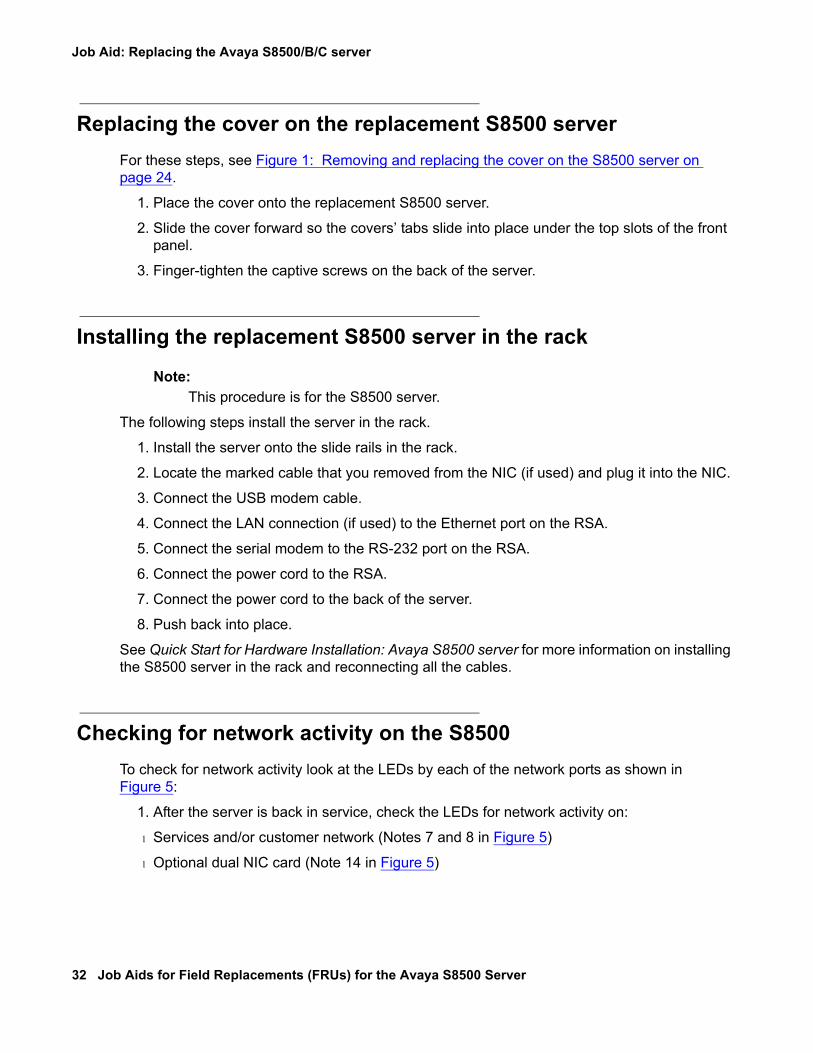
Checking for network activity on the S8500To check for network activity look at the LEDs by each of the network ports as shown in Figure 5:
1. After the server is back in service, check the LEDs for network activity on:
l Services and/or customer network (Notes 7 and 8 in Figure 5)
l Optional dual NIC card (Note 14 in Figure 5)

Replacing the S8500 server
03-300529 Issue 4 January 2008 33
Figure 5: S8500 rear panel
Confirming the original Ethernet configuration (S8500)After the server is back in service, check the original Ethernet configuration settings.
1. Go to the Configure Server Web page.
2. Confirm that the server’s Ethernet configuration settings are the same as before.
Preparing the failed server for shipmentThe following steps prepare the server for return shipment to Avaya:
1. Insert the new hard drive from the replacement server into the drive cage so that the connectors are in the same direction as the CD-ROM connectors and the screws holes are aligned (see Figure 2: Removing and replacing the drive cage (S8500) on page 26).
2. Reinsert the four screws (two on each side) to attach the hard drive to the drive cage.
3. Reattach the flat ribbon cable (in two places) to the hard drive and CD-ROM drive.
4. Reattach the two power cables to the hard drive and CD-ROM drive.
5. Slide the drive cage into place making sure that it fits securely into the retaining hooks and finger-tighten the captive screw.
Figure notes:
1. External power-supply connector for RSA
2. Power LED for RSA3. Error LED for RSA4. Serial connector for RSA modem5. Ethernet RJ45 connector on RSA6. 9-pin RS232 connector7. Services port
8. Connection to customer network9. Video port (not used)
10. Mouse connector (not used)11. Keyboard connector (not used)12. System error LED13. Power-on LED14. Optional dual network interface card
(NIC)
1 2
LINK TX/RX LINK TX/RX
PCI1
PCI 2100-127 -, 3,0A, 50/60 Hz200-240 -, 1,5A, 50/60 Hz
133 MHz/64 Bit, 100 MHz/64 Bit
7
2 4 5
68912
h3msble3 LAO 102804
1 3
13 11 10
14

Job Aid: Replacing the Avaya S8500/B/C server
34 Job Aids for Field Replacements (FRUs) for the Avaya S8500 Server
6. Make sure the drive cage is secure and that the cables are not bunched or blocking the fan unit.
! CAUTION:CAUTION: Be sure the ribbon cable is pushed completely inside the server and is not
bunched, pinched, or caught between the top of the hard drive and the hard drive slot.
7. Replace the cover and tighten the captive screws (see Figure 1: Removing and replacing the cover on the S8500 server on page 24.
8. Return the defective server to Avaya.
Expanded Procedures
Determining if a hard drive is functional
Note:Note: This procedure is for the S8500 server.
There are occasions when the defective server may have a functional hard drive. To determine if the hard drive in the defective server is functional:
1. On the defective server, connect the laptop cross-over cable to the Ethernet RJ45 port on the RSA card (see Connector panel on the Remote Supervisor Adapter on page 34 for locations of the connectors and components of the RSA).
Figure 6: Connector panel on the Remote Supervisor Adapter
2. Open a web browser to the RSA card and in the Address field, type 192.11.13.6 and press Enter.The system displays the Enter Network Password window.
Figure notes:
1. Clip2. External power-supply connector3. Power and error LEDs
4. ASM RS-485 RJ14 connector5. Serial connector6. Ethernet RJ45 connector
h3msrsap LAO 071503
1 2 3 4 5 6

Replacing the S8500 server
03-300529 Issue 4 January 2008 35
3. In the Enter Network Password window, in the User Name field, type craft and in the Password field, type the password (same as the server password) and press Enter.The system displays the Welcome window.
4. On the Welcome window, click Continue.
5. On the navigation pane, click Event Log.
6. On the Event Log window, look for red boxes in the Sev(everity) column. This indicates problems that need attention. A fatal server failure should be near the top of the Event Log.
If there is no mention of a hard drive failure, you can presume the hard drive is operational and can be moved to the replacement server.
7. Remove the defective server. See Removing the S8500 server from the rack on page 23.
8. Remove the hard drive from the defective server. See Removing the hard drive from the failed S8500 server on page 25.
9. Remove the hard drive from the replacement server. See Removing the hard drive from the replacement S8500 server on page 26.
10. Install the hard drive from the replacement server. See Installing the original hard drive in the replacement S8500 server on page 27.
11. Install the replacement server. See Installing the replacement S8500 server in the rack on page 32.
12. Connect the laptop cross-over cable to the Ethernet RJ45 port on the RSA card.

Job Aid: Replacing the Avaya S8500/B/C server
36 Job Aids for Field Replacements (FRUs) for the Avaya S8500 Server
13. On the server, press Power and wait for the operating system to come up.
14. Open a web browser to the RSA card and in the Address field, type 192.11.13.6 and press Enter.
15. In the Enter Network Password window, in the User Name field, type craft and in the Password field, type the password:
l If the RSA is from the replacement server, type the default password.
l Otherwise, type the same password as the server.
Press Enter.This RSA card is new to the S8500 server and has not been configured for the customer.
16. On the Welcome window, click Continue.
17. On the navigation pane, click System Health.
18. On the System Health Summary section, monitor the Server State field until it changes to “OS booted.” Verify “Server is operating normally” is green.
Periodically refresh the screen by clicking System Health on the navigation pane.
If the "Server is operating normally" changes from green to red before the Server State field says "OS booted," click Event Log.
Installing the software on the S8500 server
The following steps install the software on the S8500 server.
1. Connect the services laptop to services port (Eth1) on the rear of the server.
2. Connect to 192.11.13.6 and press Enter to view the first screen.
Note:Note: To navigate on these screens, use the arrow keys to move to an option, then
press the space bar to select the option. Press Enter to submit the screen.

Replacing the S8500 server
03-300529 Issue 4 January 2008 37
3. Select Install, make sure <OK> is highlighted, and press Enter.
The following screen is optional; it only shows if there is something on the hard drive.
4. Select <Yes> and press Enter.The Select Release Version screen displays asking if you want to build Avaya Communication Manager.
5. Select <OK> and press Enter to partition the hard drive and reformat the partitions.
The program begins the installation process and reports the progress.
These processes can take up to 20 minutes. When the server is ready to reboot, the CD-ROM drive drawer opens. You can remove the CD from the drive at this time.
The reboot may take up to 3 minutes.

Job Aid: Replacing the Avaya S8500/B/C server
38 Job Aids for Field Replacements (FRUs) for the Avaya S8500 Server
Installing service pack files on the S8500 server
Note:Note: Skip this procedure if there is no Communication Manager software service pack
file to install.
This software service pack may or may not be call preserving.
Use the browser to load the necessary service packs.
1. Open a browser on your laptop.
2. In the Address field, type http://support.avaya.com and press Enter.3. Select Downloads then choose S8500server.4. Click on the software release loaded on the server.
A new window appears with a description of available service packs and links to download them.
5. Download the service pack to the S8500 Server.
Install the software service pack.
1. At the Maintenance Web Interface select Server Upgrades > Manage Updates.
2. Use the Web pages to point to and install the service pack that you downloaded to the server.
Disable RAM disk
You must disable RAM disk before restoring translations:
1. Access the server’s command line interface using an SSH client, like PuTTY, and the 192.11.13.6 IP address.
2. At the command line type sudo ramdisk -v -f disabled and press Enter.The system does not display any information to the screen if there are no errors.
3. At the command line type ramdisk -v -s and press Enter.Confirm that the output is ramdisk: DisklessOperation entry in ecs.conf contains the value disabled and the actual state of the server is enabled."
4. Reboot the server.

Replacing the S8500 server
03-300529 Issue 4 January 2008 39
Restoring the S8500 system files
The following steps restore the system files.
1. Under Data Backup/Restore, click View/Restore Data.
2. Select FTP and fill in the User Name, Password, Host Name (must use the host IP address), and Directory fields where the files were backed up.

Job Aid: Replacing the Avaya S8500/B/C server
40 Job Aids for Field Replacements (FRUs) for the Avaya S8500 Server
3. Click View.
4. Select the correct file (the most recent is at the top) and click Restore.
5. Click Status to view the Restore status. When the restoration is complete, the message Restore completed successfully displays.

Replacing the S8500 server
03-300529 Issue 4 January 2008 41
Enable RAM diskYou must enable RAM disk and reboot the server:
1. Access the server’s command line interface using an SSH client, like PuTTY, and the 192.11.13.6 IP address.
2. At the command line type sudo ramdisk -v -f enabled and press Enter.The system does not display any information to the screen if there are no errors.
3. At the command line type ramdisk -v -s and press Enter.Confirm that the output is ramdisk: DisklessOperation entry in ecs.conf contains the value enabled and the actual state of the server is disabled."
4. Reboot the server.

Job Aid: Replacing the Avaya S8500/B/C server
42 Job Aids for Field Replacements (FRUs) for the Avaya S8500 Server
Verifying the S8500 server configuration
The following steps verify the configuration.
1. Under Server Configuration, click Configure Server to start the configure server process.
2. Click Continue through the Review Notices to get to the Select Method for Configuring Server page.
3. Select "Configure all services using the wizard."
4. Click Continue through all the screens to verify that the configuration is complete and correct.
Note:Note: You may need to reset the port speeds for the Ethernet interfaces.
Note:Note: You do not need to fill in the static routes for Release 2.0 and later.
5. When you click through all the pages, click Continue on the Update System screen. The Update System screen displays each configuration task as it completes.
When done, the screen displays "All configuration information was entered."
6. Click Close Window to close the Configure Server wizard.
7. If this server is a LSP or an ESS, issue these commands from the server command line:
a. stop -af or stop -caf to stop the LSP/ESS
b. start -a or start -ca to start the LSP/ESS

Replacing the S8500B server
03-300529 Issue 4 January 2008 43
Replacing the S8500B serverWhen replacing a failed S8500B server, several components can be reused. These include the hard drive, Server Availability Management Processor (SAMP), and network interface card (NIC), if being used. If these components are serviceable, we recommend that you remove them from the failed server and install them in the replacement server. For specific removing and replacing information see:
l Reusing the hard drive (S8500B) on page 45
l Reusing the SAMP (S8500B) on page 47
l Reusing the optional network interface card (S8500B) on page 49
Powering down and disconnecting the S8500B serverTo power down the S8500 B server:
! CAUTION:CAUTION: Do not unplug a functioning server without stopping all processes first. Failure to
do this will corrupt the hard drive.
1. If the server is functional, type stop -h -f on the command line or use the Web page to shut down the server.
2. If Step 1 does not work, press the power button to shut off the server.
! CAUTION:CAUTION: Do not hold down the power button for more than a split second. Holding the
button down too long causes a reboot of the server.
3. Unplug the power cord from the back of the server.
4. Unplug the power cord from the SAMP.
5. Label and disconnect the USB modem cable from the USB port on the SAMP.
6. Label and disconnect the LAN connection (if used) from the Ethernet port on the SAMP.
7. Label and disconnect the cable from the Ethernet port on the dual NIC (if used).

Job Aid: Replacing the Avaya S8500/B/C server
44 Job Aids for Field Replacements (FRUs) for the Avaya S8500 Server
Removing the S8500B server from the rackTo remove the S8500 B server from the rack:
1. Label and disconnect all cables on the server.
2. Loosen the two front thumbscrews on the server.
3. Carefully pull the server from the rack.
Removing the cover of the S8500B serverFor these steps see Figure 7: Removing and replacing the cover on the S8500B server on page 44.
1. Set the server down on a flat surface with an electrostatic mat.
2. Loosen the captive screw on the back of the server that holds the cover in place.
3. Slide the server cover back from the front panel until the cover’s tabs are released from the top slot of the front panel.
4. Lift the cover straight up and remove it from the server.
Figure 7: Removing and replacing the cover on the S8500B server
Figure notes:
1. Captive screw on the S8500B server
h3dscapb KLC 093004
1

Replacing the S8500B server
03-300529 Issue 4 January 2008 45
Reusing the hard drive (S8500B)If the hard drive in the failed S8500B server is still good, then you want to reuse it in the replacement server. Use the following process to switch the hard drives.
l Removing the hard drive from the failed S8500B server on page 46
l Removing the hard drive from the replacement S8500B server on page 46
l Installing the original hard drive in the replacement S8500B server on page 47
! CAUTION:CAUTION: Wear an anti-static wrist ground strap whenever handling components such as
the hard drive of an Avaya S8500B server. Connect the strap to an approved ground, such as an unpainted metal surface. Also, place the hard drive on an anti-static mat that is similarly grounded. Do not place the new or the old drive on a bare surface.

Job Aid: Replacing the Avaya S8500/B/C server
46 Job Aids for Field Replacements (FRUs) for the Avaya S8500 Server
Removing the hard drive from the failed S8500B server
To remove the hard drive from the S8500B server:
1. Press the release tabs on the bezel and pull the bezel away from the server (see Figure 8: Removing/installing the hard drive (S8500B) on page 46).
Figure 8: Removing/installing the hard drive (S8500B)
2. Pull the hard drive from the server.
3. To remove the hard drive from the drive tray, unscrew the four screws and remove the hard drive.
Removing the hard drive from the replacement S8500B server
To remove the hard drive from the S8500B server.
1. Remove the cover from the replacement server. See Removing the cover of the S8500B server on page 44.
2. Remove the hard drive from the replacement server. See Removing the hard drive from the failed S8500B server on page 46 for a similar procedure.
disc
indsbhdv KLC 101404

Replacing the S8500B server
03-300529 Issue 4 January 2008 47
Installing the original hard drive in the replacement S8500B server
To install the new hard drive in the replacement S8500B server:
1. Position the hard drive on the drive tray and secure with the four screws.
2. Slide the hard drive into the server (see Figure 8: Removing/installing the hard drive (S8500B) on page 46).
3. Reinstall the bezel.
Reusing the SAMP (S8500B)This section describes the steps required to replace an existing Server Availability Management Processor (SAMP) card on the S8500B server. The SAMP is factory-installed in PCI-X slot 1 of the server.
It is presumed that you already have performed the following tasks:
l Backed up to save data (see Initial tasks for replacing an S8500/B/C server reusing the original hard drive on page 11).
l Powered down the server (see Powering down and disconnecting the S8500B server on page 43.
l Removed the cover from the server (see Removing the hard drive from the failed S8500B server on page 46).
Removing and replacing the S8500B SAMP card
! CAUTION:CAUTION: All power must be removed from the server before starting this procedure.
ELECTROSTATIC ALERT:ELECTROSTATIC ALERT: Take precautions against electrostatic discharge: wear a wrist strap connected to
an approved ground.
The SAMP card resides in PCI-X slot 1 located under the PCI support bracket on the S8500B server. To remove the PCI support bracket and the riser connector:
1. Loosen the captive screw on the SAMP riser-card assembly as shown in Figure 9: Removing/replacing the S8500B SAMP card on page 48.

Job Aid: Replacing the Avaya S8500/B/C server
48 Job Aids for Field Replacements (FRUs) for the Avaya S8500 Server
Figure 9: Removing/replacing the S8500B SAMP card
Figure notes:
1. Loosen captive screw on SAMP2. Remove riser-card assembly
3. Remove cable assembly from SAMP
2
1
2
2
1
1
3
indssamp KLC 101504

Replacing the S8500B server
03-300529 Issue 4 January 2008 49
! CAUTION:CAUTION: In the next step, do not pull too hard because the cable assembly is attached to
the SAMP card.
2. Remove the riser-card assembly by holding the narrow (interior) part of the assembly with one hand and the other hand under the support bracket near the captive screw and pulling straight up (see Figure 9: Removing/replacing the S8500B SAMP card on page 48).
3. Disconnect the cable assembly from the motherboard (see Figure 9: Removing/replacing the S8500B SAMP card on page 48).
4. Remove the old SAMP card from the PCI-X slot 1 by pulling the card gently out of the expansion slot.
5. Carefully grasp the new SAMP by the top edges or upper corners and align it with the PCI-X slot 1 opening on the riser-card assembly. Press the SAMP firmly into the expansion slot.
! CAUTION:CAUTION: Make sure the SAMP card is completely and correctly seated in the expansion
slot before you apply power to the S8500B server. Incomplete insertion might cause damage to the system board or to the SAMP card.
6. Replace the cable assembly from the SAMP to the motherboard (see Step 3) with the replacement cable (shipped with the replacement SAMP).
7. Reinstall the riser-card assembly, making sure that
l The riser-card assembly is aligned with the two guides and fully seated in the riser-card connector.
l The ribbon cable is routed so that it is not pinched.
8. Tighten the captive screw on the SAMP riser-card assembly (Figure 9: Removing/replacing the S8500B SAMP card on page 48, note 1).
9. If necessary, upgrade the SAMP firmware (see Using the Avaya Server Availability Management Processor (SAMP), 03-300322).
10. If you are re-using the dual network interface go to Reusing the optional network interface card (S8500B) on page 49
If you are not using a dual network interface go to Replacing the cover on the replacement S8500B server on page 51
Reusing the optional network interface card (S8500B)If the optional dual network interface card (NIC) in the failed S8500B server is being used and still good, then you can reuse it in the replacement S8500B server.
If you are not using the dual NIC, proceed with Replacing the cover on the replacement S8500B server on page 51.

Job Aid: Replacing the Avaya S8500/B/C server
50 Job Aids for Field Replacements (FRUs) for the Avaya S8500 Server
! CAUTION:CAUTION: Wear an antistatic wrist ground strap whenever handling the server or its
components. Connect the strap to an approved ground, such as an unpainted metal surface. See the job aid titled Approved Grounds for more information.
Removing the NIC from the failed S8500B server
To remove the network interface card (NIC) from the failed S8500B server:
1. Carefully grasp the new NIC by the top edge or upper corners and pull up, unseating the card from the PCI-2 expansion slot. See Figure 10.
Figure 10: Removing/replacing the NIC from/in the replacement S8500B server
Installing the NIC in the replacement S8500B server
To re-install the dual NIC card into the replacement S8500B server:
1. Align the dual NIC card with the PCI-2 expansion slot on the motherboard.
Note:Note: The SAMP board is connected on the other side of the PCI-2 expansion slot
connector.
2. Press the NIC firmly into the expansion slot.
2
1
indsbnic KLC 101404

Replacing the S8500B server
03-300529 Issue 4 January 2008 51
Note:Note: Be sure that the NIC is completely and correctly seated in the PCI-2 expansion
slot of the Avaya S8500B server. Incomplete insertion might cause damage to the system board or the NIC.
3. Position the faceplate so that it fits in the PCI-2 slot using the captive screw to hold it in place.
4. Tighten the captive screw on the back panel.
Replacing the cover on the replacement S8500B serverTo replace the cover on the S8500B server (see Figure 7: Removing and replacing the cover on the S8500B server on page 44 if necessary):
1. Slide the server cover until the cover’s tabs are seated in the top slot on the front panel.
2. Tighten the captive screw on the back of the server that holds the cover in place.
Installing the replacement S8500B server in the rackThe following steps install the replacement S8500B server back in its rack.
1. Install the server onto the slide rails in the rack.
2. Locate the marked cable that you removed from the NIC (if used) and plug it into the NIC.
3. Connect the USB modem cable to the SAMP.
4. Connect the LAN connection (if used) to the Ethernet port on the SAMP.
5. Connect the power cord to the SAMP.
6. Connect the power cord to the back of the server.
7. Push back into place.
See Quick Start for Hardware Installation: Avaya S8500 server for more information on installing the S8500/B server in the rack and reconnecting all the cables.

Job Aid: Replacing the Avaya S8500/B/C server
52 Job Aids for Field Replacements (FRUs) for the Avaya S8500 Server
Powering up the S8500B serverTo power up the S8500B server:
1. Plug the power cord into the power receptacle on the rear of the server.
2. If necessary press the Power button located on the front right-hand side.
3. Log into the server after the startup to make sure that the installation is complete.
4. Check the original Ethernet configuration settings by selecting Server Configuration > Configure Server from the Maintenance Web Interface.
5. Confirm that the server’s Ethernet configuration settings are the same as before.
Checking network activity on the S8500B serverTo check for network activity look at the LEDs by each of the network ports in Figure 11:
1. After the server is back in service, check the LEDs for network activity on:
l Services and/or customer network (Notes 2 and 9 in Figure 11)
l Optional dual NIC card (Notes 3 and 4 in Figure 11)
Figure 11: S8500B rear panel
Figure notes:
1. Mouse connector (not used)2. Connection to customer’s network in
nondedicated control network, or direct connection to gateway IPSI in dedicated control network
3. Optional dual network interface card (NIC)
4. Optional dual network interface card (NIC)
5. Connection to services laptop for Server Availability Management Processor (SAMP)
6. Eth 1 on SAMP (not used)7. SAMP USB modem port8. SAMP power supply9. Connection to services laptop
10. Additional USB ports 11. Video port (not used)12. RS-232 serial interface — can be used for
console redirection to perform BIOS upgrades
13. Keyboard connector (not used)
2
h2ms85b2 LAO 101204
910111213
71 2 3 4 5 6 8

Replacing the S8500B server
03-300529 Issue 4 January 2008 53
Preparing the failed server for shipmentIf you have re-used the original hard drive from the failed S8500B server, you must install the new hard drive that shipped with the replacement S8500B server in the failed server before returning the failed S8500B server to Avaya.
The following steps prepare the failed S8500B server for return shipment to Avaya:
1. Position the hard drive on the drive tray and secure with the four screws.
2. Slide the hard drive into the server (see Figure 8: Removing/installing the hard drive (S8500B) on page 46).
3. Reinstall the bezel.
4. Slide the server cover until the cover’s tabs are seated in the top slot on the front panel (see Figure 7: Removing and replacing the cover on the S8500B server on page 44 if necessary).
5. Tighten the captive screw on the back of the server that holds the cover in place.
6. Return the failed S8500B server to Avaya.
Installing Communication Manager on the S8500B serverThe following steps install the Communication Manager on the replacement S8500B server.
1. Connect the services laptop to services port (Eth2) on the rear of the server.
2. Connect to 192.11.13.6 and press Enter to view the first screen.
Note:Note: To navigate on these screens, use the arrow keys to move to an option, then
press the space bar to select the option. Press Enter to submit the screen.

Job Aid: Replacing the Avaya S8500/B/C server
54 Job Aids for Field Replacements (FRUs) for the Avaya S8500 Server
3. Select Install, make sure <OK> is highlighted, and press Enter.
The following screen is optional; it only shows if there is something on the hard drive.
4. Select <Yes> and press Enter.The Select Release Version screen displays asking if you want to build Avaya Communication Manager.
5. Select <OK> and press Enter to partition the hard drive and reformat the partitions.
The program begins the installation process and reports the progress.
These processes can take up to 20 minutes. When the server is ready to reboot, the CD-ROM drive drawer opens. You can remove the CD from the drive at this time.
The reboot may take up to 3 minutes.

Replacing the S8500B server
03-300529 Issue 4 January 2008 55
Installing service pack files on the S8500B serverNote:
Note: Skip this procedure if there is no Communication Manager software service pack file to install.
This software service pack may or may not be call preserving.
Use the browser to load the necessary service packs.
1. Open a browser on your laptop.
2. In the Address field, type http://support.avaya.com and press Enter.3. Select Downloads then choose S8500server.4. Click on the software release loaded on the server.
A new window appears with a description of available service packs and links to download them.
5. Download the service pack to the S8500 Server.
Install the software service pack.
1. At the Maintenance Web Interface select Server Upgrades > Manage Updates.
2. Use the Web pages to point to and install the service pack that you downloaded to the server.
Disable RAM diskYou must disable RAM disk before restoring translations:
1. Access the server’s command line interface using an SSH client, like PuTTY, and the 192.11.13.6 IP address.
2. At the command line type sudo ramdisk -v -f disabled and press Enter.The system does not display any information to the screen if there are no errors.
3. At the command line type ramdisk -v -s and press Enter.Confirm that the output is ramdisk: DisklessOperation entry in ecs.conf contains the value disabled and the actual state of the server is enabled."
4. Reboot the server.

Job Aid: Replacing the Avaya S8500/B/C server
56 Job Aids for Field Replacements (FRUs) for the Avaya S8500 Server
Restoring the system files (S8500B)The following steps restore the system files.
1. At the Maintenance Web Interface, under Data Backup/Restore, click View/Restore Data.
2. Select FTP and fill in the User Name, Password, Host Name (must use the host IP address), and Directory fields where the files were backed up.

Replacing the S8500B server
03-300529 Issue 4 January 2008 57
3. Click View.
4. Select the correct file (the most recent is at the top) and click Restore.
5. Click Status to view the Restore status. When the restoration is complete, the message Restore completed successfully displays.

Job Aid: Replacing the Avaya S8500/B/C server
58 Job Aids for Field Replacements (FRUs) for the Avaya S8500 Server
Enable RAM diskYou must enable RAM disk and reboot the server:
1. Access the server’s command line interface using an SSH client, like PuTTY, and the 192.11.13.6 IP address.
2. At the command line type sudo ramdisk -v -f enabled and press Enter.The system does not display any information to the screen if there are no errors.
3. At the command line type ramdisk -v -s and press Enter.Confirm that the output is ramdisk: DisklessOperation entry in ecs.conf contains the value enabled and the actual state of the server is disabled."
4. Reboot the server.
Verifying the S8500B server configurationThe following steps verify the replacement S8500B server’s configuration.
1. Under Server Configuration, click Configure Server to start the configure server process.
2. Click Continue through the Review Notices to get to the Select Method for Configuring Server page.
3. Select “Configure all services using the wizard.”
4. Click Continue through all the screens to verify that the configuration is complete and correct.
Note:Note: You may need to reset the port speeds for the Ethernet interfaces.

Replacing the S8500C server
03-300529 Issue 4 January 2008 59
Note:Note: You do not need to fill in the static routes for Release 2.0 and later.
5. When you click through all the pages, click Continue on the Update System screen. The Update System screen displays each configuration task as it completes.
When done, the screen displays “All configuration information was entered.”
6. Click Close Window to close the Configure Server wizard.
7. If this server is a LSP or an ESS, issue these commands from the server command line:
a. stop -af or stop -caf to stop the LSP/ESS
b. start -a or start -ca to start the LSP/ESS
Replacing the S8500C serverWhen replacing a failed S8500C server, you can re-use these components:
l Hard drive
l Server Availability Management Processor (SAMP)
l Network interface card (NIC)
If these components are serviceable, we recommend that you remove them from the failed server and install them in the replacement server. For specific information see:
l Reusing the hard drive (S8500C) on page 61
l Reusing the SAMP (S8500C) on page 64
l Reusing the dual NIC (S8500C) on page 66
Powering down and disconnecting the S8500C serverTo power down the S8500C server:
! CAUTION:CAUTION: Do not unplug a functioning server without stopping all processes first. Failure to
do this will corrupt the hard drive.
1. If the server is functional, type stop -h -f on the command line or use the Web page to shut down the server.
If this does not work, press the power button to shut off the server.

Job Aid: Replacing the Avaya S8500/B/C server
60 Job Aids for Field Replacements (FRUs) for the Avaya S8500 Server
! CAUTION:CAUTION: Do not hold down the power button for more than a split second. Holding the
button down too long causes a reboot of the server.
2. Label and disconnect the power cord from the back of the server.
3. Label and disconnect the Ethernet cable from the chassis.
4. Label and disconnect the power cord from the SAMP.
5. Label and disconnect the USB modem cable from the USB port on the SAMP.
6. Label and disconnect the LAN connection (if used) from the Ethernet port on the SAMP.
7. Label and disconnect the cable from the Ethernet port on the dual NIC.
Removing the S8500C server from the rackTo remove the S8500C server from the rack:
1. Ensure that all cables are labeled and disconnected from the server.
2. Loosen the two front thumbscrews on the server.
3. Carefully pull the server from the rack.
Removing the cover of the S8500C serverTo remove the cover from the S8500C server:
1. Set the server down on a flat surface with an electrostatic mat.
2. Press the release latch on the top left front of the server (see Figure 12).

Replacing the S8500C server
03-300529 Issue 4 January 2008 61
Figure 12: Cover release button on the S8500C server
3. Use a screwdriver to slide the server cover back from the front panel until the cover’s tabs are released from the top slot of the front panel.
4. Lift the cover straight up and set it aside.
Reusing the hard drive (S8500C)If the hard drive in the failed S8500C server is still good, then re-use it in the replacement server.
l Removing the hard drive from the failed S8500C server on page 62
l Removing the hard drive from the replacement S8500C server on page 63
l Installing the original hard drive in the replacement S8500C server on page 63
Figure notes:
1. Cover release button 2. Lift cover straight up.
CD-RW
DVD
1
h3msc85c LAO 032306
2

Job Aid: Replacing the Avaya S8500/B/C server
62 Job Aids for Field Replacements (FRUs) for the Avaya S8500 Server
! CAUTION:CAUTION: Wear an anti-static wrist ground strap whenever handling components such as
the hard drive of an Avaya S8500C server. Connect the strap to an approved ground, such as an unpainted metal surface. Also, place the hard drive on an anti-static mat that is similarly grounded. Do not place the new or the old drive on a bare surface.
Removing the hard drive from the failed S8500C server
To remove the hard drive from the S8500C server:
1. Reach inside the hard drive bay on the front panel of the S8500C server and grasp the two "D" rings of the dual-loop carrier.
2. Pull the two loops toward each other to release the latch.
3. Pull the hard drive straight out of its bay by the loops (see Figure 13).
Figure 13: Removing/replacing the hard drive (S8500C)
CD-RW
DVD
h3msd85c LAO 032406
2
1 3

Replacing the S8500C server
03-300529 Issue 4 January 2008 63
Removing the hard drive from the replacement S8500C server
To remove the hard drive from the S8500C server:
1. Reach inside the hard drive bay on the front panel of the S8500C server and grasp the two "D" rings of the dual-loop carrier.
2. Pull the two loops toward each other to release the latch.
3. Pull the hard drive straight out of its bay by the loops (see Figure 13).
Installing the original hard drive in the replacement S8500C server
To install the original hard drive in the replacement S8500C server:
1. Slide the original hard drive into the server (see Figure 13: Removing/replacing the hard drive (S8500C) on page 62).

Job Aid: Replacing the Avaya S8500/B/C server
64 Job Aids for Field Replacements (FRUs) for the Avaya S8500 Server
Reusing the SAMP (S8500C)This section describes the steps required to replace an existing Server Availability Management Processor (SAMP) card on the S8500C server.
Ensure that you have already have performed the following tasks:
l Backed up system (see Initial tasks for replacing an S8500/B/C server reusing the original hard drive on page 11).
l Powered down the server (see Powering down and disconnecting the S8500C server on page 59.
l Removed the cover from the server (see Removing the cover of the S8500C server on page 60).
Removing and replacing the S8500C SAMP card
! CAUTION:CAUTION: You must remove all power from the server and the SAMP card before starting
this procedure.
ELECTROSTATIC ALERT:ELECTROSTATIC ALERT: Take precautions against electrostatic discharge: wear a wrist strap connected to
an approved ground.
The SAMP card resides in PCI-X slot 1 located under the PCI support bracket on the S8500C server. To remove the PCI support bracket and the riser connector:
1. Loosen the captive screw on the PCI support bracket as shown in Figure 14: Removing/replacing the S8500C SAMP card on page 65.

Replacing the S8500C server
03-300529 Issue 4 January 2008 65
Figure 14: Removing/replacing the S8500C SAMP card
2. Disconnect the cable assembly from the motherboard (see Figure 14: Removing/replacing the S8500C SAMP card on page 65).
3. Remove the riser-card assembly by holding the narrow (interior) part of the assembly with one hand and the other hand under the PCI support bracket near the captive screw and pulling straight up (see Figure 14: Removing/replacing the S8500C SAMP card on page 65).
4. Remove the old SAMP card by pulling the card gently out of the expansion slot.
5. Carefully grasp the new SAMP by the top edges or upper corners and align it with the opening on the PCI support bracket. Press the SAMP firmly into the expansion slot.
Figure notes:
1. Remove cable assembly from SAMP2. Remove riser-card assembly
3. Remove SAMP from riser-card assembly
2
1
Slot 1
Slot 2
2
3
h3mss85c LAO 032306
1
3

Job Aid: Replacing the Avaya S8500/B/C server
66 Job Aids for Field Replacements (FRUs) for the Avaya S8500 Server
! CAUTION:CAUTION: Make sure the SAMP card is completely and correctly seated in the expansion
slot before you apply power to the S8500C server. Incomplete insertion might cause damage to the system board or to the SAMP card.
6. Replace the cable assembly from the SAMP to the motherboard with the replacement cable that is included with the replacement SAMP.
7. Reinstall the PCI support bracket, making sure that
l The PCI support bracket is aligned with the two guides and fully seated in the riser-card connector.
l The cable is routed so that it is not pinched.
8. Tighten the captive screw on the PCI support bracket (Figure 14: Removing/replacing the S8500C SAMP card on page 65, note 1).
Reusing the dual NIC (S8500C)This section describes the steps required to replace an existing dual network interface (dual NIC) card on the S8500C server.
Removing the old network interface card from the S8500C server
To remove the old NIC:
1. Remove the cable that connects the SAMP card to the motherboard.
2. Remove the PCI-BUS expansion carriage by lifting straight up.
Note:Note: The PCI-BUS carriage holds both the SAMP and dual NIC cards.
3. Remove the dual NIC card from its slot.
Replacing the new network interface card in the S8500C server
To install the replacement dual NIC in the S8500C server:
1. Carefully grasp the new NIC by the top edge or upper corners and align it with the PCI-2 expansion slot on the motherboard. (The SAMP is connected on the other side of this connector.) Press the NIC firmly into the expansion slot. See Figure 15: Inserting the network interface card in the S8500C server on page 67.

Replacing the S8500C server
03-300529 Issue 4 January 2008 67
Figure 15: Inserting the network interface card in the S8500C server
! CAUTION:CAUTION: Be sure that the NIC is completely and correctly seated in the PCI-2 expansion
slot of the Avaya S8500C server. Incomplete insertion might cause damage to the system board or the dual NIC.
2. Replace the PCI-BUS carriage by pressing the assembly into the slot.
Replacing the cover on the replacement S8500C serverTo replace the cover on the S8500C server:
1. Slide the server cover until the cover’s tabs are seated in the top slot on the front panel and the release button latches securely (see Figure 12: Cover release button on the S8500C server on page 61).
2
1
Slot 1
Slot 2
2
3
h3msn85c LAO 032306
1

Job Aid: Replacing the Avaya S8500/B/C server
68 Job Aids for Field Replacements (FRUs) for the Avaya S8500 Server
Installing the replacement S8500C server in the rackTo install the replacement S8500C server back in its rack:
1. Install the server onto the slide rails in the rack.
2. Locate the marked cable that you removed from the NIC and plug it into the NIC.
3. Connect the USB modem cable to the SAMP.
4. Connect the LAN connection (if used) to the Ethernet port on the SAMP.
5. Connect the power cord to the SAMP.
6. Connect the power cord to the back of the server.
7. Push back into place.
See Quick Start for Hardware Installation: Avaya S8500 server for more information on installing the S8500C server in the rack and reconnecting all the cables.
Powering up the S8500C serverTo power up the S8500C server:
1. Plug the power cord into the power receptacle on the rear of the server.
2. If necessary press the Power button located on the front right-hand side.
3. Log into the server.
4. Check to ensure the original Ethernet configuration settings by selecting Server Configuration > Configure Server from the Maintenance Web Interface.
Checking network activity on the S8500C serverTo check for network activity:
1. After the server is back in service, check the LEDs for network activity on:
l Services and/or customer network (Notes 2 and 9 in Figure 16)
l Dual NIC card (Notes 3 and 4 in Figure 16)

Replacing the S8500C server
03-300529 Issue 4 January 2008 69
Figure 16: S8500C rear panel
Preparing the failed S8500C server for shipmentIf you have re-used the original hard drive from the failed S8500C server, you must install the new hard drive that shipped with the replacement S8500C server in the failed server before returning the failed server to Avaya.
The following steps prepare the failed S8500C server for return shipment to Avaya:
1. Position the hard drive on the drive tray and secure with the four screws.
2. Slide the hard drive into the server (see Figure 13: Removing/replacing the hard drive (S8500C) on page 62).
3. Slide the server cover until the cover’s tabs are seated in the top slot on the front panel and the release button latches securely (see Figure 12: Cover release button on the S8500C server on page 61 if necessary).
4. Return the failed S8500C server to Avaya.
Figure notes:
1. Power cord connector 10. Mouse connector
2. SAMP power 11. USB port
3. USB connection (to USB modem) 12. USB port
4. Ethernet (not used) 13. Ethernet 1
5. SAMP services port 14. Ethernet 2
6. SAMP card 15. Video connector
7. Dual NIC 16. Serial connector
8. Ethernet 4 17. Keyboard connector
9. Ethernet 3
h2msb8cc LAO 031706
2
1
Slot 1Slot 2
712
34
56 8
910
1112
1314 16
1715

Job Aid: Replacing the Avaya S8500/B/C server
70 Job Aids for Field Replacements (FRUs) for the Avaya S8500 Server
Installing the software on the S8500C serverThe following steps install the Communication Manager on the replacement S8500C server.
1. Connect the services laptop to services port (Eth2) on the rear of the server.
2. Connect to 192.11.13.6 and press Enter to view the first screen.
Note:Note: To navigate on these screens, use the arrow keys to move to an option, then
press the space bar to select the option. Press Enter to submit the screen.
3. Select Install, make sure <OK> is highlighted, and press Enter.
The following screen is optional; it only shows if there is something on the hard drive.
4. Select <Yes> and press Enter.The Select Release Version screen displays asking if you want to build Avaya Communication Manager.

Replacing the S8500C server
03-300529 Issue 4 January 2008 71
5. Select <OK> and press Enter to partition the hard drive and reformat the partitions.
The program begins the installation process and reports the progress.
These processes can take up to 20 minutes. When the server is ready to reboot, the CD-ROM drive drawer opens. You can remove the CD from the drive at this time.
The reboot may take up to 3 minutes.
Installing service pack files on the S8500C server
Note:Note: Skip this procedure if there is no Communication Manager software service pack
file to install.
This software service pack may or may not be call preserving.
Use the browser to load the necessary service packs.
1. Open a browser on your laptop.
2. In the Address field, type http://support.avaya.com and press Enter.3. Select Downloads then choose S8500 server.

Job Aid: Replacing the Avaya S8500/B/C server
72 Job Aids for Field Replacements (FRUs) for the Avaya S8500 Server
4. Click on the software release loaded on the server.
A new window appears with a description of available service packs and links to download them.
5. Download the service pack to the S8500 Server.
Install the software service pack.
1. At the Maintenance Web Interface select Server Upgrades > Manage Updates.
2. Use the Web pages to point to and install the service pack that you downloaded to the server.

Replacing the S8500C server
03-300529 Issue 4 January 2008 73
Disable RAM diskYou must disable RAM disk before restoring translations:
1. Access the server’s command line interface using an SSH client, like PuTTY, and the 192.11.13.6 IP address.
2. At the command line type sudo ramdisk -v -f disabled and press Enter.The system does not display any information to the screen if there are no errors.
3. At the command line type ramdisk -v -s and press Enter.Confirm that the output is ramdisk: DisklessOperation entry in ecs.conf contains the value disabled and the actual state of the server is enabled."
4. Reboot the server.
Restoring the system files (S8500C)The following steps restore the system files.
1. At the Maintenance Web Interface, under Data Backup/Restore, click View/Restore Data.
2. Select FTP and fill in the User Name, Password, Host Name (must use the host IP address), and Directory fields where the files were backed up.

Job Aid: Replacing the Avaya S8500/B/C server
74 Job Aids for Field Replacements (FRUs) for the Avaya S8500 Server
3. Click View.
4. Select the correct file (the most recent is at the top) and click Restore.
5. Click Status to view the Restore status. When the restoration is complete, the message Restore completed successfully displays.
Note:Note: If the software versions match and if you are restoring a "full" data set (includes
security), you do not need to reinstall the license and authentication file.

Replacing the S8500C server
03-300529 Issue 4 January 2008 75
Enable RAM diskYou must enable RAM disk and reboot the server:
1. Access the server’s command line interface using an SSH client, like PuTTY, and the 192.11.13.6 IP address.
2. At the command line type sudo ramdisk -v -f enabled and press Enter.The system does not display any information to the screen if there are no errors.
3. At the command line type ramdisk -v -s and press Enter.Confirm that the output is ramdisk: DisklessOperation entry in ecs.conf contains the value enabled and the actual state of the server is disabled."
4. Reboot the server.
Verifying the S8500C server configurationThe following steps verify the replacement S8500C server configuration.
1. Under Server Configuration, click Configure Server to start the configure server process.
2. Click Continue through the Review Notices to get to the Select Method for Configuring Server page.
3. Select Configure all services using the wizard.
4. Click Continue through all the screens to verify that the configuration is complete and correct.
Note:Note: You might need to reset the port speeds for the Ethernet interfaces.

Job Aid: Replacing the Avaya S8500/B/C server
76 Job Aids for Field Replacements (FRUs) for the Avaya S8500 Server
5. When you click through all the pages, click Continue on the Update System screen. The Update System screen displays each configuration task as it completes.
When done, the screen displays “All configuration information was entered.”
6. Click Close Window to close the Configure Server wizard.
7. If this server is a LSP or an ESS, issue these commands from the server command line:
a. stop -af or stop -caf to stop the LSP/ESS
b. start -a or start -ca to start the LSP/ESS

03-300529 Issue 4 January 2008 77
Job Aid: Replacing the Hard Drive on the Avaya S8500 server
! Important:Important: Always check the Avaya Support Website for Product Support Notices at
http://support.avaya.com and select Product Support Notices (All Avaya products) in the MOST POPULAR PRODUCTS IN SUPPORT section.
This job aid describes the steps required to replace the hard drive on an Avaya S8500, S8500B, or S8500C server running Avaya Communication Manager software. This job aid should be used only if a failure has occurred and it is determined that the hard drive should be replaced.
After replacing the hard drive, you must install the software from the CD-ROM that the customer received from an earlier installation. The software CD-ROM contains the Linux operating system and the appropriate release of Avaya Communication Manager.
Required equipmentVerify that you have the following equipment and tools on site:
l Replacement hard drive (Material ID 700341365 for S8500B and S8500C)
l Customer’s software CD-ROM
l Ethernet crossover cable to directly connect your laptop to the server
l Flat-head screwdriver
l Cross-point (Phillips) screwdriver
l Electrostatic wrist ground strap and mat

Job Aid: Replacing the Hard Drive on the Avaya S8500 server
78 Job Aids for Field Replacements (FRUs) for the Avaya S8500 Server
Pre-site tasksBefore you go on site, verify that the following tasks are done.
l Ask the customer for the Product ID for the server having the hard drive replaced. If the customer does not have it, run the Automatic Registration Tool (ART) to obtain the Product ID number and port number (customer dial-up) for the replacement hard drive.
l If the customer is using SNMP for alarming, you will need to get the IP addresses and community names from the customer because the SNMP programming is not saved after the replacement.
l Verify that you have the correct software and software service pack. You must install the software on the server with the replaced hard drive, and you might need to install a software service pack.
l Verify that you have the current license and Avaya authentication files to install on the new hard drive. Go to the Remote Feature Activation (RFA) Web site to get them (http://rfa.avaya.com).
l Verify that the customer has a recent backup of all the system and translation files. This is critical if the hard drive is not functional.
l Verify with the customer that you have access permissions to restore the data from the network server.
Pre-site tasks for replacing a hard drive on an S8500 server
Task Description
1 Obtain CD with the correct software release
Retrieve from the customer their software CD containing Communication Manager.
2 Get software service pack, if appropriate
The Communication Manager software service pack file might be available on the CD. Otherwise, download it to your laptop from the Avaya Support Web site (http//www.avaya.com/support). Select Software & Firmware Downloads > S8700 server > Software Download.
3 Get all configuration information for the server, for example, IP addresses, server name, DNS information, and so forth

Hard drive considerations
03-300529 Issue 4 January 2008 79
Hard drive considerationsIf the hard drive is not functional, make sure the customer has a recent backup of the system files and translations that you can restore after you have replaced the hard drive. If not, the server needs to be reconfigured and translations input as if it were a new installation. See Installing and Configuring the Avaya S8500 server (03-300143) for detailed procedures. Additionally, some illustrations of software installation and configuration information appear later in this document.
Tasks to replace the hard drive
Tasks for replacing a hard drive on an S8500 server
Task Description
1 Insert the software CD in the CD drive of the serverImportant!
Push the button to open the CD-ROM drawer. Place the Communication Manager CD in the drawer and close it.The software CD contains boot software that the server automatically accesses when you power up the server later.
2 Shut down the server If the hard drive is functional, under Server, click Shutdown This Server and do not select “Restart Server after Shutdown.” Press the power-control button on the front of the server. The internal fan shuts off.If the hard drive is not functional, press the power-control button to power down the server.Caution: Do not hold down the power button for more than a split second. Holding the button down too long causes the server to reboot.
3 Unplug the server S8500 only: once the server is completely shut down (the green power-on LED is blinking), unplug the power cord from the server.Disconnect and label the LAN connections from the Ethernet ports on the RSA/SAMP and dual NIC (if used).Disconnect all attached devices, including the laptop, both modems, and the external flashcard reader (if used).
4 Make server top accessible S8500 only: pull the server forward until the mounting rails lock into place.Note: You do not need to remove the server from the rails.
1 of 2

Job Aid: Replacing the Hard Drive on the Avaya S8500 server
80 Job Aids for Field Replacements (FRUs) for the Avaya S8500 Server
Final tasksYou must install the Linux operating system and Avaya Communication Manager on the blank hard drive, then restore the backed up system files to the server.
6 Replace the hard drive l S8500C see Replacing the hard drive in the S8500C server on page 85
l S8500B: see Replacing the hard drive in the S8500B server on page 87.
l S8500: see Replacing the hard drive in the S8500 server on page 88.
8 Slide the server back in place S8500 only: release the retaining tabs on the rails and slide the server back into place in the data rack.
9 Power up the server Plug the power cords into the server and RSA/SAMP. Press the power-control button on the front of the server.Note: Wait at least 3 minutes for the server to complete its power up. Watch the power-on LED on the server (the green LED is on steady).
10 Reconnect attached devices Reconnect all attached devices, including the laptop, both modems, and the external flashcard reader (if used).
Tasks for replacing a hard drive on an S8500 server (continued)
Task Description
2 of 2
Final tasks for replacing a hard drive in an S8500 server
Task Description
1 Disconnect the RJ45 cable Disconnect the Ethernet RJ45 cable from the Services port on the server.
2 Clear ARP cache on laptop From a DOS command link, type arp -d 192.11.13.6 and press Enter.
3 Connect laptop to the RSA/SAMP card
Connect to the Ethernet port (to the right of the serial connector) on the back of the RSA/SAMP card using a crossover cable.
4 Log onto the RSA/SAMP Open an internet browser window. In the Address field, type 192.11.13.6 and press Enter.On the Enter Network Password screen, use the default login craft and password used before the hard drive was removed.
1 of 5

Final tasks
03-300529 Issue 4 January 2008 81
5 Set a timeout value RSA: On the RSA welcome screen, in the Inactive session timeout value field, select no timeout and click Continue. This allows 60 minutes of use before disconnecting.SAMP: At the home page select Controls. Select boot protection timer. Select a value of 0. Click on set control. Logout of the SAMP.
6 Set the loader watchdog timeout
Under ASM Control, click System Settings. Scroll down to the Server Timeouts section, and in the Loader watchdog field, select disabled and click Save.
7 Log off the RSA/SAMP Click Log Off.
8 Remove the RSA/SAMP LAN cable
Disconnect the Ethernet RJ45 cable from the RSA/SAMP Ethernet port.
9 Connect laptop to the server Connect a crossover cable to the services port on the back of the server and wait about 3 minutes from the time you boot up the server before trying to access the information on the CD.
10 Clear ARP cache on laptop From a DOS command link, type arp -d 192.11.13.6 and press Enter.
11 Set display parameters (if necessary)
At the Linux command line type unset crlf and press Enter.Type display and press Enter to verify that message says Sending only CRType exit and press Enter to close the session.
12 Install Communication Manager
You must install the software from the CD. For procedure details, see Installing Communication Manager on page 92.
13 Log onto the Maintenance Web Interface
Open a browser on your laptop. Type 192.11.13.6 and press Enter to log onto the Maintenance Web Interface.Note: Use the initial installation login craft and the initial password.
14 Set alarm suppression on the server
At the Linux command prompt screen, type almsuppress -y and press Enter to enable alarm suppression.
15 Check software version Under Server, click Software Version to verify that the hard drive has the current release of Communication Manager.
16 Copy files to the server Copy the license and Avaya authentication files and the software service pack file, if any, to the server.On the Maintenance Web Interface, under Miscellaneous, click Download Files.Browse to select the file for downloading and click Download.
Final tasks for replacing a hard drive in an S8500 server (continued)
Task Description
2 of 5

Job Aid: Replacing the Hard Drive on the Avaya S8500 server
82 Job Aids for Field Replacements (FRUs) for the Avaya S8500 Server
17 Configure the network parameters and verify connectivity (optional)
If you backed the files up to a server on the customer’s network, you must readminister the Ethernet port connecting to the customer’s network.Under Server Configuration, click Configure Server and click Continue.Click Continue through the pages until you get to the Specify how you want to use this wizard page. Select “Configure individual services” and click Continue.Fill in the correct IP address, Gateway, and Subnet mask (or use the default addresses) for the Ethernet port (Eth0), select AUTOSENSE for the speed, and click Change. Close the window.Under Diagnostics, click Ping. Type the IP address of the server where the files are backed up and click Execute Ping to verify that you can access the customer’s network.
18 Restore the system files and translations
Under Servers, click Software Version. Note the Release String data.Under Data Backup/Restore, click View/Restore Data.Caution: Do not restore files if they are from a software load different from the load now running on the server; for example, if the software load of the backed-up files was S8x00-02.0-00.0.219.0 and the server is now running load S8x00-02.0-00.0.219.1.Match the Release String data from the Software Version page with the listing provided.For procedure details, see Restoring the system files on page 96.
If there were no backup files, configure the server
See Installing and Configuring the Avaya S8500 server, 03-300143.
19 Verify date and time Under Server, click Server Date/Time. Make changes as necessary.
20 Install software service pack, if any
You might need to install a software service pack. For procedure details, see Installing post-upgrade patch files on page 93.Note: Skip this procedure if there is no software service pack file to install.
21 Verify that the service pack is installed
Under Server, click Software Version to verify the software service pack versions.
22 Verify server configuration You must verify that the server is properly configured.For procedure details, see Verifying the server configuration on page 98.Note: If there was no backup file to restore, you need to reconfigure the server. Get the configuration data from the customer.
Final tasks for replacing a hard drive in an S8500 server (continued)
Task Description
3 of 5

Final tasks
03-300529 Issue 4 January 2008 83
23 Install the license and Avaya authentication files
Under Security, click License File and select “Install the license I previously downloaded” and click Submit.Under Security, click Avaya Authentication and click Install.
24 Copy translations Using a SAT screen, type reset system 4 and press Enter to initialize Communication Manager with the restored translations.
25 Log in from the SAT Log in as craft.
26 Check the translations Using the SAT screen, type list configuration all and press Enter and check that all the hardware is displayed.
27 Ping the connections on the server
Under Diagnostics, click Ping. Ensure that all connections, IPSI boards, and all administered connections respond.
28 Resolve alarms on the server Under Alarms, click Current Alarms. Compare these against the recorded alarms from Checklist 2, step 4. Clear any alarms that appear.To resolve alarms, using a SAT screen, type display alarms and press Enter.
29 Check the health of the server Using a SAT screen, type list ipserver-interface and status health. Check that all connections are working correctly.
30 Save translations Using a SAT screen, type save translation and press Enter to save the current translation.
31 Administer backup schedule on the server
On the Maintenance Web Interface, under Data Backup/Restore, click Schedule Backup to re-administer the server’s backup schedule.
32 Set the Product ID on the server
At the Linux command line type productid -p product_id and press Enter, where product_id is the product ID you received from the customer or the ART tool. It should be the same product ID as the old hard drive.
33 Back up files on the server Under Data Backup/Restore, click Backup Now.Click Start Backup to begin the back up process.
34 Release alarm suppression on the server
At the Linux command line type almsuppress -n and press Enter to release alarm suppression.Note: Only do this if you want to release it before the time you set earlier runs out (maximum of 2 hours)
35 Log off all administration applications
When you have completed all the administration, log off the server.
36 Disconnect the RJ45 cable Disconnect the Ethernet RJ45 crossover cable from the Services port on the server.
Final tasks for replacing a hard drive in an S8500 server (continued)
Task Description
4 of 5

Job Aid: Replacing the Hard Drive on the Avaya S8500 server
84 Job Aids for Field Replacements (FRUs) for the Avaya S8500 Server
37 S8500 only: Clear ARP cache on laptop
From a DOS command link, type arp -d 192.11.13.6 and press Enter.
38 S8500 only: Connect laptop to the RSA card
Connect to the Ethernet port (to the right of the serial connector) on the back of the RSA card using a crossover cable.
39 S8500 only: Log onto the RSA
Open an internet browser window. In the Address field, type 192.11.13.6 and press Enter.On the Enter Network Password screen, use the default login craft and password used before the hard drive was removed.
40 S8500 only: Set a timeout value
In the Welcome screen, in the Inactive session timeout value field, select no timeout and click Continue. The no timeout value allows 60 minutes of inactivity before disconnecting.
41 S8500 only: Set the loader watchdog timeout
Under ASM Control, click System Settings. Scroll down to the Server Timeouts section, and in the Loader watchdog field, select 5.0 (minutes) and click Save.
42 S8500 only: Log off and disconnect from the RSA
Click Log Off. Once you are logged off, disconnect from the services port on the RSA.
Final tasks for replacing a hard drive in an S8500 server (continued)
Task Description
5 of 5

Replacing the hard drive in the S8500 server
03-300529 Issue 4 January 2008 85
Replacing the hard drive in the S8500 serverDepending on the S8500 server model, select one of the following procedures:
l Replacing the hard drive in the S8500C server
l Replacing the hard drive in the S8500B server
l Replacing the hard drive in the S8500 server
! CAUTION:CAUTION: Wear an antistatic wrist ground strap whenever handling components such as the
hard drive of an Avaya S8500 server. Connect the strap to an approved ground, such as an unpainted metal surface. Also, place the hard drive on an antistatic mat that is similarly grounded. Do not place the new or the old drive on a bare surface.
Replacing the hard drive in the S8500C serverThis procedure contains the following sections:
l Removing the hard drive from the S8500C server
l Installing the replacement drive in the S8500C server
Removing the hard drive from the S8500C server
To remove the hard drive from the S8500C server:
1. Reach inside the hard drive bay on the front panel of the S8500C server and grab the two "D" loops of the dual-loop carrier (see Figure 17: Removing/replacing the hard drive on the S8500C server on page 86).

Job Aid: Replacing the Hard Drive on the Avaya S8500 server
86 Job Aids for Field Replacements (FRUs) for the Avaya S8500 Server
Figure 17: Removing/replacing the hard drive on the S8500C server
2. Pull the two loops toward each other to release the latch.
3. Pull the hard drive straight out of its bay by the loops.
4. Remove the four screws that fasten the hard drive to the dual-loop carrier.
5. Set the dual-loop carrier and four mounting screws aside for re-use later.
Installing the replacement drive in the S8500C server
To install the replacement hard drive in the S8500C server:
1. Position the dual-loop carrier around the replacement hard drive and fasten in place with four screws.
2. Slide the replacement hard drive into the server (see Figure 17).
3. Return to Tasks for replacing a hard drive on an S8500 server on page 79 to continue with the listed tasks.
Figure notes:
1. Grasp two "D" loops of the dual-loop carrier and pull together to release latch
3. Mounting screws
2. Pull hard drive straight out of bay
CD-RW
DVD
h3msd85c LAO 032406
2
1 3

Replacing the hard drive in the S8500 server
03-300529 Issue 4 January 2008 87
Replacing the hard drive in the S8500B serverThis procedure contains the following sections:
l Removing the hard drive from the S8500B server
l Installing the replacement drive on the S8500B server
Removing the hard drive from the S8500B server
To remove the hard drive from the S8500B server:
1. Turn off the server and peripheral devices.
2. Label and disconnect all external cables.
3. Remove the server from the rack.
4. Press the release tabs on the bezel and pull the bezel away from the server (see Figure 18).
Figure 18: Removing/installing the hard drive in the S8500B server
5. Pull the hard drive from the server.
6. To remove the hard drive from the drive tray, unscrew the four screws and remove the hard drive.
disc
indsbhdv KLC 101404

Job Aid: Replacing the Hard Drive on the Avaya S8500 server
88 Job Aids for Field Replacements (FRUs) for the Avaya S8500 Server
Installing the replacement drive on the S8500B server
To install the replacement hard drive in the S8500B server:
1. Position the hard drive on the drive tray and secure with the four screws.
2. Slide the hard drive into the server (see Figure 18: Removing/installing the hard drive in the S8500B server on page 87).
3. Reinstall the bezel.
4. Return to Tasks for replacing a hard drive on an S8500 server on page 79 to continue with the listed tasks.
Replacing the hard drive in the S8500 serverThis procedure contains the following sections:
l Removing the cover of the S8500 server
l Removing the hard drive from the S8500 server
l Installing the new hard drive in the S8500 server
l Replacing the cover of the S8500 server
Removing the cover of the S8500 server
For these steps, see Figure 19: Removing and replacing the cover on the S8500 server on page 89.
1. With the server extended on the slide rails, loosen the 2 captive screws on the back of the server that hold the top in place.
2. Slide the server cover back from the front panel until the cover’s tabs are released from the top slot of the front panel.
3. Lift the cover straight up and remove it from the server.

Replacing the hard drive in the S8500 server
03-300529 Issue 4 January 2008 89
Figure 19: Removing and replacing the cover on the S8500 server
Removing the hard drive from the S8500 server
For these steps, see Figure 20: Removing and replacing the drive cage on page 90.
1. Locate the drive cage in the left-hand corner of the front of the server.
2. Use the black pull handles on the ribbon cables to unplug the data connectors from the back of the CD-ROM and hard drive.
3. Push ribbon cable back out of the way.
4. Unplug the two power connectors from the back of the CD-ROM drive and the hard drive. You must release the power connector on the CD-ROM drive by gently bending the side spring clip holding it in place.
5. Loosen the captive screw next to the drive cage.
6. Slide the drive cage toward the back of the server to clear the retaining hooks.
7. Place the drive cage on the antistatic mat.
Figure notes:
1. Captive screws on server holding cover in place
h3mscaps LAO 070103
disc
1

Job Aid: Replacing the Hard Drive on the Avaya S8500 server
90 Job Aids for Field Replacements (FRUs) for the Avaya S8500 Server
8. Remove the four screws (two on each side) securing the hard drive in the drive cage and remove the hard drive.
Figure 20: Removing and replacing the drive cage
Installing the new hard drive in the S8500 server
For these steps, see Figure 20.
1. Insert the new hard drive into the drive cage so that the connectors are in the same direction as the CD-ROM connectors and the screw holes are aligned.
2. Reinsert the 4 screws (2 on each side) to attach the hard drive to the drive cage.
3. Reattach the flat ribbon cable (in 2 places) to the hard drive and CD-ROM drive.
4. Reattach the 2 power cables to the hard drive and CD-ROM drive.
Figure notes:
1. Drive bay housing drive cage2. Ribbon cable attached to hard drive3. Cable connected to the CD-ROM
drive4. Captive screw holding drive cage
5. Tabs6. Screws holding hard drive in drive cage7. Hard drive8. Drive cage
h3msdrv3 KLC 020204
1
2
3
5
6
6
disc
8
7
4
6

Expanded Procedures
03-300529 Issue 4 January 2008 91
5. Slide the drive cage into place in the server, making sure that it fits securely into the four retaining hooks and finger-tighten the captive screw.
6. Make sure the drive cage is secure and that the cables are not bunched or blocking the fan unit.
Replacing the cover of the S8500 server
For these steps, see Figure 19: Removing and replacing the cover on the S8500 server on page 89.
1. Place the cover onto the server.
2. Slide the cover forward so the covers’ tabs slide into place under the top slots of the front panel.
3. Finger-tighten the captive screws on the back of the server.
4. Return to Tasks for replacing a hard drive on an S8500 server on page 79 to continue with the listed tasks.
Expanded ProceduresThis section contains information about the following topics:
l Installing Communication Manager
l Installing post-upgrade patch files
l Restoring the system files
l Verifying the server configuration

Job Aid: Replacing the Hard Drive on the Avaya S8500 server
92 Job Aids for Field Replacements (FRUs) for the Avaya S8500 Server
Installing Communication ManagerTo install Communication Manager:
1. Connect to 192.11.13.6 and press Enter to view the first screen.
Note:Note: To navigate on these screens, use the arrow keys to move to an option, then
press the space bar to select the option. Press Enter to submit the screen.
2. Select Install, make sure <OK> is highlighted, and press Enter.
The following screen is optional; it only shows if there is something on the hard drive.
3. Select <Yes> and press Enter.The Select Release Version window opens.
4. Click on Yes to select Avaya Communication Manager.

Expanded Procedures
03-300529 Issue 4 January 2008 93
5. Select <OK> and press Enter to partition the hard drive and reformat the partitions.
The program begins the installation process and reports the progress.
These processes can take up to 20 minutes. When the server is ready to reboot, the CD-ROM drive drawer opens. You can remove the CD from the drive at this time.
The reboot might take up to 3 minutes.
Installing post-upgrade patch files
Note:Note: Skip this procedure if there is no Communication Manager software service pack
file to install.
This software service pack might or might not be call preserving.
Use the browser to load the necessary service packs.
1. Open a browser on your laptop.
2. In the Address field, type http://avaya.support.com and press Enter.3. Under the Technical Database listing (on the left side), click Communications Systems.
4. Under Communications Systems, scroll down and click S8500 server.

Job Aid: Replacing the Hard Drive on the Avaya S8500 server
94 Job Aids for Field Replacements (FRUs) for the Avaya S8500 Server
5. Click on the software release loaded on the server.
6. In the Software Downloads section, click on the desired software release.
A new window appears with a description of available service packs and links to download them.
7. Download the service pack to the S8500 Server.
Install the software service pack.
1. At the Maintenance Web Interface select Server Upgrades > Manage Updates.
2. Use the Web pages to point to and install the service pack that you downloaded to the server.

Expanded Procedures
03-300529 Issue 4 January 2008 95
Enable RAM diskThe following steps enable RAM disk on the server:
1. Access the server’s command line interface using an SSH client, like PuTTY, and the 192.11.13.6 IP address.
2. At the command line type sudo ramdisk -v -f disabled and press Enter.The system does not display any information to the screen if there are no errors.
3. At the command line type ramdisk -v -s and press Enter.Confirm that the output is ramdisk: DisklessOperation entry in ecs.conf contains the value disabled and the actual state of the server is enabled."
4. Reboot the server.

Job Aid: Replacing the Hard Drive on the Avaya S8500 server
96 Job Aids for Field Replacements (FRUs) for the Avaya S8500 Server
Restoring the system filesThe following steps restore the system files.
1. Go to the Maintenance Web Interface Data Backup/Restore section and click View/Restore Data.
2. Select FTP and fill in the User Name, Password, Host Name (must use the host IP address), and Directory fields where the files were backed up.

Expanded Procedures
03-300529 Issue 4 January 2008 97
3. Click View.
4. Select the correct file (the most recent is at the top) and click Restore.
5. Click Status to view the Restore status.
When the restoration is complete, the message Restore is finished displays.
6. At the command line type sudo ramdisk -v -f enabled and press Enter.The system does not display any information to the screen if there are no errors.
7. At the command line type ramdisk -v -s and press Enter.Confirm that the setting in the ecs.conf file is the desired state after the next reboot.
8. Reboot the server using the Maintenance Web Interface Shutdown Server option.
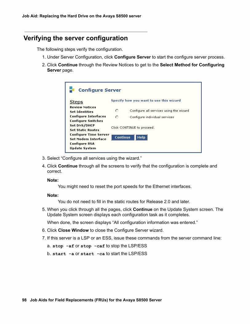
Job Aid: Replacing the Hard Drive on the Avaya S8500 server
98 Job Aids for Field Replacements (FRUs) for the Avaya S8500 Server
Verifying the server configurationThe following steps verify the configuration.
1. Under Server Configuration, click Configure Server to start the configure server process.
2. Click Continue through the Review Notices to get to the Select Method for Configuring Server page.
3. Select “Configure all services using the wizard.”
4. Click Continue through all the screens to verify that the configuration is complete and correct.
Note:Note: You might need to reset the port speeds for the Ethernet interfaces.
Note:Note: You do not need to fill in the static routes for Release 2.0 and later.
5. When you click through all the pages, click Continue on the Update System screen. The Update System screen displays each configuration task as it completes.
When done, the screen displays “All configuration information was entered.”
6. Click Close Window to close the Configure Server wizard.
7. If this server is a LSP or an ESS, issue these commands from the server command line:
a. stop -af or stop -caf to stop the LSP/ESS
b. start -a or start -ca to start the LSP/ESS
03-300529 Issue 4 January 2008 99
Job Aid: Replacing the SAMP on the Avaya S8500 Series server
! Important:Important: Always check the Avaya Support Website for Product Support Notices at http://
support.avaya.com and select Product Support Notices (All Avaya products) in the MOST POPULAR PRODUCTS IN SUPPORT section.
This Job Aid contains the procedures necessary to replace the Server Availability Management Processor™ (SAMP) remote maintenance board on the Avaya S8500C and S8500B servers. Select the appropriate procedure from these links:
l Replacing the SAMP on the Avaya S8500C server
l Replacing the SAMP on the Avaya S8500B server
Replacing the SAMP on the Avaya S8500C serverThe S8500C server (IBM xSeries 306m server) is equipped with the Server Availability Management Processor™ (SAMP) Lite Remote Maintenance Board (RoHS version, Material ID 700405004).
These S8500C SAMP replacement topics are covered in this section:
l Powering down the S8500C server
l Removing the S8500C server from the rack
l Removing the cover of the S8500C server
l Removing and replacing the SAMP card in the S8500C server
l Replacing the cover of the S8500C server
l Reconnecting the cables to the S8500C server
l Powering up the S8500C server
l Reconfiguring the SAMP card on the S8500C server
l S8500C server connections
l S8500C services access and logins

Job Aid: Replacing the SAMP on the Avaya S8500 Series server
100 Job Aids for Field Replacements (FRUs) for the Avaya S8500 Server
Powering down the S8500C server
Note:Note: Wear an antistatic wrist ground strap whenever handling the server or its
components. Connect the strap to an approved ground, such as an unpainted metal surface. See the job aid titled Approved Grounds for more information.
To power down the server:
1. From the Maintenance Web Interface, click Shutdown Server.The Shutdown Server page displays.
2. Select Delayed.
3. Click on the Shutdown button at the bottom of the page.
The Shutdown This Server page displays the shutdown indicators.
4. Wait until the server powers down before proceeding. Since the SAMP has a separate power supply, you must also remove the SAMP power source. Check for the absence of disk activity on the front panel to ensure that the server has powered down.
Removing the S8500C server from the rackTo remove the server:
1. Label and disconnect all cables on the server.
2. Loosen the two front thumbscrews on the server.
3. Carefully pull the server from the rack.
Removing the cover of the S8500C server
! CAUTION:CAUTION: All power must be removed from the server before starting this procedure.
Remember that the SAMP has an independent power source.
ELECTROSTATIC ALERT:ELECTROSTATIC ALERT: Take precautions against electrostatic discharge: wear a wrist strap connected to
an approved ground.

Replacing the SAMP on the Avaya S8500C server
03-300529 Issue 4 January 2008 101
To remove the cover from the S8500C server:
1. Press the release button on the top, left side of the server (see Figure 21: Release button on the S8500C server on page 101).
Figure 21: Release button on the S8500C server
2. Slide the server cover back from the front panel until the cover’s tabs are released from the top slot of the front panel.
3. Lift the cover straight up and set it aside.
Removing and replacing the SAMP card in the S8500C serverThe SAMP card resides in PCI-X slot 1 located under the PCI support bracket. To remove the PCI support bracket and the riser connector in the S8500C server:
1. Loosen the captive screw on the SAMP riser-card assembly as shown in Figure 22.
Figure notes:
1. Cover release button 2. Push cover back and lift straight up.
CD-RW
DVD
1
h3msc85c LAO 032306
2

Job Aid: Replacing the SAMP on the Avaya S8500 Series server
102 Job Aids for Field Replacements (FRUs) for the Avaya S8500 Server
Figure 22: Removing/replacing the SAMP card on the S8500C server
! CAUTION:CAUTION: In the next step, do not pull too hard because the cable assembly is attached to
the SAMP card.
2. Disconnect the cable assembly from the SAMP and from the motherboard (see Figure 22: Removing/replacing the SAMP card on the S8500C server on page 102).
3. Remove the riser-card assembly by holding the narrow (interior) part of the assembly with one hand and the other hand under the support bracket near the captive screw and pulling straight up (see Figure 22: Removing/replacing the SAMP card on the S8500C server on page 102).
Figure notes:
1. Remove cable assembly from SAMP2. Remove riser-card assembly
3. Remove SAMP from riser-card assembly
2
1
Slot 1
Slot 2
2
3
h3mss85c LAO 032306
1
3

Replacing the SAMP on the Avaya S8500C server
03-300529 Issue 4 January 2008 103
4. Remove the old SAMP card from the PCI-X slot 1 by pulling the card gently out of the expansion slot.
5. Carefully grasp the new SAMP by the top edges or upper corners and align it with the PCI-X slot 1 opening on the riser-card assembly. Press the SAMP firmly into the expansion slot.
! CAUTION:CAUTION: Make sure the SAMP card is completely and correctly seated in the expansion
slot before you apply power to the S8500C server. Incomplete insertion might cause damage to the motherboard or to the SAMP card.
6. Replace the cable assembly from the SAMP to the motherboard (see Step 3) with the replacement cable (shipped with the replacement SAMP).
7. Reinstall the riser-card assembly, making sure that
l The riser-card assembly is aligned with the two guides and fully seated in the riser-card connector.
l The ribbon cable is routed so that it is not pinched.
8. Tighten the captive screw on the SAMP riser-card assembly (Figure 22: Removing/replacing the SAMP card on the S8500C server on page 102, note 1).
Replacing the cover of the S8500C serverTo replace the cover on the S8500C server:
1. Replace the cover onto the server.
2. Slide the cover forward so that its tabs slide into place under the top slots of the front panel and the release latches securely (see Figure 21: Release button on the S8500C server on page 101).
3. Slide the server back into place on the data rack.
4. Tighten the two front thumbscrews on the server securely into the rack.
Reconnecting the cables to the S8500C serverAfter the server is replaced and secured in the rack, reconnect the all but the power cable to the server, SAMP, and modem. If you are unsure about the connections, see Figure 24: S8500C server, front view on page 106.

Job Aid: Replacing the SAMP on the Avaya S8500 Series server
104 Job Aids for Field Replacements (FRUs) for the Avaya S8500 Server
Powering up the S8500C serverTo power up the server:
1. Plug the power cord into the power receptacle on the rear of the server.
2. If necessary press the Power button located on the front right-hand side.
3. After the server is up, verify that there is network activity by looking at the network activity LEDs (see Notes 13 or 14 in Figure 25: S8500C server, rear view on page 107).
4. Log into the server after the startup to make sure that the installation is complete.
5. Check the original Ethernet configuration settings by selecting Server Configuration > Configure Server from the Maintenance Web Interface.
6. Confirm that the server’s Ethernet configuration settings are the same as before.
Reconfiguring the SAMP card on the S8500C serverAfter replacing the SAMP card, you might need to update the firmware on the SAMP before you use it. The SAMP comes loaded from the factory with Avaya defaults.
1. Check the Avaya support Website (http://support.avaya.com) for more recent firmware for the SAMP.
! Important:Important: The R2.1 firmware update to the SAMP in the S8500C server is required only on
servers running Communication Manager Release 3.1.2. The R2.1 firmware is not backward -compatible with prior releases of Communication Manager.
2. Download the newer firmware to your laptop.
3. From the Maintenance Web interface, select Miscellaneous > Download Files and press Enter.The Download Files page displays.

Replacing the SAMP on the Avaya S8500C server
03-300529 Issue 4 January 2008 105
Figure 23: Download Files page
4. Select the "File(s) to download from the machine I’m using to connect to the server" button.
5. Use the Browse button to navigate to the firmware file on your laptop.
6. Press the Download button.
7. From the server’s command line type sampupdate and press Enter.8. At the prompt to commit the software and print the software version, respond with Yes.
9. From the server’s command line type convertSampIP (case-sensitive) and press Enter.
Note:Note: Detailed information about configuring the SAMP card is in the Avaya Server
Availability Management Processor User Guide (03-300322).
S8500C server connectionsThis section explains the connections for
l S8500C front panel connections
l S8500C rear panel connections
l S8500C SAMP connections
l S8500C network interface card connections
l S8500C modem connections

Job Aid: Replacing the SAMP on the Avaya S8500 Series server
106 Job Aids for Field Replacements (FRUs) for the Avaya S8500 Server
S8500C front panel connections
Figure 24 shows the connections that are available on the front panel of the S8500C server.
Figure 24: S8500C server, front view
Figure notes:
1. Power-on LED1
2. Power button2
3. Reset button4. Hard disk drive activity LED5. Locator LED3
6. System error LED1. If this LED is off, it does not mean that there is no electrical power in the server. To remove all electrical
power from the server, you must disconnect the power cord from the electrical outlet.
2. A shield is installed around the button to prevent powering down the server accidentally. You can remove this disk-shaped shield if you prefer.
3. This LED can be remotely lit to aid in visually locating the server.
7. USB port8. USB port9. Hard disk drive
10. CD eject button11. CD drive activity LED
h3msf8cc LAO 031706
CD-RWDVD
712
34
56 8
9
10 11

Replacing the SAMP on the Avaya S8500C server
03-300529 Issue 4 January 2008 107
S8500C rear panel connections
Figure 25 shows the connections that are available on the rear panel of the S8500C server.
Figure 25: S8500C server, rear view
S8500C SAMP connections
The SAMP also communicates with the host in-band through an onboard, industry-standard Ethernet controller on the host’s PCI bus with an internal link to the SAMP as shown in Figure 26: S8500C and SAMP connections and network interfaces on page 108.
Figure notes:
1. Power cord connector2. SAMP power3. USB connection (to USB modem)4. Ethernet (not used)5. SAMP services port6. SAMP card7. Dual NIC8. Ethernet 49. Ethernet 3
10. Mouse connector11. USB port12. USB port13. Ethernet 114. Ethernet 215. Video connector16. Serial connector17. Keyboard connector
h2msb8cc LAO 031706
2
1
Slot 1Slot 2
712
34
56 8
910
1112
1314 16
1715

Job Aid: Replacing the SAMP on the Avaya S8500 Series server
108 Job Aids for Field Replacements (FRUs) for the Avaya S8500 Server
Figure 26: S8500C and SAMP connections and network interfaces
The SAMP card is a half-card PCI form factor that is powered externally. It supports one USB interface and two 10/100 Ethernet ports that are located on the rear of the server.
l SAMP Ethernet 1 is not used.
l SAMP Ethernet 2 is for local Services laptop access. This is for on-site services personnel (or customer) to access the SAMP using the craft login.
l The USB interface (acm0) connects a USB modem for remote dial-in/dial-out access. This modem connection is shared between the server and the SAMP for remote maintenance, administration, and alarming. For dial-in purposes, the user first establishes a ppp session that terminates at the SAMP. The user then can establish an SSH (Secure Shell) or HTTPS (Secure Web) session to the SAMP or the host using the craft login.
Figure notes:
1. SAMP Eth0 interface (192.11.13.2) 2. S8500C Ethx interface (192.11.13.1)
Host(S8500B)
Externalcompact flash
cydssamp KLC 101204
Customer LANaccess/control network
InternalSAMP-HOST link
IP address:192.11.13.6Type: Static
Services laptopIP address: 192.11.13.6
Services laptopIP address:192.11.13.5Type: Static
ModemIP address: 10.1.2.3Type: Static
SAMP
Dual NIC(optional)
USBeth0
eth1
eth1
eth2
eth0
ethx
acm0
Reserved(Services forfuture use)
INADS serverIP: 10.1.2.2Type: Static
1
2
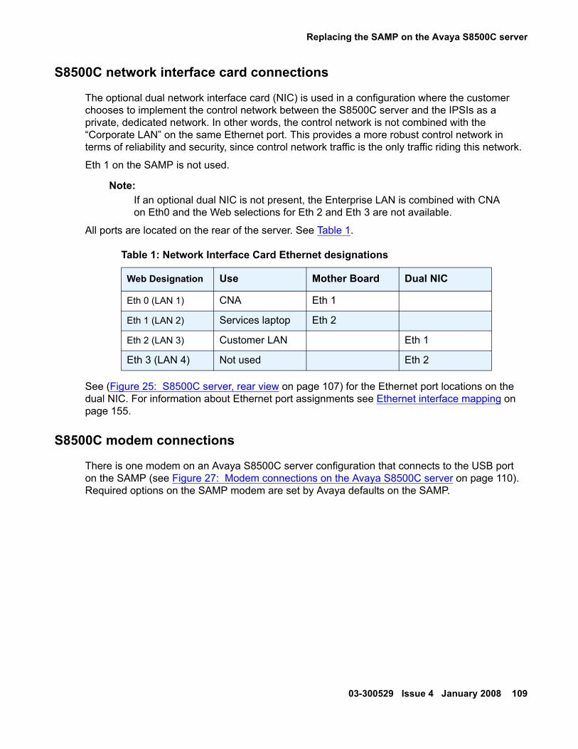
Replacing the SAMP on the Avaya S8500C server
03-300529 Issue 4 January 2008 109
S8500C network interface card connections
The optional dual network interface card (NIC) is used in a configuration where the customer chooses to implement the control network between the S8500C server and the IPSIs as a private, dedicated network. In other words, the control network is not combined with the “Corporate LAN” on the same Ethernet port. This provides a more robust control network in terms of reliability and security, since control network traffic is the only traffic riding this network.
Eth 1 on the SAMP is not used.
Note:Note: If an optional dual NIC is not present, the Enterprise LAN is combined with CNA
on Eth0 and the Web selections for Eth 2 and Eth 3 are not available.
All ports are located on the rear of the server. See Table 1.
See (Figure 25: S8500C server, rear view on page 107) for the Ethernet port locations on the dual NIC. For information about Ethernet port assignments see Ethernet interface mapping on page 155.
S8500C modem connections
There is one modem on an Avaya S8500C server configuration that connects to the USB port on the SAMP (see Figure 27: Modem connections on the Avaya S8500C server on page 110). Required options on the SAMP modem are set by Avaya defaults on the SAMP.
Table 1: Network Interface Card Ethernet designations
Web Designation Use Mother Board Dual NIC
Eth 0 (LAN 1) CNA Eth 1
Eth 1 (LAN 2) Services laptop Eth 2
Eth 2 (LAN 3) Customer LAN Eth 1
Eth 3 (LAN 4) Not used Eth 2
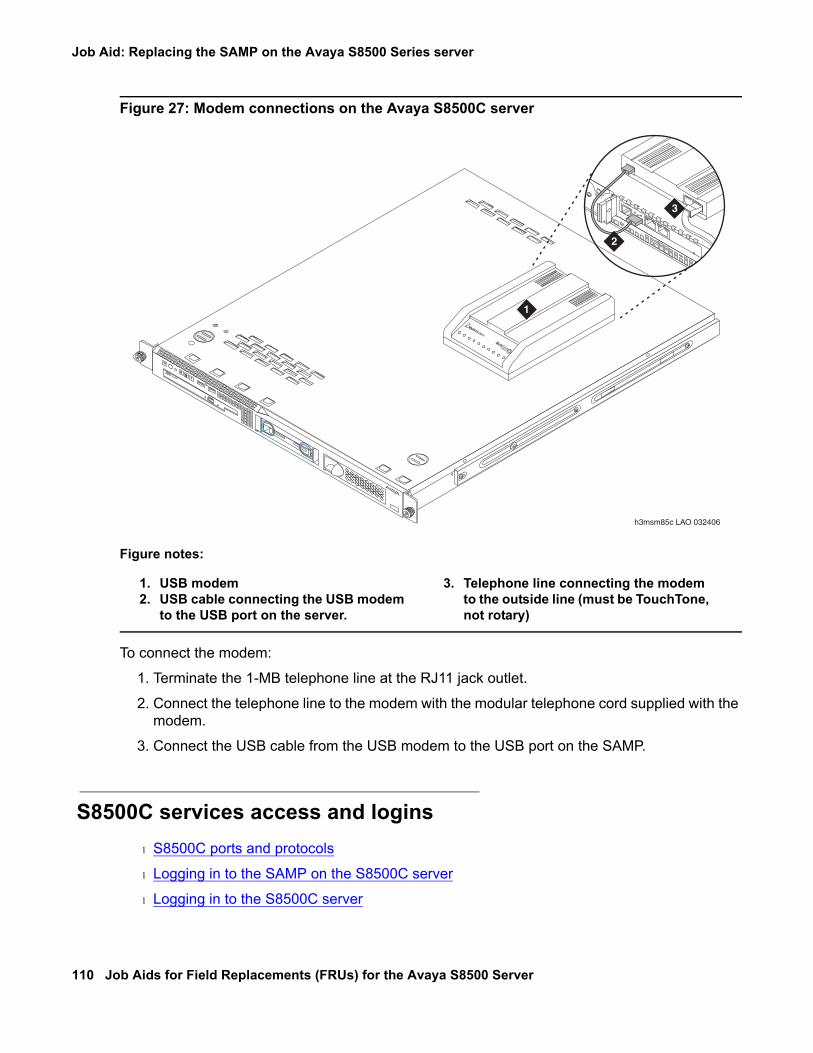
Job Aid: Replacing the SAMP on the Avaya S8500 Series server
110 Job Aids for Field Replacements (FRUs) for the Avaya S8500 Server
Figure 27: Modem connections on the Avaya S8500C server
To connect the modem:
1. Terminate the 1-MB telephone line at the RJ11 jack outlet.
2. Connect the telephone line to the modem with the modular telephone cord supplied with the modem.
3. Connect the USB cable from the USB modem to the USB port on the SAMP.
S8500C services access and loginsl S8500C ports and protocols
l Logging in to the SAMP on the S8500C server
l Logging in to the S8500C server
Figure notes:
1. USB modem2. USB cable connecting the USB modem
to the USB port on the server.
3. Telephone line connecting the modem to the outside line (must be TouchTone, not rotary)
CD-RW
DVD
h3msm85c LAO 032406
MultiModem
MultiTechSoftware
1
Slot 1
3
2

Replacing the SAMP on the Avaya S8500C server
03-300529 Issue 4 January 2008 111
S8500C ports and protocols
Table 2 lists all the services access protocols available on the SAMP services laptop port.
Table 3 lists all the services access protocols available on the SAMP services laptop port.
Table 2: Services access to the SAMP
Access Method Service Requested TCP Port Service Granted
Services laptop SSH 10022 Secure Shell access to SAMP
Services laptop HTTPS 10443 Secure Web access to SAMP
Services laptop SSH 22 Secure Shell access to host
Services laptop HTTPS 443 Secure Web access to host
Services laptop Telnet 23 Shell access to host
Services laptop Telnet 5023 Access to SAT on host
Modem dial-in ppp->SSH 10022 Secure Shell access to SAMP
Modem dial-in ppp->HTTPS 10443 Secure Web access to SAMP
Modem dial-in ppp->SSH 22 Secure Shell access to host
Modem dial-in ppp->HTTPS 443 Secure Web access to host
Modem dial-in ppp->Telnet 23 Shell access to host
Modem dial-in ppp->Telnet 5023 Access to SAT on host
Modem dial-in ppp->SSH 5022 Secure access to SAT on host
Table 3: Services laptop access on the host
Access Method Service Requested TCP Port Service Granted
Services laptop SSH 22 Secure Shell access to host
Services laptop HTTPS 443 Secure Web access to host
Services laptop Telnet 23 Shell access to host
Services laptop Telnet 5023 Access to SAT on host

Job Aid: Replacing the SAMP on the Avaya S8500 Series server
112 Job Aids for Field Replacements (FRUs) for the Avaya S8500 Server
Logging in to the SAMP on the S8500C server
There are two ways to log in to the SAMP:
l Logging directly into the SAMP
l Logging into the SAMP through the modem
Logging directly into the SAMP - To log directly in to the SAMP:
1. SSH (TCP Port 10022) or HTTPS (TCP Port 10443) to IP address 192.11.13.6.
For SSH, type ssh -p10022 192.11.13.6 and press Enter to get to the SAMP login.
For HTTPS, in the web URL, type 192.11.13.6:10443 (the IP address and port of the SAMP Web pages) and press Enter.
2. Log in to the system using the craft login.
Logging into the SAMP through the modem - To log in to the SAMP through the modem:
1. Set up a ppp session by dialing into the modem.
Use the rasaccess or the customer-created login for ppp authentication.
2. SSH (TCP Port 10022) or HTTPS (TCP Port 10443) to the modem IP address (for example, 10.0.2.2). Examples:
l For SSH type ssh -p10022 ipaddress and press Enter to get to the SAMP login.
l For HTTPS type ipaddress:10443 (the IP address and port of the SAMP Web pages) and press Enter.
The log in screen displays.

Replacing the SAMP on the Avaya S8500C server
03-300529 Issue 4 January 2008 113
3. Log in to the system using the craft login.
The SAMP home page displays.
Logging in to the S8500C server
To log in to the server:
1. Set up a ppp session by dialing into the modem.
Use the rasaccess login for ppp authentication.
2. SSH (TCP Port 22) or HTTPS (TCP Port 443) to the modem IP address (for example, 10.1.2.3).
For SSH type ssh 10022 10.1.2.3 and press Enter to get to the SAMP login.
For HTTPS type 10.1.2.3 (the IP address of the SAMP Web pages) and press Enter.3. Log in to the system using the craft login.
4. At the ASG challenge, type the password and press Enter.

Job Aid: Replacing the SAMP on the Avaya S8500 Series server
114 Job Aids for Field Replacements (FRUs) for the Avaya S8500 Server
Replacing the SAMP on the Avaya S8500B serverThe S8500B server (IBM x306 server) is equipped with the Server Availability Management Processor™ (SAMP) remote maintenance board (Material ID 700330814).
These S8500B SAMP replacement topics are covered in this section:
l Powering down the S8500B server
l Removing the S8500B server from the rack
l Removing the cover of the S8500B server
l Removing and replacing the SAMP card on the S8500B server
l Replacing the cover of the S8500B server
l Reconnecting cables on the S8500B server
l Powering up the S8500B server
l Reconfiguring the SAMP card on the S8500B server
l S8500B server connections
l S8500B services access and logins
Powering down the S8500B server
Note:Note: Wear an antistatic wrist ground strap whenever handling the server or its
components. Connect the strap to an approved ground, such as an unpainted metal surface. See the job aid titled Approved Grounds for more information.
To power down the S8500B server:
1. From the Maintenance Web Interface, click Shutdown Server.The Shutdown Server page displays.
2. Select Delayed.
3. Click on the Shutdown button at the bottom of the page.
The Shutdown This Server page displays the shutdown indicators.
4. Wait until the server powers down before proceeding. Check for the absence of disk activity on the front panel to determine whether the server has powered down.

Replacing the SAMP on the Avaya S8500B server
03-300529 Issue 4 January 2008 115
Removing the S8500B server from the rackTo remove the S8500B server from its rack:
1. Label and disconnect all cables on the server.
2. Loosen the two front thumbscrews on the server.
3. Carefully pull the server from the rack.
Removing the cover of the S8500B server
! CAUTION:CAUTION: All power must be removed from the server before starting this procedure.
ELECTROSTATIC ALERT:ELECTROSTATIC ALERT: Take precautions against electrostatic discharge: wear a wrist strap connected to
an approved ground.
To remove the cover from the S8500B server:
1. Loosen the captive screw on the rear center of the server (see Figure 28: Locating the server cover’s captive screw on page 115).
Figure 28: Locating the server cover’s captive screw
Figure notes:
1. server cover’s captive screw
h3dscapb KLC 093004
1

Job Aid: Replacing the SAMP on the Avaya S8500 Series server
116 Job Aids for Field Replacements (FRUs) for the Avaya S8500 Server
2. Slide the server cover back from the front panel until the cover’s tabs are released from the top slot of the front panel.
3. Lift the cover straight up and move it away from the server.
Removing and replacing the SAMP card on the S8500B serverThe SAMP card resides in PCI-X slot 1 located under the PCI support bracket. To remove the PCI support bracket and the riser connector:
1. Loosen the captive screw on the SAMP riser-card assembly as shown in Figure 29: Removing/replacing the SAMP card on the S8500B server on page 117.

Replacing the SAMP on the Avaya S8500B server
03-300529 Issue 4 January 2008 117
Figure 29: Removing/replacing the SAMP card on the S8500B server
Figure notes:
1. Loosen captive screw on SAMP2. Remove riser-card assembly
3. Remove cable assembly from SAMP
2
1
2
2
1
1
3
indssamp KLC 101504

Job Aid: Replacing the SAMP on the Avaya S8500 Series server
118 Job Aids for Field Replacements (FRUs) for the Avaya S8500 Server
! CAUTION:CAUTION: In the next step, do not pull too hard because the cable assembly is attached to
the SAMP card.
2. Remove the riser-card assembly by holding the narrow (interior) part of the assembly with one hand and the other hand under the support bracket near the captive screw and pulling straight up (see Figure 29: Removing/replacing the SAMP card on the S8500B server on page 117).
3. Disconnect the cable assembly from the SAMP and from the motherboard (see Figure 29: Removing/replacing the SAMP card on the S8500B server on page 117).
4. Remove the old SAMP card from the PCI-X slot 1 by pulling the card gently out of the expansion slot.
5. Carefully grasp the new SAMP by the top edges or upper corners and align it with the PCI-X slot 1 opening on the riser-card assembly. Press the SAMP firmly into the expansion slot.
! CAUTION:CAUTION: Make sure the SAMP card is completely and correctly seated in the expansion
slot before you apply power to the S8500B server. Incomplete insertion might cause damage to the system board or to the SAMP card.
6. Replace the cable assembly from the SAMP to the motherboard (see Step 3) with the replacement cable (shipped with the replacement SAMP).
7. Reinstall the riser-card assembly, making sure that
l The riser-card assembly is aligned with the two guides and fully seated in the riser-card connector.
l The ribbon cable is routed so that it is not pinched.
8. Tighten the captive screw on the SAMP riser-card assembly (Figure 29: Removing/replacing the SAMP card on the S8500B server on page 117, note 1).
Replacing the cover of the S8500B serverTo replace the cover on the S8500B server:
1. Replace the cover onto the server.
2. Slide the cover forward so that its tabs slide into place under the top slots of the front panel.
3. Finger-tighten the thumbscrew on the rear center of the server (see Figure 28: Locating the server cover’s captive screw on page 115).
4. Slide the server back into place on the data rack.
5. Tighten the two front thumbscrews on the server securely into the rack.

Replacing the SAMP on the Avaya S8500B server
03-300529 Issue 4 January 2008 119
Reconnecting cables on the S8500B serverAfter the server is replaced and secured in the rack, reconnect the all but the power cable to the server, SAMP, and modem. If you are unsure about the connections, see S8500B server connections on page 121.
Powering up the S8500B serverTo power up the server:
1. Plug the power cord into the power receptacle on the rear of the server.
2. If necessary press the Power button located on the front right-hand side.
3. Verify that there is network activity by looking at the network activity LEDs (see Figure 30).
Figure 30: S8500B server rear panel network activity LEDs
4. Log into the server after the startup to make sure that the installation is complete.
5. Check the original Ethernet configuration settings by selecting Server Configuration > Configure Server from the Maintenance Web Interface.
6. Confirm that the server’s Ethernet configuration settings are the same as before.
Figure notes:
1. Network activity LED (Tx/Rx) 2. Connection rate:l Off: a 10BASE-T active linkl Green: a 100BASE-T active linkl Orange: a 1000BASE-T active link
2
h3msble7 KLC 110104
1
1
22

Job Aid: Replacing the SAMP on the Avaya S8500 Series server
120 Job Aids for Field Replacements (FRUs) for the Avaya S8500 Server
Reconfiguring the SAMP card on the S8500B serverAfter replacing the SAMP card, you must configure the SAMP before you use it. To reconfigure the SAMP card on the S8500B server:
1. Check the Avaya support Website (http://support.avaya.com) for updated firmware (called R2) for the SAMP.
! Important:Important: The R2 firmware update to the SAMP in the S8500B server is required only on
servers running Communication Manager Release 3.1. The R2 firmware is not backward -compatible with prior releases of Communication Manager.
2. Download the firmware to your laptop.
3. From the Maintenance Web interface, select Miscellaneous > Download Files and press Enter.The Download Files page displays.
Figure 31: Download Files page
4. Select the "File(s) to download from the machine I’m using to connect to the server" button.
5. Use the Browse button to navigate to the firmware file on your laptop.
6. Press the Download button.
7. From the server’s command line type sampupdate and press Enter.

Replacing the SAMP on the Avaya S8500B server
03-300529 Issue 4 January 2008 121
8. At the prompt to commit the software and print the software version, respond with Yes.
9. From the server’s command line type convertSampIP (case-sensitive) and press Enter.
Note:Note: Detailed information about configuring the SAMP card is in the Avaya Server
Availability Management Processor User Guide (03-300322).
S8500B server connectionsThis section explains the S8500B server connections:
l S8500B front panel connections
l S8500B rear panel connections
l S8500B SAMP connections
l S8500B network interface card connections
l S8500B modem connections

Job Aid: Replacing the SAMP on the Avaya S8500 Series server
122 Job Aids for Field Replacements (FRUs) for the Avaya S8500 Server
S8500B front panel connections
Figure 32: S8500B server, front view on page 122 shows the connections that are available on the front panel of the S8500B server.
Figure 32: S8500B server, front view
Figure notes:
1. CD-ROM drive activity LED2. CD eject button3. CD-ROM drive activity LED4. CD-ROM eject button5. System error LED6. System locator LED (blue); use to
visually locate the server if it is in a location with other servers.
7. Hard disk drive activity LED
8. Power on LEDl Lit (not flashing): the server is on.l Flashing: the server is turned off and still
connected to an AC power source.l Off: AC power is not present, or the power
supply or the LED itself has failed.9. Power control button
10. Reset button: press to reset the server and run the power-on self-test (POST). You might have to use a pen or the end of a straightened paper clip to press the button.
11. USB connections for the Compact Flash
8
9
1011
21 4 5 6 73
h2ms85bf KLC 091704

Replacing the SAMP on the Avaya S8500B server
03-300529 Issue 4 January 2008 123
S8500B rear panel connections
Figure 33: S8500B server, rear view on page 123 shows the connections that are available on the rear panel of the S8500B server.
Figure 33: S8500B server, rear view
Connection to the customer’s network is through port 1 (Eth0) on the rear of the Avaya S8500B server, using a standard CAT5 cable with RJ45 connectors on each end. The other end of the cable connects to an Ethernet switch (router) or hub.
If the S8500B server has only one port network, connect it through the dual NIC. See Figure 34: CAT5 cables connected to a port on the rear of the Avaya S8500B server on page 124 for connectivity information.
Figure notes:
1. Power connector2. Keyboard connector3. Mouse connector4. LAN 1 transmit/receive activity LED
(on Ethernet connector). When lit, it indicates that there is activity between the server and the network.
5. LAN 1 speed 1 Gbps LED (on Ethernet connector). When lit, it indicates that the Ethernet network speed is 1 Gbps; when off, it indicates that the Ethernet network speed is 10 Mbps or 100 Mbps.
6. Dual NIC (optional)
7. Server Availability Management Processor (SAMP)
8. LAN 2 speed 1 Gbps LED (on Ethernet connector). When lit, it indicates that the Ethernet network speed is 1 Gbps; when off, it indicates that the Ethernet network speed is 10 Mbps or 100 Mbps.
9. LAN 2 transmit/receive activity LED (on Ethernet connector). When lit, it indicates that there is activity between the server and the network.
10. USB connectors11. Video connector12. RS-232 serial interface
h2ms85bb KLC 091704
2
2
89101112
1 3 4 5 6 7

Job Aid: Replacing the SAMP on the Avaya S8500 Series server
124 Job Aids for Field Replacements (FRUs) for the Avaya S8500 Server
Figure 34: CAT5 cables connected to a port on the rear of the Avaya S8500B server
The SAMP also communicates with the host in-band through an onboard, industry-standard Ethernet controller on the host’s PCI bus with an internal link to the SAMP as shown in Figure 35: S8500B and SAMP connections and network interfaces on page 125.
Figure notes:
1. Eth0 — to customer’s network if nondedicated control network (straight-through CAT5 cable)
2. Eth1 — to services laptop (cross-connect CAT5 cable)
3. Eth2 — to port network if only one port network (cross-connect CAT5 cable) or to customer’s network if dedicated control network (straight-through CAT5 cable)
4. Eth3 — not used
2
1
2
h3msbl5a KLC 093004
1
4
2
3
1

Replacing the SAMP on the Avaya S8500B server
03-300529 Issue 4 January 2008 125
Figure 35: S8500B and SAMP connections and network interfaces
S8500B SAMP connections
The SAMP card comes in a half card PCI form factor and is powered externally. It supports one USB interface and two 10/100 Ethernet ports that are located on the rear of the server.
l SAMP Ethernet 1 is not used.
l SAMP Ethernet 2 is for local Services laptop access. This is for on-site services personnel (or customer) to access the SAMP using the craft login.
l The USB interface is used to connect a USB modem that is used for remote dial-in and dial-out access. This modem connection is shared between the server and the SAMP for remote maintenance, administration, and alarming purposes. For dial-in purposes, the user first establishes a ppp session that terminates at the SAMP. The user then can establish an SSH (Secure Shell) or HTTPS (Secure Web) session to the SAMP or the host using the craft login.
See (Figure 36) for SAMP connections (Notes 5-8).
Figure notes:
1. SAMP Eth0 interface (192.11.13.2) 2. S8500B Ethx interface (192.11.13.1)
Host(S8500B)
Externalcompact flash
cydssamp KLC 101204
Customer LANaccess/control network
InternalSAMP-HOST link
IP address:192.11.13.6Type: Static
Services laptopIP address: 192.11.13.6
Services laptopIP address:192.11.13.5Type: Static
ModemIP address: 10.1.2.3Type: Static
SAMP
Dual NIC(optional)
USBeth0
eth1
eth1
eth2
eth0
ethx
acm0
Reserved(Services forfuture use)
INADS serverIP: 10.1.2.2Type: Static
1
2

Job Aid: Replacing the SAMP on the Avaya S8500 Series server
126 Job Aids for Field Replacements (FRUs) for the Avaya S8500 Server
Figure 36: Server Availability Management Processor rear connections
S8500B network interface card connections
The optional dual network interface card (NIC) is used in a configuration where the customer chooses to implement the control network between the S8500B server and the IPSIs as a private, dedicated network. In other words, the control network is not combined with the “Corporate LAN” on the same Ethernet port. This provides a more robust control network in terms of reliability and security, since control network traffic is the only traffic riding this network.
Eth 1 on the SAMP is not used.
Note:Note: If an optional dual NIC is not present, the Enterprise LAN is combined with CNA
on Eth0 and the web selections for Eth 2 and Eth 3 are not available.
Figure notes:
1. Mouse connector (not used)2. Connection to customer’s network in
nondedicated control network, or direct connection to gateway IPSI in dedicated control network
3. Optional dual network interface card (NIC)
4. Optional dual network interface card (NIC)
5. Connection to services laptop for Server Availability Management Processor (SAMP)
6. Eth 1 on SAMP (not used)7. SAMP USB modem port8. SAMP power supply9. Connection to services laptop
10. Additional USB ports 11. Video port (not used)12. RS-232 serial interface — can be used for
console redirection to perform BIOS upgrades
13. Keyboard connector (not used)
2
h2ms85b2 LAO 101204
910111213
71 2 3 4 5 6 8

Replacing the SAMP on the Avaya S8500B server
03-300529 Issue 4 January 2008 127
All ports are located on the rear of the server. See Table 4.
See (Figure 37: S8500 B network interface card connections on page 127) for the Ethernet port locations on the NIC.
Figure 37: S8500 B network interface card connections
For more information see Ethernet interface mapping on page 155.
S8500B modem connections
There is one modem on an Avaya S8500B server configuration that connects to the USB port on the SAMP (see Figure 38: Modem connections on the Avaya S8500B server on page 128). Required options on the SAMP modem are set by Avaya defaults on the SAMP.
Table 4: Network Interface Card Ethernet designations
Web Designation Use Mother Board Dual NIC
Eth 0 (LAN 1) CNA Eth 1
Eth 1 (LAN 2) Services laptop Eth 2
Eth 2 (LAN 3) Customer LAN Eth 1
Eth 3 (LAN 4) Not used Eth 2
Figure notes:
1. LAN 3 - to customer LAN 2. LAN 4 - not used
h2ms85b1 KLC 100504
2
1 2

Job Aid: Replacing the SAMP on the Avaya S8500 Series server
128 Job Aids for Field Replacements (FRUs) for the Avaya S8500 Server
Figure 38: Modem connections on the Avaya S8500B server
To connect the modem:
1. Terminate the 1-MB telephone line at the RJ11 jack outlet.
2. Connect the telephone line to the modem with the modular telephone cord supplied with the modem.
3. Connect the USB cable from the USB modem to the USB port on the SAMP.
Figure notes:
1. Modem2. USB cable connecting the USB
modem to the USB port on the server.
3. Telephone line connecting the modem to the outside line (must be TouchTone, not rotary)
h3msm85b KLC 093004
disc
MultiModem
MultiTechSoftware
1
3
2

Replacing the SAMP on the Avaya S8500B server
03-300529 Issue 4 January 2008 129
S8500B services access and loginsl S8500B ports and protocols
l Services laptop access to the SAMP on the S8500B server
l Logging in to the S8500B SAMP
l Logging in to the S8500B server
S8500B ports and protocols
Table 5 lists all the services access protocols available on the SAMP services laptop port.
Table 5: Services access to the SAMP
Access Method Service Requested TCP Port Service Granted
Services laptop SSH 10022 Secure Shell access to SAMP
Services laptop HTTPS 10443 Secure Web access to SAMP
Services laptop SSH 22 Secure Shell access to host
Services laptop HTTPS 443 Secure Web access to host
Services laptop Telnet 23 Shell access to host
Services laptop Telnet 5023 Access to SAT on host
Modem dial-in ppp->SSH 10022 Secure Shell access to SAMP
Modem dial-in ppp->HTTPS 10443 Secure Web access to SAMP
Modem dial-in ppp->SSH 22 Secure Shell access to host
Modem dial-in ppp->HTTPS 443 Secure Web access to host
Modem dial-in ppp->Telnet 23 Shell access to host
Modem dial-in ppp->Telnet 5023 Access to SAT on host
Modem dial-in ppp->SSH 5022 Secure access to SAT on host

Job Aid: Replacing the SAMP on the Avaya S8500 Series server
130 Job Aids for Field Replacements (FRUs) for the Avaya S8500 Server
Table 6 lists all the services access protocols available on the SAMP services laptop port.
Services laptop access to the SAMP on the S8500B server
The SAMP has a dedicated services laptop access for on-site maintenance and administration purposes (Eth2) as shown in Figure 39: Services laptop computer connected directly to the S8500B server on page 131. The IP address is 192.11.13.6.
Table 6: Services laptop access on the host
Access Method Service Requested TCP Port Service Granted
Services laptop SSH 22 Secure Shell access to host
Services laptop HTTPS 443 Secure Web access to host
Services laptop Telnet 23 Shell access to host
Services laptop Telnet 5023 Access to SAT on host
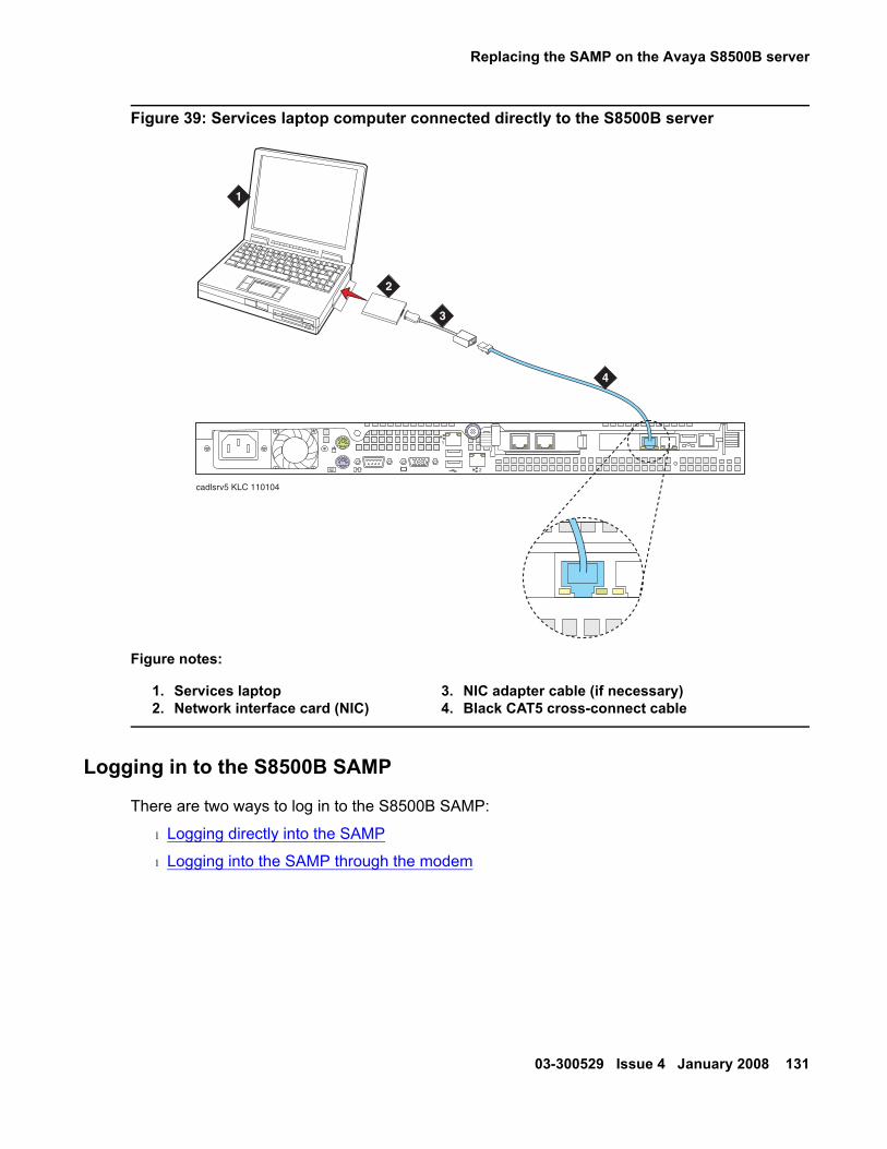
Replacing the SAMP on the Avaya S8500B server
03-300529 Issue 4 January 2008 131
Figure 39: Services laptop computer connected directly to the S8500B server
Logging in to the S8500B SAMP
There are two ways to log in to the S8500B SAMP:
l Logging directly into the SAMP
l Logging into the SAMP through the modem
Figure notes:
1. Services laptop2. Network interface card (NIC)
3. NIC adapter cable (if necessary)4. Black CAT5 cross-connect cable
2
1
cadlsrv5 KLC 110104
1
2
3
4

Job Aid: Replacing the SAMP on the Avaya S8500 Series server
132 Job Aids for Field Replacements (FRUs) for the Avaya S8500 Server
Logging directly into the SAMP - To log directly in to the SAMP:
1. SSH (TCP Port 10022) or HTTPS (TCP Port 10443) to IP address 192.11.13.6.
For SSH, type ssh -p10022 192.11.13.6 and press Enter to get to the SAMP login.
For HTTPS, in the web URL, type 192.11.13.6:10443 (the IP address and port of the SAMP Web pages) and press Enter.
2. Log in to the system using the craft login.
Logging into the SAMP through the modem - To log in to the SAMP through the modem:
1. Set up a ppp session by dialing into the modem.
Use the rasaccess or the customer-created login for ppp authentication.
2. SSH (TCP Port 10022) or HTTPS (TCP Port 10443) to the modem IP address (for example, 10.0.2.2). Examples:
l For SSH type ssh -p10022 ipaddress and press Enter to get to the SAMP login.
l For HTTPS type ipaddress:10443 (the IP address and port of the SAMP Web pages) and press Enter.
The log in screen displays.

Replacing the SAMP on the Avaya S8500B server
03-300529 Issue 4 January 2008 133
3. Log in to the system using the craft login.
The SAMP home page displays.
Logging in to the S8500B server
To log in to the S8500B server:
1. Set up a ppp session by dialing into the modem.
Use the rasaccess login for ppp authentication.
2. SSH (TCP Port 22) or HTTPS (TCP Port 443) to the modem IP address (for example, 10.1.2.3).
For SSH type ssh 10022 10.1.2.3 and press Enter to get to the SAMP login.
For HTTPS type 10.1.2.3 (the IP address of the SAMP Web pages) and press Enter.3. Log in to the system using the craft login.
4. At the ASG challenge, type the password and press Enter.

Job Aid: Replacing the SAMP on the Avaya S8500 Series server
134 Job Aids for Field Replacements (FRUs) for the Avaya S8500 Server
03-300529 Issue 4 January 2008 135
Job Aid: Replacing the SAMP power supply
! Important:Important: Always check the Avaya Support Website for Product Support Notices at
http://support.avaya.com and select Product Support Notices (All Avaya products) in the MOST POPULAR PRODUCTS IN SUPPORT section.
This Job Aid contains two replacement procedures:
l Replacing the SAMP power supply on the S8500C server
l Replacing the SAMP power supply on the S8500B server
! Important:Important: Ensure that you have the proper replacement power supply for the SAMP. The
replacement parts are not interchangeable.
Replacing the SAMP power supply on the S8500C serverThis simple procedure requires two steps:
l Removing the old power supply from the S8500B
l Replacing the power supply from the S8500B
! Important:Important: Ensure that the replacement power supply is Material ID 700405004 (RoHS
version) only. You cannot interchange SAMP power supplies.
Removing the old SAMP power supply from the S8500CTo remove the old or defective SAMP power supply from the S8500C server you do not need to power-down the server:
1. Remove the plug from the power source.
2. Remove the power connection from the SAMP board’s RJ11 connector on the rear panel of the S8500C server.
3. Do not re-use any part of the power supply.

Job Aid: Replacing the SAMP power supply
136 Job Aids for Field Replacements (FRUs) for the Avaya S8500 Server
Replacing the SAMP power supply from the S8500CTo replace the SAMP power supply (RoHS version, Material ID 700405004):
1. Connect the RJ11 end of the new power supply to the connector on the rear panel of the S8500B server.
2. Connect the grounded, 110 VAC plug to the new transformer.
3. Connect the plug to the power source.
Replacing the SAMP power supply on the S8500B serverThis simple procedure requires two steps:
l Removing the old power supply from the S8500B
l Replacing the power supply from the S8500B
! Important:Important: Ensure that the replacement power supply is Material ID 700340110 only. You
cannot interchange SAMP power supplies.
Removing the old power supply from the S8500BTo remove the old or defective SAMP power supply from the S8500B server you do not need to power-down the server:
1. Remove the plug from the power source.
2. Remove the power connection from the SAMP board’s RJ11 connector on the rear panel of the S8500B server.
3. Do not re-use any part of the power supply.

Replacing the SAMP power supply on the S8500B server
03-300529 Issue 4 January 2008 137
Replacing the power supply from the S8500BTo replace the SAMP power supply (Material ID 700340110) on the S8500B server:
1. Connect the RJ11 end of the new power supply to the connector on the rear panel of the S8500B server.
2. Connect the grounded, 110 VAC plug to the new transformer.
3. Connect the plug to the power source.

Job Aid: Replacing the SAMP power supply
138 Job Aids for Field Replacements (FRUs) for the Avaya S8500 Server

03-300529 Issue 4 January 2008 139
Job Aid: Replacing the Avaya S8500 dual network interface
! Important:Important: Always check the Avaya Support Website for Product Support Notices at
http://support.avaya.com and select Product Support Notices (All Avaya products) in the MOST POPULAR PRODUCTS IN SUPPORT section.
This document describes the steps required to replace an existing dual network interface card:
l S8500 and S8500B servers use Material ID 700284623
l S8500C servers use Material ID 700406725
The components of this procedure include:
l Check Ethernet interface settings
l Backing up the server
l Powering down the server
l Removing the cover of the server
l Removing the fan unit (S8500 only)
l Removing the old network interface card
l Installing the new network interface card
l Replacing the fan unit (S8500 only)
l Replacing the cover and cabling
l Powering up the server
l Checking LED activity on the dual network interface card
l Configuring the NIC
! CAUTION:CAUTION: Wear an antistatic wrist ground strap whenever handling the server or its
components. Connect the strap to an approved ground, such as an unpainted metal surface.

Job Aid: Replacing the Avaya S8500 dual network interface
140 Job Aids for Field Replacements (FRUs) for the Avaya S8500 Server
Check Ethernet interface settingsBefore replacing the dual network interface, write down the Ethernet interface settings:
1. Go to Server Configuration > Configure Server Web page.
2. Click Continue through the review notices until you get to the Configure Server page with "Specify how you want to use this wizard" at the top.
3. Select Configure Individual Services and click Continue.
The wizard displays a new left-side navigation panel.
4. Select Set Identities.
The Set Server Identities page displays.
5. Write down the Ethernet interface settings. You will use them again at Configuring the NIC on page 154.

Backing up the server
03-300529 Issue 4 January 2008 141
Backing up the serverNote:
Note: When replacing the dual NIC in an S8500/B/C server functioning as the Secure Services Gateway (SSG) for a Secure Access and Control (SAC) deployment, back up the SSG configuration. For information on how to backup the SSG configuration, see Secure Services Gateway (SSG) Maintenance Guide, 9-300174. Backing up the server is not applicable for the SSG.
Backup the S8500/B/C server before you power it down. To backup the server complete the following steps:
1. Connect the services laptop to the port labeled 2 (Eth 1) on the back of the server using the crossover cable.
2. Open a browser window on the laptop.
3. In the address field of the browser, type in the URL for the server and press Enter.A welcome window displays.
4. Click Continue.
5. Accept the Avaya certificate by clicking Yes.
The logon window displays.
6. Type craft in the Logon ID field and the password (obtained from ART) in the Password field and click Logon.
7. Suppress alarm origination by clicking Yes.
8. Click Launch Maintenance Web Interface.
9. Select Data Backup/Restore > Backup Now from the navigation pane.
10. Select Server and System Files, Security Files, Avaya Call Processing (ACP Translations under the Data Sets heading.
11. Select one of the following backup methods:
l FTP
l Local PC card
12. If you want to encrypt the backup, select the Encrypt backup using pass phrase check box and type a pass phrase.
13. Click Start Backup.

Job Aid: Replacing the Avaya S8500 dual network interface
142 Job Aids for Field Replacements (FRUs) for the Avaya S8500 Server
Powering down the serverAfter the backup is finished, complete the following steps to power down the S8500/B/C server.
1. From the server Web interface click Shutdown This Server; select Delayed.
2. After the server shuts down unplug the power cord from the back of the server.
3. Label and disconnect the Ethernet cable from the chassis.
4. Label and disconnect the power cord from the SAMP.
5. Label and disconnect the USB modem cable from the RS-232 port on the SAMP.
6. Label and disconnect the LAN connection (if used) from the Ethernet port on the SAMP.
7. Label and disconnect the cable(s) from the Ethernet port on the dual NIC (if used).
Removing the cover of the server! CAUTION:
CAUTION: Remove all power from the server before starting this procedure.
To remove the cover of the server:
1. Remove the cover of the server. The cover of each S8500 server is slightly different:
l S8500C: push the latch button on the top left front of the server as shown in Figure 40. Use a screwdriver to slide the cover back enough to lift it off the chassis.

Removing the cover of the server
03-300529 Issue 4 January 2008 143
Figure 40: Removing and replacing the cover on the S8500C server
Figure notes:
1. Release latch on the S8500C server2. Slide cover back then straight up
CD-RW
DVD
1
h3msc85c LAO 032306
2

Job Aid: Replacing the Avaya S8500 dual network interface
144 Job Aids for Field Replacements (FRUs) for the Avaya S8500 Server
l S8500B: loosen the captive screw on the back of the server (Figure 41).
Figure 41: Removing and replacing the cover on the S8500B server
l S8500: loosen the two captive screws on the back of the server (see Figure 42: Locating the S8500 server cover’s captive screws on page 145).
Figure notes:
1. Captive screw on the S8500B server
h3dscapb KLC 093004
1

Removing the cover of the server
03-300529 Issue 4 January 2008 145
Figure 42: Locating the S8500 server cover’s captive screws
2. Slide the server cover back from the front panel until the cover’s tabs are released from the top slot of the front panel.
3. Lift the cover straight up and move it away from the server.
4. Depending on the server model:
l S8500B and S8500C: proceed to Removing the old network interface card on page 146.
l S8500: proceed to Removing the fan unit (S8500 only) on page 146.
Figure notes:
1. Server cover’s captive screws
h3mscaps LAO 070103
disc
1

Job Aid: Replacing the Avaya S8500 dual network interface
146 Job Aids for Field Replacements (FRUs) for the Avaya S8500 Server
Removing the fan unit (S8500 only)Note:
Note: This section applies to the S8500 server only.
To remove the fan unit from the server:
1. Locate the slot labeled PCI-2 on the left hand side of the back of the server under the fan unit.
2. Remove the two screws holding the fan unit. You do not need to unplug the fan unit.
3. Set the adapter-support bracket to the right of the fan.
Removing the old network interface cardTo remove the old NIC:
1. Remove the cable that connects the SAMP card to the motherboard.
2. Remove the PCI-BUS expansion carriage by lifting straight up.
Note:Note: The PCI-BUS carriage holds both the SAMP and dual NIC cards.
3. Remove the dual NIC card from its slot.
Installing the new network interface cardDepending on the S8500 server model, use one of the following procedures:
l Installing the new network interface card in the S8500C server on page 147
l Installing the new network interface card in the S8500B server on page 148
l Installing the new network interface card in the S8500 server on page 149

Installing the new network interface card
03-300529 Issue 4 January 2008 147
Installing the new network interface card in the S8500C server
Note:Note: Wear an antistatic wrist ground strap whenever handling the server or its
components. Connect the strap to an approved ground, such as an unpainted metal surface. See the job aid titled Approved Grounds for more information.
To install the replacement dual NIC in the S8500C server:
1. Carefully grasp the new NIC by the top edge or upper corners and align it with the PCI-2 expansion slot on the motherboard. (The SAMP is connected on the other side of this connector.) Press the NIC firmly into the expansion slot. See Figure 43: Inserting the network interface card in the S8500C server on page 147.
Figure 43: Inserting the network interface card in the S8500C server
2
1
Slot 1
Slot 2
2
3
h3msn85c LAO 032306
1

Job Aid: Replacing the Avaya S8500 dual network interface
148 Job Aids for Field Replacements (FRUs) for the Avaya S8500 Server
! CAUTION:CAUTION: Be sure that the NIC is completely and correctly seated in the PCI-2 expansion
slot of the Avaya S8500C server. Incomplete insertion might cause damage to the system board or the dual NIC.
2. Replace the PCI-BUS carriage by pressing the assembly into the slot.
3. Continue with Replacing the cover and cabling on page 151.
Installing the new network interface card in the S8500B server
Note:Note: Wear an antistatic wrist ground strap whenever handling the server or its
components. Connect the strap to an approved ground, such as an unpainted metal surface. See the job aid titled Approved Grounds for more information.
To install the network interface card (NIC) in the S8500B server:
1. Carefully grasp the new NIC by the top edge or upper corners and align it with the PCI-BUS expansion slot on the motherboard. (The SAMP is connected on the other side of this connector.) Press the NIC firmly into the expansion slot. See Figure 44: Inserting the network interface card in the S8500B server on page 148.
Figure 44: Inserting the network interface card in the S8500B server
2
1
indsbnic KLC 101404

Installing the new network interface card
03-300529 Issue 4 January 2008 149
! CAUTION:CAUTION: Be sure that the NIC is completely and correctly seated in the PCI-2 expansion
slot of the Avaya S8500B server. Incomplete insertion might cause damage to the system board or the NIC.
2. Replace the PCI-BUS carriage by pressing the assembly into the slot.
3. Tighten the captive screw.
4. Continue with Replacing the cover and cabling on page 151.
Installing the new network interface card in the S8500 serverTo install the replacement dual NIC in the S8500 server:
1. Carefully grasp the new NIC by the top edge or upper corners and align it with the PCI-2 expansion slot (see Figure 45: Inserting the new network interface card (S8500) on page 150). Press the NIC firmly into the expansion slot.
Ensure that the NIC is completely and correctly seated in the PCI-2 expansion slot of the S8500 server. Incomplete insertion might cause damage to the system board or the NIC.
2. Position the faceplate so that it fits in the PCI-2 slot using the captive screw to hold it in place.

Job Aid: Replacing the Avaya S8500 dual network interface
150 Job Aids for Field Replacements (FRUs) for the Avaya S8500 Server
Figure 45: Inserting the new network interface card (S8500)
3. S8500B/C: continue with Replacing the cover and cabling on page 151
S8500: continue with Replacing the fan unit (S8500 only) on page 151.
Figure notes:
1. Mounting screws2. Fan assembly
3. Network interface card4. Smaller faceplate
PCI1
PCI 2
100-127 -, 3,0A, 50/60 Hz
200-240 -, 1,5A, 50/60 Hz
133 MHz/64 Bit, 100 MHz/64 Bit
h3ms2nic KLC 031004
1
24
5
3

Replacing the fan unit (S8500 only)
03-300529 Issue 4 January 2008 151
Replacing the fan unit (S8500 only)Note:
Note: This section applies to the S8500 server only.
To replace the fan unit in the S8500 server:
1. Replace the fan unit with the fan blades pointed down toward the NIC, securing the fan unit with the two original screws.
2. Continue with Replacing the cover and cabling.
Replacing the cover and cablingTo replace the cover and cabling on the S8500/B/C server:
1. Replace the cover onto the server:
l S8500C: Slide the cover forward so the cover’s tabs slide into place under the top slots of the front panel and the top left latch snaps in place (see Figure 40: Removing and replacing the cover on the S8500C server on page 143).
l S8500/B: Slide the cover forward so the cover’s tabs slide into place under the top slots of the front panel and finger-tighten the thumb screw(s) on the back of the server. See Figure 41: Removing and replacing the cover on the S8500B server on page 144) or Figure 42: Locating the S8500 server cover’s captive screws on page 145.
2. Release the retaining tabs on the rails and slide the server back into place on the data rack.
3. Locate the marked cable(s) that you removed from the old NIC and reconnect to the new NIC.
4. Reconnect all other cables.
Powering up the serverTo power up the S8500/B/C server:
1. Plug the power cord into the power receptacle on back of the server.
2. Press the Power button on the front panel.
3. Log in to the server after the startup to ensure that the installation is complete.

Job Aid: Replacing the Avaya S8500 dual network interface
152 Job Aids for Field Replacements (FRUs) for the Avaya S8500 Server
Checking LED activity on the dual network interface cardWhen the S8500/B/C server is back in service:
1. Check the LEDs on each port of the dual NIC for network activity:
l S8500C: see Figure 46: S8500C rear panel on page 152.
l S8500B: see Figure 47: S8500B rear panel LEDs on page 153.
l S8500: see Figure 48: S8500 rear panel dual NIC LEDs on page 153.
Figure 46: S8500C rear panel
2. For Ethernet port 0, 1, 3, or 4 if the:
l LED is off: there is a 10 BASE-T active link.
l LED is green: there is a 100 BASE-T active link.
l LED is orange: there is a 1000 BASE-T active link.
Figure notes:
1. Power cord connector2. SAMP power3. USB connection (to USB modem)4. Ethernet (not used)5. SAMP services port6. SAMP card7. Dual NIC8. Ethernet 49. Ethernet 3
10. Mouse connector11. USB port12. USB port13. Ethernet 114. Ethernet 215. Video connector16. Serial connector17. Keyboard connector
h2msb8cc LAO 031706
2
1
Slot 1Slot 2
712
34
56 8
910
1112
1314 16
1715

Checking LED activity on the dual network interface card
03-300529 Issue 4 January 2008 153
Figure 47: S8500B rear panel LEDs
Figure 48: S8500 rear panel dual NIC LEDs
Figure notes:
1. Network activity LED (Tx/Rx)
2. Connection rate:l LED is off: there is a 10 BASE-T active link.l LED is green: there is a 100 BASE-T active link.l LED is orange: there is a 1000 BASE-T active link.
Figure notes:
1. Network activity LED (Tx/Rx)
2. Connection rate:l LED is off: there is a 10 BASE-T active link.l LED is green: there is a 100 BASE-T active link.l LED is orange: there is a 1000 BASE-T active link.
2
1
Slot 1Slot 2
h3msble8 LAO 032406
1
1
2
1
2
1 2
LINK TX/RX LINK TX/RX
PCI1
PCI 2100-127 -, 3,0A, 50/60 Hz200-240 -, 1,5A, 50/60 Hz
133 MHz/64 Bit, 100 MHz/64 Bit
h3msble2 KLC 082503
100-127 -, 3,0A,200-240 -, 1,5A, 5
1
2
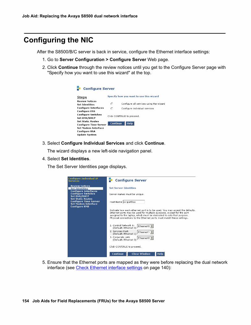
Job Aid: Replacing the Avaya S8500 dual network interface
154 Job Aids for Field Replacements (FRUs) for the Avaya S8500 Server
Configuring the NICAfter the S8500/B/C server is back in service, configure the Ethernet interface settings:
1. Go to Server Configuration > Configure Server Web page.
2. Click Continue through the review notices until you get to the Configure Server page with "Specify how you want to use this wizard" at the top.
3. Select Configure Individual Services and click Continue.
The wizard displays a new left-side navigation panel.
4. Select Set Identities.
The Set Server Identities page displays.
5. Ensure that the Ethernet ports are mapped as they were before replacing the dual network interface (see Check Ethernet interface settings on page 140):

Ethernet interface mapping
03-300529 Issue 4 January 2008 155
! Important:Important: If you check the Ethernet interface mapping with the ifconfig command at the
server’s CLI, the ports will be different from those listed above. See Ethernet interface mapping on page 155 for a complete explanation.
6. If you need to change the mappings, click on Continue.
The Configure Ethernet Interfaces page displays.
7. Make any changes and click Change. The status of the configuration update appears in the window.
8. When the update completes, the following message appears: Successfully configured ethernet interfaces.
Ethernet interface mappingThe Ethernet interface mapping is different for various Communication Manager releases:
l Release 3.1 Ethernet configurations
l Release 3.0 Ethernet configurations
l Release 2.2 Ethernet configurations

Job Aid: Replacing the Avaya S8500 dual network interface
156 Job Aids for Field Replacements (FRUs) for the Avaya S8500 Server
Release 3.1 Ethernet configurationsFor Release 3.1 use the Ethernet interface mapping in Table 7.
Release 3.0 Ethernet configurationsFor Release 3.0 use the Ethernet interface mapping in these two tables:
l For private/dedicated control networks use Table 8: Ethernet interface mapping (Release 3.0-private/dedicated network) on page 156.
l For combined Control Network with the Corporate LAN use Table 9: Ethernet interface mapping (Release 3.0-combined control with corporate LAN) on page 157.
Table 7: Ethernet interface mapping (Release 3.1)
Interface S8500C server
Web display (physical port)Linux shell IP configuration: logical port (ifconfig)
l Eth0-Control Network Al Eth1-Services laptopl Eth2-Internal SAMP interfacel Eth3-Control Network B (ESS)l Eth4-Enterprise LAN
Table 8: Ethernet interface mapping (Release 3.0-private/dedicated network)
Interface S8500 server S8500B server
Web display (physical port)
l Eth0-Control Network Al Eth1-Services portl Eth2-Corporate LANl Eth3-Not used in Release 3.0
l Eth0-Control Network Al Eth1-Services portl Eth2-Control Network Bl Eth3-Corporate LANl Eth4-SAMP Ethernet port (not
displayed on the Web)
Linux shell IP configuration: logical port (ifconfig)
l Eth0-Corporate LANl Eth1-not usedl Eth2-Control Network Al Eth3-Services port
l Eth0-Control Network Al Eth1-Control Network Bl Eth2-Corporate LANl Eth3-Services portl Eth4-SAMP Ethernet port

Ethernet interface mapping
03-300529 Issue 4 January 2008 157
Release 2.2 Ethernet configurationsFor Release 2.2 use the Ethernet interface mapping in these two tables:
l For private/dedicated control networks use Table 10: Ethernet interface mapping (Release 2.2-private/dedicated network) on page 157.
l For combined Control Network with the Corporate LAN use Table 11: Ethernet interface mapping (Release 2.2-combined control with corporate LAN) on page 158.
Table 9: Ethernet interface mapping (Release 3.0-combined control with corporate LAN)
Interface S8500 server S8500B server
Web display (physical port)
l Eth0-Control Network A/Corporate LAN
l Eth1-Services portl Eth2-Not used in Release 3.0l Eth3-Not used in Release 3.0
l Eth0-Control Network A/Corporate LAN
l Eth1-Services portl Eth2-Control Network Bl Eth3-Not used in Release 3.0l Eth4-SAMP Ethernet port (not
displayed on the Web)
Linux shell IP configuration: logical port (ifconfig)
l Eth0-Not used in Release 3.0l Eth1-Not used in Release 3.0l Eth2-Control Network A/Corporate
LANl Eth3-Services port
l Eth0-Control Network A/Corporate LAN
l Eth1-Control Network Bl Eth2-Not used in Release 3.0l Eth3-Services portl Eth4-SAMP Ethernet port
Table 10: Ethernet interface mapping (Release 2.2-private/dedicated network)
Interface S8500 server S8500B server
Web display (physical port)
l Eth0-Control Network Al Eth1-Services portl Eth2-Corporate LANl Eth3-Not used in Release 2.2
l Eth0-Control Network Al Eth1-Services portl Eth2-Corporate LANl Eth3-Not used in Release 2.2l Eth4-SAMP Ethernet port (not
displayed on the Web)
Linux shell IP configuration: logical port (ifconfig)
l Eth0-Corporate LANl Eth1-not usedl Eth2-Control Network Al Eth3-Services port
l Eth0-Control Network Al Eth1-Corporate LANl Eth2-Not usedl Eth3-Services portl Eth4-SAMP Ethernet port

Job Aid: Replacing the Avaya S8500 dual network interface
158 Job Aids for Field Replacements (FRUs) for the Avaya S8500 Server
Table 11: Ethernet interface mapping (Release 2.2-combined control with corporate LAN)
Interface S8500 server S8500B server
Web display (physical port)
l Eth0-Control Network A/Corporate LAN
l Eth1-Services portl Eth2-Not used in Release 2.2l Eth3-Not used in Release 2.2
l Eth0-Control Network A/Corporate LAN
l Eth1-Services portl Eth2-Not used in Release 2.2l Eth3-Not used in Release 2.2l Eth4-SAMP Ethernet port (not
displayed on the Web)
Linux shell IP configuration: logical port (ifconfig)
l Eth0-Not used in Release 2.2l Eth1-Not used in Release 2.2l Eth2-Control Network A/Corporate
LANl Eth3-Services port
l Eth0-Control Network A/Corporate LAN
l Eth1-Not used in Release 2.2l Eth2-Not used in Release 2.2l Eth3-Services portl Eth4-SAMP Ethernet port

Ethernet interface mapping
03-300529 Issue 4 January 2008 159
Testing connectivity to customer’s networkTo test network connections:
1. At the Web interface select Diagnostics > Ping.
The Ping screen displays (Figure 49: Ping screen on page 159).
Figure 49: Ping screen
2. In the Host Name or IP address field, type in the host name or IP address of a computer on the network.
3. Click Execute Ping.
4. Verify that the ping was successful, indicating that the server is connected to the customer’s network.
5. If DNS is administered, type in the host name of a computer on the network.
6. Click Execute Ping.
7. Verify that the ping was successful, indicating that DNS is working.

Job Aid: Replacing the Avaya S8500 dual network interface
160 Job Aids for Field Replacements (FRUs) for the Avaya S8500 Server
If available, have a customer representative do the following test from a computer on their network:
1. Click Start > Run to open the Run dialog box.
2. Type command and click OK to open an MS-DOS command window.
3. Type ping serveripaddress and click OK, where serveripaddress is the IP address of server.
4. Verify that the ping was successful.
5. If DNS is administered, type ping servername and press Enter, where servername is the host name of server.
6. Verify that the ping was successful.

03-300529 Issue 4 January 2008 161
Job Aid: Replacing the USB modem
! Important:Important: Always check the Avaya Support Website for Product Support Notices at
http://support.avaya.com and select Product Support Notices (All Avaya products) in the MOST POPULAR PRODUCTS IN SUPPORT section.
! Important:Important: This Job Aid applies to the replacement USB modem (Material ID 700405020)
used with Avaya S8700 series, the Avaya S8500B/C, and the S8300C servers only.
Removing the old modemTo remove the old or defective modem:
1. Remove the USB cable and phone line(s) from the rear of the modem:
Replacing the modemTo replace the USB modem:
1. Reconnect the USB cable and the phone line(s) to their respective connectors on the rear of the modem.
Job Aid: Replacing the USB modem
162 Job Aids for Field Replacements (FRUs) for the Avaya S8500 Server

03-300529 Issue 4 January 2008 163
Job Aid: Replacing the IP Server Interface
This procedure describes how to replace the TN2312BP (IPSI) circuit pack (Material ID 700260359) and applies to the Avaya S8700 series and the Avaya S8500 servers.
! Important:Important: Always check the Avaya Support Website for Product Support Notices at
http://support.avaya.com and select Product Support Notices (All Avaya products) in the MOST POPULAR PRODUCTS IN SUPPORT section.
Removing the IPSI circuit pack
ELECTROSTATIC ALERT:ELECTROSTATIC ALERT: Be sure to wear a grounded wrist strap, stand on an approved mat, or work on a
treated surface that will reduce the possibility of electrostatic discharge.
To remove the IP Server Interface (IPSI) circuit pack:
1. Look up the old IPSI circuit pack administration (display ipserver-interface location). Note whether the IPSI circuit pack has an administered (static) IP address or is supplied an IP address from a DHCP server.
2. Busyout the circuit pack (busyout ipserver-interface location).
3. Unlatch the circuit pack handle.
4. Pull the circuit pack completely out of the gateway carrier.

Job Aid: Replacing the IP Server Interface
164 Job Aids for Field Replacements (FRUs) for the Avaya S8500 Server
Replacing the IPSI circuit pack
ELECTROSTATIC ALERT:ELECTROSTATIC ALERT: Be sure to wear a grounded wrist strap, stand on an approved mat, or work on a
treated surface that will reduce the possibility of electrostatic discharge.
To replace the IPSI circuit pack:
1. Remove the new IPSI circuit pack from its protective packaging.
2. Slide the circuit pack into the slot all the way into the carrier and latch.
3. Release the circuit pack (release ipserver-interface location).
4. Go to either section:
l Re-assigning a static IP address on the IPSI circuit pack
l Assigning DHCP addressing
Note:Note: The 4-character LED on the IPSI circuit pack’s faceplate is used to display the
circuit pack status related to the Ethernet interfaces. If automatic IP address assignment via DHCP is enabled, the top character displays the Switch ID and the next two characters display the Cabinet Number. The last character is used to display the link status of the two Ethernet interfaces.
Re-assigning a static IP address on the IPSI circuit packIf the replacement TN2312AP or TN2312BP (IPSI) circuit pack has previously had a static address programmed, you must erase the existing IP address before re-assigning a new one.
! CAUTION:CAUTION: Failure to erase the existing IP address before re-using the IPSI circuit pack can
create serious network problems.
To set a static IP address on the replacement IPSI circuit pack:
1. Plug the circuit pack into the appropriate slot in the media gateway or if already plugged in, reseat it (unplug and replug).
2. Wait until the first letter (Switch ID) and the first (cabinet) digit on the LED display stops flashing (approximately 10 seconds), then press the recessed pushbutton on the faceplate to change the second digit to 0.
The LED display should now read A00.

Assigning DHCP addressing
03-300529 Issue 4 January 2008 165
Note:Note: This step is important because any other values in these fields cause the
following steps to fail.
3. Connect to the services port on the IPSI circuit pack.
4. Log in to the IPSI circuit pack as craft.
5. Type set control interface ipaddr netmask and press Enter.6. If required, set the gateway IP address (set control gateway gatewayIPaddr,
where gatewayIPaddr is the customer-provided IP address for the gateway).
7. Type exit to exit the session. Do not reset the IPSI circuit pack at this time.
Note:Note: If you reset the IPSI, this procedure will not work, and the IP address of the IPSI
will display as 0.0.0.0.
8. Watch the display on the IPSI circuit pack faceplate: it should change from A00 to IP.
9. If necessary to set V-LAN properties, Priority, Tag, ID, etc., log back into the IPSI to set these parameters.
Assigning DHCP addressingTo assign DHCP addressing to the replacement IPSI circuit pack:
1. Plug the circuit pack into the appropriate slot in the media gateway or if already plugged in, reseat it (unplug and replug).
2. While “IP” flashes on the display, push the recessed button on the IPSI faceplate and hold for 5 seconds.The display changes to A00 with the first character (A) flashing.
3. Push the recessed button to program the server ID and cabinet number for DHCP addressing.

Job Aid: Replacing the IP Server Interface
166 Job Aids for Field Replacements (FRUs) for the Avaya S8500 Server

03-300529 Issue 4 January 2008 167
Job Aid: Replacing the S8500 Compact Flash reader and card
Note:Note: This Job Aid applies to Avaya S8500/B/C servers only.
! Important:Important: Always check the Avaya Support Website for Product Support Notices at
http://support.avaya.com and select Product Support Notices (All Avaya products) in the MOST POPULAR PRODUCTS IN SUPPORT section.
Required equipmentVerify that you have the following equipment:
l Replacement Compact Flash Drive with flash card
- S8500C and S8300C servers use Material ID 195313
Remove the defective card driveTo remove the old or defective Compact Flash card drive:
1. Remove the USB connection for the reader from the USB port on the server.
2. Do not re-use the drive cable.
Replace the card driveTo replace the Compact Flash card drive:
1. Connect the USB cable from the card drive to the USB port on the server.

Job Aid: Replacing the S8500 Compact Flash reader and card
168 Job Aids for Field Replacements (FRUs) for the Avaya S8500 Server
Replace the Compact Flash cardTo replace the Compact Flash card (Material ID 700290430):
1. Place the card in the Compact Flash drive.
2. Select Data Backup/Restore >Format PC Card from the left-side navigation pane of the Maintenance Web interface.
The Format PC Card page displays (Figure 50).
Figure 50: Format PC Card page
3. Click on the Format button.
The system asks whether you want to format the PC card (see Warning above).
4. Click on Yes to format the card.

03-300529 Issue 4 January 2008 169
Job Aid: Replacing the Remote Supervisor Adapter (RSA)
! Important:Important: Always check the Avaya Support Website for Product Support Notices at
http://support.avaya.com and select Product Support Notices (All Avaya products) in the MOST POPULAR PRODUCTS IN SUPPORT section.
This document contains information and procedures for replacing the Remote Supervisor Adapter (RSA) board in the Avaya S8500 server. Detailed discussions of these topics follow:
l Backing up the RSA
l Backing up the server
l Powering down the server and RSA
l Removing the cover of the server
l Replacing the ribbon cable
l Removing the adapter support bracket and riser connector
l Installing the new RSA card
l Replacing the cover of the server
l Connecting the cables to the RSA
l Powering up the server
l Restoring the RSA configuration
l Upgrading the RSA firmware
l Checking the RSA installation
l Restoring the RSA defaults
The RSA is factory installed in PCI-X slot 1 of the S8500 server. Figure 51 shows the RSA faceplate and connectors.
For information about updating RSA firmware, see The Avaya RSA Users’ Guide, 555-245-702.

Job Aid: Replacing the Remote Supervisor Adapter (RSA)
170 Job Aids for Field Replacements (FRUs) for the Avaya S8500 Server
Figure 51: RSA faceplate and connectors
! CAUTION:CAUTION: Wear an antistatic wrist ground strap whenever handling the server or server
components. Connect the strap to an approved ground, such as an unpainted metal surface.
Backing up the RSA
Note:Note: When replacing the RSA in an S8500 server functioning as the Secure Services
Gateway (SSG) for a Secure Access and Control (SAC) deployment, back up the SSG configuration. For information on how to backup the SSG configuration, see Secure Services Gateway (SSG) Maintenance Guide, 19-300174. Backing up the server is not applicable for the SSG.
Backup the RSA configuration before shutting down the S8500 server. If it is not possible to backup the RSA at this time, locate the most recent RSA backup file before proceeding.
Complete the following steps to backup the RSA configuration:
1. Establish a connection from the services laptop to the RSA:
l Direct connect through a crossover cable from the laptop to the Ethernet port on the RSA
l Other network connection
2. Open a internet browser window.
3. In the address field of the browser, type the IP address for the RSA and press Enter. The Enter Network Password window appears (Figure 52).
Figure notes:
1. Power retaining clip2. External power supply connector3. Power and error LEDs
4. ASM RS-485 connector5. RS-232 serial connector6. Ethernet connector
h3msrsap LAO 071503
1 2 3 4 5 6
03-300529 Issue 4 January 2008 171
Figure 52: Enter Network Password window
4. In the Enter Network Password window, enter the default login of craft and the unique password for the RSA assigned to this location. The password can be obtained from the Automatic Registration Tool (ART) website.
5. In the RSA welcome window, select the no timeout value from the drop-down list. The no timeout value allows 60 minutes of use before disconnecting. See Figure 53 for an example of the welcome window.

Job Aid: Replacing the Remote Supervisor Adapter (RSA)
172 Job Aids for Field Replacements (FRUs) for the Avaya S8500 Server
Figure 53: RSA Welcome window
Note:Note: If the session times out unexpectedly, click Start New Session and Refresh.
6. Click Continue to start the session.
7. Click Configuration File in the navigation pane.
8. In the Backup ASM Configuration section click, view the current configuration summary.
03-300529 Issue 4 January 2008 173
Figure 54: Backing up the ASM configuration
9. After verifying that the current configuration summary settings are correct, click Close.
10. Now you can see the Backup ASM Configuration window (Figure 54).
11. In the Backup ASM Configuration section click Backup.
12. Enter a name for the backup fileset and choose a location to write the backup files.
13. Click on one:
l For Windows Internet Explorer: Select Save this file to disk and then OK.
l For Netscape Navigator: Select Save File.
Backing up the serverBefore replacing the RSA card, the server is powered down and all power connection removed. As a security measure, backup the server before powering it down.
1. Connect the laptop to the port labeled 2 (Eth 1) on the back of the server using the crossover cable.
2. Open a browser window on the laptop.
3. In the Address field of the browser, type in the URL for the server and press Enter.A welcome window opens (Figure 55: Sever Welcome window on page 174).

Job Aid: Replacing the Remote Supervisor Adapter (RSA)
174 Job Aids for Field Replacements (FRUs) for the Avaya S8500 Server
Figure 55: Sever Welcome window
4. Accept the Avaya certificate by clicking Yes.
5. Log into the server using the craft logon and the associated password (Figure 56: Logon window on page 175).

03-300529 Issue 4 January 2008 175
Figure 56: Logon window
6. Suppress alarm origination by clicking Yes.
7. Click Launch Maintenance Web Interface.
8. Select Data Backup/Restore > Backup Now from the navigation pane.
9. Select All data sets under the Data Sets heading.
10. Select one of the following backup methods:
l FTP
l Email
l Local PC card
11. If you want to encrypt the backup, select the Encrypt backup using pass phrase check box and enter a phrase in the box.
12. Click Start Backup.

Job Aid: Replacing the Remote Supervisor Adapter (RSA)
176 Job Aids for Field Replacements (FRUs) for the Avaya S8500 Server
Powering down the server and RSAAfter the backup is finished, complete the following steps to power down the server and the RSA.
1. From the server Web interface click Server > Shutdown Server.2. Select Delayed Shutdown.
3. Click Shutdown.
4. After the server shuts down, unplug the power cord from the back of the server.
5. Unplug the external power supply connection (Note 2 in Figure 51: RSA faceplate and connectors on page 170) from the RSA.
! DANGER:DANGER: Ensure that all power is removed from the server and the RSA.
6. Disconnect the modem from the RS-232 port on the RSA.
7. Disconnect and label the LAN connection (if used) from the Ethernet port on the RSA.
8. Pull the server forward so that the server rails expand and the retaining clips on the rails click into place.

03-300529 Issue 4 January 2008 177
Removing the cover of the serverComplete the following steps to remove the cover of the server:
1. Unscrew the two captive screws on the back of the server, as shown in Figure 57: Captive screws on page 177.
Figure 57: Captive screws
2. Slide the server cover back from the front panel until the cover’s tabs are released from the top slot of the front panel.
3. Lift the cover straight up and move it away from the server.
Figure notes:
1. Captive screws
h3mscaps LAO 070103
disc
1

Job Aid: Replacing the Remote Supervisor Adapter (RSA)
178 Job Aids for Field Replacements (FRUs) for the Avaya S8500 Server
Replacing the ribbon cableThe 20-pin ribbon cable connects the RSA to the server system board and is required for power and data transfer. The ribbon cable is shipped in the same box as the RSA. Replace the ribbon cable before installing the new RSA card.
Complete the following steps to remove and replace the ribbon cable:
1. Remove one side of the ribbon cable from the system-management connector on the system board (CN-12) and the other side from the system-management connector on the RSA.
2. Connect one side of the new ribbon cable to J44 on the system board. You will install the other side of the ribbon cable to the new RSA (see Step 3 in the procedure titled, Installing the new RSA card on page 180).
Removing the adapter support bracket and riser connectorThe RSA card resides in PCI-X slot 1 located under the adapter support bracket. Remove the adapter support bracket and the riser connector together by performing the following steps:
1. Loosen the captive screw located to the right of the slot labeled PCI 1.
2. The riser connector must be removed by pulling straight up on the adapter support bracket. Place one finger under the screw on the far end of the riser connector and one finger under the adapter support bracket near the captive screw and pull straight up, as shown in Figure 58: Removing the RSA from the riser connector on page 179.

03-300529 Issue 4 January 2008 179
Figure 58: Removing the RSA from the riser connector
3. Remove the RSA card from PCI-X slot 1 by pulling the card gently out of the riser card connector.
Figure notes:
1. RSA2. Adapter support bracket3. Riser card connector
4. Connector5. Captive screw
h3msrrsa LAO 071803
1
2
LINKTX/RX
LINKTX/RX
PCI1
PCI 2
100-127 -, 3,0A, 50/60 Hz
200-240 -, 1,5A, 50/60 Hz
133 MHz/64 Bit, 100 MHz/64 Bit
1
2
3
4
5

Job Aid: Replacing the Remote Supervisor Adapter (RSA)
180 Job Aids for Field Replacements (FRUs) for the Avaya S8500 Server
Installing the new RSA cardTo install the new RSA card in the server:
1. Touch the static-protective package containing the adapter to any unpainted mental surface of the S8500 server. Then remove the RSA card from the static-protective package. Avoid touching the components and gold-edge connectors on the RSA card.
2. Carefully grasp the RSA by the top edges or upper comers, component side facing up, and align it with the PCI-X slot one opening. Press the RSA firmly into the riser card connector.
! CAUTION:CAUTION: Make sure the RSA card is completely and correctly seated in the riser card
connector before you turn on the S8500 server. Incomplete insertion might cause damage to the system board or RSA card.
3. Connect the ribbon cable to the system-management connector located on the back on the card.
4. Replace the adapter support bracket lining up the tabs on each side of the bracket and the screw holes on the riser card connector.
5. Align the riser card with the connector and the tabs on the adapter support bracket with the provided holes and press the riser card firmly into the connector.
6. Tighten the captive screw to the right of the slot.
7. Route the ribbon cable so that it does not block the flow of air from the fans.
Replacing the cover of the serverTo replace the cover of the server:
1. Replace the cover onto the server.
2. Slide the cover forward so the cover’s tabs slide into place under the top slots of the front panel.
3. Finger-tighten the thumb screws on the back of the server.
4. Release the retaining tabs on the rails and slide the S8500 server back into place on the data rack.

03-300529 Issue 4 January 2008 181
Connecting the cables to the RSATo connect the cables to the RSA:
1. Connect the external power supply (Note 2 in Figure 51: RSA faceplate and connectors on page 170) to the RSA.
Note:Note: Do not apply power to the server yet.
2. Connect the modem to the RS-232 port.
3. Do not plug in the LAN connection (if used). You will need to access the Ethernet port on the RSA once power is restored.
Powering up the serverComplete the following steps if you want to start the server at this time:
1. Plug the power cord in the back of the server.
2. Press the Power Button located on the front on the right hand side.
3. Log into the server to ensure that the startup is complete.
Restoring the RSA configurationComplete the following steps to restore the RSA configuration information:
1. Connect the services laptop to the Ethernet port on the RSA using a crossover cable.
2. Open a browser window.
3. Type 192.11.13.6 in the address field of the browser, and press Enter.4. The Enter Network Password window appears.
5. Enter the default login of craft and default password of passw0rd (with a zero).
6. In the RSA welcome screen, select the no timeout value from the drop-down list (see Figure 59: RSA Welcome screen on page 182). The no timeout value allows 60 minutes of use before disconnecting.

Job Aid: Replacing the Remote Supervisor Adapter (RSA)
182 Job Aids for Field Replacements (FRUs) for the Avaya S8500 Server
Figure 59: RSA Welcome screen
7. Click Continue.
8. Click Configuration File in the navigation pane.
9. In the Restore ASM Configuration section, click Browse. See Figure 60: Restoring ASM configuration on page 183 for an example of the restoring ASM configuration window.

03-300529 Issue 4 January 2008 183
Figure 60: Restoring ASM configuration
10. Click the saved configuration file that you want to restore and click Open.
The file will appear in the box.
11. Click Restore Configuration.
A progress window shows the status of the restore.
A confirmation window opens when the update is completed.
12. Click OK to restart the RSA.
13. Click OK to close the current browser window.
Upgrading the RSA firmwareAfter installing the new RSA board, you must ensure that its firmware version is compatible with the release of Communication Manager running on the S8500 server. This might involve upgrading the RSA firmware to the latest version. Before that you must first use these two procedures:
l Checking the firmware version on the new RSA on page 184
l Checking for the compatible firmware version on page 184

Job Aid: Replacing the Remote Supervisor Adapter (RSA)
184 Job Aids for Field Replacements (FRUs) for the Avaya S8500 Server
Checking the firmware version on the new RSA
To check the version of firmware on the new RSA
1. Log into the RSA card through a browser window.
2. Select Server > Monitors > System Health > Vital Product Data.3. At the bottom of the report the Advanced System Management (ASD) Vital Product Data
(VPD) shows the Build ID.
4. Also check the readme.txt file for the Version and Revision numbers.
Note:Note: If you have root permission, establish a command line interface (CLI) connection
and type getvpd to obtain the Vital Product Data report.
Checking for the compatible firmware version
To check what RSA firmware version is compatible with the release of Communication Manager that is running on the server:
1. Open an browser window on your laptop.
2. Enter http://www.avaya.com/support in the address field.
3. Highlight Support in the top heading.
4. Highlight and click Software and Firmware Downloads.
5. Click RSA in the left pane.
6. Check See All Releases.
7. Select the Communication Manager release running on the server.
8. Compare the firmware version listed with the version on the new RSA board.
9. If the new RSA firmware is compatible, complete the section.
Upgrading the RSA firmware
Use this procedure to upgrade the RSA firmware:
1. On your laptop, click on the required version of RSA firmware.
A download window opens.
2. Click Save.
A Save As window opens.
3. Choose the location to save and file and a file name. Click Save.
A confirmation window opens when the transfer is complete.

03-300529 Issue 4 January 2008 185
Note:Note: The RSA firmware is loaded into the RSA card as three separate files. So, either
there will be three files on the support site, or the user will download a single file and split it into the three separate files with WinZip or a similar program.
4. Log into the RSA using the instructions found under the Backing up the RSA on page 170.
5. In the navigation pane, select Firmware Update.
6. In the Choose File window, click Browse. Go to the saved location from Step 3.
7. Click on one of the three firmware files and then click Open.
The file name appears in the box next to Browse.
8. Click Update to begin the firmware update.
A progress window opens as the files are transferring to temporary storage on the RSA.
A confirmation window opens when the transfer is complete.
9. Verify that the file in the confirmation window is the file you want to update. If you do not want to continue click Cancel.
10. To continue with the firmware update click Continue.
A progress window opens as the firmware on the RSA updates. A confirmation window appears when the update is completed.
11. Repeat Step 6 through Step 9 for the remaining two firmware files.
12. Restart the RSA by clicking on Restart.13. Click OK to continue.
14. Click OK to close the browser window.
15. Log into the RSA.
Checking the RSA installationCheck the following to ensure that the installation was successful:
1. Under Monitors, System Health ensure that the RSA can read the system health of the S8500.
If the RSA cannot read the system health of the S8500:l The RSA may not be seated correctly in the riser card. Follow the instruction starting at
Powering down the server and RSA on page 176 to reseat the RSA.l The RSA may be defective.l The S8500 server may be defective. Contact the TSO for verification and instructions.l The ribbon cable might not be seated at either or both ends.

Job Aid: Replacing the Remote Supervisor Adapter (RSA)
186 Job Aids for Field Replacements (FRUs) for the Avaya S8500 Server
2. Under ASM Control, Login Profiles verify that the login information was restored.
If the login information is not correct:
l Restore the configuration information file again (Restoring the RSA configuration on page 181).
or
l Manually input the correct information.
3. Under ASM Control, Alerts verify that the remote alert recipients are correct.
If the alert information is not correct:
a. Restore the configuration information file again (Restoring the RSA configuration on page 181) or manually input the correct information.
b. Generate an alarm to a test alarm by clicking Generate Test Alert. If the RSA has LAN connectivity, send an SNMP alert. Call the Avaya alarming group and verify the alarm was received.
4. Under Monitors, Event Log ensure that there are no errors (red X) listed in the log.
5. If an error exists:
a. Check the timestamp of the error.
b. If the error occurred after you replaced the RSA, contact your technical support representative for further instructions.
Restoring the RSA defaults
! CAUTION:CAUTION: DO NOT select Restore Defaults. Doing so removes the Avaya defaults that are
superimposed over the manufacturers’ resulting in loss of access to the RSA card. “Restore” in this instance means reinstating the manufacturer’s factory default settings and rendering the server incapable of providing IP Telephony.
Avaya defaults can be restored manually or by restoring the Avaya default file:
l To manually restore the default file use the steps outlined in the Configuration File section of the Installing the S8500 server with the G650 Media Gateway, 555-245-107.
l To restore the Avaya default file go to http://www.avaya.com/support.