job sheet 5 psychrometrics - lab-volt · job sheet 5 – psychrometrics © festo didactic 88271-20...
TRANSCRIPT
© Festo Didactic 88271-20 117
In this job sheet, you will evaluate how much heat is transferred by the heat pump to the air in heating and cooling mode using a psychrometric chart.
Energy transferred by the heat pump in heating mode
In this part of the job sheet, you will measure the temperature, speed, and relative humidity at the air intake and distribution register of the heat pump. With these values, you will plot the process on a psychrometric chart to find the amount of energy the heat pump is transferring.
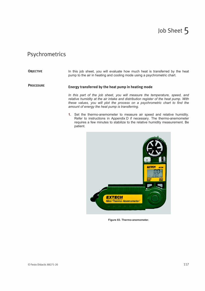
1. Set the thermo-anemometer to measure air speed and relative humidity. Refer to instructions in Appendix D if necessary. The thermo-anemometer requires a few minutes to stabilize to the relative humidity measurement. Be patient.
Figure 83. Thermo-anemometer.
Psychrometrics
Job Sheet 5
OBJECTIVE
PROCEDURE
Job Sheet 5 – Psychrometrics
118 © Festo Didactic 88271-20
2. Perform the following settings on your training system:
Main power switch .............................................................................. Off
Thermostat ........................................................................ Heating mode
Temperature set point ....................... 5°C (9°F) above room temperature
Valve HV-1 ..................................................................................... Open
Valve HV-2 ..................................................................................... Open
Valve HV-3 ..................................................................................... Open
Valve HV-4 ..................................................................................... Open
Valve HV-5 ..................................................................................... Open
Valve HV-6 ..................................................................................... Open
Valve HV-7 ..................................................................................... Open
Valve HV-8 ................................................................................... Closed
Valve HV-9 ....................................................... No adjustments required
Valve HV-10 ................................................ Handle in horizontal position
Valve HV-11 ................................................................................... Open
Valve HV-12 ................................................................................... Open
Valve HV-13 ................................................................................... Open
Pressure gauge PI-1 selector switch ............................................... Right
Pressure gauge PI-2 selector switch ............................................... Right
Desuperheater On/Off switch ............................................................ Off
Priming tank three-way valves ......................................................
Pumping station three-way valves .............................................
Air distribution register .................................................................... Open
3. Set the main power switch to On.
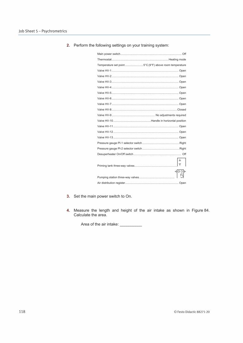
4. Measure the length and height of the air intake as shown in Figure 84. Calculate the area.
Area of the air intake: __________
Job Sheet 5 – Psychrometrics
© Festo Didactic 88271-20 119
Figure 84. Air intake.
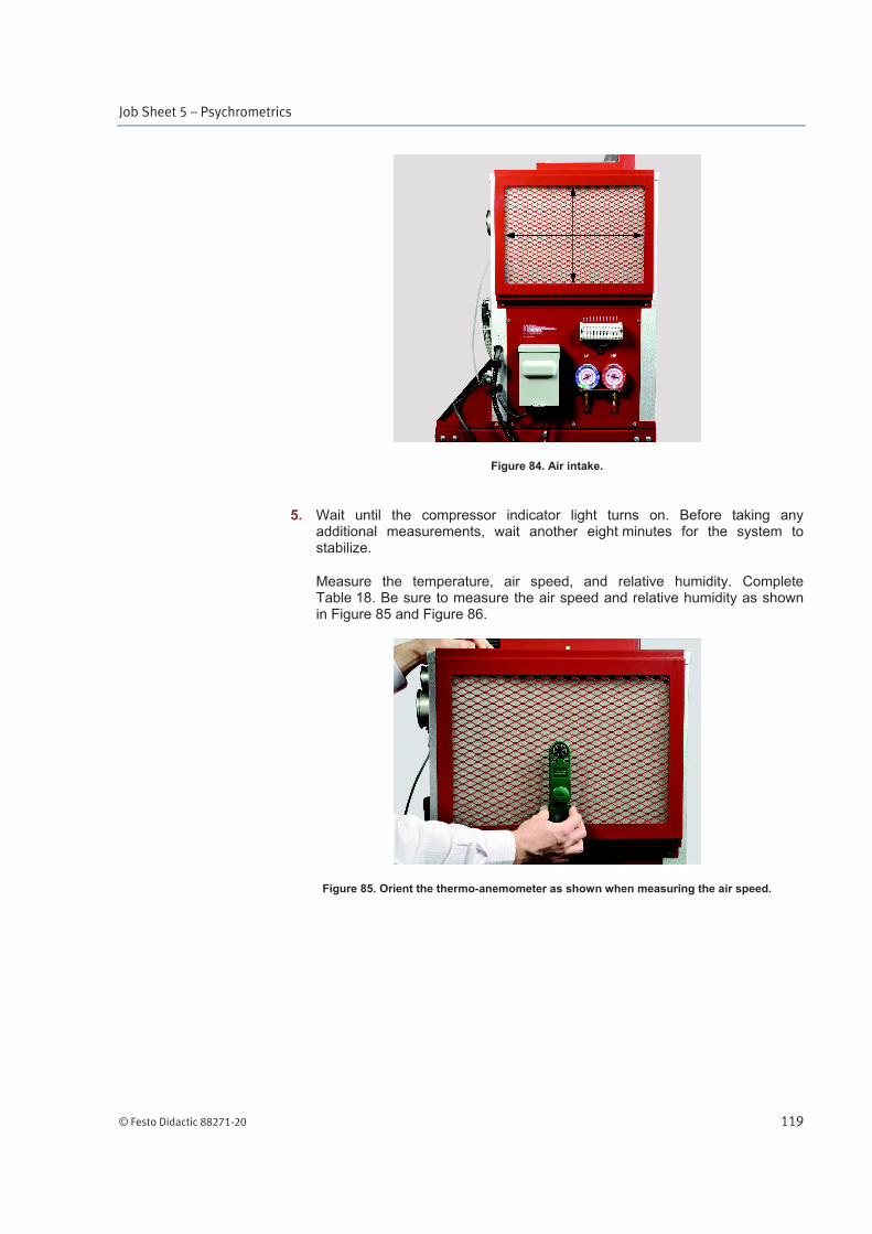
5. Wait until the compressor indicator light turns on. Before taking any additional measurements, wait another eight minutes for the system to stabilize.
Measure the temperature, air speed, and relative humidity. Complete Table 18. Be sure to measure the air speed and relative humidity as shown in Figure 85 and Figure 86.
Figure 85. Orient the thermo-anemometer as shown when measuring the air speed.
Job Sheet 5 – Psychrometrics
120 © Festo Didactic 88271-20
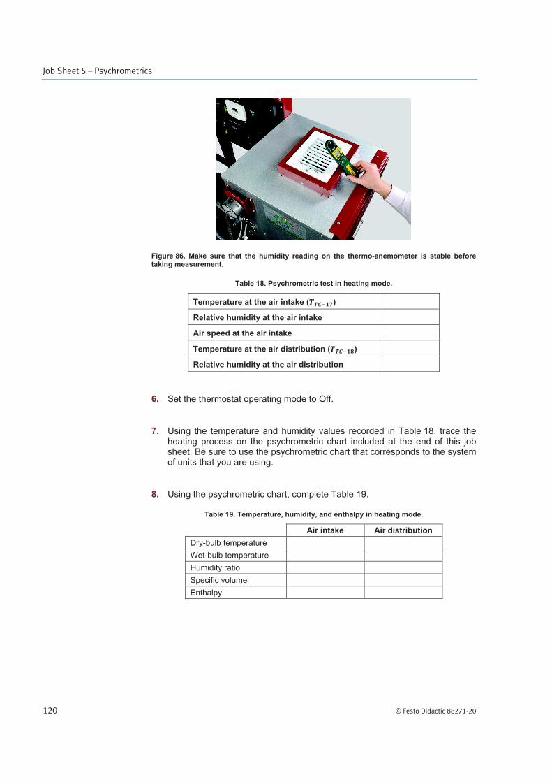
Figure 86. Make sure that the humidity reading on the thermo-anemometer is stable before taking measurement.
Table 18. Psychrometric test in heating mode.
Temperature at the air intake ( )
Relative humidity at the air intake
Air speed at the air intake
Temperature at the air distribution ( )
Relative humidity at the air distribution
6. Set the thermostat operating mode to Off.
7. Using the temperature and humidity values recorded in Table 18, trace the heating process on the psychrometric chart included at the end of this job sheet. Be sure to use the psychrometric chart that corresponds to the system of units that you are using.
8. Using the psychrometric chart, complete Table 19.
Table 19. Temperature, humidity, and enthalpy in heating mode.
Air intake Air distribution
Dry-bulb temperature
Wet-bulb temperature
Humidity ratio
Specific volume
Enthalpy
Job Sheet 5 – Psychrometrics
© Festo Didactic 88271-20 121
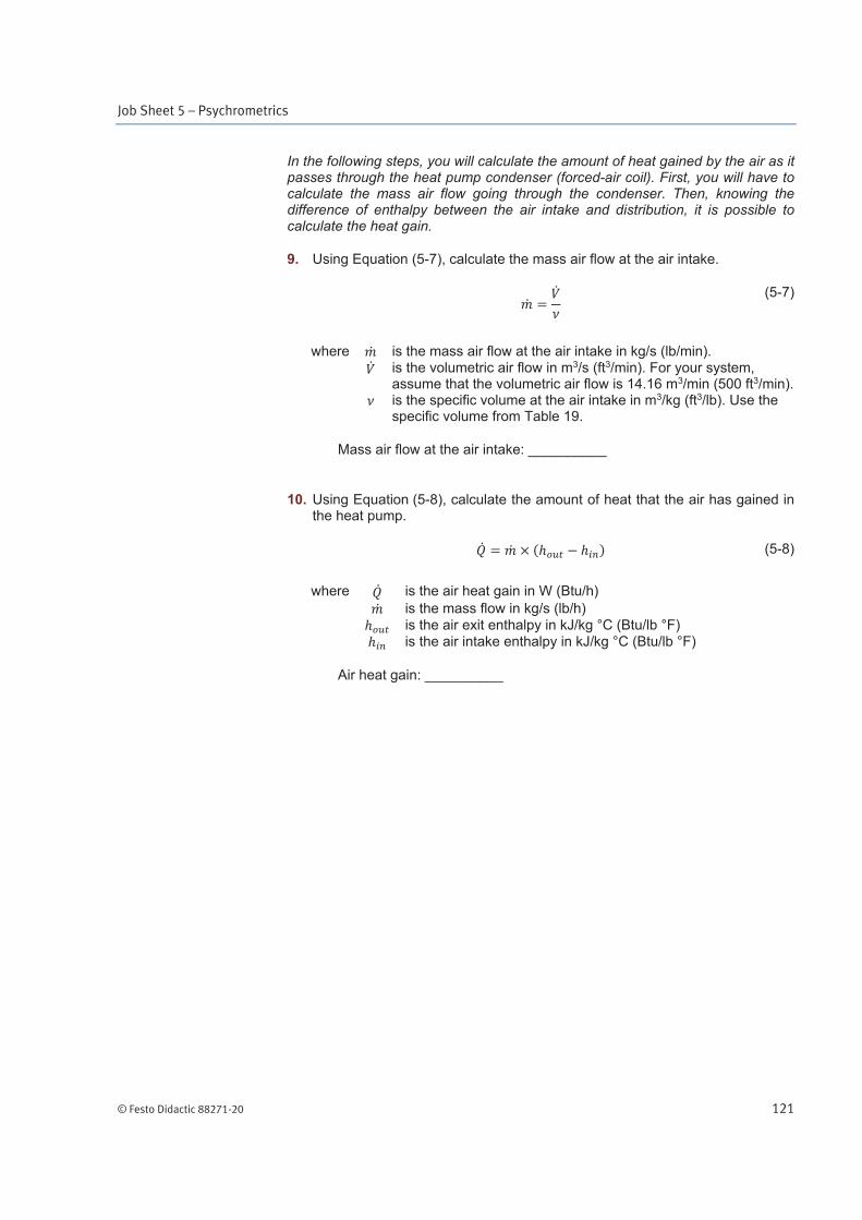
In the following steps, you will calculate the amount of heat gained by the air as it passes through the heat pump condenser (forced-air coil). First, you will have to calculate the mass air flow going through the condenser. Then, knowing the difference of enthalpy between the air intake and distribution, it is possible to calculate the heat gain.
9. Using Equation (5-7), calculate the mass air flow at the air intake.
(5-7)
where is the mass air flow at the air intake in kg/s (lb/min). is the volumetric air flow in m3/s (ft3/min). For your system,
assume that the volumetric air flow is 14.16 m3/min (500 ft3/min). is the specific volume at the air intake in m3/kg (ft3/lb). Use the
specific volume from Table 19.
Mass air flow at the air intake: __________
10. Using Equation (5-8), calculate the amount of heat that the air has gained in the heat pump.
(5-8)
where is the air heat gain in W (Btu/h)
is the mass flow in kg/s (lb/h)
is the air exit enthalpy in kJ/kg °C (Btu/lb °F) is the air intake enthalpy in kJ/kg °C (Btu/lb °F)
Air heat gain: __________
Job Sheet 5 – Psychrometrics
122 © Festo Didactic 88271-20
Energy transferred by the heat pump in cooling mode
In the following steps, you will repeat the previous experiment using the cooling mode. Depending on the current air conditions, this process may be a simple cooling process or a cooling process with dehumidification. You will trace this process on a psychrometric chart and calculate the amount of heat absorbed by the heat pump evaporator (forced-air coil).
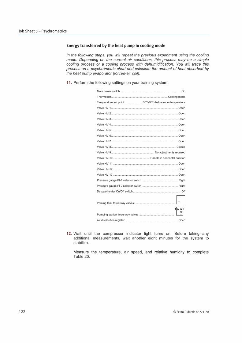
11. Perform the following settings on your training system:
Main power switch .............................................................................. On
Thermostat ........................................................................ Cooling mode
Temperature set point ....................... 5°C (9°F) below room temperature
Valve HV-1 ..................................................................................... Open
Valve HV-2 ..................................................................................... Open
Valve HV-3 ..................................................................................... Open
Valve HV-4 ..................................................................................... Open
Valve HV-5 ..................................................................................... Open
Valve HV-6 ..................................................................................... Open
Valve HV-7 ..................................................................................... Open
Valve HV-8 ................................................................................... Closed
Valve HV-9 ....................................................... No adjustments required
Valve HV-10 ................................................ Handle in horizontal position
Valve HV-11 ................................................................................... Open
Valve HV-12 ................................................................................... Open
Valve HV-13 ................................................................................... Open
Pressure gauge PI-1 selector switch ............................................... Right
Pressure gauge PI-2 selector switch ............................................... Right
Desuperheater On/Off switch ............................................................ Off
Priming tank three-way valves ......................................................
Pumping station three-way valves .............................................
Air distribution register .................................................................... Open
12. Wait until the compressor indicator light turns on. Before taking any additional measurements, wait another eight minutes for the system to stabilize.
Measure the temperature, air speed, and relative humidity to complete Table 20.
Job Sheet 5 – Psychrometrics
© Festo Didactic 88271-20 123
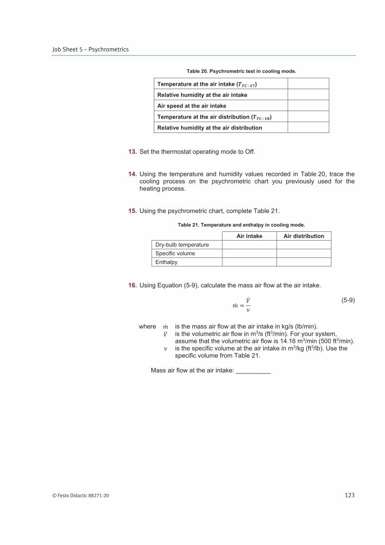
Table 20. Psychrometric test in cooling mode.
Temperature at the air intake ( )
Relative humidity at the air intake
Air speed at the air intake
Temperature at the air distribution ( )
Relative humidity at the air distribution
13. Set the thermostat operating mode to Off.
14. Using the temperature and humidity values recorded in Table 20, trace the cooling process on the psychrometric chart you previously used for the heating process.
15. Using the psychrometric chart, complete Table 21.
Table 21. Temperature and enthalpy in cooling mode.
Air intake Air distribution
Dry-bulb temperature
Specific volume
Enthalpy
16. Using Equation (5-9), calculate the mass air flow at the air intake.
(5-9)
where is the mass air flow at the air intake in kg/s (lb/min).
is the volumetric air flow in m3/s (ft3/min). For your system, assume that the volumetric air flow is 14.16 m3/min (500 ft3/min).
is the specific volume at the air intake in m3/kg (ft3/lb). Use the specific volume from Table 21.
Mass air flow at the air intake: __________
Job Sheet 5 – Psychrometrics
124 © Festo Didactic 88271-20
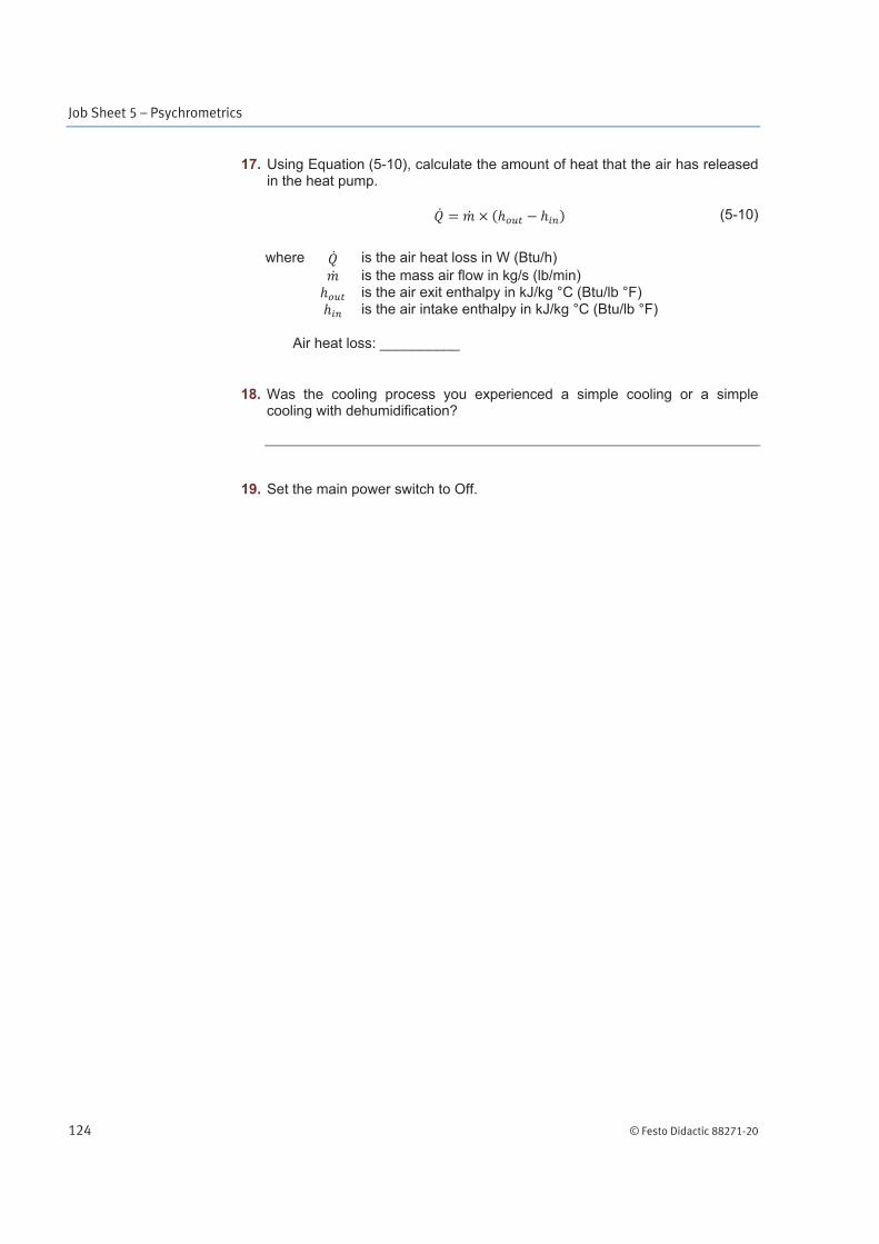
17. Using Equation (5-10), calculate the amount of heat that the air has released in the heat pump.
(5-10)
where is the air heat loss in W (Btu/h)
is the mass air flow in kg/s (lb/min) is the air exit enthalpy in kJ/kg °C (Btu/lb °F)
is the air intake enthalpy in kJ/kg °C (Btu/lb °F)
Air heat loss: __________
18. Was the cooling process you experienced a simple cooling or a simple cooling with dehumidification?
19. Set the main power switch to Off.
Job Sheet 5 – Psychrometrics
© Festo Didactic 88271-20 125
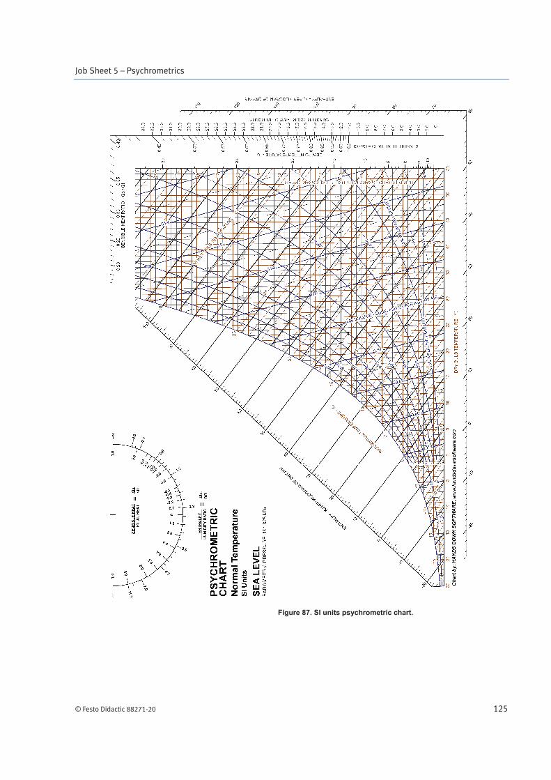
Figure 87. SI units psychrometric chart.
Job Sheet 5 – Psychrometrics
126 © Festo Didactic 88271-20
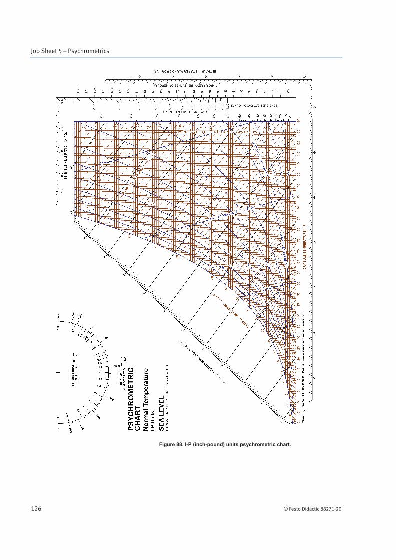
Figure 88. I-P (inch-pound) units psychrometric chart.

Job Sheet 5 – Psychrometrics
© Festo Didactic 88271-20 127
Name: ______________________________ Date: ____________________
Instructor's approval: _______________________________________________