john deere (4630 & r403x prop. main lift option) … · 2017-02-28 · list or the installation...
TRANSCRIPT

John Deere (4630 & R403x Prop. Main Lift Option)
Installation Manual JD13

Printed in Canada Copyright 2014 by NORAC Systems International Inc. Reorder P/N: UC4.5-JD13-INST Rev A (John Deere 4630 & R403X Prop. Main Lift Option)
NOTICE: NORAC Systems International Inc. reserves the right to improve products and their specifications without notice and without the requirement to update products sold previously. Every effort has been made to ensure the accuracy of the information contained in this manual. The technical information in this manual was reviewed at the time of approval for publication.

Contents
1 Introduction ................................................................................................................ 1
2 Kit Parts ...................................................................................................................... 2
3 Main Lift Sensor Installation ..................................................................................... 5
4 Hydraulic Installation ................................................................................................ 7
5 Electrical Installation ................................................................................................. 9
6 Software Setup ......................................................................................................... 10
7 Cable Drawings ........................................................................................................ 11

1
1 Introduction
Congratulations on your purchase of the NORAC UC4.5 Spray Height Control System. This system is manufactured with top quality components and is engineered using the latest technology to provide operating reliability unmatched for years to come.
When properly used the system can provide protection from sprayer boom damage, improve sprayer efficiency, and ensure chemicals are applied correctly.
Please take the time to read this manual completely before attempting to install the system. A thorough understanding of this manual will ensure that you receive the maximum benefit from the system.
Your input can help make us better! If you find issues or have suggestions regarding the parts list or the installation procedure, please don’t hesitate to contact us.
Every effort has been made to ensure the accuracy of the information contained in this manual. All parts supplied are selected to specially fit the sprayer to facilitate a complete installation. However, NORAC cannot guarantee all parts fit as intended due to the variations of the sprayer by the manufacturer.
Please read this manual in its entirety before attempting installation.

2
2 Kit Parts
2.1 Hydraulic Plumbing
Figure 1: JD13 Hydraulic Plumbing
3
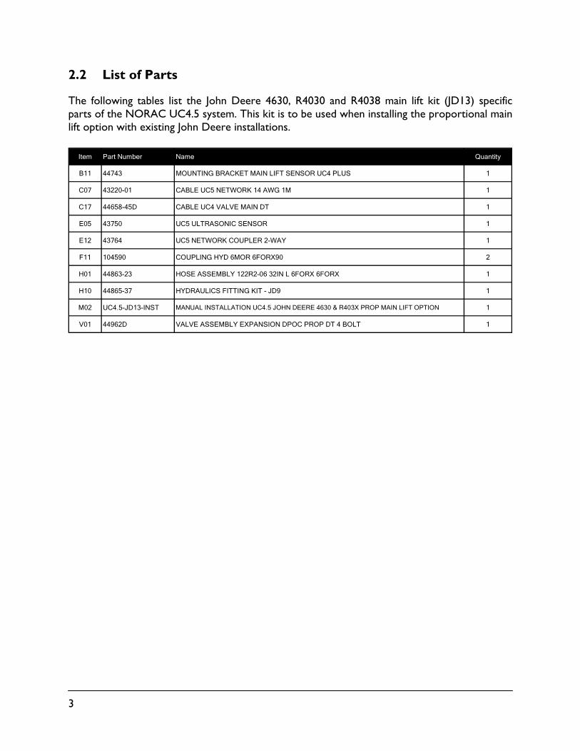
2.2 List of Parts
The following tables list the John Deere 4630, R4030 and R4038 main lift kit (JD13) specific parts of the NORAC UC4.5 system. This kit is to be used when installing the proportional main lift option with existing John Deere installations.
Item Part Number Name Quantity
B11 44743 MOUNTING BRACKET MAIN LIFT SENSOR UC4 PLUS 1
C07 43220-01 CABLE UC5 NETWORK 14 AWG 1M 1
C17 44658-45D CABLE UC4 VALVE MAIN DT 1
E05 43750 UC5 ULTRASONIC SENSOR 1
E12 43764 UC5 NETWORK COUPLER 2-WAY 1
F11 104590 COUPLING HYD 6MOR 6FORX90 2
H01 44863-23 HOSE ASSEMBLY 122R2-06 32IN L 6FORX 6FORX 1
H10 44865-37 HYDRAULICS FITTING KIT - JD9 1
M02 UC4.5-JD13-INST MANUAL INSTALLATION UC4.5 JOHN DEERE 4630 & R403X PROP MAIN LIFT OPTION 1
V01 44962D VALVE ASSEMBLY EXPANSION DPOC PROP DT 4 BOLT 1

4
2.3 Hydraulic Fitting Kit Details (P/N: 44865-37)
Item Part Number Name Quantity Picture
F03 104586 TEE ADAPTER - 6FORXR 6MORT 1
F05 44917 MALE ADAPTER - 6MB 6MOR 1
*F08 44926 ORIFICE INSERT 3/64" 1
F09 104369 PLUG - 6MBP 1
6 M B - 6 M OR X 90SIZE IN 1/16TH'S
GENDER: MALE OR FEMALE
90° ANGLESWIVELTYPEGENDERSIZE
TYPE:B - ORBJ - JICOR - FLAT FACEP - PIPE
Fitting Name Example:
Do not use high speed power tools/drills when installing hardware.
The use of dielectric grease is not recommended on any NORAC electrical connections.
To ensure all stainless steel hardware does not gall or seize apply a light coating of the supplied Permatex Anti-seize grease to all threaded parts upon installation. Permatex Anti-seize lubricant is preferred, but other similar anti-seize products may be used.

5
3 Main Lift Sensor Installation
1. Assemble the main lift sensor bracket (B11) as shown in Figure 2.
Figure 2: Main Lift Bracket Assembly
2. Mount the main lift bracket as shown in Figure 3 for 4630 or Figure 4 for R403x. The bracket should position the sensor approximately in the center of the sprayer, forward of the boom.
3. Mount the ultrasonic sensor to the main lift bracket. Run the sensor cable down the center of the main lift bracket tube.
Figure 3: 4630 Main Lift Bracket Mounting
Figure 4: R403x Main Lift Bracket Mounting
Avoid mounting the main lift sensor over or near a wheel-track. Measurements from the wheel-track do not provide an accurate crop height and will cause measurement and control error.
Ensure the bracket does not collide with any other part of the sprayer throughout the full range of main lift motion.

6
3.1 Ultrasonic Sensor Mounting Guidelines
The following guidelines will ensure optimal sensor performance and prevent sensor measurement error.
1. In its lowest position, the sensor must be 9 inches (23 cm) or more from the ground (A).
2. The centerline of the acoustic cone should be approximately vertical at normal operating heights (A).
3. The bottom of the sensor must be at least 9 inches in front of the spray nozzles and boom structure (B). (This does not apply for the main lift sensor)
4. The bottom of the sensor must be at least 9 inches above the spray nozzles (C).
5. Ensure there are no other obstructions with a 12 inch (23 cm) diameter circle projected directly below the sensor (D).
Figure 5: Sensor Mounting Guidelines

7
4 Hydraulic Installation
Ensure all pressure has been bled from the system before disconnecting any lines or fittings. Hydraulic pressure will exist on the main lift circuit unless the main lift is all the way down.
Component failure due to oil contamination is not covered under the NORAC UC4.5 system warranty. It is recommended that a qualified technician perform the hydraulic installation.
4.1 Expansion Block Assembly
1. Use Figure 1 as a reference for installing the hydraulics.
2. Loosen the existing 2-station valve block so that it can be moved and/or twisted for the installation of the expansion block.
3. Remove the four 4MBP plugs from the 2 station valve block.
4. Coat the four o-rings in hydraulic oil and install them into the expansion block. Ensure the o-rings are seated properly.
5. Attach the expansion block to the 2 station block using the included spring washers and bolts.
6. Tighten the bolts to 31 ft-lbs.
Figure 6: NORAC Expansion Block Assembly

8
4.2 Hydraulic Plumbing
1. Install the orifice (F08) and the 6MB 6MOR fitting (F05) into the “B” port of the expansion block.
2. Install the 6MBP plug (F09) into the “A” port of the expansion block.
3. If the valve block is not already installed on the sprayer, install it as outlined in the UC4.5 Spray Height Control installation manual.
4. If installing on a R4030 or R4038, install a 6MOR 6FORX90 fitting (F11) onto each end of hose H01.
5. Attach hose H01 to the “B” port on the expansion block. Route the free end of the hose to the John Deere valve block.
6. Tee in H01 to the existing main lift line on the John Deere valve block, using the tee fitting (F03).
Figure 7: 4630 Main Lift Tee Location
Figure 8: R403x Main Lift Tee Location
Ensure no hydraulic components will interfere with any sprayer parts or be pulled tight at any time.

9
5 Electrical Installation
Figure 9: Cable Connections
Only parts shown in black are included in this kit.
1. Connect the 6-pin shroud (S6) on C17 to T6 on C11 (previously installed).
2. Connect the 3-pin tower (T3) on C17 to S3 on C11.
Two connectors on C17 will remain disconnected. These are used when installing other UC4.5 options.
3. Install the two 2-pin connectors on the end of cable C17 to the expansion block.
The connector marked “Main Up” goes on the port side of the block. The port side of the block is the side with the hose connections.
4. Connect the main lift sensor to the 8-way coupler using cable C07 and a 2-way coupler (E12). Cable C07 and item E12 may not be needed if the 8-way coupler is mounted close enough to the main lift sensor.

10
6 Software Setup
1. Start up the sprayer and test the sprayer’s functionality. The control panel does not need to be powered on for the original switches to function.
Confirm that the cabling and hoses are agreeable to the entire range of motion.
2. If any functions do not work, review the hydraulic and electrical portions of this manual to check for proper installation.
3. Turn on the power for the control panel using the switch on the side of the chassis.
4. Refer to the UC4.5 Spray Height Control Operator’s Manual to run an automatic install with the JD9 type selected.

11
7 Cable Drawings
7.1 ITEM C07: 43220-01 - CABLE UC5 NETWORK 14 AWG - 1M

12
7.2 ITEM C17: 44658-45D – CABLE UC4 VALVE MAIN DT

Canada NORAC Systems International Inc.
Phone: (+1) 306 664 6711 Toll Free: 1 800 667 3921
Shipping Address: 3702 Kinnear Place
Saskatoon, SK S7P 0A6
United States NORAC, Inc.
Phone: (+1) 952 224 4142 Toll Free: 1 866 306 6722
Shipping Address: 6667 West Old Shakopee Road, Suite 111
Bloomington, MN 55438
Europe NORAC Europe
Phone: (+33) (0)4 26 47 04 42 Shipping Address:
Rue de l’hermitage 01090 GUEREINS
France
www.norac.ca