joint european x-ray monitor jem - x · joint european x-ray monitor jem - x x-ray monitor for the...
TRANSCRIPT
JOINT EUROPEAN X-RAY MONITOR
JEM - X
X-RAY MONITOR FOR THE INTEGRAL MISSION
Experiment Interface Document Part B
Issue 5 Revision 1
December 1999
Approval _______________________________ DSRIDate JEM-X PI
_______________________________ ESADate Name

Danish Space Research Institute Page: iiJEMX/EID-B_5.1 JEM-X Issue 5. Rev. 1Experiment Interface Document Part B INTEGRAL Date: 1999-12-22

Danish Space Research Institute Page: iiiJEMX/EID-B_5.1 JEM-X Issue 5. Rev. 1Experiment Interface Document Part B INTEGRAL Date: 1999-12-22
Distribution List
Institute/Company Address Copies
ESTEC
Metorex
University of Valencia
University of Ferrara
Institute of Astrophysics Rome
University of Helsinki
INTA/LAEFF Madrid
Stockholm Observatory
Instituteof Astrophysics Cambridge
Copernicus Astron. Center Warsaw
Space Research Center Warsaw
GSFC Greenbelt
SRI/IKI Moscow
DSRI jem-x dsri

Danish Space Research Institute Page: ivJEMX/EID-B_5.1 JEM-X Issue 5. Rev. 1Experiment Interface Document Part B INTEGRAL Date: 1999-12-22
Danish Space Research Institute Page: vJEMX/EID-B_5.1 JEM-X Issue 5. Rev. 1Experiment Interface Document Part B INTEGRAL Date: 1999-12-22
TABLE OF CONTENTS
1 INSTRUMENT DEFINITION . . . . . . . . . . . . . . . . . . . . . . . . . . . . . . . . . . . . . . . . . . . . . . . . . . . . . 111.1 Scientific Objectives . . . . . . . . . . . . . . . . . . . . . . . . . . . . . . . . . . . . . . . . . . . . . . . . . . . 11
1.1.1 Active Galactic Nuclei . . . . . . . . . . . . . . . . . . . . . . . . . . . . . . . . . . . . . . . . . 111.1.2 Accreting X-Ray Pulsars . . . . . . . . . . . . . . . . . . . . . . . . . . . . . . . . . . . . . . . 131.1.3 X-Ray Transients and Galactic Black Hole Candidates . . . . . . . . . . . . . . . 14
1.2 Scientific Performance Summary . . . . . . . . . . . . . . . . . . . . . . . . . . . . . . . . . . . . . . . . . . 171.3 Instrument description . . . . . . . . . . . . . . . . . . . . . . . . . . . . . . . . . . . . . . . . . . . . . . . . . . 18
1.3.1 Measurement principle . . . . . . . . . . . . . . . . . . . . . . . . . . . . . . . . . . . . . . . . . 181.3.2 Hardware description . . . . . . . . . . . . . . . . . . . . . . . . . . . . . . . . . . . . . . . . . . 211.3.3 Software description . . . . . . . . . . . . . . . . . . . . . . . . . . . . . . . . . . . . . . . . . . 31
1.4 Instrument operations . . . . . . . . . . . . . . . . . . . . . . . . . . . . . . . . . . . . . . . . . . . . . . . . . . . 32
2 COMPLIANCE OF INSTRUMENT DESIGN . . . . . . . . . . . . . . . . . . . . . . . . . . . . . . . . . . . . . . . . 332.1 Compliance with Spacecraft configuration . . . . . . . . . . . . . . . . . . . . . . . . . . . . . . . . . . 33
2.1.1 Accomodation constraint . . . . . . . . . . . . . . . . . . . . . . . . . . . . . . . . . . . . . . . 332.1.3 Alignment requirements . . . . . . . . . . . . . . . . . . . . . . . . . . . . . . . . . . . . . . . . 332.1.4 Max distance between units . . . . . . . . . . . . . . . . . . . . . . . . . . . . . . . . . . . . . 352.1.5 Red tag items . . . . . . . . . . . . . . . . . . . . . . . . . . . . . . . . . . . . . . . . . . . . . . . . 35
2.2 Compliance with System Requirements . . . . . . . . . . . . . . . . . . . . . . . . . . . . . . . . . . . . 362.2.1 Environment . . . . . . . . . . . . . . . . . . . . . . . . . . . . . . . . . . . . . . . . . . . . . . . . . 362.2.2 Attitude control . . . . . . . . . . . . . . . . . . . . . . . . . . . . . . . . . . . . . . . . . . . . . . 362.2.3 Flight operations . . . . . . . . . . . . . . . . . . . . . . . . . . . . . . . . . . . . . . . . . . . . . 362.2.4 Fault tolerance . . . . . . . . . . . . . . . . . . . . . . . . . . . . . . . . . . . . . . . . . . . . . . . 37
2.3 Compliance with PA requirements . . . . . . . . . . . . . . . . . . . . . . . . . . . . . . . . . . . . . . . . 382.3.1 Materials and Processes . . . . . . . . . . . . . . . . . . . . . . . . . . . . . . . . . . . . . . . . 382.3.2 EEE Parts . . . . . . . . . . . . . . . . . . . . . . . . . . . . . . . . . . . . . . . . . . . . . . . . . . . 38
2.4. Compliance with Development and Verification Requirements . . . . . . . . . . . . . . . . . 392.4.1 General . . . . . . . . . . . . . . . . . . . . . . . . . . . . . . . . . . . . . . . . . . . . . . . . . . . . 392.4.2 Math Model Definition . . . . . . . . . . . . . . . . . . . . . . . . . . . . . . . . . . . . . . . . 392.4.3 Instrument Model Definition . . . . . . . . . . . . . . . . . . . . . . . . . . . . . . . . . . . 392.4.4 Model Summary . . . . . . . . . . . . . . . . . . . . . . . . . . . . . . . . . . . . . . . . . . . . . 41
2.5 Compliance with resources . . . . . . . . . . . . . . . . . . . . . . . . . . . . . . . . . . . . . . . . . . . . . . 422.5.1 Mass Budget . . . . . . . . . . . . . . . . . . . . . . . . . . . . . . . . . . . . . . . . . . . . . . . . 422.5.2 Power Budget . . . . . . . . . . . . . . . . . . . . . . . . . . . . . . . . . . . . . . . . . . . . . . . 432.5.3 Data rate TM, TC . . . . . . . . . . . . . . . . . . . . . . . . . . . . . . . . . . . . . . . . . . . . 43
3 INTERFACE DEFINITION . . . . . . . . . . . . . . . . . . . . . . . . . . . . . . . . . . . . . . . . . . . . . . . . . . . . . . . 443.1 Definition of coordinate system for instrument. . . . . . . . . . . . . . . . . . . . . . . . . . . . . . . 443.2 Mechanical interfaces . . . . . . . . . . . . . . . . . . . . . . . . . . . . . . . . . . . . . . . . . . . . . . . . . . . 44
3.2.1 Definition of structural dimensioning load cases . . . . . . . . . . . . . . . . . . . . 443.2.2 Mechanical description of the instrument
. . . . . . . . . . . . . . . . . . . . . . . . . . . . . . . . . . . . . . . . . . . . . . . . . . . . . . . . 443.2.3 Mounting concept . . . . . . . . . . . . . . . . . . . . . . . . . . . . . . . . . . . . . . . . . . . . 463.2.4 Mechanisms design . . . . . . . . . . . . . . . . . . . . . . . . . . . . . . . . . . . . . . . . . . . 463.2.5 Alignment requirements/stability . . . . . . . . . . . . . . . . . . . . . . . . . . . . . . . . 463.2.6 Structural Math Model . . . . . . . . . . . . . . . . . . . . . . . . . . . . . . . . . . . . . . . . 473.2.7 Mechanical ICD for the units. . . . . . . . . . . . . . . . . . . . . . . . . . . . . . . . . . . . 47
3.3 Thermal interfaces . . . . . . . . . . . . . . . . . . . . . . . . . . . . . . . . . . . . . . . . . . . . . . . . . . . . . 493.3.1 Definition of thermal requirements and design drivers . . . . . . . . . . . . . . . 493.3.2 Instrument thermal design description . . . . . . . . . . . . . . . . . . . . . . . . . . . . 493.3.3 Temperature and Energy Budgets . . . . . . . . . . . . . . . . . . . . . . . . . . . . . . . . 493.3.4 Thermal hardware. . . . . . . . . . . . . . . . . . . . . . . . . . . . . . . . . . . . . . . . . . . . . 493.3.5 Thermal Mathematical Models . . . . . . . . . . . . . . . . . . . . . . . . . . . . . . . . . . 503.4.1 Instrument power supply . . . . . . . . . . . . . . . . . . . . . . . . . . . . . . . . . . . . . . . 553.4.2 Power supply block diagram . . . . . . . . . . . . . . . . . . . . . . . . . . . . . . . . . . . . 553.4.3 Required power lines . . . . . . . . . . . . . . . . . . . . . . . . . . . . . . . . . . . . . . . . . . 55

Danish Space Research Institute Page: viJEMX/EID-B_5.1 JEM-X Issue 5. Rev. 1Experiment Interface Document Part B INTEGRAL Date: 1999-12-22
3.4.4 Pyrotechnic interfaces . . . . . . . . . . . . . . . . . . . . . . . . . . . . . . . . . . . . . . . . . 563.4.5 Power profile . . . . . . . . . . . . . . . . . . . . . . . . . . . . . . . . . . . . . . . . . . . . . . . . 563.4.6 Electrical ICD . . . . . . . . . . . . . . . . . . . . . . . . . . . . . . . . . . . . . . . . . . . . . . . 563.4.7 Power Budget . . . . . . . . . . . . . . . . . . . . . . . . . . . . . . . . . . . . . . . . . . . . . . . . 573.5.1 Instrument Design Concept . . . . . . . . . . . . . . . . . . . . . . . . . . . . . . . . . . . . . 583.5.2 Instrument Block Diagram . . . . . . . . . . . . . . . . . . . . . . . . . . . . . . . . . . . . . . 583.5.3 Susceptibility to EMC-Interference . . . . . . . . . . . . . . . . . . . . . . . . . . . . . . . 583.5.4 Possible High EMC-Emission . . . . . . . . . . . . . . . . . . . . . . . . . . . . . . . . . . . 583.6.1 Instrument data handling design definition. . . . . . . . . . . . . . . . . . . . . . . . . 603.6.2 Internal timing concept. . . . . . . . . . . . . . . . . . . . . . . . . . . . . . . . . . . . . . . . . 603.6.3 Instrument level command diagram . . . . . . . . . . . . . . . . . . . . . . . . . . . . . . 623.6.4 Interfaces per instrument unit . . . . . . . . . . . . . . . . . . . . . . . . . . . . . . . . . . . 633.6.5 Definition of TC packet rate per instrument mode. . . . . . . . . . . . . . . . . . . . 633.6.6 Data handling interface. . . . . . . . . . . . . . . . . . . . . . . . . . . . . . . . . . . . . . . . . 63
3.7 Instrument Software and Interfaces . . . . . . . . . . . . . . . . . . . . . . . . . . . . . . . . . . . . . . . . 653.7.1 Instrument software architecture . . . . . . . . . . . . . . . . . . . . . . . . . . . . . . . . . 653.7.2 Common Service Software (CSSW) . . . . . . . . . . . . . . . . . . . . . . . . . . . . . . 663.7.3 Instrument specific application software (DPE IASW) . . . . . . . . . . . . . . . . 663.7.4 DFEE Software . . . . . . . . . . . . . . . . . . . . . . . . . . . . . . . . . . . . . . . . . . . . . . 673.7.5 TC packet structure definition and content . . . . . . . . . . . . . . . . . . . . . . . . . 803.7.6 TC parameter description . . . . . . . . . . . . . . . . . . . . . . . . . . . . . . . . . . . . . . . 963.7.7 TM Packet Structure and Content . . . . . . . . . . . . . . . . . . . . . . . . . . . . . . . . 983.7.8 TM parameter description . . . . . . . . . . . . . . . . . . . . . . . . . . . . . . . . . . . . . 1203.7.9 CPU and memory budget . . . . . . . . . . . . . . . . . . . . . . . . . . . . . . . . . . . . . . 1203.7.10 JEM-X Autonomous Functions . . . . . . . . . . . . . . . . . . . . . . . . . . . . . . . 120
3.8 GSE Interfaces . . . . . . . . . . . . . . . . . . . . . . . . . . . . . . . . . . . . . . . . . . . . . . . . . . . . . . . 1223.8.1 Mechanical GSE . . . . . . . . . . . . . . . . . . . . . . . . . . . . . . . . . . . . . . . . . . . . 1223.8.2 Electrical GSE . . . . . . . . . . . . . . . . . . . . . . . . . . . . . . . . . . . . . . . . . . . . . . 122
3.9 ISSW - Instrument specific software . . . . . . . . . . . . . . . . . . . . . . . . . . . . . . . . . . . . . . 1273.9.1 Instrument health monitoring . . . . . . . . . . . . . . . . . . . . . . . . . . . . . . . . . . . 1273.9.2 Instrument performance monitoring . . . . . . . . . . . . . . . . . . . . . . . . . . . . . 1273.9.3 Preprocessing software . . . . . . . . . . . . . . . . . . . . . . . . . . . . . . . . . . . . . . . 1273.9.4 Quick Look analysis . . . . . . . . . . . . . . . . . . . . . . . . . . . . . . . . . . . . . . . . . . 1283.9.5 Standard analysis software . . . . . . . . . . . . . . . . . . . . . . . . . . . . . . . . . . . . . 1283.9.6 Simulation software . . . . . . . . . . . . . . . . . . . . . . . . . . . . . . . . . . . . . . . . . . 1283.9.7 Simulation files . . . . . . . . . . . . . . . . . . . . . . . . . . . . . . . . . . . . . . . . . . . . . 128
APPENDIX A . . . . . . . . . . . . . . . . . . . . . . . . . . . . . . . . . . . . . . . . . . . . . . . . . . . . . . . . . . . . . . . . . . 130
APPENDIX B . . . . . . . . . . . . . . . . . . . . . . . . . . . . . . . . . . . . . . . . . . . . . . . . . . . . . . . . . . . . . . . . . . 137

Danish Space Research Institute Page: viiJEMX/EID-B_5.1 JEM-X Issue 5. Rev. 1Experiment Interface Document Part B INTEGRAL Date: 1999-12-22
List of acronyms ADC Analog to Digital ConverterAOCS Attitude Orbit Control SystemCo-I Co-InvestigatorCPU Central Processing UnitDAE Detector Analog ElectronicsDCRS Data Change Record Sheet DFEE Digital Front End ElectronicsDM Development ModelDPE Data Processing ElectronicsDPE Data Processing ElectronicsDRD Document Requirement DescriptionDSRI Danish Space Research InstituteEGSE Electrical Ground Support EquipmentEICD Electrical Interface Control DocumentEID Experiment Interface DocumentEM Engineering ModelEMC Electro Magnetic CompatibilityESA European Space AgencyFCFOV Fully Coded Field Of ViewFIFO First In First OutFIFOV Fully Illuminated Field Of ViewFM Flight ModelFOV Field of ViewFPGA Field Programmable Gate ArrayFS Flight SpareFWHM Full Width Half MaximumGND GroundGSE Ground Support EquipmentHEPC High Energy Proportional Counter (on-board SRG)HK House KeepingHS High SpeedHURA Hexagonal Uniformly Redundant ArrayHV High VoltageI/F InterfaceIBIS Imager on Board Integral SatelliteICD Interface Control DocumentILS Instrument Line-of-SightISVR Instrument Science Verification ReviewJEM-X Joint European X-Ray MonitorLEPC Low Energy Proportional Counter (on-board SRG)LS Low SpeedLV Low VoltageMGSE Mechanical Ground Support EquipmentMS Micro StripMSGC Micro Strip Gas ChamberMSPC Micro Strip Proportional CounterOBDH On-Board Data HandlingOCC Operations Control Center

Danish Space Research Institute Page: viiiJEMX/EID-B_5.1 JEM-X Issue 5. Rev. 1Experiment Interface Document Part B INTEGRAL Date: 1999-12-22
PA Product AssurancePCB Printed Circuit BoardPCFOV Partially Coded Field Of ViewPDU Power distribution UnitPI Principal InvestigatorPLM Payload ModelQM Qualification ModelRDF Rationalized Data FormatROM Read Only MemoryRTU Remote Terminal UnitS/C SpacecraftSMM Structural Mathematical ModelSPI SpectrometerSRG Spectrum Roentgen GammaSTM Structural Thermal ModelSTR-LOS Star Tracker Line Of SightTBC To be confirmedTBD To be definedTBV To be verifiedTBW To be writtenTC Tele CommandsTM TelemetryTMM Thermal Mathematical ModelZRFOV Zero Response Field Of View

Danish Space Research Institute Page: ixJEMX/EID-B_5.1 JEM-X Issue 5. Rev. 1Experiment Interface Document Part B INTEGRAL Date: 1999-12-22
DOCUMENTATION CHANGE RECORDEID-B issue 4.0 to 5.1
Document generally updated. Change Record reflects only major changes.
Page Chapter tbl/fig ECR Description of Change
Mechanical
17 1.2 Table 1 Updated according to detector redesign (see MICD)
21-22 1.3.2 Figure 3 Updated according to detector redesign (see MICD)
33 2.1.1 x Field-of-wiev definition updated
35 2.1.3 x *(") stated as goal only
35 2.1.3 x *(T) stated as goal only
36 x Mounting handles deleted (previous section 2.1.5.2)
42 2.5.1 Table 2 x Mass Budget updated
46 3.2.3 Figure 14 Unit Support Brackets now integrated with DFEE box
48 3.2.7 Table 5 MICD Drawing Change Record re-initialized
135 Appendix A 130010B x Updated MICD
Electrical
55 3.4.1 Figure 16 x Power interface drawing updated
57 3.4.7 Table 11 x Power budget updated
59 Figure 17 x Grounding scheme updated. Ground bus bar removed.
60 3.6.2 x Internal timing concept updated
63 3.6.4 x New thermistor lines added, discrete command added
150 Appendix B Pin alloc. x All heater wiring deleted
147 Appendix B J06 x Pin functions for 1Hz and 8 Hz BCP interchanged
145 Appendix B J04 x Pins 36, 37, 38, 39 used for temp. sensors
150 Appendix B J03 x Connector renamed to “Test”
153 Appendix B x Interface circuit 5 redesigned
153 Appendix B x Interface circuit 6 added (HV off from RTU)
154 Appendix B x Interface circuit 7 added (FIFO flag)
Danish Space Research Institute Page: xJEMX/EID-B_5.1 JEM-X Issue 5. Rev. 1Experiment Interface Document Part B INTEGRAL Date: 1999-12-22
Page Chapter TableFigure
newECR
Description of Change
Thermal
49-54 3.3 x Thermal interface chapter rewritten
Telemetry
17 1 Table 1 x Timing accuracy updated
43 2.5.3 Table 3 Telemetry packet rate updated
99 3.7.7.2 x Time format in packet header
65-121
3.7 Software and Interface chapter updated
115-117
3.7.7.14 On Event Telemetry updated
Telecommand
80-95 3.7.5 Detailed descriptions of TC-packet formats added
93-95 3.7.5.3 x JEM-X state description updated
96-97 3.7.6 TC parameter description updated
Operations
32 1.4 x Separate state lists for DPE og DFEE
32 1.4 Figure 10 x JEM-X state description updated
37 2.2.3 x JEM-X state description updated
120 3.7.9 CPU memory budget added
120 3.7.10 Autonomous Functions defined

Danish Space Research Institute Page: 11JEMX/EID-B_5.1 JEM-X Issue 5. Rev. 1Experiment Interface Document Part B INTEGRAL Dato:1999-12-22
1 INSTRUMENT DEFINITION
1.1 Scientific Objectives
The purpose of the INTEGRAL mission is to study celestial objects in great detail in the gamma-rayregion of the electromagnetic spectrum. INTEGRAL comprises two main instruments, the SPEC-TROMETER (SPI) covering the energy range 20 keV - 8 MeV and the IMAGER (IBIS) covering 15keV - 10 MeV that will provide unique opportunities to detect and identify celestial gamma-raysources and to resolve spectral features.
In order to fully exploit the information about the physical conditions in the sources provided by thetwo main instruments, it is essential to have simultaneous observations both in the X-ray region andin the optical region. Therefore the INTEGRAL payload includes both an X-ray monitor and anoptical monitor. The X-ray monitor JEM-X will play a very significant role in the detection andidentification of the gamma ray sources and in the analysis and scientific interpretation of the gammaray data.
JEM-X will make observations simultaneously with the main gamma ray instruments and provideimages with arcminute angular resolution in the 3 - 35 keV band. The instrument consists of twoidentical high pressure imaging Micro strip Gas Chambers that view the sky through coded maskslocated about 3.4 m above the detectors.
1.1.1 Active Galactic Nuclei
1.1.1.1 Introduction
Active Galactic Nuclei (AGN) are among the most luminous objects in the Universe. Most AGN emitapproximately equal luminosity per decade of frequency from the IR to hard X-rays. Since the X-rayband covers three (0.1-100 keV) out of those ten decades of frequency, AGN emit up to 30 % of theirbolometric luminosity as X-rays. Observations in the X-ray band exhibit the most rapid timevariations, an indication that their origin lies at the most central part of the AGN. The determinationof the nature of the processes that drive the energy emission from the core of an AGN requires,therefore, spectroscopic and time variability studies in both X-rays and soft gamma-rays.
The only viable and sufficiently efficient mechanism to explain the enormous power output from anAGN is the release of gravitational power as matter falls into the deep potential well of a centralmassive black hole. The actual geometry and physical state of the accreting gas flow is uncertain, butit may be that most of the gas accretion takes place in a relatively cold (105 K) accretion disc. Most ofthe accreting power is released just outside the black hole and here (possibly in a disk corona) part ofthe accreting matter is heated to high temperatures (109 K), i.e., hot enough to allow for the efficientemission of X-rays.
The existence of different classes of AGN now seem to be largely due to different viewing directionsof the observer. According to the Unified Model for AGN (e.g. Antonucci, 1993) the central blackhole, the accretion disk as well as broad line emitting gas are surrounded by a molecular and dustytorus that obscures the view for some observers. Among the radio-quiet AGN, Seyfert 2s are simplySeyfert 1s viewed through the torus. Radio-quiet QSOs would be the more distant or luminouscounterparts. Among the radio-loud AGNs, blazars, radio-loud quasars and broad line radio galaxies,and narrow line radio galaxies also form a sequence of different viewing directions and obscuration.High resolution spectroscopic and variability studies in the X-rays and gamma-rays will be veryimportant in determining the physical properties and geometry of the torus, the accreting gas close tothe black hole, as well as other diffuse gas components.
The X-ray spectra for different classes of AGN seem to be different (e.g., see the review byMushotzky, Done, and Pounds 1993). Most spectra are known only over a limited energy range andthat precludes a detailed physical interpretation. The most well studied class, the typical Seyfert 1,has power law spectra with photon index -1.7 in the 2-20 keV range. Twelve co-added Ginga-spectraof Seyfert 1s showed that the X-ray spectrum is not a simple power law but consists of an intrinsicpower law component of index -1.9 and a component peaking at 20-30 keV that is due to reflection(or reprocessing) of the intrinsic power law by cold opaque matter (Pounds et al. 1990). Later

Danish Space Research Institute Page: 12JEMX/EID-B_5.1 JEM-X Issue 5. Rev. 1Experiment Interface Document Part B INTEGRAL Dato:1999-12-22
analysis of 60 spectra from 27 Seyferts (Nandra and Pounds 1994) confirms these conclusions. Thereflecting matter must intercept about half of the intrinsic X-rays, but otherwise its location andspatial distribution are not yet known.
The reflection component shows strong spectral features such as an Fe K-shell absorption edge in the7.1-9.3 keV range and an associated Fe K" fluorescence line in the 6.4-6.9 keV range (e.g. Georgeand Fabian 1991). The higher the ionization state of Fe, the higher is the energy of the edge and theline. The actual shape of the reflected spectrum and the equivalent widths of the lines from an X-rayionised accretion disk depend strongly on the classical ionization parameter of the gas being exposedto the primary intrinsic X-ray spectrum (Ross and Fabian 1993, Matt, Fabian, and Ross 1993b). Thevarying ionization parameter across such a disk gives rise to complex line shapes containingimportant diagnostic information about the geometry (Matt, Fabian, and Ross 1993a). Detailedtheoretical studies have been made of the contribution to the X-ray spectrum from both transmissionthrough and reflection from the obscuring torus (Ghisellini, Haardt, and Matt 1994). They show thatthe variability pattern as function of wave-length is an important diagnostic for the column depth ofthe torus. Fe lines may finally be produced in any warm or cold dense material partially covering theX-ray source (such as e.g, the broad line region, Yaqoob et al. 1993). Finally, sufficiently hot materialof sufficient column depth may scatter and broaden the line.
Ginga observations (Nandra and Pounds 1994) show that Seyfert 1s have, in general, a Fe K" line at6.4 keV with an EW consistent with reflection. In about 40 % of the sources, there are indications ofa warm absorber of NH .1023 cm-2 that causes an absorption edge at 8 - 9 keV and complex soft X-rayabsorption. In Seyfert 2s, on the other hand, the Fe line has very large EW. The few moderateresolution BBXRT spectra show narrow (< 300 eV FWHM or, equivalently, 7500 km/s in NGC 4151;Weaver et al. 1992), sometimes complex lines (NGC 1068, Marshall et al. 1992) that exclude anorigin in a relativistic accretion disk and indicate the presence of both fluorescence and recombina-tion photons. In the unified model, the large EW is explained by torus obscuration of the X-raycontinuum, while the Fe line originates in any reflecting gas. A major result from GRO OSSE and BATSE is that the soft gamma-ray spectra of Seyferts have, onaverage, a photon index of -2.2. The spectra must, therefore, show a break from the X-ray index of-1.7 to -2.2 at about 50 keV. The detailed shape of this important break is not known for any source.Theoretical studies of the generation of X-ray spectra in AGNs over the last decade has resulted intwo types of models, thermal and nonthermal, depending on whether the dissipated power ischanneled to most of the electrons or just a few of them. Both models make detailed predictionsregarding spectral shape and other spectral features, e.g the nonthermal pair cascade models predictan annihilation line having a few per cent of the X-ray luminosity. JEM-X together with IMAGERand SPECTROMETER will for the first time provide the detailed spectral shapes needed for a usefultheoretical interpretation.
1.1.1.2 Role of JEM-X
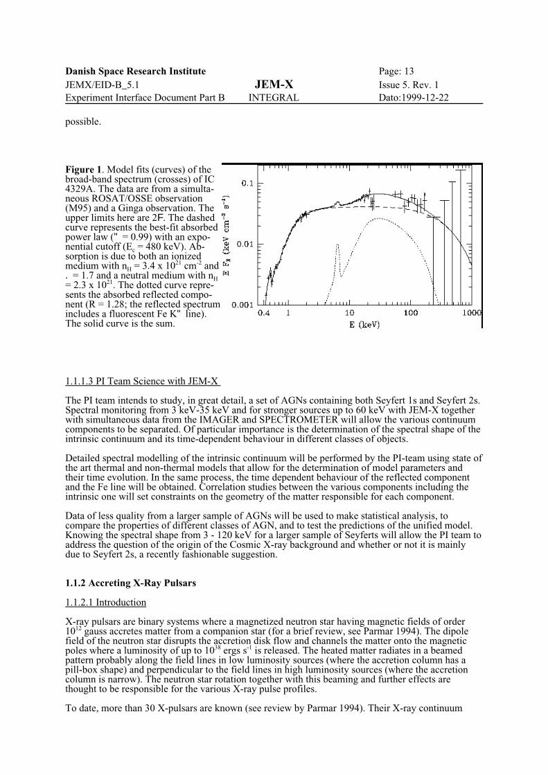
GINGA showed that the apparent X-ray power law spectra of Seyfert 1 galaxies, one of the most wellstudied class of AGNs, consist of two spectral components, one intrinsic power law of photon index-1.9 and one component, supposedly peaking at 30-40 keV arising from reflection (or reprocessing)of the intrinsic power law by cold opaque matter. The reflected component falls off both towardslower energies (due to photoelectric absorption) and towards higher energies (due to Comptondownscattering). Knowing the equivalent width (EW) of the fluorescent Fe-line at 6.4 keV in thereflected spectrum is of primary importance when making the two-component fit. Detailed X-ray togamma-ray spectra, 2-500 keV (with large spectral gaps) have been obtained for only two Seyfertgalaxies, IC 4329A (Madejski et al. 1995, see Figure 1) and NGC 4151 (Zdziarski et al. 1993,Maisack et al. 1993). They show different cutoff behavior for each source in the hard X-rays andgamma rays. For IC 4329A, simultaneous ROSAT and GRO OSSE data have been supplementedwith archival GINGA data. For NGC 4151 non-simultaneous GINGA and GRO OSSE data are used.It is clear from Figure 1 that using only the GRO OSSE data covering the range 60-500 keV does notallow the separation of the intrinsic component from the reflected one. Knowledge of the spectrumbelow about 10 keV, where the reflected component only makes a small contribution is required.Similarly, for NGC4151 the GRO OSSE data does not allow meaningful modelling using anyphysical process since the low energy power law below the break at 70 keV is not known. ForINTEGRAL, the 20 keV-10 MeV spectra from IMAGER must be supplemented with X-ray spectradown to and including the Fe line at 6.4 keV before any meaningful analysis of the Seyfert spectra is
Danish Space Research Institute Page: 13JEMX/EID-B_5.1 JEM-X Issue 5. Rev. 1Experiment Interface Document Part B INTEGRAL Dato:1999-12-22
possible.
Figure 1. Model fits (curves) of thebroad-band spectrum (crosses) of IC4329A. The data are from a simulta-neous ROSAT/OSSE observation(M95) and a Ginga observation. Theupper limits here are 2F. The dashedcurve represents the best-fit absorbedpower law (" = 0.99) with an expo-nential cutoff (Ec = 480 keV). Ab-sorption is due to both an ionizedmedium with nH = 3.4 x 1021 cm-2 and. = 1.7 and a neutral medium with nH= 2.3 x 10²¹. The dotted curve repre-sents the absorbed reflected compo-nent (R = 1.28; the reflected spectrumincludes a fluorescent Fe K" line).The solid curve is the sum.
1.1.1.3 PI Team Science with JEM-X
The PI team intends to study, in great detail, a set of AGNs containing both Seyfert 1s and Seyfert 2s.Spectral monitoring from 3 keV-35 keV and for stronger sources up to 60 keV with JEM-X togetherwith simultaneous data from the IMAGER and SPECTROMETER will allow the various continuumcomponents to be separated. Of particular importance is the determination of the spectral shape of theintrinsic continuum and its time-dependent behaviour in different classes of objects.
Detailed spectral modelling of the intrinsic continuum will be performed by the PI-team using state ofthe art thermal and non-thermal models that allow for the determination of model parameters andtheir time evolution. In the same process, the time dependent behaviour of the reflected componentand the Fe line will be obtained. Correlation studies between the various components including theintrinsic one will set constraints on the geometry of the matter responsible for each component.
Data of less quality from a larger sample of AGNs will be used to make statistical analysis, tocompare the properties of different classes of AGN, and to test the predictions of the unified model.Knowing the spectral shape from 3 - 120 keV for a larger sample of Seyferts will allow the PI team toaddress the question of the origin of the Cosmic X-ray background and whether or not it is mainlydue to Seyfert 2s, a recently fashionable suggestion.
1.1.2 Accreting X-Ray Pulsars
1.1.2.1 Introduction
X-ray pulsars are binary systems where a magnetized neutron star having magnetic fields of order1012 gauss accretes matter from a companion star (for a brief review, see Parmar 1994). The dipolefield of the neutron star disrupts the accretion disk flow and channels the matter onto the magneticpoles where a luminosity of up to 1038 ergs s-1 is released. The heated matter radiates in a beamedpattern probably along the field lines in low luminosity sources (where the accretion column has apill-box shape) and perpendicular to the field lines in high luminosity sources (where the accretioncolumn is narrow). The neutron star rotation together with this beaming and further effects arethought to be responsible for the various X-ray pulse profiles.
To date, more than 30 X-pulsars are known (see review by Parmar 1994). Their X-ray continuum

Danish Space Research Institute Page: 14JEMX/EID-B_5.1 JEM-X Issue 5. Rev. 1Experiment Interface Document Part B INTEGRAL Dato:1999-12-22
spectra are fitted with power laws having an (exponential) high energy cutoff at about 15 keV. Themost well studied object is Her X-1 (discovered in 1972) from which additional spectral features aredetected. Pre-eclipse dips are also observed and are thought to be caused by X-ray absorption inclouds near the point where the gas stream from the companion impacts on the disk. Detailed analysisof GINGA data (Choi et al. 1994) shows that during the absorption dips another (unpulsed) spectralcomponent becomes dominant caused, most likely, by the primary unobscured spectrum scattering inan optically thin corona. A fluorescent Fe line at 6.4 keV also shows the same pre-eclipse absorptionas the pulsed X-ray beam.
Early balloon experiments by Trümper et al. in 1977 (see Voges et al. 1982 for final analysis) showedthe existence of a shoulder in the spectral tail above the spectral cutoff in Her X-1. It was interpretedas a cyclotron feature either in emission at 52 keV or in absorption at 38 keV with the line centroidvarying sinusoidally during the pulsar period. This discovery confirmed the existence of 1012 gaussmagnetic fields in pulsars. The detailed analysis and spectral fitting by Soong et al. (1990) of thephase resolved spectroscopy in the 12-180 keV range, seen by HEAO 1 in 1978, favours theabsorption interpretation, as does most theoretical modelling. LAC on GINGA could be used up to 60keV in a low gain mode allowing the highest energy resolution studies (8% at 35 keV) of thecyclotron feature in Her X-1 to date (Mihara et al. 1990). Resolving the cyclotron (resonancescattering) feature allowed Mihara et al. to favour the absorption line interpretation with greatercertainty. GINGA increased the number of X-ray pulsars with known cyclotron features from 2 to 9(e.g review by Parmar 1994). The cutoff energies are typically around 15 keV with the cyclotron lineenergy between 20 and 40 keV.
CGRO BATSE with its continous monitoring was able to obtain the light curve of Her X-1 for the full35 day precession cycle in hard X-rays (15-70 keV), pulse profiles up to 200 KeV, and a phaseaveraged spectrum from 15 to 200 keV (Wilson et al. 1993). The quality of the spectral data weresuch that a power law of index -4.5 was an adequate fit with no need for any cyclotron feature. HerX-1 was also observed at three different times by CGRO OSSE (e.g. Kurfess et al. 1993). Althoughthe OSSE threshold at 40-50 keV does not allow the cyclotron line, to be observed, the OSSE datawill be analysed for the existence of higher cyclotron harmonic features.
1.1.2.2 Role of JEM-X
The hard X-ray emission from accreting X-ray pulsars will be observed by INTEGRAL's maininstruments. For the presently known sample of sources, the SPECTROMETER will be able to obtainphase resolved spectroscopy down to energies covering the cyclotron line energies (20-35 keV) aswell as to search for higher cyclotron harmonics. JEM-X will be a crucial supplement for theextension of the spectra to lower energies. It is of strong importance to have a full knowledge of thebehavior of different spectral components when analysing the phase dependent behavior of thecyclotron line features and of any hard X-ray and soft gamma-ray emission. 1.1.2.3 PI Team Science with JEM-X
The PI team intends to make phase resolved spectroscopy of most of the 9 X-ray pulsars known tohave cyclotron lines in order to better determine the spectral shapes as function of phase and to searchfor higher harmonic features and their phase dependent characteristics. Searches for cyclotronfeatures in additional X-ray pulsars will be also made. The lack of detection by Ginga may simply bedue to the limited energy range of LAC (even in the low gain mode).
Detailed theoretical interpretations will be made using both the phase dependent spectral shapes andthe pulse profiles in various energy ranges. The cyclotron features will be fitted with the standardanalytical shapes that have been sufficient thus far (or with improvements if necessary). The fits willbe interpreted in terms of recent radiative transfer models in highly magnetized media.
1.1.3 X-Ray Transients and Galactic Black Hole Candidates 1.1.3.1 Introduction
Several binary X-ray sources in our Galaxy (and nearby galaxies) show strong evidence that the X-ray emitting component is matter accreting into a black hole. Studies of these objects are veryimportant for establishing the existence of black holes of stellar mass and for probing the nearenvironment of a black hole where gravity is in the strong field limit. The clearest evidence that black

Danish Space Research Institute Page: 15JEMX/EID-B_5.1 JEM-X Issue 5. Rev. 1Experiment Interface Document Part B INTEGRAL Dato:1999-12-22
holes are involved is obtained first from X-ray observations of an unusual X-ray source and secondfrom optical measurements that the companion star is orbiting a mass larger than 3 Mà, this being themaximum accepted mass for a neutron star. The nature of the X-ray source is unusual in the sensethat there are no pulses attributable to the spin of a rigid body (such as a neutron star) - the X-ray lightcurve is often chaotic in form - and the spectrum is particularly hard, better fitting the expectation ofaccretion onto a body with no hard surface. Indeed, most of the objects detected by the instrumentHEAO-1 A4 at energies between 50 - 100 keV are considered to be Black Hole Candidates (BHC),the most famous of which is Cygnus X-1. The hard tail to the spectrum is remarkably similar in shapeto that observed from AGN.
Another notable feature of many BHC is that they show a number of separate intensity states; manyof them are transient, being undetectable in between outbursts that may last a few months and recurevery few decades.
To date almost a dozen good BHC have been identified. Some of those orbit massive stars and arepersistent in the sense that they can always be detected in X-rays e.g. Cyg X-1, LMC X-1 and LMCX-3. Some are X-ray transient BHC which orbit low mass stars e.g. A0620-00, GS2023+338 (V404Cyg) and GRS1124-68 (Nova Muscae). These last 2 are perhaps the best candidates of all since theirmass functions are 6.1 and 3.1 Mà respectively. There are also many other possible BHC (objectswhich have similar X-ray properties to the established candidates) which are difficult or currentlyimpossible to study optically because of obscuration due to their location in the Galactic Plane or nearthe Galactic Centre where they are highly obscured. Hard X-ray data from HEAO-1, Ginga, SIGMA and OSSE show that BHC have particularly hardspectra, or at least hard tails. In some cases, spectral features are seen which have been attributed toelectron-positron annihilation in the accreting material (Sunyaev et al., 1992; Goldwurm et al., 1992).Rapid variability, showing time lags between different spectral bands, is common. Broad iron lineand/or edge features are also common (Tanaka, 1992). Studies of these bright objects and comparisonwith AGN (which are much fainter and have much longer time scales) should reveal the emissionprocesses and behaviour of matter accreting into a black hole, and hopefully the nature of the holeitself. The transient BHC also show a much larger range of intensity in a single object compared withAGN, so providing an extra dimension for study.
1.1.3.2 Role of JEM-X
The hard spectrum of BHC will make them important targets for INTEGRAL. Possible annihilationfeatures and the spectral break seen around 100 keV or so, which is important for understanding theemission mechanisms, will make spectra of these objects a high priority. The whole X-ray/softgamma-ray spectrum is essential here and it is vital that JEM-X provides coverage down to 3 keV.
1.1.3.3 PI Team Science with JEM-X
The PI team intends to make detailed spectral and variability studies of the persistent BHC; CygnusX-1, LMC X-1 and LMC X-3, as well as some candidate BHC such as GX339-4. The transientsources are more difficult to schedule since they do not yet recur in a predictable manner. Neverthe-less we intend to study any that occur in the first years of operation of INTEGRAL.
The INTEGRAL core program including repeated surveys of the galactic plane and the central radianfavours this type of source monitoring and spectral analysis.
1.1.4 References
Antonucci, R., 1993 AREA, 31, 473."Unified models for AGN and Quasars"Choi, C. S. et al. 1994, Adj., 422, 799. "An Study of the Pre-Eclipse Dips of Her
X-1"Ghisellini, G., Haardt, F., and Matt, G. 1994, MARAS, 267, 743. "Obscuring torus and the spectrum of Seyfert Galaxies: a test for the unification model"George, I. M., and Fabian, A. C. 1991, MARAS, 249, 352. "X-ray reflection from cold matter in active galactic nuclei and X-ray binaries"Goldwurm et al., 1992, Adj. 389, L79. "Sigma/GRANT obs. of Nova Musca - Discovery of positron annihilation line"Kurfess, J. D. et al., 1993, in Compton Gamma Ray Observatory, Conf. Proc. 280, p 303Madejski, G. M. et al., 1995, Adj. 438, 672.

Danish Space Research Institute Page: 16JEMX/EID-B_5.1 JEM-X Issue 5. Rev. 1Experiment Interface Document Part B INTEGRAL Dato:1999-12-22
"Joint ROSAT-GRO observations of the X-ray bright Seyfert galaxy IC 4329A"Maisack, M. et al., 1993, Adj., 407, L61. "OSSE observations of NGC 4151"Matt, G., Fabian, A. C., and Ross, R. R., 1993a, MARAS, 262, 179. "Iron K-alpha lines from X-ray photo ionized accretion discs"Matt, G., Fabian, A. C., and Ross, R. R., 1993b, MARAS, 264, 839. "X-ray photo ionized accretion discs: UV and X-ray spectra and polarization"Marshall, F. E. et al., 1992, in Frontiers of Astroph, eds. Tanaka, and Koyama,, Tokyo: Universal Acad.Mihara, T. et al., 1990, Nature, 346, 250, "The cyclotron absorption feature in Hercules X-1"Mushotzky, R. F., Done, C., and Pounds, K. A., 1993, AREA, 31, 717. "X-ray spectra and time variability of active galactic nuclei"Parmar, A. 1994, in The Evolution of X-Ray Binaries, AIP Conf. Proc. 308, p 415.Pounds, K.A. et al., 1990, Nature, 344, 132, "X-ray reflection from cold matter in AGN"Ross, R. R. and Fabian, A. C., 1993, MARAS, 261, 74. "The effects of photoionization on X-ray reflection spectra in active galactic nuclei"Soong, Y. et al., 1990, Adj., 348, 641. "Spectral behavior of Her X-1 - long-term variability and pulse phase spectroscopy"Sunyaev, R., et al., 1992, Adj., 389, L75. "X-ray nova in Musca - Hard X-ray source with narrow annihilation line"Tanaka, Y., 1992, Proc. Ginga Mem. Symp., ISAS, p. 19.Voges, W. et al., 1982, Adj., 263, 803. "Cyclotron lines in the X-ray spectrum of Her X-1"Weaver, K. A. et al., 1992, Adj., 401, L11. "Broad Band X-Ray Telescope observations of NGC 4151 - Iron line diagnostics"Wilson, R. B. et al. 1993, in Compton Gamma Ray Observatory, AIP Conf. Proc. 280, p 291.Yaqoob, T. et al., 1993, Adj., 416, L5. "The FeK line as a probe of beamed emission in AGN"Zdziarski, A. A., Lightman, A. P., and Maciolek-Niedzwiecki, A., 1993, Adj., 414, L93. "Acceleration efficiency in nonthermal sources and the soft gamma rays from NGC 4151"

Danish Space Research Institute Page: 17JEMX/EID-B_5.1 JEM-X Issue 5. Rev. 1Experiment Interface Document Part B INTEGRAL Dato:1999-12-22
1We use the term “fully illuminated field” here rather than the more conventional“fully coded field” because the JEM-X detector does not cover, even for an on-axis source,the complete code pattern of the mask.
Active mask diameter 535 mm
Active detector diameter 250 mm
Distance from mask to detectorentrance window
3398 mm
Energy range 3 - 35 keV Primary range35-60 keV First extension1
60 - 100 keV Second extension2
Energy resolution )E/E = 0.47 (E/1 keV)-½
Angular resolution 3 arcmin
Field of view (diameter) Fully illuminated 4.8EPartially illuminated3 7.5EZero response 13.2E
Relative point source locationerror
< 30 arcsec (10F source)
Narrow line sensitivity(isolated source)
2.5 10-4 photons cm-2 s-1 @ 6 keV 2.5 10-4 photons cm-2 s-1 @ 30 keV for a 5F line detection in a 105 s observation
Continuum sensitivity (isolated source)
7 10-6 photons cm-2 s-1 keV-1 @ 6 keV for a 3F cont. detection in a 106 s observation
Timing accuracy 122 µs (1/8192 s)
1) JEM-X will operate in this range but the quantum efficiency is reduced.2) Photons can still be registered in this range but the imaging capabilities are reduced sincethe mask is not completely opaque at these energies.3)At this angle the sensitivity is reduced by a factor 2 relative to the on-axis sensitivity.
Table 1: JEM-X Specifications
1.2 Scientific Performance Summary
The key properties for the scientific capabilities are: Field of view, source detection sensitivity,angular resolution, point source location accuracy, and spectral resolution as listed in Table 1.
The Field of View has been dimensioned to allow the 2E dithering steps required by the gamma-rayinstruments. A source, offset 2E with respect to the instrument axis, will still be inside the fullyilluminated1 field of view .

Danish Space Research Institute Page: 18JEMX/EID-B_5.1 JEM-X Issue 5. Rev. 1Experiment Interface Document Part B INTEGRAL Dato:1999-12-22
1.3 Instrument description
1.3.1 Measurement principle
The JEM-X instrument is based on the same measurement principle as the two gamma-ray instru-ments on INTEGRAL: sky imaging using a Coded Aperture Mask. An imaging X-ray detectorobserves the sky through a perforated mask, the hole pattern on the mask is designed to assure thateach source within the Field-of-View can be recognized through its shadowgram. The dimensions ofthe holes in the mask and the separation between the mask and the detector determines the angularresolution of the instrument, in the case of JEM-X the angular resolution is 3 arcminutes, which is thebest of the three high-energy instruments on INTEGRAL.
1.3.1.1 Functional description
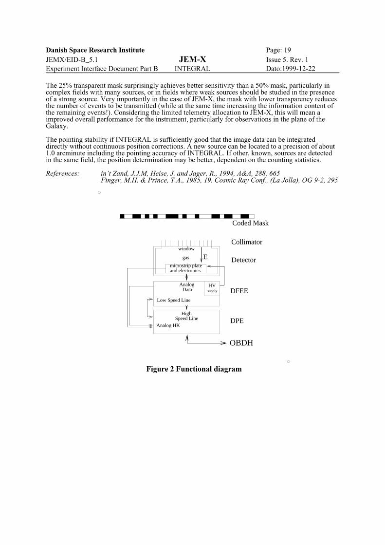
The description below follows the diagram in Fig. 2 from top to bottom. The cosmic X-ray photonsenters the JEM-X instrument through the holes in the coded mask situated 3.4 m above the detectorentrance window. Inside the detector the photons are absorbed in the xenon gas, and resultingionization cloud is amplified and detected on the Micro strip plate. The energy of the incomingphoton and its position can be determined from the electrical signals induced on the micro strips.
Thanks to the hole pattern in the mask the photons originating from a particular point source on thesky will produce a unique pattern of illuminated spots on the detector. Sources in different positionson the sky will produce different spot patterns on the detector. These patterns can later be disentan-gled and the source positions and strengths can be determined from the complex image.
The Field of View of JEM-X is defined by a collimator placed on top of the detector entrancewindow. The collimator has an acceptance angle of 6.6E at zero response. This angle matches theangle defined by the mask-detector combination. The collimator is important for reducing the countrate caused by the cosmic diffuse X-ray background. However, the presence of the collimatorunavoidably also mean that sources near the edge of the Field-of-View will be attenuated with respectto on-axis sources.
The photon absorption process is mostly dominated by the photo-electric absorption of the photon inthe xenon gas in the detector. This process causes an electron to be emitted from the struck Xe-atom.The emitted electron will ionize other atoms along its track and thus create a cloud of electrons. Anelectric field between the entrance window and the Micro strip sensor plate, will cause the electroncloud to drift towards the Micro strip plate. When it is sufficiently close to one of the individualanode strips the electric field becomes so strong that an avalanche of ionizations is created and asignificant electric charge is picked up on the strip as an electric impulse.
A capacitive read-out system is used on the Micro strip plate for determination of the avalancheposition. The signals from the read-out chains delivered to the Digital Front End Electronics (DFEE)for calculation of the position of the interaction and for rejection of unwanted events. The majority ofthe background events will be due to cosmic ray or Solar energetic particles, but some of the highenergy photons are absorbed through a two stage process, which leaves two spatially separated chargeclouds in the gas. The position of the first interaction for these events is ambiguous and they will berejected by the electronics.
The event data is finally passed to the Digital Processing Electronics (DPE) which formats the data for the telemetry. The full set of parameters for an event consists of arrival time, position in thedetector (x and y), and pulse-height (proportional to energy). When observing source fields withintegrated source fluxes exceeding about 750 mCrab (about 100 counts per s) the telemetry allocation will be fully used, and some data must be rejected.
The Mask is based on a Hexagonal Uniformly Redundant Array (HURA) as described by Finger andPrince (1985), however for JEM-X a pattern with only 25% open area have been chosen, based on aso-called "Bi-quadratic Difference Residue Set" corresponding to the prime number 22501 (see in'tZand et al, 1994). In order to obtain an angular resolution of 3 arcminutes the dimension of thehexagonal cells have been chosen as 3.3 mm. measured across the hexagon faces. The total number ofelements in the mask will be about 23300, so a slight repetition of the pattern will be needed at theedge of the mask.
Danish Space Research Institute Page: 19JEMX/EID-B_5.1 JEM-X Issue 5. Rev. 1Experiment Interface Document Part B INTEGRAL Dato:1999-12-22
microstrip plate
gas
window
and electronics
HVsupply
E
Analog HK
AnalogData
HighSpeed Line
Coded Mask
Collimator
Detector
DFEE
DPE
OBDH
Low Speed Line
Figure 2 Functional diagram
The 25% transparent mask surprisingly achieves better sensitivity than a 50% mask, particularly incomplex fields with many sources, or in fields where weak sources should be studied in the presenceof a strong source. Very importantly in the case of JEM-X, the mask with lower transparency reducesthe number of events to be transmitted (while at the same time increasing the information content ofthe remaining events!). Considering the limited telemetry allocation to JEM-X, this will mean a improved overall performance for the instrument, particularly for observations in the plane of theGalaxy.
The pointing stability if INTEGRAL is sufficiently good that the image data can be integrateddirectly without continuous position corrections. A new source can be located to a precision of about1.0 arcminute including the pointing accuracy of INTEGRAL. If other, known, sources are detectedin the same field, the position determination may be better, dependent on the counting statistics.
References: in’t Zand, J.J.M, Heise, J. and Jager, R., 1994, A&A, 288, 665Finger, M.H. & Prince, T.A., 1985, 19. Cosmic Ray Conf., (La Jolla), OG 9-2, 295

Danish Space Research Institute Page: 20JEMX/EID-B_5.1 JEM-X Issue 5. Rev. 1Experiment Interface Document Part B INTEGRAL Dato:1999-12-22
1.3.1.2 Observation strategy
When observing a source field INTEGRAL will normally execute a sequence of sub-exposures withslight changes of the satellite pointing in between. This “dithering” improves the imaging for thegamma-ray instruments. The duration of the sub-exposures will be about 1000 seconds during theGalactic Plane Scans and about 1800 s during all other observations..
1.3.1.3 On board calibration
To calibrate the energy response of the JEM-X detectors a calibration system consisting of fourradioactive sources is embedded in the detector collimators. These sources will permit to monitor thegas gain of the detector continously.
The detector position determination can be calibrated in-flight by observing a strong point-like sourcesuch as the Crab. The position determination precision in the detector is best at energies between 4and 15 keV. The count rate of the Crab Nebula in this interval is about 150 cts s-1. There are about1300 open cells positions projected from the mask to the detector. In a 1000 s observation of the Crabwe will therefore get about 120 source counts in each illuminated spot on the detector and we maycompare with the mask pattern to verify the position resolution.

Danish Space Research Institute Page: 21JEMX/EID-B_5.1 JEM-X Issue 5. Rev. 1Experiment Interface Document Part B INTEGRAL Dato:1999-12-22
1.3.2 Hardware description
The JEM-X monitor consists of two coaligned, identical telescope units. A single JEM-X unitcomprises 3 major subsystems: the detector, the associated electronics and the coded mask.
1.3.2.1 Detector
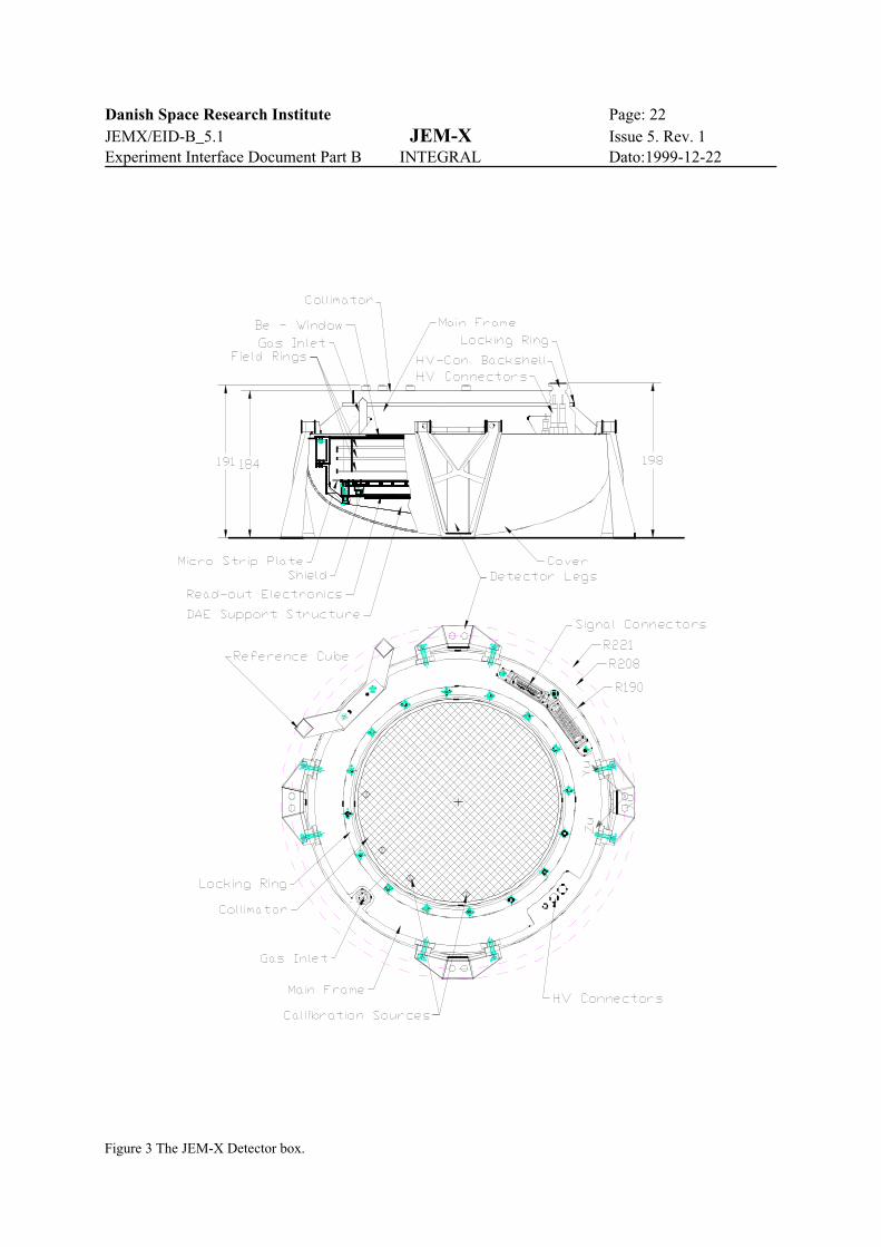
The JEM-X detector is shown Figure 3. It is a Micro strip Gas Chamber with a sensitive area of about500 cm2. The detector consists of the following modules: the detector vessel, the collimator, the X-raywindow , the sensor package with the Detector Analog Electronics (DAE) and the calibration sources.The gas inside the detector is a mixture of xenon and methane at 5 bar pressure.
The diameter of the detector window is 250 mm, the height of the detector front window above thereference plane defined in the MICD is 127 mm.
1.3.2.1.1 Detector Vessel
The detector body is made of stainless steel and consists of two parts, the main-frame and the coverwhich are joined together by electron beam welding. There are no gaskets.
The cover is formed from 2 mm thick stainless steel plate. The shape of the cover is similar to that ofthe cap for a pressure vessel.
The main-frame is a cone shaped ring with a circular flange in the middle for mounting the collima-tor. The elctrical connectors, the high voltage feed throughs and the gas filling tube are welded to thismain-frame. All internal structures also mounts to the main-frame. The internal structure consists oftwo sets of vertical studs and a spider structure. The field forming rings are fixed on one set of studsand the MS-sensor package and the spider structure is mounted on the other set of studs. The spiderstructure carries the Detector Analog Electronics (DAE).
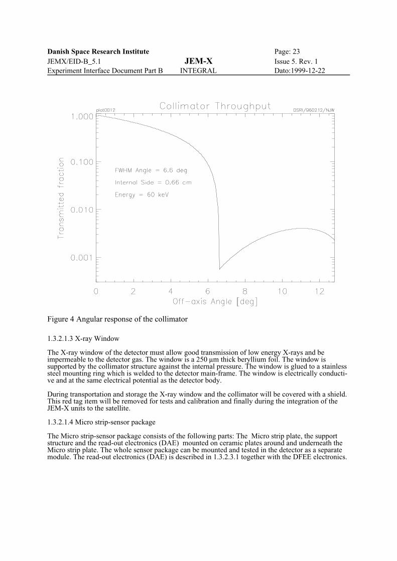
1.3.2.1.2 Collimator
The collimator has a dual role, it acts as a support for the thin X-ray window against the internalpressure of the detector, and it limits the field of view (FOV). The full-width-at-half-maximum of thecollimator FOV is tailored to have the same zero response as that of the detector-mask combination(6.6 deg). This is the best match to maximize the instrument signal-to-noise ratio. The collimator cellgeometry is chosen to be square. This geometry is less expensive than a hexagonal one and it is fullycompatible with the hexagonal cell geometry of the mask as verified by numerical simulations. Thematerial chosen for the core of the collimator is molybdenum with a thickness of 180 micrometers.This allows to obtain a close to zero collimator response for incident angles greater than 6.6 deg. TheK-fluorescence photons produced by the molybdenum could contribute to the detector background.To reduce this contribution the molybdenum will be covered by 35 micrometer copper from bothsides of the cell walls. Finally a 100 micrometer aluminum layer will be added on top to absorb the 9keV K-fluorescence photons of copper.
The manufacturing process of the collimator cells has been defined after a test campaign performed toverify the dynamical strength of the design. The cells will be made of crossed slats of Molybdenumcovered on both sides with a bilayer of Copper and Aluminium. The Copper is fixed to the Molybde-num plates with a double side cladding process. The Aluminum layer is fixed on both sides by adiffusion bonding process. The single cells are stiffened with an eutectic Zn5Al brazing. The brazingprocess has been tested. The cell structure is contained in an external ring of Molybdenum which isbrazed to the cell structure with the above eutectic. Collimator subscale elements have been assembled and the qualification tests to verify their strength and their life time are now in progress.The internal side of each cell is 6.6 mm and its height is 57.0 mm. The cell assembly is circular with adiameter of 250 mm corresponding to the beryllium window diameter. An external ring of 3 mmthick Molybdenum supports the collimator cell assembly and has the role to interface with thedetector frame.
Figure 4 shows the angular response of the collimator at 60 keV
Danish Space Research Institute Page: 22JEMX/EID-B_5.1 JEM-X Issue 5. Rev. 1Experiment Interface Document Part B INTEGRAL Dato:1999-12-22
Figure 3 The JEM-X Detector box.
Danish Space Research Institute Page: 23JEMX/EID-B_5.1 JEM-X Issue 5. Rev. 1Experiment Interface Document Part B INTEGRAL Dato:1999-12-22
Figure 4 Angular response of the collimator
1.3.2.1.3 X-ray Window
The X-ray window of the detector must allow good transmission of low energy X-rays and beimpermeable to the detector gas. The window is a 250 µm thick beryllium foil. The window issupported by the collimator structure against the internal pressure. The window is glued to a stainlesssteel mounting ring which is welded to the detector main-frame. The window is electrically conducti-ve and at the same electrical potential as the detector body.
During transportation and storage the X-ray window and the collimator will be covered with a shield.This red tag item will be removed for tests and calibration and finally during the integration of theJEM-X units to the satellite.
1.3.2.1.4 Micro strip-sensor package
The Micro strip-sensor package consists of the following parts: The Micro strip plate, the supportstructure and the read-out electronics (DAE) mounted on ceramic plates around and underneath theMicro strip plate. The whole sensor package can be mounted and tested in the detector as a separatemodule. The read-out electronics (DAE) is described in 1.3.2.3.1 together with the DFEE electronics.
Danish Space Research Institute Page: 24JEMX/EID-B_5.1 JEM-X Issue 5. Rev. 1Experiment Interface Document Part B INTEGRAL Dato:1999-12-22
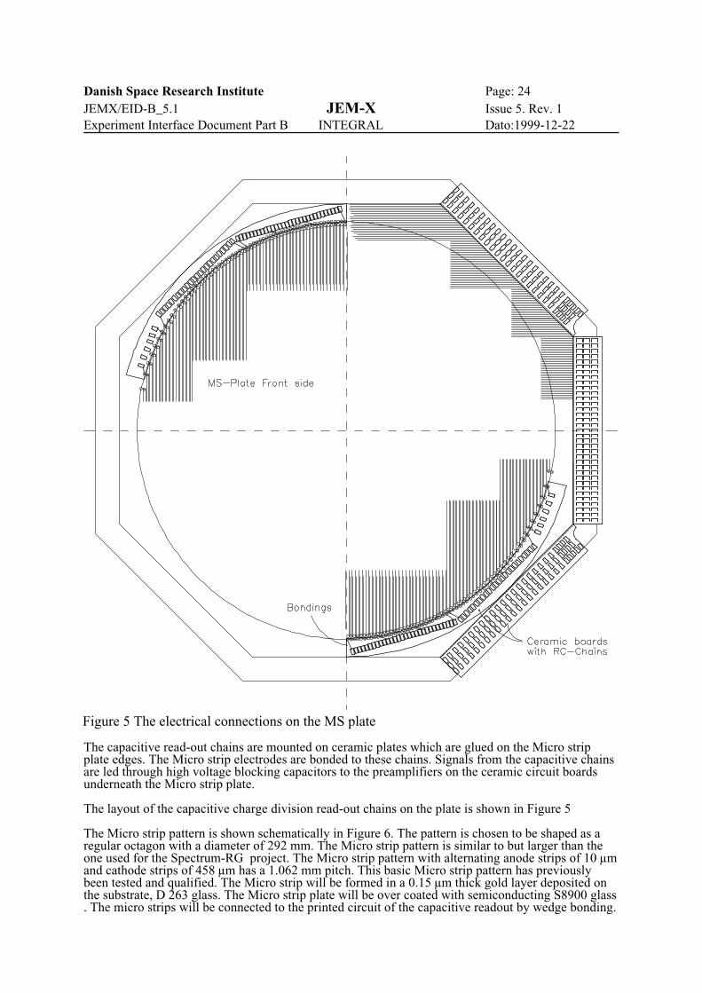
Figure 5 The electrical connections on the MS plate
The capacitive read-out chains are mounted on ceramic plates which are glued on the Micro strip plate edges. The Micro strip electrodes are bonded to these chains. Signals from the capacitive chainsare led through high voltage blocking capacitors to the preamplifiers on the ceramic circuit boardsunderneath the Micro strip plate.
The layout of the capacitive charge division read-out chains on the plate is shown in Figure 5
The Micro strip pattern is shown schematically in Figure 6. The pattern is chosen to be shaped as aregular octagon with a diameter of 292 mm. The Micro strip pattern is similar to but larger than theone used for the Spectrum-RG project. The Micro strip pattern with alternating anode strips of 10 µmand cathode strips of 458 µm has a 1.062 mm pitch. This basic Micro strip pattern has previouslybeen tested and qualified. The Micro strip will be formed in a 0.15 µm thick gold layer deposited onthe substrate, D 263 glass. The Micro strip plate will be over coated with semiconducting S8900 glass. The micro strips will be connected to the printed circuit of the capacitive readout by wedge bonding.
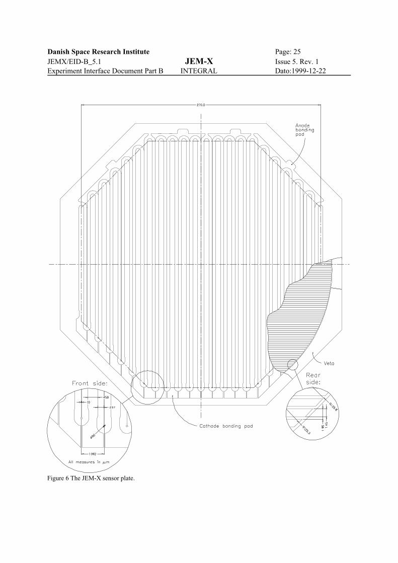
Danish Space Research Institute Page: 25JEMX/EID-B_5.1 JEM-X Issue 5. Rev. 1Experiment Interface Document Part B INTEGRAL Dato:1999-12-22
Figure 6 The JEM-X sensor plate.

Danish Space Research Institute Page: 26JEMX/EID-B_5.1 JEM-X Issue 5. Rev. 1Experiment Interface Document Part B INTEGRAL Dato:1999-12-22
The anode strips are connected into four groups, the signals from these are used for event triggering,energy determination and for pulse shape analysis. The cathode strips are read out using thecapacitive charge division chains. The position of the avalanche in the direction perpendicular to theMicro strip pattern, the X-axis, are determined from the centroid of the avalanche charge. The Y-coordinate for an event are obtained from an orthogonal set of pickup electrodes (also shownin Figure 6) deposited on the rear surface. These electrodes are arranged on a 2 mm pitch and are alsoread out by capacitive chains. For the 0.9 mm thick substrate, the pickup signal will be 18% of theavalanche charge. This is sufficient to achieve the required position resolution.
The rear strips are surrounded by a veto-electrode which is used to suppress events caused bycharged particles entering through the sides of the detector.
1.3.2.1.5 Calibration Sources
Four calibration sources are integrated with the collimator.
The on board calibration system consists of the Fixed Radioactive Sources System.This system iscomposed of four 1.0 µCi, highly collimated radioactive Cd109 sources.. The sources are locatedwithin four cells of the JEM-X collimator. The photons from the sources will produce spots of 4 mm2
in each of the four anode groups on the microstrip plate. The Cd10 9 sources will be collimated usingAu and Mo absorbers and will be screwed into Al housings which will be glued in their respectivecollimator cells. Each Cd109 source emits 22 and 88 keV photons and moreover they produce Nifluorescence photons (7.5, 8.2 keV) from the source support Ni windows. The expected count ratesare: 8 counts/s at 7.5 keV, 4 counts/s at 22 keV and 0.04 counts/s produced by the 88 keV photons.The latter events will only be suitable for long term checks of the detector calibration.
1.3.2.2 Coded Mask
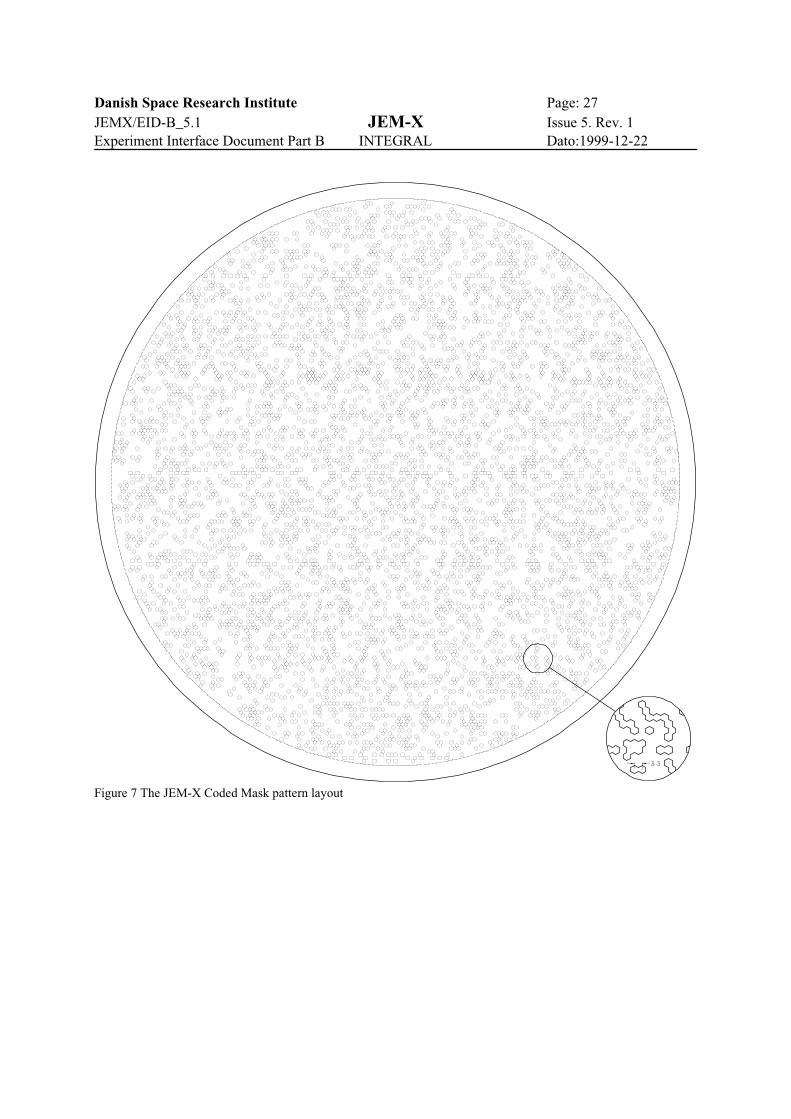
The coded mask is a 0.5 mm thick tungsten plate. This thickness achieves the required opacities of99.9% at 35 keV and 95% at 60 keV. The manufacturing technique chosen for the hole pattern isspark erosion using a wire electrode.The height of the mask above the detector plane is about 3.4 m (see table 1). A peripheral titaniumring provides pretension and structural support to the coded mask . The ring also acts as themechanical interface with the INTEGRAL Payload Module, by means of 12 equally spaced bolts. .The diameter of the mask coded area is 535mm. The mask elements will be hexagonal, and their sizeis 3.3 mm center-to-center.
The combination of the mask height and the mask element dimension means that the angularresolution of the instrument is 3.35 arcmin.
In order to withstand a 12 g axial and a 12 g lateral acceleration, and to have a fundamental resonantfrequency above 60 Hz (axial) and 120 Hz (lateral), a reinforcement structure in titanium will supportthe mask. The reinforcement structure (exo-skeleton) has three internal rings connected by radial ribs.The loss of transparency due to the exo-skeleton is less than 2 % and the additional mass is about 1.7kg.
Figure 7 is an illustration of the JEM-X coded mask pattern layout (mechanical interface not shown).The order of the basic pattern is 22501 (see section 1.3.1). The number of open cells in the mask is5844.
Danish Space Research Institute Page: 27JEMX/EID-B_5.1 JEM-X Issue 5. Rev. 1Experiment Interface Document Part B INTEGRAL Dato:1999-12-22
Figure 7 The JEM-X Coded Mask pattern layout
Danish Space Research Institute Page: 28JEMX/EID-B_5.1 JEM-X Issue 5. Rev. 1Experiment Interface Document Part B INTEGRAL Dato:1999-12-22
HV Filter
DV 0-3 kV
VC 3 kV
BackplaneCathodeAnodeVetoFieldring
20 BackplaneSegments Y
11 CathodeSegments X 1 Veto Ring 4 Anode Segments
Micro Strip Plate
Power 20 Backplane+11 Cathode
VetoChannel
Anode4 Channels
Cal
Connector J/P 15Connector J/P 14
+12V
-12V
PressureSensors
TemperatureSensors
20 Backplane+ 11 Cathode Veto Anode
AnodeRedundant Level Timing
High Voltage
Low Voltage
File: apollo\fa\doc\jemx\eid-b\DAEBlk.wmf
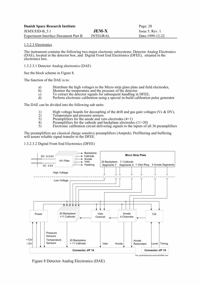
Figure 8 Detector Analog Electronics (DAE)
1.3.2.3 Electronics
The instrument contains the following two major electronic subsystems: Detector Analog Electronics(DAE), located in the detector box, and Digital Front End Electronics (DFEE), situated in theelectronics box.
1.3.2.3.1 Detector Analog electronics (DAE)
See the block scheme in Figure 8.
The function of the DAE is to:
a) Distribute the high voltages to the Micro strip glass plate and field electrodes,b) Monitor the temperature and the pressure of the detector.c) To extract the detector signals for subsequent handling in DFEE,d) Perform electronic calibration using a special in-build calibration pulse generator
The DAE can be divided into the following sub units:
1) High voltage boards for decoupling of the drift and gas gain voltages (Vc & DV),2) Temperature and pressure sensors.3) Preamplifiers for the anode and veto electrodes (4+1)4) Preamplifiers for the cathode and backplane electrodes (11+20) 5) Electronic calibration circuit delivering signals to the inputs of all 36 preamplifiers
The preamplifiers are classical charge sensitive preamplifiers (Amptek). Prefiltering and bufferingwill assure reliable signal transfer to the DFEE.
1.3.2.3.2 Digital Front End Electronics (DFEE)

Danish Space Research Institute Page: 29JEMX/EID-B_5.1 JEM-X Issue 5. Rev. 1Experiment Interface Document Part B INTEGRAL Dato:1999-12-22
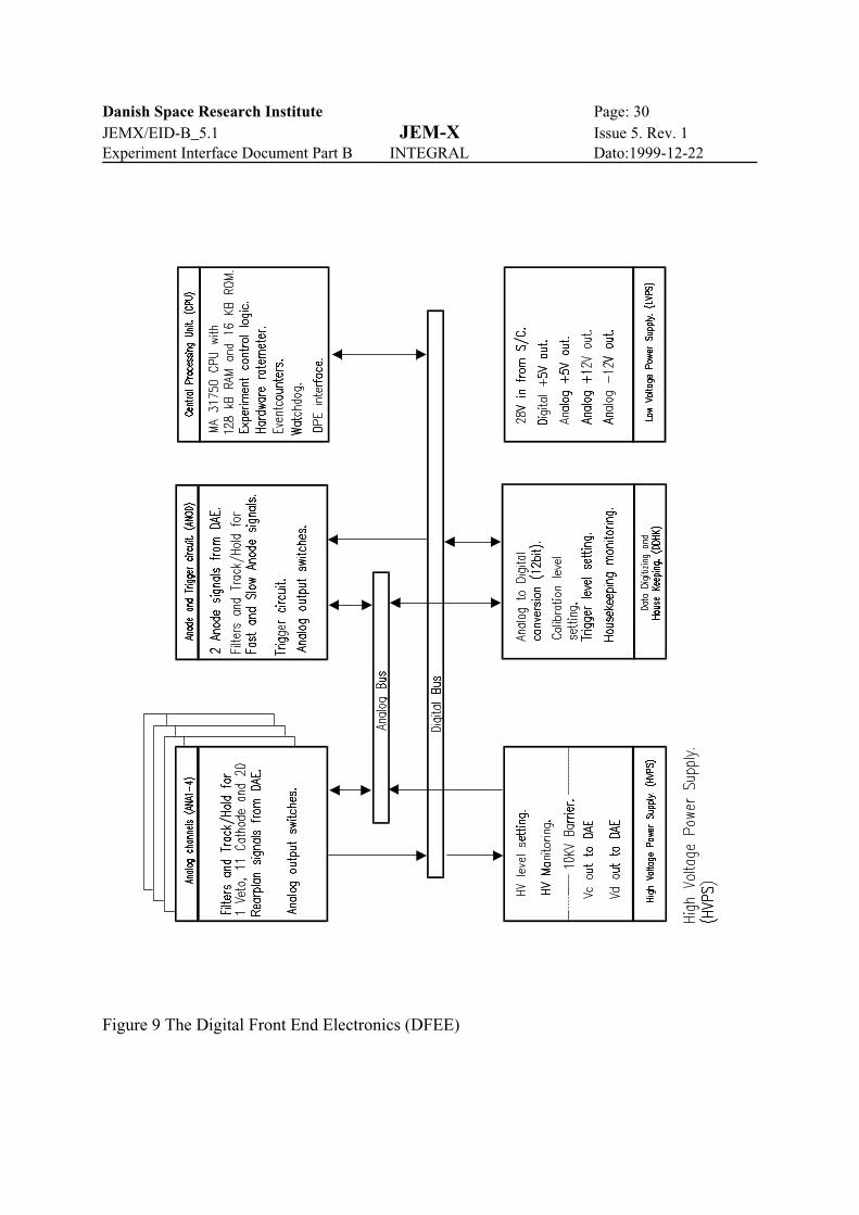
The block scheme is shown in Figure 9:
The function of the DFEE is to:
1) Generate main event trigger, based on the anode (Energy) signal,2) Amplify, filter and peak detect the detector signals,3) Digitize the signals4) Validate the events (for background rejection), 5) Calculate position and energy of valid events,6) Communicate with the DPE,7) Generate and control the high voltages Vc & DV.8) Adjust the discriminator level for the main event trigger,9) Convert the primary 27V to the instrument voltages and distribute them,10) Perform housekeeping monitoring of voltages, currents and temperature,
The DFEE can be divided into the following subunits:
1) Anode HF and LF filter amplifiers and peak detectors,2) Anode discriminator,3) Cathode and rear side filter amplifiers, peak detectors,4) Fast 12 bit ADC reading all 34 peak detector channels,5) 16 bit MA31750 processor controlling the high speed instrument bus,6) Interrupt controller ,Watchdog, Memory (RAM and PROM),7) Serial RS 422 interfaces to the DPE,8) Housekeeping (Voltages,Temperatures,Pressures) and instrument control
(high voltages settings, electronic calibration control, discriminator level),9) Low Voltage converters,10) High Voltage converter,
The MA31750 processor controls the reading of the analog bus and communicates with all functionalunits via the instrument bus. It performs all event validation (position footprint, centroid finding,anode, energy and signal risetime acceptance.
A hard-wired ratemeter circuit will monitor the pulse rate of the anode signals. The circuit will switchoff the high voltages in case of very high rates. The high voltages can be switched on again bycommand from the ground. This ratemeter will operate independently of the processor, i.e. it will befunctional even if the processor is stalled.
Danish Space Research Institute Page: 30JEMX/EID-B_5.1 JEM-X Issue 5. Rev. 1Experiment Interface Document Part B INTEGRAL Dato:1999-12-22
Figure 9 The Digital Front End Electronics (DFEE)

Danish Space Research Institute Page: 31JEMX/EID-B_5.1 JEM-X Issue 5. Rev. 1Experiment Interface Document Part B INTEGRAL Dato:1999-12-22

Danish Space Research Institute Page: 32JEMX/EID-B_5.1 JEM-X Issue 5. Rev. 1Experiment Interface Document Part B INTEGRAL Dato:1999-12-22
1.3.3 Software description
The JEM-X on-board software will be distributed between the DFEE processor and the DPE.
The DFEE processor will interface to the detector electronics on one side and via the fast serial line tothe DPE on the other. The software in the DFEE processor will perform the following tasks:
- Detector read-out control- Single event evaluation- Background rejection- Event buffering and transmission to DPE- Hardware parameter control.
The DPE will interface to the DFEE processor on the one side and to the S/C OBDH on the other. Thesoftware supplied by the PI-team will perform the following tasks:
- Data reception from the front-end processor- Data compression and TM-buffer build-up- Housekeeping data acquisition- Telemetry and Telecommand communication.
The on-board software will be developed according to ESA PSS-05-0. The DPE software will bewritten in ADA and the DFEE software will be written in assembler to achieve the required perfor-mance in terms of execution speed. As a consequence, the amount of software functionality imple-mented in the DFEE will be kept to a minimum.

Danish Space Research Institute Page: 33JEMX/EID-B_5.1 JEM-X Issue 5. Rev. 1Experiment Interface Document Part B INTEGRAL Dato:1999-12-22
OFF
IASW Standby
IASW Active
G,T G,T
G,T G,T
G,T G,TState Changing Commands
A Automatic Transition
B Broadcast Packet
G Ground Telecommand
T Time TaggedTelecommand
SafeMemory
Patch/Dump
Setup
Calibration DiagnosticData Taking
G
G,A,B
G
G,A,B
G,B,TG,T,B
G,B,TG,T,B
G,T
G,T,B
OFF
DPE STATES
DFEE STATES
Figure 10: JEM-X State Diagram
1.4 Instrument operations
The two JEM-X instruments are operated independently. Housekeeping packets are generated in allstates where the DPE is ON. Science data will only be generated when the DFEE is on, however, alarge data buffer exists in the DPE and therefore Science-TM packets may be generated for some timeafter the DFEE is switched off. Special Science TM-formats are used in the CALIBRATION andDIAGNOSTIC states.
The following figure illustrates the DPE and DFEE operational states as well as the type of com-mands that may cause a change between states. The instrument operations are described in the UserManual.

Danish Space Research Institute Page: 34JEMX/EID-B_5.1 JEM-X Issue 5. Rev. 1Experiment Interface Document Part B INTEGRAL Dato:1999-12-22

Danish Space Research Institute Page: 35JEMX/EID-B_5.1 JEM-X Issue 5. Rev. 1Experiment Interface Document Part B INTEGRAL Dato:1999-12-22
2 COMPLIANCE OF INSTRUMENT DESIGN2.1 Compliance with Spacecraft configuration
2.1.1 Accomodation constraint
In general the JEM-X accommodation constraints comply with the spacecraft baseline configuration,EID-A sec. 2.4.
The following points should be observed:
1. The field of view of each JEM-X unit must be free of obscuring objects. The field of view isa cone with a half opening angle of 6.6E. The apex of the cone is located on the instrumentaxis, 2257 mm below the mask mounting surface. (The opening of the cone is determinedby the detector collimator, the diameter of the cone at the mask level is defined by thediameter of the coded mask).
2. The mounting of the JEM-X detectors must ensure that the operating in-orbit temperaturestays within the limits given in section 3.3.1. Temperature change rates should not exceed10EC per hour during operation.
3. The JEM-X detectors must be shielded against radiation from calibration sources located inother instruments.
2.1.2 FOV sensors/radiation
The zero response field of view of JEM-X is 13.2E (18.6E across the collimator diagonal).
The charged particle radiation, from the cosmic radiation and from the Sun, is the dominant source ofbackground for JEM-X. About 1700 counts/s are expected from this source. The cosmic diffuse X-rayflux will add another 20 counts/s. To this must be added the flux from any X-ray source in the FOV.
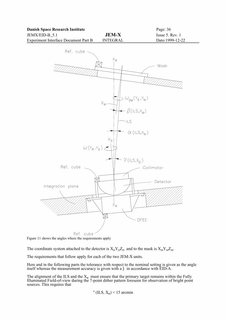
2.1.3 Alignment requirements
Figure 11 shows the angles of importance in the alignment of JEM-X on INTEGRAL. The referencesystem XRYRZR is defined by the AOCS with the axis XR / STR-LOS of the startracker. The opticalaxis or Instrument Line-of-Sight (ILS) of JEM-X is defined as the axis through the centers of themask and the detector. The detector is equipped with a collimator with a direction (XC) where thethroughput has a maximum. Ideally these three axes should coincide.
Danish Space Research Institute Page: 36JEMX/EID-B_5.1 JEM-X Issue 5. Rev. 1Experiment Interface Document Part B INTEGRAL Dato:1999-12-22
Figure 11 shows the angles where the requirements apply
The coordinate system attached to the detector is XDYDZD and to the mask is XMYMZM.
The requirements that follow apply for each of the two JEM-X units.
Here and in the following parts the tolerance with respect to the nominal setting is given as the angleitself whereas the measurement accuracy is given with a ) in accordance with EID-A.
The alignment of the ILS and the XR must ensure that the primary target remains within the FullyIlluminated Field-of-view during the 7-point dither pattern foreseen for observation of bright pointsources. This requires that
"(ILS, XR) < 15 arcmin
Danish Space Research Institute Page: 37JEMX/EID-B_5.1 JEM-X Issue 5. Rev. 1Experiment Interface Document Part B INTEGRAL Dato:1999-12-22
)"(ILS, XR) < 1 arcmin (goal)
)" is directly related to the precision of the determination of a source position. In-flight calibrationwill give a better determination of ".
XD, XM, and ILS must be aligned to such a degree that the apparent shortening of pixels due to theprojection effect is smaller than the error of the position determination in the detector. On the otherhand the image reconstruction can take into account an apparent distortion of the mask hole shape.
The collimator transmission, T, as a function of the incoming direction with respect to the collimatoraxis, XC, has a triangular shape. The JEM-X collimator system will be designed to have zero responseat the same angle where the mask-detector combination have zero response. In order to make an X-ray flux determination to a precision of 1 %, the direction of the XC must be known to a precision of 5arcmin relative to the source direction. The direction of the optical reference cube relative to the XCwill be obtained from laboratory measurements.
There will be two optical reference cubes on the top of the detector and one on top of the mask asindicated on Figure 11 and on the ICD. The angle between XD and ILS is ((ILS,XD), the anglebetween XM and ILS is $(ILS,XM), and the condition mentioned above leads to
((ILS,XD) < 40 arcmin
)((ILS,XD) < 5 arcmin
$(ILS,XM) < 75 arcmin
)$(ILS,XM) < 15 arcmin
This ensures that for deviations in opposite directions, the projected position errors on the detector willbe no larger than 0.5 mm and will be known to 0.1 mm. A change in ((ILS,XD) changes T, the collimatortransmission coefficient, of a source at the nominal pointing direction. T should be known to a precisionof 1% and, therefore, )((ILS,XD) must be less than 5 arcmin. ((ILS,XD) itself is limited to 40 arcmin toensure that T is greater than 90% of its maximum for an on-axis source.
With regard to the rotational precision of the detector around the reference axis XR a similar conditionshould be met
T(YR,YD) < 30 arcmin
)T(YR,YD) < 5 arcmin
In addition, the rotation of the mask relative to the detector has influence not only on the source positiondetermination but also on the source detection since an error in this angle will lead to erroneousassignment of photons to an allowed or forbidden region on the detector, when a particular point on thesky is analyzed.
Thus,
TDM(YD,YM) < 30 arcmin
)TDM(YD,YM) < 1 arcmin (goal)
2.1.4 Max distance between units
N/A
2.1.5 Red tag items
2.1.5.1 Detector windows

Danish Space Research Institute Page: 38JEMX/EID-B_5.1 JEM-X Issue 5. Rev. 1Experiment Interface Document Part B INTEGRAL Dato:1999-12-22
The detector windows are mechanically protected with covers at delivery. The covers are marked as redtag items and can be removed at the installation in the spacecraft according to the installation procedure. 2.1.5.2 Coded mask
The coded mask will be mechanically protected with covers on both sides at delivery. The covers aremarked as red tag items and can be removed at the installation in the spacecraft according to theinstallation procedure. The covers will be made to withstand the environmental conditions for groundoperations stated under section 3.1.1 in the EID-A
2.2 Compliance with System Requirements
2.2.1 Environment
2.2.1.1 Ground operations
With respect to the environmental conditions under section 3.1 in EID-A. All electronic circuits in theDFEE’s will be made to meet the humidity conditions under 3.1.1.2.1 and 3.1.1.2.2 in EID-A, and nospecial action has to be taken.
No special mechanical environment precautions have to be taken for the detector units, since theenvironment stated under 3.1.1.1 in EID-A is less severe than the qualification ranges.
2.2.1.2 Launch Phase
The detector windows will be made to withstand the ascending static pressure during launch as statedunder section 3.1.2.3 in EID-A.
The DFEE and the detector unit will be made to meet the frequency loads during launch.
The mask units will be made according to the stiffness and strength requirements shown in Table 4.2.2and 4.2.3 in EID-A.
2.2.1.3 Orbit Phase
Both the DFEE and the interior electronic of the detectors will be made according to the recommenda-tions with respect to radiation dose, proton flux and energetic particles under section 3.1.3.3 in EID-A.
The HV supplies must be allowed to outgas for at least 48 hours in space before they can be switchedon.
2.2.2 Attitude control
The specification of the INTEGRAL Attitude Control system given in EID-A Section 3.2 fulfills theJEM-X requirements..
2.2.3 Flight operations
This chapter follows the outline in EID-A, section 3.5.5. The instrument configurations, however, arediscussed in section 1.4.
JEM-X Instrument mode in the different mission phases. For a description of the individual modes, seebelow.

Danish Space Research Institute Page: 39JEMX/EID-B_5.1 JEM-X Issue 5. Rev. 1Experiment Interface Document Part B INTEGRAL Dato:1999-12-22
Mission Phase: JEM-X Mode:
Launch OFFEarly orbit phase OFFCommissioning Any modeEclipse DFEE OFFRadiation Belt DFEE SAFEOperations Any mode
Contingency
The basic contingency action will be to switch-off of the high voltage i.e. go to SAFE mode. Acontingency can be initiated from the spacecraft or from the count rate monitor.
2.2.4 Fault tolerance
JEM-X consist of two independent, identical instruments. In each of these instruments possibilities forsingle point failure of the instrument function do exist.
All interfaces to the spacecraft will be designed such that failure cannot propagate to the spacecraft orto other instruments.
The dual instrument design concept ensures that 50% throughput is maintained even in case ofcatastrophic failure of one of the units. In terms of the scientific value of the data, we estimate that 75%of the results can be obtained using only one instrument.

Danish Space Research Institute Page: 40JEMX/EID-B_5.1 JEM-X Issue 5. Rev. 1Experiment Interface Document Part B INTEGRAL Dato:1999-12-22
2.3 Compliance with PA requirements
2.3.1 Materials and Processes
2.3.1.1 Selection and Evaluation of Materials and Mechanical Parts
Materials will be selected according to ESA requirements PSS-01-70, PSS-01-700, and PSS-01-701.
No materials or mechanical parts of JEM-X have been identified which do not comply with theINTEGRAL PA requirements.
2.3.1.2 Selection and Evaluation of Processes
No processes have been identified which do not comply with the INTEGRAL PA requirements.
2.3.2 EEE Parts
2.3.2.1 General
ESA PSS-01-60 will be used for the definition of components requirements for JEM-X EEE parts. It willbe applicable for all EEE parts for the FM and FS and for all parts coming in direct contact with FM andFS units, such as test cables.
2.3.2.2 Procurement
The procurement activities will be an integral part of the design work and will be coordinated within theJEM-X PI and Co-I institutes by named persons. The coordination with ESA will be by the DSRI contactperson.
2.3.3 Cleanliness
Cleanliness will be enforced according to ESA PSS-01-20 Issue 1.The assembled JEM-X system will, at most, require cleanliness levels of clas 100000.
2.3.4 Reliability and Safety
Each JEM-X detector will have 4 radioactive calibration sources built into the collimator. The sourcesare shielded so they only irradiate the detector volume. There are therefore no particular safetyprecautions to be taken. The calibration system is described in section 1.3.1.2.

Danish Space Research Institute Page: 41JEMX/EID-B_5.1 JEM-X Issue 5. Rev. 1Experiment Interface Document Part B INTEGRAL Dato:1999-12-22
2.4. Compliance with Development and Verification Requirements
2.4.1 General
The Coded Mask model philosophy is defined in IN-JX-UV-PLN-0002. The main features are givenbelow. The Detector/DFEE unit model philosophy is described below.
2.4.2 Math Model Definition
2.4.2.1 Structural Math Model
The design of the Detector unit and the Coded Mask has been followed by several multi nodal FEMs. Forthe Detector see document: JMX-TRA-QM01-SA-001 issue1/0 made by VTT (delivered as part of theJEM-X CDR package), Finland. For the Coded Mask see document: IN-JX-SR-NOT-002 made bySENER, Spain, included (on paper only) in the JEM-X CDR package.
Section 5.3.1.5 of the EID-A is not applicable, since there are no mechanisms in JEM-X.
2.4.2.2 Thermal Math Model
A simplified TMM for JEM-X QM/FM Detector/DFEE is given in section 3.3.5.
2.4.3 Instrument Model Definition
Development Models (DM) of the different subunits of JEM-X will be made to verify function,manufacturing processes and mechanical properties of these subunits. The DMs are not deliverable units.
The following deviations from the EID-A model requirements are identified:- Only one JEM-X model will be provided to support the INTEGRAL EM programme.
The detector EM will be used for this purpose. This model is equipped with a collimator dummy.
- There will be no Engineering Model of the Coded Mask.- The Coded Mask STM1 is the refurbished QM.- The Coded Mask STM2 is a dummy unit (Steel Plate).- A Spare Model of the Coded Mask will be manufactured only if need be.
It will be done with a short turn around time.- Both Collimator STM2 and STM2 is mock-ups.
2.4.3.1 Structural Thermal Models (STM)
Both STM's are deliverable units.
2.4.3.1.1 Detector Units
Based on the results of the pressure test carried out on a development model detector vessel it was foundnecessary to redesign the mainframe of the detector and the detector support structure. This redesign tookplace after the STM test campaign was completed. The redesign have lead to an increase of the detectormass, but have not changed the power dissipation inside the detector vessel. As a result of the thermaltests at system level the thermal properties of the vessel have been modified to increase the emissivityof the mainframe towards the payload module.
Other remarks to the Detector Unit STMs:-There are no mechanisms or pyrotechnical devices in JEM-X,- Both Detector Unit STMs have been tested according to EID-C 1.3.4.3.
2.4.3.1.2 Coded Mask
One structural thermal / qualification model (STM/QM) has been manufactured and qualified in Spainbefore delivery to ESA as the first STM. It was built and tested according to EID-C 1.3.4.3 and will be

Danish Space Research Institute Page: 42JEMX/EID-B_5.1 JEM-X Issue 5. Rev. 1Experiment Interface Document Part B INTEGRAL Dato:1999-12-22
mechanically and thermally fully representative of the flight design and was built using flight standardmaterials, parts and components.
The second structural thermal model (STM2) is a dummy unit representative in terms of mass andmechanical I/F. It will be a bolted steel plate. It has been tested according to EID-C 1.3.4.3
The deviation of STM2 from the EID-A requirements has been coordinated with ESA.
2.4.3.2 Engineering Model (EM)
The JEM-X EM will be used in the INTEGRAL EM program. One unit will be delivered.
2.4.3.2.1 Detector and Electronics unit (DAE/DFEE assembly)
This assembly will not be flight standard:
2.4.3.2.2 Coded Mask
There will be no engineering model of the coded mask. This deviation from the EID-A requirements iscoordinated with ESA.
2.4.3.3 Qualification Model (QM)
The QM is not a deliverable unit. One complete model will be manufactured and tested according to EID-C 1.3.4.2. The build standard will be flight standard for the mechanical parts and a mixture of Hi-Reland Commercial EEE components.
2.4.3.4 Flight Models (FM)
Both FM's are deliverable units.
2.4.3.4.1 Detector Units
Two complete flight models will be manufactured, tested and delivered. They will both be to full flightstandard and will be tested according to EID-C 1.3.4.5.
2.4.3.4.2 Coded Mask
Two complete flight models will be manufactured, tested and delivered. They will both be to full flightstandard and will be tested according to EID-C 1.3.4.5.
2.4.3.5 Spare Model (FS)
2.4.3.5.1 Detector Unit
The Detector will be manufactured and tested to FM levels. The DFEE electronics will be supported byspare electronics at board level and a refurbished box, including the legs interfacing to the detector andthe PLM..
2.4.3.5.2 Coded Mask
No FS is foreseen. A replacement flight model will be delivered if necessary at short notice.

Danish Space Research Institute Page: 43JEMX/EID-B_5.1 JEM-X Issue 5. Rev. 1Experiment Interface Document Part B INTEGRAL Dato:1999-12-22
2.4.4 Model Summary
The JEM-X models are summarized in the following table:
Coded Mask DM STM1 STM2 EM QM FM1 FM2 FS
Coded MaskUV
Repre-sentativesamples
QMrefurbis-hed
Dummy(Steelplate)
N/A Flightrepresen-tative
FM FM Not foreseenbut will bemade intime ifnecessary
Detector DM STM1 STM2 EM QM FM1 FM2 FS ***)
CollimatorUoF
Dummy STM STM EM QM FM FM FM
WindowMetorex
DM STM STM QM QM FM FM FM
Detector boxMetorex
DM STM STM EM QM FM FM FM
MicrostripMetorex
DM Dummy Dummy QM QM FM FM FM
DAEDSRI
DM Dummy Dummy EM/QM QM FM FM FM
Detector InternalStructureMetorex
DM STM STM QM QM FM FM FM
Detector connectorsMetorex
DM STM/Dummy
STM/Dummy
QM QM FM FM FM
DFEE ElectronicsDSRI
DM Dummy Dummy QM/Com QM/Com FM FM FM
DFEE HVPSIAS
DM Dummy Dummy QM QM FM FM FM
DFEE/DetectorMech. AassemblyDSRI/Metorex
DM STM STM N/A QM FM FM FM/QMrefurb.
DFEE connectorsDSRI
DM STM/Dummy
STM/Dummy
QM QM FM FM FM
DFEE SWDSRI
DM no no EM QM FM FM FM
DPE HWESA/DSRI/SRC
no no no QM QM FM no no
DPE SWESA/DSRI/SRC
DM no no EM QM FM FM FM
EGSESRC
no no no QM QM QM no no
**) If Collimator is late for EM1, then a dummy collimator will be used.***) Detector FS fully verified & calibrated, DFEE spare boards + refurb.box.DM: Development or Breadboard Model, also named Laboratory Model. QM: Qualification Model, built standard: FlightQM/Com: Qualification Model, built standard: Flight but using flight like parts to some extendSTM: Structural Thermal Model, built standard sufficient to support STM programFM: Full Flight built standard
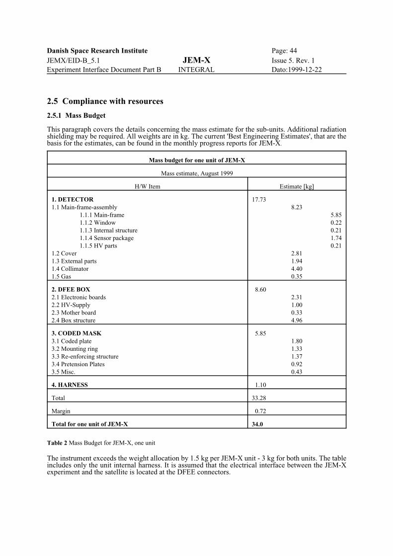
Danish Space Research Institute Page: 44JEMX/EID-B_5.1 JEM-X Issue 5. Rev. 1Experiment Interface Document Part B INTEGRAL Dato:1999-12-22
Mass budget for one unit of JEM-X
Mass estimate, August 1999
H/W Item Estimate [kg]
1. DETECTOR1.1 Main-frame-assembly
1.1.1 Main-frame1.1.2 Window1.1.3 Internal structure1.1.4 Sensor package1.1.5 HV parts
1.2 Cover1.3 External parts1.4 Collimator1.5 Gas
17.738.23
5.850.220.211.740.21
2.811.944.400.35
2. DFEE BOX2.1 Electronic boards2.2 HV-Supply2.3 Mother board2.4 Box structure
8.602.311.000.334.96
3. CODED MASK3.1 Coded plate3.2 Mounting ring3.3 Re-enforcing structure3.4 Pretension Plates3.5 Misc.
5.851.801.331.370.920.43
4. HARNESS 1.10
Total 33.28
Margin 0.72
Total for one unit of JEM-X 34.0
Table 2 Mass Budget for JEM-X, one unit
2.5 Compliance with resources
2.5.1 Mass Budget
This paragraph covers the details concerning the mass estimate for the sub-units. Additional radiationshielding may be required. All weights are in kg. The current 'Best Engineering Estimates', that are thebasis for the estimates, can be found in the monthly progress reports for JEM-X.
The instrument exceeds the weight allocation by 1.5 kg per JEM-X unit - 3 kg for both units. The tableincludes only the unit internal harness. It is assumed that the electrical interface between the JEM-Xexperiment and the satellite is located at the DFEE connectors.

Danish Space Research Institute Page: 45JEMX/EID-B_5.1 JEM-X Issue 5. Rev. 1Experiment Interface Document Part B INTEGRAL Dato:1999-12-22
JEM-X Experiment, both units
Modes: Off Standby Operation
Nominal TM data rate 0 0 2.25 packets/s
Table 3 The JEM-X TM rates
2.5.2 Power Budget
See § 3.4.7 Power Budget.
2.5.3 Data rate TM, TC
JEM-X will use all allowed TM data rate. The maximum actual TC rate is 1 packet/sec.

Danish Space Research Institute Page: 46JEMX/EID-B_5.1 JEM-X Issue 5. Rev. 1Experiment Interface Document Part B INTEGRAL Dato:1999-12-22
3 INTERFACE DEFINITIONThis chapter relates to the Mechanical Interface Control Drawings (ICDs) for the separate units in theexperiment. The name of the pdf-files of these drawings are:
JEMX-MASK: Mechanical ICD for the Coded Mask Interface. (PDF file: j-mask-i.pdf on DSRI jemx FTP)
JEMX-DETECTOR: Mechanical ICD for the Detector/DFEE assembly. (PDF file: j-det-b.pdf on DSRI jemx FTP)
(See 3.2.7 for Drawing Change Record Sheets).
The drawings can be found in A4 size in Appendix A.
For each of the major sub-units a specific unit number has been defined. The numbers are:
Unit numbers
Number Name Number location
130000 JEM-X Experiment N/A
130100 Detector/DFEE assembly - on the DFEE connectors plate
131000 Detector unit - on the main-frame
131100 Collimator unit - on the edge of the wall on the support ring
131200 Detector legs TBD
131300 Mirror cubes - on mirror cube bracket
132000 DFEE unit - on the DFEE connectors plate
133000 Coded mask unit TBD
The numbers are implemented as defined in the section 4.2.13 ‘Equipment identification’ in EID-A.
3.1 Definition of coordinate system for instrument.
The unit coordinate systems is defined on the ICDs.
3.2 Mechanical interfaces
3.2.1 Definition of structural dimensioning load cases
Structural dimensioning load cases have been defined for the Coded Mask and for the Detectorinterior/exterior according to the stiffness and strength requirements stated under section 4.2.2 and 4.2.3in EID-A, and the structural test requirements in section 5.4.4. These load cases have been the designdrivers for the current design.
3.2.2 Mechanical description of the instrument
Each JEM-X experiment consists of two units. The Detector/DFEE unit and the Coded Mask unit.
The Detector/DFEE unit defined as the assembly of the detector vessel with legs, the collimator, theDFEE box containing electronics and HV supplies and the unit interconnecting harness, and opticalreference cubes.

Danish Space Research Institute Page: 47JEMX/EID-B_5.1 JEM-X Issue 5. Rev. 1Experiment Interface Document Part B INTEGRAL Dato:1999-12-22
Figure 12 The Detector Cover
Figure 13 The Collimator layout
The Coded Mask unit is defined as the tungsten plate containing the hexagonal mask coding, asurrounding titanium mounting ring with elastic pretension devices, and the optical reference cubes.
The section below is a mechanical description each part.
3.2.2.1 Detector
The detector, which is shown in Figure 3, consists of the following modules: detector vessel, collimator,X-ray window and MS-sensor package. The gas inside the detector is at 5 bar pressure.
3.2.2.1.1 Detector Vessel
The detector body is made of stainless steel and consists of two parts, the main-frame and the coverwhich are joint together by electron beam welding. There are no gaskets.
The main-frame has a conical shape with a circular flange in the middle for mounting the collimator. Thegas filling tubes and vacuum tight signal connectorsand high voltage feed-throughs are welded to thismain-frame. The inside structure consists of twosets of vertical studs fastened to the main-frame.The field forming rings are mounted on one set ofstuds. The “spider”, a support structure for thedetector electronics and the microstrip plate (seedescription in section 1.3.2.1.4) is mounted onanother set of vertical studs.
The cover is formed from 2 mm thick stainless steelplate. The shape of the cover is similar to a pres-sure vessel cap form minimizing the weight andmaximizing the strength. The detector cover isshown in Figure 12.
3.2.2.1.2 Detector window
The detector window is a 0.25 mm thick berylliumfoil. The window is supported by the collimatorstructure against the internal operating pressure of 5bar. The window is glued to a stainless steel mount-ing ring which is welded to the detector main-frame.
3.2.2.1.3 Collimator
The collimator consists of an array of brazed lamellaeforming an array of square tubes of molybdenumwith a wall thickness of 0.45 mm, a center-to-centerspacing of 7.05 mm and a cell height of 57.0 mm.The lamellae are covered on both sides with layers ofcopper and aluminum. The collimator weight is about4.4 kg including the outer support ring which is alsomade of molybdenum. The collimator is mountedfrom top and down into the detector main-frameDuring transportation and storage the collimator willbe covered with a protection cover.
The collimator is shown in Figure 13.
3.2.2.1.4 Calibration sources
There are four radioactive calibration sources in eachJEM-X experiment. The sources ares mounted intofour cells of the collimator and each illuminate a well

Danish Space Research Institute Page: 48JEMX/EID-B_5.1 JEM-X Issue 5. Rev. 1Experiment Interface Document Part B INTEGRAL Dato:1999-12-22
Figure 14 Mounting the JEM-X Detector/DFEE unit in theintegration plane.
defined spot on the microstrip plate. The sources are placed so that each illuminate one of the four anodesections in the detector. The sources are shielded so all radiation is kept within the detector volume. Thesource locations are indicated in figure 13.
3.2.2.2 DFEE box
The Detector Front End Electronics is located in a box just below the detector vessel. The box and itssupport brackets are machined from a single piece of aluminium. All electronics boards are mechanicallyclamped along three edges for optimizing the mechanical support and facilitating the heat conductance.The Detector Front End Electronics occupies eight circuit boards, a mother-board and a HV supply. Four brackets on the DFEE box form the interface between the Detector/DFEE assembly and the PLM.The brackets transfer the loads during launch and they also provide heat conductance to the PLM.
The box is shown on the MICD in Appendix A.
3.2.2.3 Coded Mask
The coded mask is realized as a pre-stressed membrane mounted in a peripheral ring and supported byan exo-skeleton in order to have the required strength and stiffness during launch. The supportingskeleton will be made of titanium. The active diameter of the coded mask is 535 mm and the ring aroundit is 15 mm wide and approximately 70 mm high. Excluding the alignment cubes the envelope for onemask is: Ø565 with a height of: 110 mm.
The code pattern is cut in a 0.5 mm thick tungsten plate. The hexagonal holes have a centre-to-centreseparation of 3.3 mm. The interface drawing can be found in the MICD in Appendix A.
3.2.3 Mounting concept
JEM-X will arrive for integration as two identical sets each consisting of a Coded Mask unit and aDetector/DFEE unit.
The Detector/DFEE unit will be mountedbottom up in its transportation box. Whenreleased from the box the unit can be liftedout, and mounted into the integration plane asshown in Figure 14. Checking, cleaning andhandling procedure before mounting will bedefined by DSRI and Metorex.
The position of the center of each detector isindicated by a white reference cross located onthe central ribs on top of the collimator.
3.2.4 Mechanisms design
There are no mechanisms on JEM-X.
3.2.5 Alignment requirements/stability
See section 2.1.3 for alignment requirements.

Danish Space Research Institute Page: 49JEMX/EID-B_5.1 JEM-X Issue 5. Rev. 1Experiment Interface Document Part B INTEGRAL Dato:1999-12-22
DRAWING CHANGE RECORD SHEET
DRAWING NUMBER: JEMX-MASK-n, where n is Issue No. ORIGINATOR
Uni. de Val./DSRITITLE: Coded Mask Interface
ISSUE DESCRIPTION OF CHANGE AUTH. DATE
A Banner added for the appendix version. DSRI 12.9.95
DStrong-back system added.Envelope changed to Ø565, height: 110 mm, one unit.Corresponding JEM-X EID-B drawing number added.
Uni. deVal
DSRI
17.02.96
18.02.96
E No change
F
Single-sided strong-back changed to double-sided hexo-skeleton.A second ring has been introduced in the reinforcement structure in orderto be able to support the acoustic and the sine spectrum environmentduring launch.Hexo-skeleton rotated approx. 4 deg. around X axis.Coded Membrane Plate height changed from 58.0 to 60.0 mm
Uni. deVal.
12.01.97
G Interface bolts changed to: M5.0, see location K11 - L11 on drawingUni. de
Val14.04.97
H No changeUni. de
Val05.11.97
I
In order to add more strength to the central area of the CM membrane theopen area is reduced from 50% to 25% by closing some of the open pixelslocated in the central area and under the re-enforcement structure.A third ring is introduced in the re-enforcement structure.Optical cubes for alignment are added to the Masks.RTV 566 silicone used for re-enforcement structure bonding to codedmembrane.
Uni. deVal.
-SENER
08.06.98
Table 4 DCRS for JEMX-MASK-n.
3.2.6 Structural Math Model
A simplified SMM for the Detector/DFEE assembly can be found in document: ‘Simplified SMM for theJEM-X-STM Detector/DFEE assembly’ (IN-RP-JM-0001, v 1.0, 980609). This document describes areduced nodal model in ANSYS of the STM Detector/DFEE assembly, and in greater therms it is validfor FM/QM also. The model can be converted and merged into the general S/C SMM.
For the Coded mask see documents from Univ. de Valencia: IN-JX-SR-RPT-002 (24/09/97) and IN-JX-SR-NOT-002 (02/06/97).
3.2.7 Mechanical ICD for the units.
The ICD for the JEM-X unit is shown in Appendix A. The Drawing Change Record Sheets for thedrawings are given below.
Danish Space Research Institute Page: 50JEMX/EID-B_5.1 JEM-X Issue 5. Rev. 1Experiment Interface Document Part B INTEGRAL Dato:1999-12-22
DRAWING CHANGE RECORD SHEET FOR JEM-X QM AND FM DETECTOR BLOCK
DRAWING NUMBER:130100-n, where n is Issue No. ORIGINATOR
DSRI
ISSUE DESCRIPTION OF CHANGE AUTH. DATE
A New MICD corresponding to new detector and DFEE box design DSRI 24.09.99
Table 5 DCRS for JEM-X ICD 130100-n.
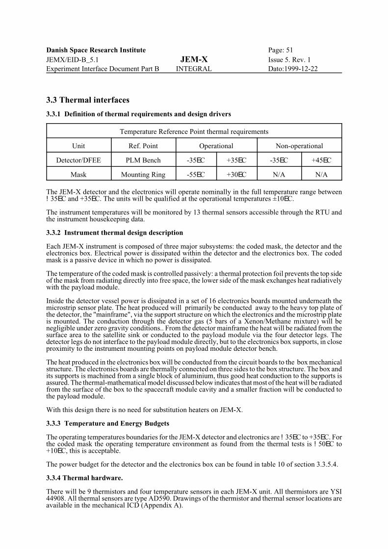
Danish Space Research Institute Page: 51JEMX/EID-B_5.1 JEM-X Issue 5. Rev. 1Experiment Interface Document Part B INTEGRAL Dato:1999-12-22
3.3 Thermal interfaces
3.3.1 Definition of thermal requirements and design drivers
Temperature Reference Point thermal requirements
Unit Ref. Point Operational Non-operational
Detector/DFEE PLM Bench -35EC +35EC -35EC +45EC
Mask Mounting Ring -55EC +30EC N/A N/A
The JEM-X detector and the electronics will operate nominally in the full temperature range between!35EC and +35EC. The units will be qualified at the operational temperatures ±10EC.
The instrument temperatures will be monitored by 13 thermal sensors accessible through the RTU andthe instrument housekeeping data.
3.3.2 Instrument thermal design description
Each JEM-X instrument is composed of three major subsystems: the coded mask, the detector and theelectronics box. Electrical power is dissipated within the detector and the electronics box. The codedmask is a passive device in which no power is dissipated.
The temperature of the coded mask is controlled passively: a thermal protection foil prevents the top sideof the mask from radiating directly into free space, the lower side of the mask exchanges heat radiativelywith the payload module.
Inside the detector vessel power is dissipated in a set of 16 electronics boards mounted underneath themicrostrip sensor plate. The heat produced will primarily be conducted away to the heavy top plate ofthe detector, the "mainframe", via the support structure on which the electronics and the microstrip plateis mounted. The conduction through the detector gas (5 bars of a Xenon/Methane mixture) will benegligible under zero gravity conditions.. From the detector mainframe the heat will be radiated from thesurface area to the satellite sink or conducted to the payload module via the four detector legs. Thedetector legs do not interface to the payload module directly, but to the electronics box supports, in closeproximity to the instrument mounting points on payload module detector bench.
The heat produced in the electronics box will be conducted from the circuit boards to the box mechanicalstructure. The electronics boards are thermally connected on three sides to the box structure. The box andits supports is machined from a single block of aluminium, thus good heat conduction to the supports isassured. The thermal-mathematical model discussed below indicates that most of the heat will be radiatedfrom the surface of the box to the spacecraft module cavity and a smaller fraction will be conducted tothe payload module.
With this design there is no need for substitution heaters on JEM-X.
3.3.3 Temperature and Energy Budgets
The operating temperatures boundaries for the JEM-X detector and electronics are !35EC to +35EC. Forthe coded mask the operating temperature environment as found from the thermal tests is !50EC to+10EC, this is acceptable.
The power budget for the detector and the electronics box can be found in table 10 of section 3.3.5.4.
3.3.4 Thermal hardware.
There will be 9 thermistors and four temperature sensors in each JEM-X unit. All thermistors are YSI44908. All thermal sensors are type AD590. Drawings of the thermistor and thermal sensor locations areavailable in the mechanical ICD (Appendix A).
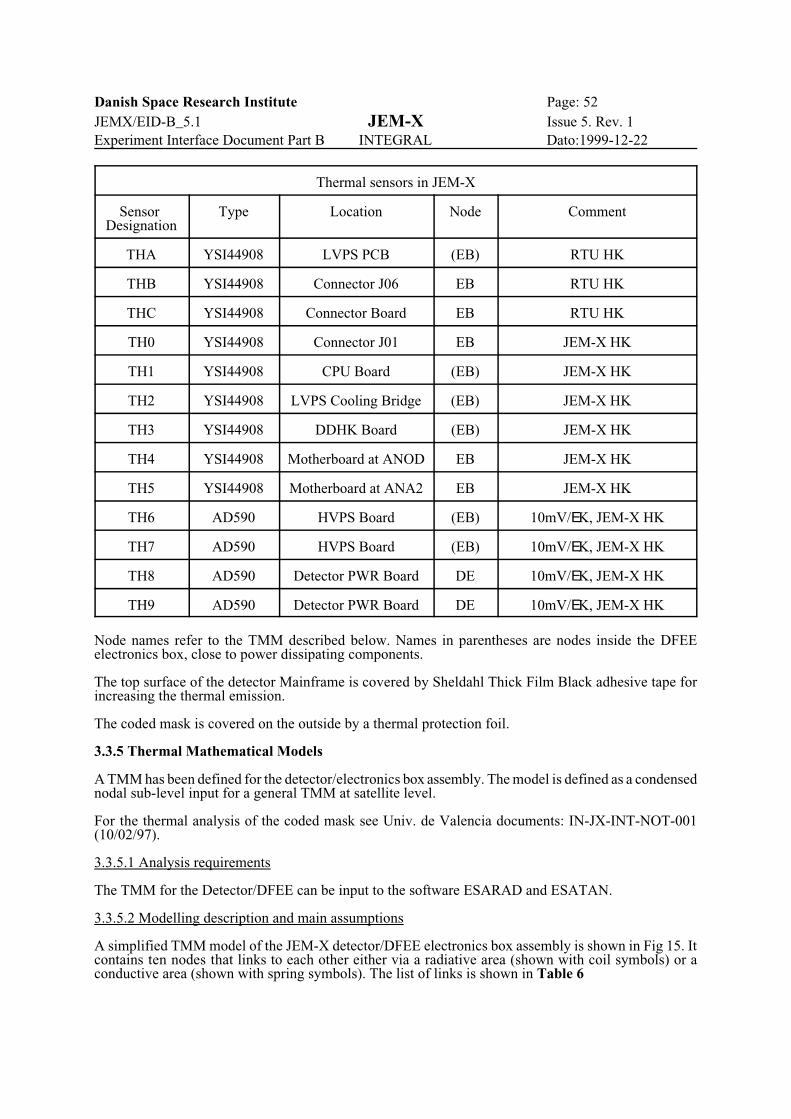
Danish Space Research Institute Page: 52JEMX/EID-B_5.1 JEM-X Issue 5. Rev. 1Experiment Interface Document Part B INTEGRAL Dato:1999-12-22
Thermal sensors in JEM-X
Sensor Designation
Type Location Node Comment
THA YSI44908 LVPS PCB (EB) RTU HK
THB YSI44908 Connector J06 EB RTU HK
THC YSI44908 Connector Board EB RTU HK
TH0 YSI44908 Connector J01 EB JEM-X HK
TH1 YSI44908 CPU Board (EB) JEM-X HK
TH2 YSI44908 LVPS Cooling Bridge (EB) JEM-X HK
TH3 YSI44908 DDHK Board (EB) JEM-X HK
TH4 YSI44908 Motherboard at ANOD EB JEM-X HK
TH5 YSI44908 Motherboard at ANA2 EB JEM-X HK
TH6 AD590 HVPS Board (EB) 10mV/EK, JEM-X HK
TH7 AD590 HVPS Board (EB) 10mV/EK, JEM-X HK
TH8 AD590 Detector PWR Board DE 10mV/EK, JEM-X HK
TH9 AD590 Detector PWR Board DE 10mV/EK, JEM-X HK
Node names refer to the TMM described below. Names in parentheses are nodes inside the DFEEelectronics box, close to power dissipating components.
The top surface of the detector Mainframe is covered by Sheldahl Thick Film Black adhesive tape forincreasing the thermal emission.
The coded mask is covered on the outside by a thermal protection foil.
3.3.5 Thermal Mathematical Models
A TMM has been defined for the detector/electronics box assembly. The model is defined as a condensednodal sub-level input for a general TMM at satellite level.
For the thermal analysis of the coded mask see Univ. de Valencia documents: IN-JX-INT-NOT-001(10/02/97).
3.3.5.1 Analysis requirements
The TMM for the Detector/DFEE can be input to the software ESARAD and ESATAN.
3.3.5.2 Modelling description and main assumptions
A simplified TMM model of the JEM-X detector/DFEE electronics box assembly is shown in Fig 15. Itcontains ten nodes that links to each other either via a radiative area (shown with coil symbols) or aconductive area (shown with spring symbols). The list of links is shown in Table 6

Danish Space Research Institute Page: 53JEMX/EID-B_5.1 JEM-X Issue 5. Rev. 1Experiment Interface Document Part B INTEGRAL Dato:1999-12-22
Node Acronym
Description Radiative coupling with nodes
Conductive coupling with nodes
DE Detector Electronics VS
VS Detector Vessel S1 P1 to P4
P1 Support Structure 1 VS, EB, PM
P2 Support Structure 2 VS, EB, PM
P3 Support Structure 3 VS, EB, PM
P4 Support Structure 4 VS, EB, PM
PM PLM Detector Bench P1 to P4
EB DFEE Electronics Box S2 P1 to P4
S1 Payload Module Radiative Sink VS
S2 Spacecraft Module Radiative Sink EB
Table 6 JEM-X detector/electronics box node definition summary
The model makes use of the symmetry of JEM-X, only one node is defined at each level, except for the four support structures, which are modelled separately to maintain compatibility with the earlierJEM-X thermal models.
A heat capacity is assigned to each JEM-X node according to the specific material and mass. The sub-division is described below.
DE: The Detector Electronics node includes both the detector internal electronics and support structures,the field forming rings, the microstrip plate and the gas. Power is dissipated by the electronics andconducted via the internal supports to the vessel, VS. Conduction through the gas is insignificant underzero gravity conditions. The effect of the radiative transfer from the electronics to the vessel is includedin the heat conduction term, the value of this term is determined from a test with the vessel evacuated,i.e. the effect of convective heat transfer was eliminated.
VS: The Detector Vessel consists of a massive steel ring, the mainframe, on which the collimator, thebottom cover and the detector legs are mounted. The radiative area of the structure towards the PayloadModule Radiative Sink (node S1) is taken to be the top surface of the mainframe plus the collimator. Thedetector legs do not have their own node, the heat capacity of the legs have been allocated partly (50%)to the detector vessel node, and partly to the support structure nodes, P1 to P4.
P1 to P4: The Support Structures are the four extensions of the electronics box which interfaces to thePLM detector bench and to the detector legs. The peripheral parts of the support structures connects tothe satellite sink nodes, PM, and to the detector mainframe, VS, via the legs. The material is aluminium.
EB: The DFEE Electronics Box is an aluminium box housing the main electronics (the DFEE). Mostof the electrical power is dissipated in this node. Heat is conducted to the support structure, P1 to P4. Thelower face and part of the sides of the electronics box radiates to the spacecraft module sink, S2. The sidefaces of the electronics box and the unit supports are machined from a single block of aluminium, thusthe heat conductivity is optimized. The box is painted with Chemglaze Z306.
PM: The PLM Detector Bench is the conductive sink for JEM-X
S1: The Payload Module Radiative Sink is the sink for the topside of the detector vessel.
S2: The Spacecraft Module Radiative Sink is the sink for the lower face of the electronics box.
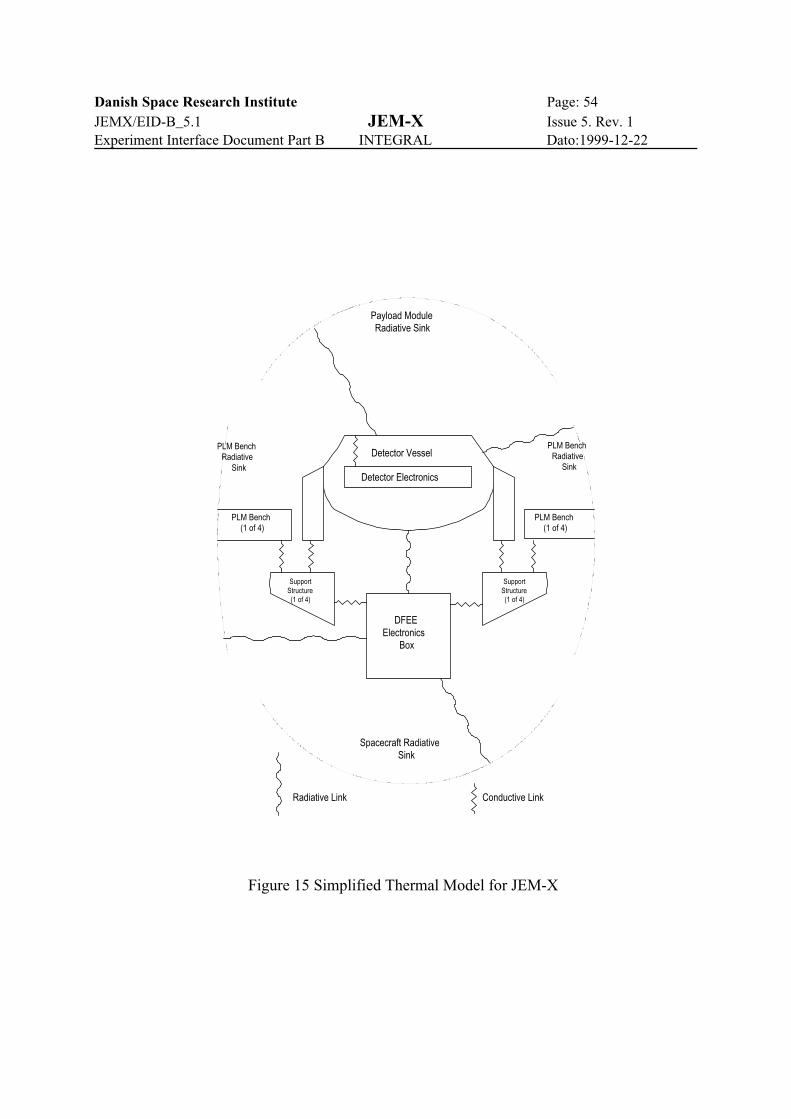
Danish Space Research Institute Page: 54JEMX/EID-B_5.1 JEM-X Issue 5. Rev. 1Experiment Interface Document Part B INTEGRAL Dato:1999-12-22
PLM Bench(1 of 4)
PLM Bench(1 of 4)
SupportStructure(1 of 4)
SupportStructure(1 of 4)
DFEEElectronics
Box
Detector Electronics
Detector Vessel
Payload ModuleRadiative Sink
Spacecraft RadiativeSink
PLM BenchRadiative
Sink
PLM BenchRadiative
Sink
Radiative Link Conductive Link
Figure 15 Simplified Thermal Model for JEM-X

Danish Space Research Institute Page: 55JEMX/EID-B_5.1 JEM-X Issue 5. Rev. 1Experiment Interface Document Part B INTEGRAL Dato:1999-12-22
PLM Module
Spacecraft Module
PLMBench
DFEE
Detector
The radiation environment of JEM-X is illustrated in the diagram shown here. The top surface of thedetector facing the payload module has a high emissivity (g-0.85) whereas the sides and bottom facingthe payload bench and the DFEE box is electropolished steel with (g-0.35). The DFEE box is paintedwith Chemglaze Z306 on all six faces.
3.3.5.3 Model file
The model is described in the tables below.
From node To node K[W/EK]
DE VS 0.25
VS P1 to P4 0.16 (each of 4)
P1 to P4 PM 0.5 (each of 4)(including contact resistance)
EB P1 to P4 1.15 (each of 4)
Table 7. Detector and DFEE conductive coupling data
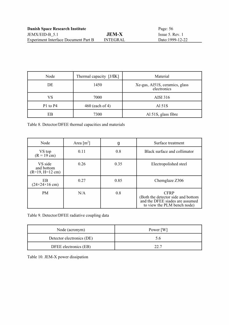
Danish Space Research Institute Page: 56JEMX/EID-B_5.1 JEM-X Issue 5. Rev. 1Experiment Interface Document Part B INTEGRAL Dato:1999-12-22
Node Thermal capacity [J/EK] Material
DE 1450 Xe-gas, Al51S, ceramics, glasselectronics
VS 7000 AISI 316
P1 to P4 460 (each of 4) Al 51S
EB 7300 Al 51S, glass fibre
Table 8. Detector/DFEE thermal capacities and materials
Node Area [m2] g Surface treatment
VS top(R = 19 cm)
0.11 0.8 Black surface and collimator
VS side and bottom
(R=19, H=12 cm)
0.26 0.35 Electropolished steel
EB(24×24×16 cm)
0.27 0.85 Chemglaze Z306
PM N/A 0.8 CFRP(Both the detector side and bottomand the DFEE siades are assumed
to view the PLM bench node)
Table 9. Detector/DFEE radiative coupling data
Node (acronym) Power [W]
Detector electronics (DE) 5.6
DFEE electronics (EB) 22.7
Table 10. JEM-X power dissipation

Danish Space Research Institute Page: 57JEMX/EID-B_5.1 JEM-X Issue 5. Rev. 1Experiment Interface Document Part B INTEGRAL Dato:1999-12-22
Figure 17 Power interface
3.4 Electrical power supply
3.4.1 Instrument power supply
The DC/DC power converter(s) will give galvanic insulation between primary power lines, secondarypower lines and equipment structure (bonding stud) in accordance with EID-A 4.4.3.1 and 4.6.2.1.
Any voltage on the main bus power line in the full range 0 V to 30 V, including short circuit of the powerline, is harmless to the instrument.
The interfaces will be designed such that no instrument failure can propagate into spacecraft subsystem.Protection against failures in the harness connection between the PDU and the JEM-X power input isensured by the current limitation circuitry in the PDU.
3.4.2 Power supply block diagram
Figure 17 shows the power supply block diagram.
3.4.3 Required power lines
3.4.3.1 Power bus lines for DFEE & DAE (PDU)
+28 V. Redundant LCL connection.GND. Redundant connection.

Danish Space Research Institute Page: 58JEMX/EID-B_5.1 JEM-X Issue 5. Rev. 1Experiment Interface Document Part B INTEGRAL Dato:1999-12-22
3.4.4 Pyrotechnic interfaces
There are no pyrotechnic devices in JEM-X.
3.4.5 Power profile
There are 3 power modes:• Power Mode 1: DFEE OFF, HVC OFF• Power Mode 2: DFEE ON, HVC OFF• Power Mode 3: DFEE ON, HVC ON
Switching between Power Mode 1, Power Mode 2 and Power Mode 3 will give inrush current below thevalues given in EID-A, section 4.4.2.2.
After inrush, there will be only small fluctuations in power consumption in each of the functional,scientific modes.
3.4.5.1 Power requirement for each of two identical instruments
See table 11, Power budget.
3.4.6 Electrical ICD
The electrical ICD according to DRD44-1 is attached as Appendix B
3.4.6.1 Power connector J07 and J08
Power interface to the PDU is via 2 Cannon connectors Royal-D-9P:
- Signal names and pin connections in Appendix B.
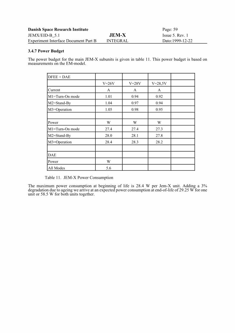
Danish Space Research Institute Page: 59JEMX/EID-B_5.1 JEM-X Issue 5. Rev. 1Experiment Interface Document Part B INTEGRAL Dato:1999-12-22
3.4.7 Power Budget
The power budget for the main JEM-X subunits is given in table 11. This power budget is based onmeasurements on the EM-model.
DFEE + DAE
V=26V V=28V V=28,5V
Current A A A
M1=Turn-On mode 1.01 0.94 0.92
M2=Stand-By 1.04 0.97 0.94
M3=Operation 1.05 0.98 0.95
Power W W W
M1=Turn-On mode 27.4 27.4 27.3
M2=Stand-By 28.0 28.1 27.8
M3=Operation 28.4 28.3 28.2
DAE
Power W
All Modes 5.6
Table 11. JEM-X Power Consumption
The maximum power consumption at beginning of life is 28.4 W per Jem-X unit. Adding a 3%degradation due to ageing we arrive at an expected power consumption at end-of-life of 29.25 W for oneunit or 58.5 W for both units together.

Danish Space Research Institute Page: 60JEMX/EID-B_5.1 JEM-X Issue 5. Rev. 1Experiment Interface Document Part B INTEGRAL Dato:1999-12-22
3.5 EMC-Design
3.5.1 Instrument Design Concept
The experiment consists of two units:
1: A detector in a pressurized enclosure together with front end electronics DAE. This enclosure isdescribed 1.3.2.1. The entire enclosure, including the beryllium detector is electrically conducting.
2: The main electronics circuitry is contained in a box, which is milled from a solid aluminium block withan aluminium cover at the top and bottom. The high voltage supplies and the DC/DC converters aresituated in this box.
Electrical connections between JEM-X and the satellite will be implemented in accordance withparagraph 4.5.2.3 (Electrical Interfaces) of the INTEGRAL EID-A.
Only one connection exists between instrument signal GND and structure GND. The most noise sensitiveelements in the JEM-X instrument are the preamplifiers connected to the electrodes on the microstripplate. The location of the connection between signal GND and structure GND are located inside thedetector vessel in order to prevent capacitive pick up of noise signals from the vessel to the circuitsinside.
3.5.2 Instrument Block Diagram
Figure 18 shows the instrument grounding scheme. An important feature in the grounding scheme is, thatcircuit GND is connected to structure in the DAE. This is necessary, because any noise voltage betweenthe detector window and the micro-strip plate will be seen as a signal by the pre-amplifiers.
3.5.3 Susceptibility to EMC-Interference
JEM-X does not include items, that are susceptible to EMC-interference to a higher degree than what isnormally expected for electronic circuits.
3.5.4 Possible High EMC-Emission
JEM-X will use switch-mode low voltage and high voltage power supplies.
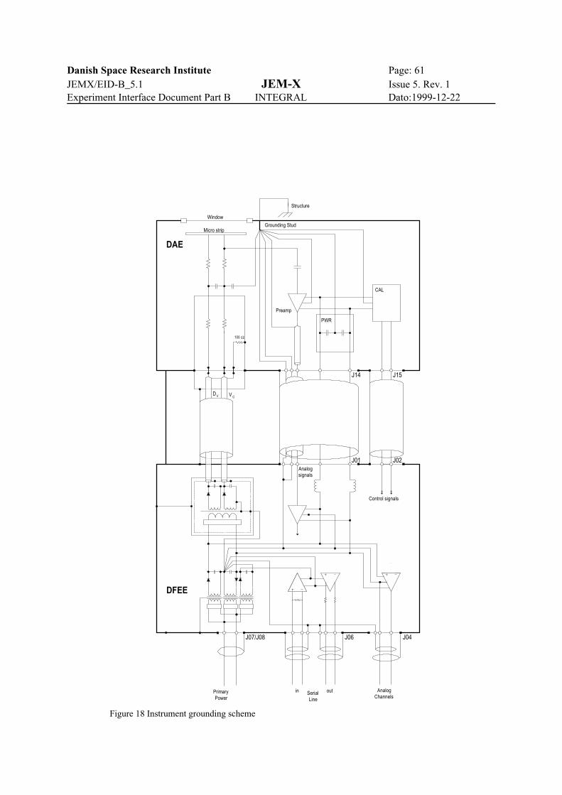
Danish Space Research Institute Page: 61JEMX/EID-B_5.1 JEM-X Issue 5. Rev. 1Experiment Interface Document Part B INTEGRAL Dato:1999-12-22
100 Ω
Window
Micro strip
CAL
Preamp
PWR
Analogsignals
Control signals
PrimaryPower
in outSerialLine
AnalogChannels
DAE
DFEE
Grounding Stud
J04J06J07/J08
J01 J02
J15J14
V CD V
Structure
Figure 18 Instrument grounding scheme
Danish Space Research Institute Page: 62JEMX/EID-B_5.1 JEM-X Issue 5. Rev. 1Experiment Interface Document Part B INTEGRAL Dato:1999-12-22
3.6 Data handling interfaces.
3.6.1 Instrument data handling design definition.
The JEM-X on-board software will be distributed between the DFEE and the DPE processors.
The DFEE processor will interface to the detector read out electronics on one side and to the DPE on theother. The software in the DFEE processor will perform the following tasks:
S Software initialization and code corrections according to instructions from the DPE(on power-up)
S Detector read-out controlS Single event evaluationS Identification of X-ray events from the radioactive sourcesS Background rejectionS Event statistics collectionS Event buffering and transmission to DPES DFEE HK collection and transmission to DPES Hardware parameter control.S Transmission of Memory Dump data according to requests received from the DPE
The DPE will interface to the DFEE on the one side and to the OBDH on the other. The IASW softwaresupplied by the PI-team will perform the following tasks:
S Data reception from the front-end processor (Science data via High Speed link, allother data via Low Speed link)
S Data compression and build-up of science TM-packet data fields, last 430 bytes, (verylast two bytes used for CSSW generated CRC)
S Generation of On-Request TM-packet data fields according to TC requests, last 430bytes, (very last two bytes used for CSSW generated CRC)
S Housekeeping data acquisition and build-up of HK-packet data fields, about 262bytes, leaving room for DPE internal HK data and On-Event Reports (80 bytes)
S Telemetry transfer to CSSWS Telecommand reception, decoding and execution/rejectionS Safe storage of instrument parameters (H/W and S/W) as well as code correction
sequences
The development of the on-board software will comply with ESA PSS-05-0. The DPE software will bewritten in ADA, but for reasons of processing speed the DFEE software will be written in assembler.
The software will be placed in ROM and downloaded to RAM before execution. Code, fixed constantsand variable parameters will be placed in distinct areas in memory. It will be possible to uplinkcorrections to the code from the ground prior to execution. For the DFEE software the code correctionsare stored in the DPE and transferred to the DFEE as part of the DFEE software initialization process onpower-up.
3.6.2 Internal timing concept.
The DFEE will have an internal clock driven by a 8192 Hz signal derived from the 4.194304 MHz signalprovided through the DPE. Thus the timing accuracy for the JEM-X is 122.07 microseconds. The DFEEclock will be reset every 8 seconds. The clock reset signal is derived from the BCP2 signal (1 Hz), whichis stable with respect to the 4 MHz master signal. The BCP1 signal is used as a gate for the BCP2,limiting the reset frequency to 1/8 Hz.
The events transmitted from the DFEE to the DPE will be time stamped using two 16 bit words, onecontaining the reading of the DFEE clock (advancing every 122.07 microseconds) and another wordcounting the number of clock resets.
The DPE will read the “freeze register 1” in the Remote Bus Interface (RBI) every 8 s in synchronismwith the clock reset operation in the DFEE. The DPE is therefore able to correlate the event time stamps

Danish Space Research Institute Page: 63JEMX/EID-B_5.1 JEM-X Issue 5. Rev. 1Experiment Interface Document Part B INTEGRAL Dato:1999-12-22
from the DFEE to the OBT readings from the RBI.
Due to the existence of the “higher order time words” in the event timing, there will not be any 8 sambiguity in the correlation between DFEE time and OBT.
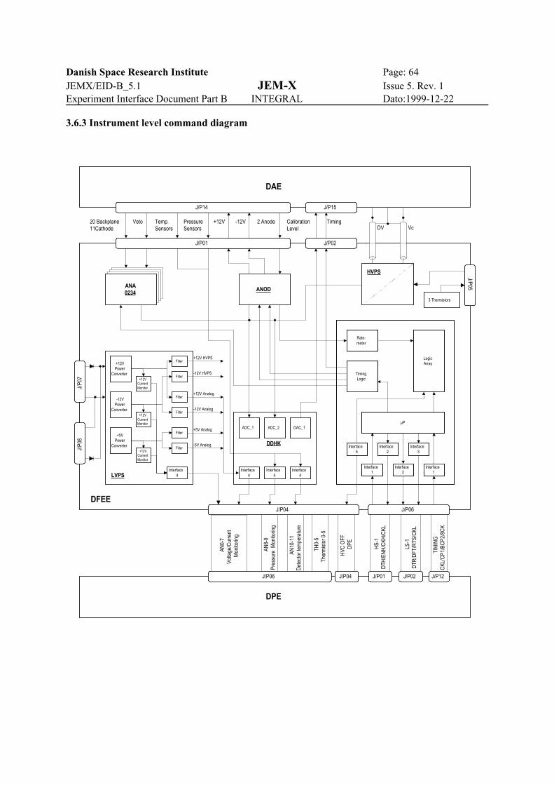
Danish Space Research Institute Page: 64JEMX/EID-B_5.1 JEM-X Issue 5. Rev. 1Experiment Interface Document Part B INTEGRAL Dato:1999-12-22
TIM
ING
CKL
/CP1
/BC
P2/8
CK
LS-1
DTR
/DFT
/RTS
/CKL
TH0-
5Th
erm
isto
r 0-5
AN10
-11
Det
ecto
r tem
pera
ture
HVC
OFF
DPE
AN8-
9Pr
essu
re M
onito
ring
AN0-
7Vo
ltage
/Cur
rent
Mon
itorin
gJ/P02
J/P05
ANOD
Rate-meter
LogicArray
µP
Interface5
Interface3
Interface2
Interface1
Interface1
Interface2
TimingLogic
ANA0234
J/P01
20 Backplane11Cathode
Veto Temp.Sensors
PressureSensors
+12V -12V 2 Anode TimingCalibrationLevel
J/P0
7J/
P08
+12V HVPS
-12V HVPS
-5V Analog
-12V Analog
+12V Analog
+12VPower
Converter+12V
CurrentMonitor
Filter
+12VCurrentMonitor
+12VCurrentMonitor
Interface4
Filter
Filter
Filter
Filter
Filter
-12VPower
Converter
+5VPower
Converter
LVPS
+5V Analog
Interface4
ADC_1 ADC_2
Interface4
Interface4
DDHK
DAC_1
Rate-meter
LogicArray
µP
Interface5
Interface3
Interface2
Interface1
Interface1
Interface2
TimingLogic
DV Vc
DAE
J/P15J/P14
DFEE
DPE
J/P06
HS-
1D
TH/E
NH
/CKH
/CKL
J/P04 J/P06
J/P04 J/P01 J/P02 J/P12
HVPS
3 Thermistors
3.6.3 Instrument level command diagram

Danish Space Research Institute Page: 65JEMX/EID-B_5.1 JEM-X Issue 5. Rev. 1Experiment Interface Document Part B INTEGRAL Dato:1999-12-22
3.6.4 Interfaces per instrument unit
3.6.4.1 DPE channels
1 discrete command line (DPE HVC OFF)1 low speed serial line (TC)1 high speed serial line (TM)16 analogue lines (HK data)10 thermistor lines (HK)4 timing lines (4.194304 MHz, 8Hz, 1Hz, 1/8Hz)
3.6.4.2 RTU channels.
3 thermistor channels1 discrete command line (S/C HVC OFF)
3.6.5 Definition of TC packet rate per instrument mode.
The nominal allocation of telemetry packets for JEM-X is 18 packets per polling cycle (8 seconds). Eachpacket has a total length 440 bytes of which 12 bytes are used for headers and CRC, leaving 428 bytesavailable for instrument data. Each JEM-X unit will use one (and only one) TM packet for HKinformation for every polling cycle. This leaves 16 packets for science. The 16 packets may be distributedevenly to the two instruments, this will typically be the case when observing source fields with low X-rayactivity, or the packets may be distributed unevenly in order to exploit better the telemetry allocation, incase different formats are selected for the two instruments.
When observing intense X-ray sources JEM-X will generate data at higher data rates than thetransmission allocation will allow. Then on-board data reduction must take place. This part of the on-board processing is designed to exploit effectively the available transmission capacity. Therefore JEM-Xwill fill the allocated TM capacity most of the time. Both the DFEE and the DPE software will be ableto handle data congestion gracefully, for instance in case the data read-out from the DFEE or from theDPE hangs up.
On-Request telemetry packets will be used only for diagnostic purposes, and will not affect the averagetelemetry budget in a significant way.
If data are available each JEM-X unit will be able to support all packet rates between 1 and 191 packetsper cycle as long as the DPE is on and the IASW is active. One packet per cycle is guaranteed to be a HKpacket.
In case the DFEE is inactive the DPE will still fill part of the HK Package with meaningfull data. If theDFEE is inactive because the Low voltage is off, then the only valid data will be the DPE internal dataand some thermistor data. If Low Voltage is On, but the DFEE CPU is Off, also the instrument HKmonitored by the DPE will be valid.
Thus, the packet rate will be zero from a JEM-X unit in the OFF mode and it will be defined by thepolling sequence in all other modes where the IASW is active. What response the CSSW will have topacket requests if the IASW is left in the inactive state (see the JEM-X state diagram in section 3.7.6.1)is beyond the control of the JEM-X software.
3.6.6 Data handling interface.
3.6.6.1 Housekeeping Connector J04
Housekeeping monitor channels are connected to the DPE via a Cannon connector Royal-D - 37S:
Signal names and Pin connections in Appendix B.

Danish Space Research Institute Page: 66JEMX/EID-B_5.1 JEM-X Issue 5. Rev. 1Experiment Interface Document Part B INTEGRAL Dato:1999-12-22
3.6.6.2 Serial communication connector J06
The serial communication channels are connected to the DPE via a Cannon connector Royal-D-37S:
Signal names and Pin connections in Appendix B.
3.6.6.3 Discrete commands connector J05
The discrete commands are connected to JEM-X via a Cannon connector Royal D-37:
Signal names and Pin connections in Appendix B.
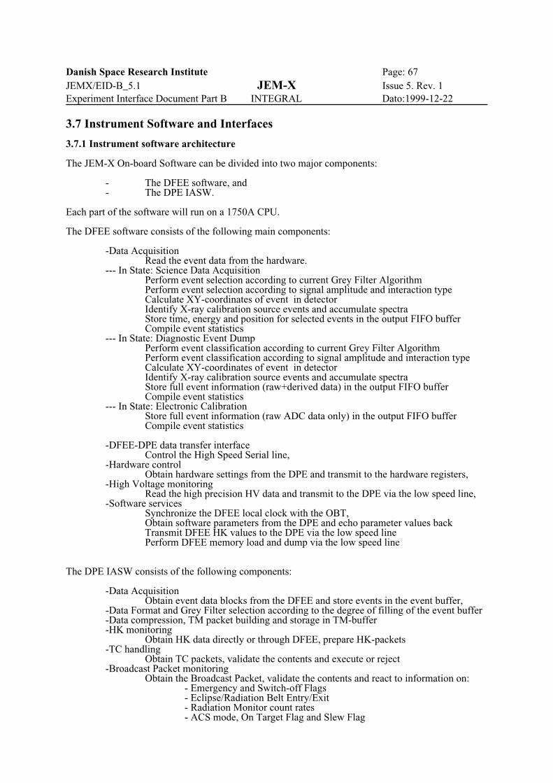
Danish Space Research Institute Page: 67JEMX/EID-B_5.1 JEM-X Issue 5. Rev. 1Experiment Interface Document Part B INTEGRAL Dato:1999-12-22
3.7 Instrument Software and Interfaces
3.7.1 Instrument software architecture
The JEM-X On-board Software can be divided into two major components:
- The DFEE software, and - The DPE IASW.
Each part of the software will run on a 1750A CPU.
The DFEE software consists of the following main components:
-Data AcquisitionRead the event data from the hardware.
--- In State: Science Data AcquisitionPerform event selection according to current Grey Filter AlgorithmPerform event selection according to signal amplitude and interaction type Calculate XY-coordinates of event in detectorIdentify X-ray calibration source events and accumulate spectraStore time, energy and position for selected events in the output FIFO bufferCompile event statistics
--- In State: Diagnostic Event DumpPerform event classification according to current Grey Filter AlgorithmPerform event classification according to signal amplitude and interaction type Calculate XY-coordinates of event in detectorIdentify X-ray calibration source events and accumulate spectraStore full event information (raw+derived data) in the output FIFO bufferCompile event statistics
--- In State: Electronic CalibrationStore full event information (raw ADC data only) in the output FIFO bufferCompile event statistics
-DFEE-DPE data transfer interfaceControl the High Speed Serial line,
-Hardware control Obtain hardware settings from the DPE and transmit to the hardware registers,-High Voltage monitoring Read the high precision HV data and transmit to the DPE via the low speed line, -Software services Synchronize the DFEE local clock with the OBT, Obtain software parameters from the DPE and echo parameter values back
Transmit DFEE HK values to the DPE via the low speed linePerform DFEE memory load and dump via the low speed line
The DPE IASW consists of the following components:
-Data AcquisitionObtain event data blocks from the DFEE and store events in the event buffer,
-Data Format and Grey Filter selection according to the degree of filling of the event buffer-Data compression, TM packet building and storage in TM-buffer-HK monitoring
Obtain HK data directly or through DFEE, prepare HK-packets-TC handling
Obtain TC packets, validate the contents and execute or reject-Broadcast Packet monitoring
Obtain the Broadcast Packet, validate the contents and react to information on:- Emergency and Switch-off Flags- Eclipse/Radiation Belt Entry/Exit- Radiation Monitor count rates- ACS mode, On Target Flag and Slew Flag
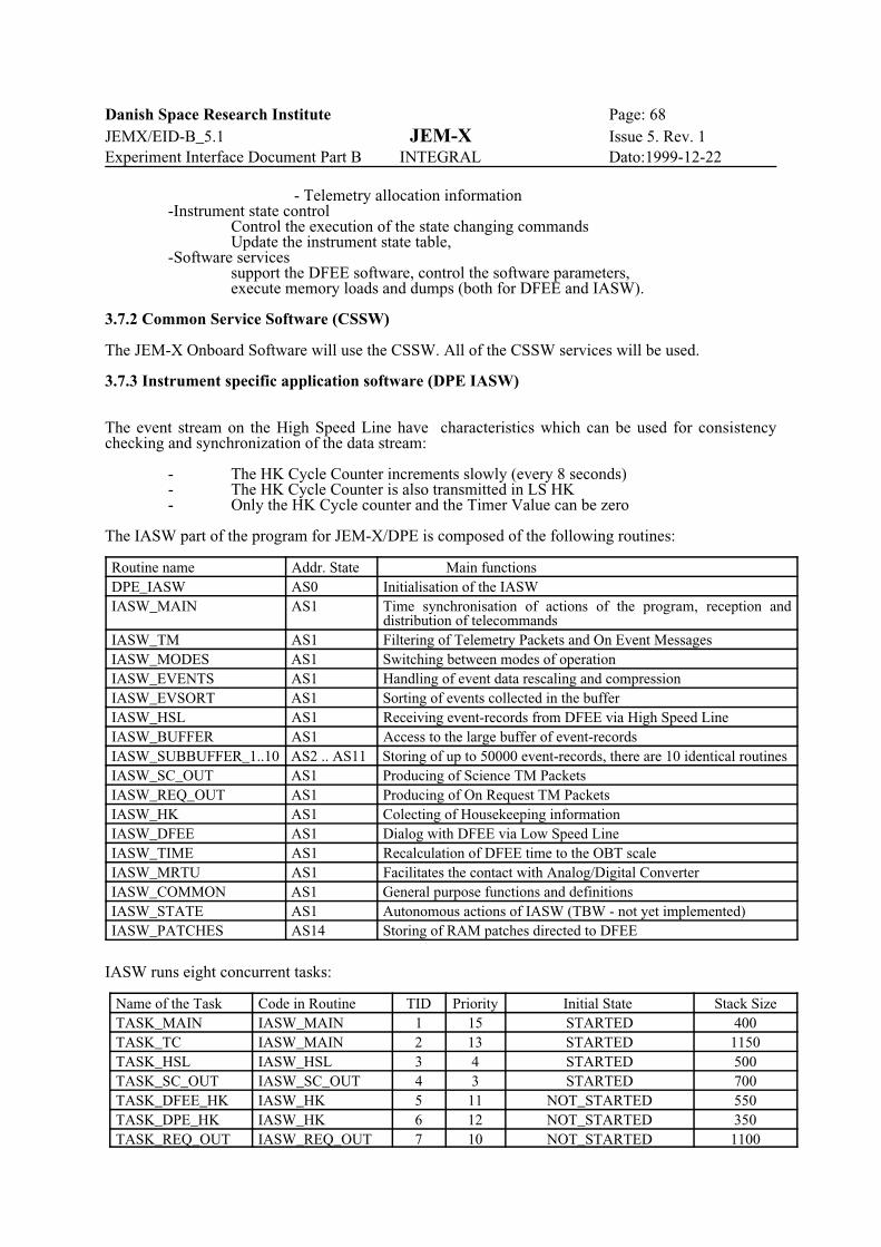
Danish Space Research Institute Page: 68JEMX/EID-B_5.1 JEM-X Issue 5. Rev. 1Experiment Interface Document Part B INTEGRAL Dato:1999-12-22
- Telemetry allocation information-Instrument state control
Control the execution of the state changing commands Update the instrument state table,
-Software servicessupport the DFEE software, control the software parameters,execute memory loads and dumps (both for DFEE and IASW).
3.7.2 Common Service Software (CSSW)
The JEM-X Onboard Software will use the CSSW. All of the CSSW services will be used.
3.7.3 Instrument specific application software (DPE IASW)
The event stream on the High Speed Line have characteristics which can be used for consistencychecking and synchronization of the data stream:
- The HK Cycle Counter increments slowly (every 8 seconds)- The HK Cycle Counter is also transmitted in LS HK- Only the HK Cycle counter and the Timer Value can be zero
The IASW part of the program for JEM-X/DPE is composed of the following routines:
Routine name Addr. State Main functionsDPE_IASW AS0 Initialisation of the IASWIASW_MAIN AS1 Time synchronisation of actions of the program, reception and
distribution of telecommandsIASW_TM AS1 Filtering of Telemetry Packets and On Event MessagesIASW_MODES AS1 Switching between modes of operationIASW_EVENTS AS1 Handling of event data rescaling and compressionIASW_EVSORT AS1 Sorting of events collected in the bufferIASW_HSL AS1 Receiving event-records from DFEE via High Speed LineIASW_BUFFER AS1 Access to the large buffer of event-recordsIASW_SUBBUFFER_1..10 AS2 .. AS11 Storing of up to 50000 event-records, there are 10 identical routines IASW_SC_OUT AS1 Producing of Science TM PacketsIASW_REQ_OUT AS1 Producing of On Request TM PacketsIASW_HK AS1 Colecting of Housekeeping informationIASW_DFEE AS1 Dialog with DFEE via Low Speed LineIASW_TIME AS1 Recalculation of DFEE time to the OBT scaleIASW_MRTU AS1 Facilitates the contact with Analog/Digital ConverterIASW_COMMON AS1 General purpose functions and definitionsIASW_STATE AS1 Autonomous actions of IASW (TBW - not yet implemented)IASW_PATCHES AS14 Storing of RAM patches directed to DFEE
IASW runs eight concurrent tasks:
Name of the Task Code in Routine TID Priority Initial State Stack SizeTASK_MAIN IASW_MAIN 1 15 STARTED 400TASK_TC IASW_MAIN 2 13 STARTED 1150TASK_HSL IASW_HSL 3 4 STARTED 500TASK_SC_OUT IASW_SC_OUT 4 3 STARTED 700TASK_DFEE_HK IASW_HK 5 11 NOT_STARTED 550TASK_DPE_HK IASW_HK 6 12 NOT_STARTED 350TASK_REQ_OUT IASW_REQ_OUT 7 10 NOT_STARTED 1100

Danish Space Research Institute Page: 69JEMX/EID-B_5.1 JEM-X Issue 5. Rev. 1Experiment Interface Document Part B INTEGRAL Dato:1999-12-22
TASK_STATE IASW_STATE 8 14 NOT_STARTED 650
3.7.4 DFEE Software
The DFEE software is written in assembler. Task switching is not used. The various configurations ofthe DFEE software is handled by State changing commands that select interrupts and set softwareswitches.
The main tasks of the DFEE On-Board Software are
- to capture the events,- to determine the event class,- to process the events,- to transmit the events for further processing by the DPE software.
In this context four different operational states of the software must be distinguished:
- trigger system inactive,- normal data taking,- electronic calibration,- diagnostic data dump.
The event trigger logic can be activated by four different classes of events:
- celestial x-rays,- calibration source x-rays,- background events,- electronic calibration events.
The relation between the event classes and the operational states can be determined from the followingschematic presentation:
Trigger SystemInactiveSTATE < 10
Normal Data TakingSTATE = 10
ElectronicCalibrationSTATE = 20
DiagnosticData DumpSTATE = 40
Celestial X-rays Not seen Detect and transmit Detect and reject Detect and transmit
Calibration X-rays Not seen Detect andaccumulate spectra
Detect and reject Detect and transmit
Electronic Calibra-tion Pulses
Not Generated Not generated Detect and trans-mit
Not generated
Particle events(background)
Not seen Detect and reject Detect and reject Detect and transmit
The description of the DFEE software is divided into the following sections:
- 3.7.4.1 Single Event Capture Routines- 3.7.4.2 Event analysis Routines- 3.7.4.3 Routines for processing counters- 3.7.4.4 Description of the controllable parameters- 3.7.4.5 The Software Interface between the DPE and the DFEE- 3.7.4.6 Data exchange sequences between the DPE and the DFEE
3.7.4.1 Single Event Capture
When the interrupt system is active and an event trigger is detected an interrupt is generated and theinterrupt handler will normally read in the event, store it in temporary storage and reactivate the interrupt

Danish Space Research Institute Page: 70JEMX/EID-B_5.1 JEM-X Issue 5. Rev. 1Experiment Interface Document Part B INTEGRAL Dato:1999-12-22
system. The number of triggers will be counted in a double word counter [K5119+K5120].

Danish Space Research Institute Page: 71JEMX/EID-B_5.1 JEM-X Issue 5. Rev. 1Experiment Interface Document Part B INTEGRAL Dato:1999-12-22
3.7.4.1.1 Grey Filter event rejection.
During observations with high count rates it may not be possible to transmit all events to the ground.Some on-board rejection of events must take place. The “Grey Filter” mechanism is responsible for thisrejection.The rejection takes place in the DFEE already during the handling of the the event triggerinterrrupt in order to minimize the processing time waisted on useless events.
The Grey Filter consists of a string of 32 numbers which can assume the values one or zero. Runningcyclically through this string, advancing one element for every event interrupt, we reject an event everytime a one is encountered. Thus the transmission value of the grey filter can assume the values 1, 2, 3,....., 30, 31, 32 divided by 32. (A zero transmission filter is not implemented). The values of the filter tobe used is determined autonomously by an algorithm in the DPE software (the IASW), according to thedegree of filling of the DPE data buffer and the time evolution of this filling. The instantaneous value ofthe grey filter is reported both in the housekeeping packet (“Used Grey Filter”) and in the sciencetelemetry packets.
To minimize the effect of the recurrent pattern of length 32, the rejection takes place at the input wherethe interesting X-ray events are randomly distributed among a large number of particle backgroundevents (-1700 events/second). The number of rejected will be counted in a double word counter[K5121+K5122].
At the beginning of each new pointing (identified through the information in the Broadcast packet, seesection 3.7.5.2.11) the grey filter will be initialized to 100% transmission.
3.7.4.1.2 Limitations imposed by the Temporary Event Buffer
In order to get the interrupt system back to active status as soon as possible only the actual reading of theevent data will be performed with the interrupt disabled. As soon as the event has been read andtransferred to one of the 5 slots in a Temporary Buffer, the interrupt system is reactivated. This meansthat the event analysis will be performed simultaneously with a possible arrival of new events.
The read-in of an event takes less than 100 microseconds whereas the analysis of an event can take upto 500 microseconds. At high counting rates the Temporary Buffer can therefore be filled. Events lostdue to this condition will be counted in a single word counter [K5136].
When the instrument is in the Diagnostic Data Dump State all events (also the particle backgroundevents) will go through detailed processing and the condition of “Temporary Buffer Full” can be expectedto occur frequently.
3.7.4.1.3 Interruption of event data read-in during Normal Data Taking.
In order to remove the large number of background events as quickly as possible from the data streamthe read-in process contains one test of the data quality. Most particle background events will cause anoverflow in the anode channel. Immediately after reading the anode signal it will be checked against amaximum allowed value and the read-in will be terminated if the upper limit condition is exceeded. Thiswill keep the amount of time used on an event rejected in this way down to approx 50 microseconds. Therejects will be counted in the double word counter [K5123+K5124].
Note that this rejection mechanism is disabled during Diagnostic Data Dump.
The upper limit value value is adjustable from ground.

Danish Space Research Institute Page: 72JEMX/EID-B_5.1 JEM-X Issue 5. Rev. 1Experiment Interface Document Part B INTEGRAL Dato:1999-12-22
3.7.4.1.4 Data read-in during Electronic Calibration
The electronic calibration will normally be performed with the high voltage on to get as realistic a noisesituation as possible. This means that normal events and background events must be prevented fromfilling up the data stream. This is achieved by keeping the interrupt system disabled most of the time. Anelectronic calibration event is then captured in the following way:
- enable interrupt- generate a calibration pulse- detect a trigger- disable the interrupt- read in the event.
It can happen that an outside event triggers the system before the pulse arrives at the amplifiers. Lateranalysis on board will remove most of these events from the data stream.
3.7.4.1.5 Reading of the HV monitoring values
The HV monitoring values are normally captured as a part of the read-out of a event trigger.
When the trigger system is disabled a special event trigger will be generated to allow the read-out of theHV values at least once every 8 seconds.
These values will be placed in the normal HK data block. [K5001+ K5002].

Danish Space Research Institute Page: 73JEMX/EID-B_5.1 JEM-X Issue 5. Rev. 1Experiment Interface Document Part B INTEGRAL Dato:1999-12-22
3.7.4.2. Event analysis
Once an event has been placed in the temporary buffer it will be analysed to determine its class.Depending upon the operational state of the software this analysis will have different aims:
- Normal Data Taking: extract X-ray events, reject events classified as background.- Electronic Calibration: extract electronic calibration events, reject “real” events.- Diagnostic Data Dump: extract and classify all events.
The extracted events will be placed in the output FIFO.
3.7.4.2.1 Normal Data Taking
The events to be classified as X-ray events have to pass several tests, of which the test on the anode signalupper limit have already been performed during data capture.
Further tests are:
- The ratio of the veto signal to the anode signal should be below an upper limit - The ratio of the fast anode signal to the anode signal should be within a defined range- The ratio of the backplane signal to the anode signal should be within a defined range - The ratio of the cathode signal to the anode signal should be within a defined range- Acceptable backplane footprint- Acceptable cathode footprint
All condition limits are commandable from ground.
If an event fails one of the tests the event will be discarded. The number of events rejected according tothe different criteria will be reported in a number of counters, reported in the HK Data. [K5125 toK5134].
When an event has passed all these tests the event position is calculated. If the position falls within oneof the 4 footprints of the calibration sources, it will be classified as a X-ray calibration event and shuntedto special analysis.
Normal events will be stored in the FIFO buffer. A fixed data format will be used:
- Event Start Mark (= F000 [Hex])- HK Cycle Counter- Timer value- Anode value- X position- Y position
Each position is a 16-bit word.
3.7.4.2.1.1 X-ray calibration events
The X-ray calibration events will be acumulated in four spectra. For each of four radioactive calibrationsources a 256 channel spectrum will be generated. These spectra will be transmitted via the HK blocks.In each HK block 8 channels will be transmitted from each of the four spectra. This means that a fullspectrum will occupy 32 HK blocks. [K5200 to K5238 TBD].
A double buffer system will be used. This means that the collection time for each spectrum will be 32HK cycles i.e. the time resolution in the X-ray calibration is 256 seconds.
3.7.4.2.2 Electronic Calibration
During the calibration state the analysis will try to identify the electronic calibration events and reject allother.
The electronic calibration consists of a number of pulses (commandable but nominally 100) send to the

Danish Space Research Institute Page: 74JEMX/EID-B_5.1 JEM-X Issue 5. Rev. 1Experiment Interface Document Part B INTEGRAL Dato:1999-12-22
amplifiers for each of the calibration levels (commandable both in value and number of levels, nominally10 levels evenly distributed over the operating range of the amplifiers).
When an event has been captured the signals from all selected channels (each channel commandableon/off) will be summed and compared to the expected value. The relation between the generated pulseand the expected signal has to be established during ground testing. If the difference exceeds the allowedlimits the event will be rejected.
The limits are commandable from ground for each level. The on/off feature for each channel in theanalysis allows the test to disregard dead or noisy channels during the test. All channels will betransmitted to the ground.
3.7.4.2.3 Diagnostic Data Dump
The event analysis in this state is similar to the analysis in Normal Data Taking. The only differences arethat all input data as well as the results will be transmitted to ground and that also rejected events willbe transmitted. This includes the X-ray calibration events.
This state can therefore be used to monitor and verify correct on-board data processing.
3.7.4.3. Processing counters
There are three ways to obtain information about the processing done by the DFEE software:
- the event data transmitted- the JEM-X HK data- system messages
The event data contains the accepted events, the HK block contains a series of counters indicating thenumber of events failing various tests and the system messages identifies unexpected or rare situationsencountered during processing.
The HK counters contain processing information about the previous HK cycle i.e. the last 8 seconds.
The counters are:
- # of Event Triggers- # of accepted avents- # of events rejected by Grey Filter- # of events rejected due to lack of space in Temporary Buffer- # of events rejected by upper threshold- # of events rejected by Veto Signal- # of events rejected by Low Risetime- # of events rejected by High Risetime- # of events rejected by Too Many Hits in Back Plane- # of events rejected by Too Many Hits in Cathode - # of events rejected by Too High Signal in Back - # of events rejected by Too Low Signal in Back - # of events rejected by Too High Signal in Cathode - # of events rejected by Too Low signal in Cathode - # of events rejected due to output FIFO full condition
The counters are placed in the HK Block as [K5119 to K5136].

Danish Space Research Institute Page: 75JEMX/EID-B_5.1 JEM-X Issue 5. Rev. 1Experiment Interface Document Part B INTEGRAL Dato:1999-12-22
3.7.4.4 Controllable software parameters
The processing of the events are controlled by a number of parameters that can be adjusted from theground. Except for the grey filter pattern, which may be changed autonomously by the IASW software,all of the parameters listed below are “engineering” parameters, i.e. once they have been adjusted theyare not supposed to be changed as long as the instrument performs nominally. For the Normal DataTaking state the following parameters are used during the analysis of an event:
- Grey filter 32-bit pattern- Slow anode upper limit- Veto/Anode ratio upper limit- Fast Anode/Slow Anode ratio lower limit- Fast Anode/Slow Anode ratio upper limit- Back Plane Low/High energy range shift- Back Plane Stray upper limit low energy- Back Plane Stray upper limit high energy- Cathode Plane Low/High energy range shift- Cathode Plane Stray upper limit low energy- Cathode Plane Stray upper limit high energy- Back Plane/Anode ratio lower limit- Back Plane/Anode ratio upper limit- Cathode Plane/Anode ratio lower limit- Cathode Plane/Anode ratio upper limit
The “stray” limits are used to reject events where outlying (stray-) strips have too much signal.
For each of the 34 amplifier channels we also need
- channel offset- channel gain
these are derived off line from the electronic calibration data.
In the analysis of the electronic calibration we need the following parameters:
- # of calibration levels.
For each level we need:
- # of pulses- pulse voltage- expected summed output.
For each of the four anode amplifier chains we need
- amplifier On/Off.
All of these parameters can be adjusted by commands from the ground. Other parameters used in theanalysis like the X-ray calibration source positions are considered to be constants. They can however bemodified by a DFEE memory patch [K17 DFEE_LOAD].
3.7.4.5 DFEE to DPE High Speed Link
The High Speed Link is unidirectional from the DFEE to the DPE. It is used to transfer a stream of eventdata blocks. It is expected that several blocks will be transmitted in every 8 second period.
The DPE will interrogate, every 125 ms, a special line which carries the Half-Full-Flag from the outputFIFO in the DFEE. When the flag is detected the DPE reads a data block. The length of the data blockis half of the buffer length (4096 words). There is no requirement to transmit only complete event blocks.The DPE software will correctly handle events split between two transfers on the High Speed Line.
Danish Space Research Institute Page: 76JEMX/EID-B_5.1 JEM-X Issue 5. Rev. 1Experiment Interface Document Part B INTEGRAL Dato:1999-12-22
Besides the normal events the HS stream will also contain “marker”-events used as time markers, greyfilter indicators and fillers at the end of an observation. As the HS transfer is from a FIFO to a FIFO itis important to maintain synchronisation. When the special markers are sent via the HS line they willhave the normal event length corresponding to the data taking mode in use.
There are three different HS formats used:
- 1. Normal Data Taking format,- 2. Electronic Calibration format,- 3. Diagnostic Dump format.
One HS block will contain about 680 events in Normal Data Taking format, about 110 events inElectronic Calibration format and about 100 events in Diagnostic Dump format.
3.7.4.5.1 Normal Data Taking Format.
Each event consists of 6 16-bit words.
1: Event Start Mark = F000[Hex]2: HK Cycle Counter3: Timer Value4: Slow Anode Pulseheight5: Back Plane Position6: Cathode Plane Position
At the end of data taking period marker events will be used to fill the DFEE output FIFO in order toensure that the last events are flushed to the DPE. Finally marker events will be used to indicate changesof the grey filter which may occur in the middle of an observation.
The format for the marker events is:
1: Event Start Mark = F000[Hex]2: HK Cycle Counter3: Timer Value4: Marker event indicator = FFFF [Hex]5: Type
= 1 Filler= 2 Grey Filter change
6: Parameterif Type = 1 this word = 0000 [Hex]If Type = 2 this word = Grey Filter number
The filler type is used both for timing and for buffer flush at the end of an observation.
3.7.4.5.2 Calibration Format.
Each event consists of 37 16-bit words.
1: Event Start Mark = F000[Hex]2: HK Cycle Counter3: Timer Value4: Slow Anode Pulseheight5: Fast Anode Pulseheight6: Veto signal7-26: Back Plane signal 1 to 20 (20 words)27-37: Cathode Plane signal 1 to 11 (11 words)
Marker events will be used as time markers and as fillers. A new type is used to indicate the change fromone calibration level to the next.

Danish Space Research Institute Page: 77JEMX/EID-B_5.1 JEM-X Issue 5. Rev. 1Experiment Interface Document Part B INTEGRAL Dato:1999-12-22

Danish Space Research Institute Page: 78JEMX/EID-B_5.1 JEM-X Issue 5. Rev. 1Experiment Interface Document Part B INTEGRAL Dato:1999-12-22
The format is:
1: Event Start Mark = F000[Hex]2: HK Cycle Counter3: Timer Value4: Marker event indicator = FFFF [Hex]5: Type
= 1 Filler= 3 Calibration change
6: ParameterIf Type = 1 this word 0000 [Hex]If Type = 3 this word = Calibration amplitude
7: ParameterIf Type = 1 this word 0000 [Hex]If Type = 3 # of triggers/level
8-37: these words = 0000 [Hex]
3.7.4.5.3 Diagnostic Dump Format.
Each event consists of 43 16-bit words.
1: Event Start Mark = F000[Hex]2: HK Cycle Counter3: Timer Value4: Slow Anode Pulseheight5: Back Plane Position6: Cathode Plane Position7: Risetime8: Slow Anode Pulseheight9: Fast Anode Pulseheight10: Veto Signal11-30: Back Plane signal 1 to 20 (20 words)31-41: Cathode Plane signal 1 to 11 (11 words)42: Event Status Word43: Calibration Event Marker
If Event Status = 0 the event was accepted by the DFEE analysis. In this case the format contains theDFEE output (the first 6 words) + the corresponding DFEE input (the last 34 words). The two timerwords are not duplicated. This means that this format can be seen as the sum of Format 1 and Format 2.
If the on-board analysis classifies this event as coming from one of the calibration radioactive sourcesthe Calibration Event Marker is set to the number of the source. These are numbered 0, 1, 2, and 3. If theevent is not so classified the Calibration Event Marker is set to -1.
If Event Status > 0 then the event was rejected by the DFEE analysis. In this case the positions and therisetime can be meaningless. If status > 5 the Risetime is OK, if status > 8 the Back Plane Position is OK,but the Cathode Plane Position is never correct when the Event Status > 0.
Marker events will be used as time markers and as fillers.
The format is:
1: Event Start Mark = F000[Hex]2: HK Cycle Counter3: Timer Value4: Marker indicator = FFFF [Hex]5: Type = 1 (Filler)6-43: these words = 0000 [Hex]

Danish Space Research Institute Page: 79JEMX/EID-B_5.1 JEM-X Issue 5. Rev. 1Experiment Interface Document Part B INTEGRAL Dato:1999-12-22
3.7.4.6 Low Speed Link from the DPE to the DFEE.
The Low Speed Link is bidirectional. It is used to transmit infrequent messages back and forth. It is alsoused to transmit the DFEE HK data. The HK blocks comes once every 8 second period.
The Low Speed Link is half duplex only.
There are 8 different formats used to transfer requests and data from the DPE to the DFEE:
- 1. State Change Command- 2. Parameter Change Command- 3. Memory Uplink Command- 4. Hardware Command- 5. Memory Dump Request- 6. Memory CRC Request- 7. DFEE Status Request- 8. HK Block Request.
The State Change Command moves the DFEE software between the major activities. The only statechange accepted when in the Data Taking state is to stop, ie. STATE_SETUP.
Parameter Change Command and Hardware Commands will only be accepted in SETUP state.
Memory Uplink Commands will only be accepted in the MEMORY PATCH/DUMP state of the DFEEsoftware. This state can only be reached from the SAFE state.
This allows two ways of changing the parameters that control the data analysis. Change of one or a fewparameters will be done using Parameter Change Commandt. If a large set of parameters are to bechanged this can be done by the Memory Uplink Command. The selection of which method to use willbe determined by operational considerations.
To improve the reliability of the communication each command on the low speed link from the DPE tothe DFEE is enclosed by an envelope consisting of two start words (=DDDD[Hex], DDDD[Hex])preceeding the command and two termination words (=3333[Hex], 6666[Hex]) trailing the command.
No corresponding envelope is required for the response messages generated by the DFEE as the DPEknows beforehand the type and length of the response messages expected for each command. 3.7.4.6.1 State Change Command
This command can be executed autonomously by the IASW, as a consequence of information in theTC(15,1) Broadcast packet or as requested by a TC(5,5) Mode Change command from the ground.
This command consists of 4 16-bit words.
1: State Change Command Indicator = 1234 [Hex]2: The State number wanted3: State parameter4: CRC check word
The State Parameter is used to specify the number of Calibration triggers/level for the CALIBRATIONstate and the number of Events to be transmitted for the DIAGNOSTIC state.
The correlation between the DFEE STATE and the (decimal) state number is:
- SAFE 1- MEMORY PATCH/DUMP 2- SETUP 5- DATA TAKING 10- CALIBRATION 20- DIAGNOSTIC 40
Danish Space Research Institute Page: 80JEMX/EID-B_5.1 JEM-X Issue 5. Rev. 1Experiment Interface Document Part B INTEGRAL Dato:1999-12-22
This command will generate a Command Acknowledge from the DFEE.
3.7.4.6.2. Parameter Change Command
This command can be executed autonomously by the IASW, as a consequence of information in theTC(15,1) Broadcast packet or as requested by a TC(5,3) Load Task Parameter command from the ground.
This command consists of 5 16-bit words.
1: Parameter Change Command Indicatorin case of Integer Parameter = 8642 [Hex]in case of Floating Parameter = 8765 [Hex]
2: # of Parameter to be changed3: Parameter
if integer = valueif float = most significant part of value
4: Parameterif integer = 0if float = least significant part of value
5: CRC check word
This command will generate a Command Acknowledge from the DFEE.
3.7.4.6.3. Memory Uplink Command
This command can be executed autonomously by the IASW, as a consequence of information in theTC(15,1) Broadcast packet or as requested by a TC(6,1) Load Memory of DFEE command from theground.
This command consists of 5 - 260 16-bit words.
1: Memory Uplink Command indicator = ABCD [Hex]2: Start Address of the Block3: Length of the Block4 - 4+N: N Words (N=1 to 256) 5+N: CRC check word
This command will generate a Command Acknowledge from the DFEE.
3.7.4.6.4. Hardware Command
This command can be executed autonomously by the IASW, as a consequence of information in theTC(15,1) Broadcast packet or as requested by a TC(5,3) Load Task Parameter command from the ground.
This command consists of 4 16-bit words.
1: Hardware Command Indicator = AAAA [Hex]2: Command Address3: Command Value4: CRC check word
The Hardware Command addressing system is:
Command Address Command Value
0 4 HV_READY0 5 HV_ON0 6 HV_OFF1 value of Anode Settings. Legal range, see below.2 value of Low Level Discriminator. Legal range: 0-255.
Danish Space Research Institute Page: 81JEMX/EID-B_5.1 JEM-X Issue 5. Rev. 1Experiment Interface Document Part B INTEGRAL Dato:1999-12-22
3 value of HV_DELTA. Legal range: 0-4095.4 value of HV_CATHODE. Legal range: 0-7.
The Anode Settings is a 4-bit pattern (in bit 12 to 15), indicating the on-off status of the four anodesections. The bit values are inverted so a value 0000 [Bin] indicates that all anodes are on.
This command will generate a Command Acknowledge from the DFEE.
3.7.4.6.5. Memory Dump Request
This command can be executed autonomously by the IASW or as requested by a TC(6,2) Dump Memoryof DFEE command from the ground.
This block consists of 4 16-bit words
1: Memory Dump Request Indicator = CADB [Hex]2: Start Address of the Block3: Length of the Block4: CRC check word.
This request will generate a dump block from the DFEE.
3.7.4.6.6. Memory CRC Request
This command can be executed autonomously by the IASW, as a consequence of information in theTC(15,1) Broadcast packet or as requested by a TC(6,3) Calculate CRC of Memory of DFEE commandfrom the ground.
This block consists of 4 16-bit words
1: Memory Dump Request Indicator = FEDC [Hex]2: Start Address of the Block3: Length of the Block4: CRC check word.
This request will generate a CRC block from the DFEE.
3.7.4.6.7. DFEE Status Request
The DFEE Status Request will clear the error status.
This command can be executed as requested by a TC(5,3) Load Task Parameter command from theground.
This block consists of 3 16-bit words
1: Status Request Indicator = 2323 [Hex]2: Parameter (not used)3: CRC check word
This request will generate a status block from the DFEE.

Danish Space Research Institute Page: 82JEMX/EID-B_5.1 JEM-X Issue 5. Rev. 1Experiment Interface Document Part B INTEGRAL Dato:1999-12-22
3.7.4.6.8. HK Block Request
This command can be executed as requested by a TC(5,3) Load Task Parameter command from theground.
A HK Block Request will be issued by the DPE once every 8 seconds.
This block consists of 3 16-bit words
1: HK Block Request Indicator = 4711 [Hex]2: TBD parameter3: CRC check word
This request will generate a HK block from the DFEE.
3.7.4.7 Low Speed link data from the DFEE to the DPE
All data transfers or requests from the DPE to the DFEE will generate either a Command Acknowledgeor an answer block back from the DFEE. There will be a delay between request and response of at least100 microseconds.
3.7.4.7.1 Request Acknowledge
1. Packet identifier: F00F [Hex]2. Request status value: 0: Request executed normally
1: CRC error2: Request not recognized3: Request not valid4: State # or Parameter # not valid5: Parameter value out of range
3. CRC
3.7.4.7.2 DFEE Status Block
1. Packet identifier: 0F0F [Hex]2. Last H/W command received3. Last parameter change. Parameter #4. System error #5. HK cycle counter6. Timer value7. CRC
3.7.4.7.3 Memory CRC Block
1. Packet identifier: F1F7 [Hex]2. Start address3. Length4. CRC
3.7.4.7.4 Memory Dump Block
1. Packet identifier: 0FF0 [Hex]2. Start address3. Length (N)4 to 3+N: Memory block4+N. CRC
Danish Space Research Institute Page: 83JEMX/EID-B_5.1 JEM-X Issue 5. Rev. 1Experiment Interface Document Part B INTEGRAL Dato:1999-12-22
3.7.4.7.5 Report Integer S/W parameter
1. Packet identifier: 1357 [Hex]2. Parameter #3. Value4. CRC
3.7.4.7.6 Report Float S/W parameter
1. Packet identifier: 147A [Hex]2. Parameter #3 and 4. Value5. CRC
3.7.4.7.7 Report all Integer S/W parameters
1. Packet identifier: BC01 [Hex]2. Length = 1003 to 102. 100 Integer parameter values103. CRC
3.7.4.7.8 Report all Float S/W parameters
1. Packet identifier: BCEF [Hex]2. Length = 1003 to 202. 100 Float parameter values203. CRC
3.7.4.7.9 DFEE HK data block
1. Packet identifier: 7777 [Hex]2. Length = 573 to 59. 57 parameter words (see section on DFEE HK in 3.7.8.14)60. CRC
3.7.4.8 Data exchange sequences between the DPE and DFEE
3.7.4.8.1 Housekeeping Sequence
Once per polling cycle the DPE will request HK data from the DFEE. The DFEE will collect the datafrom its hardware and software sources and transmit a HK data block to the DPE on the low speed serialline.
3.7.4.8.2 Calibration sequence
The calibration sequence is initiated via a STATE_CALIBRATE command from the ground. The DFEEwill switch on the electronic calibration generator and generate 10 times 100 calibration pulses ofincreasing amplitude according to a parameter table. The calibration pulses will generate normal eventtriggers, but the data will not be analyzed in the DFEE, rather the full set of 34 raw detector outputs willbe transferred to the DPE via the high speed link. After completion of the calibration sequence the DFEEwill autonomously switch off the calibration generator and return to the SETUP state.
3.7.4.8.4 Diagnostic Sequence
The diagnostic sequence is initiated via a STATE_DATA_DUMP command from the ground. The DFEEwill switch to its DATA_DUMP state in which all 34 raw detector outputs are send to the event outputFIFO together with the results of the normal event processing (checking of rejection criteria, positiondetermination). The START_DATA_DUMP command contains as a parameter the desired number ofevents to be processed in this mode. When the prescribed number of events have been recorded the DFEE

Danish Space Research Institute Page: 84JEMX/EID-B_5.1 JEM-X Issue 5. Rev. 1Experiment Interface Document Part B INTEGRAL Dato:1999-12-22
will autonomously return to the SETUP state.

Danish Space Research Institute Page: 85JEMX/EID-B_5.1 JEM-X Issue 5. Rev. 1Experiment Interface Document Part B INTEGRAL Dato:1999-12-22
3.7.5 TC packet structure definition and content
The detailed TC packet definitions are given in the Satellite Data Base.
3.7.5.1 Hardware and Software parameter settings
a) Hardware settings:
-High Voltage ON/OFF. (Both DV and VC)-Set Detector Gas-gain Voltage, DV-Set Detector Drift Voltage, VC
-Enable/Disable Anode Strips,
-Set Event Discriminator level,
-Electronic Calibration Pulse Generator ON/OFF,-Set Electronic Pulse Generator levels,-Set Electronic Pulse Generator rate
b) Software parameter settings:
-Parameters for the event rejection criteria,
-Select Primary and Secondary Telemetry Formats
-Detector pulseheight to output channel conversion table-Position linearization table, X-coordinate.-Position linearization table, Y-coordinate.
-Ratemeter cut-off value to be used by the DFEE
A complete set of these parameters are stored in a dedicated area to be used in autonomous recovery afterpassage of the radiation belts and after eclipses. The parameters will be validated during uplink by theDFEE software so the setting table kept in the dedicated area will always be valid.
3.7.5.2 Telecommands
Each telecommand and telemetry packet carry an 11-bits target address called Application Identifier. Toeach of the units in the Integral system a range of APID is assigned. The Base APID defines the rangeof possible APIDs - BASE_APID .. BASE_APID+127.
JEM-X BASE_APID----------------------------------------"K" 1100 0000 000"L" 1101 0000 000
Table A Base APID for JEM-X.Telecommands directed to IASW will have APID = BASE_APID+1. (EID-A, chapter 4.5.3.1)IASW for JEM-X accepts and executes the following telecommands:
TC(5,3) - Load Task ParametersTC(5,4) - Report Task ParametersTC(5,5) - Mode TransitionTC(6,1) - Load Memory of DFEETC(6,2) - Dump Memory of DFEETC(6,3) - Calculate CRC of Memory of DFEETC(9,1) - Report TM Packet Generation StatusTC(9,4) - Enable Generation of Specific TM PacketsTC(9,5) - Disable Generation of Specific TM PacketsTC(13,1) - Test commandTC(15,1) - Broadcast Packet.
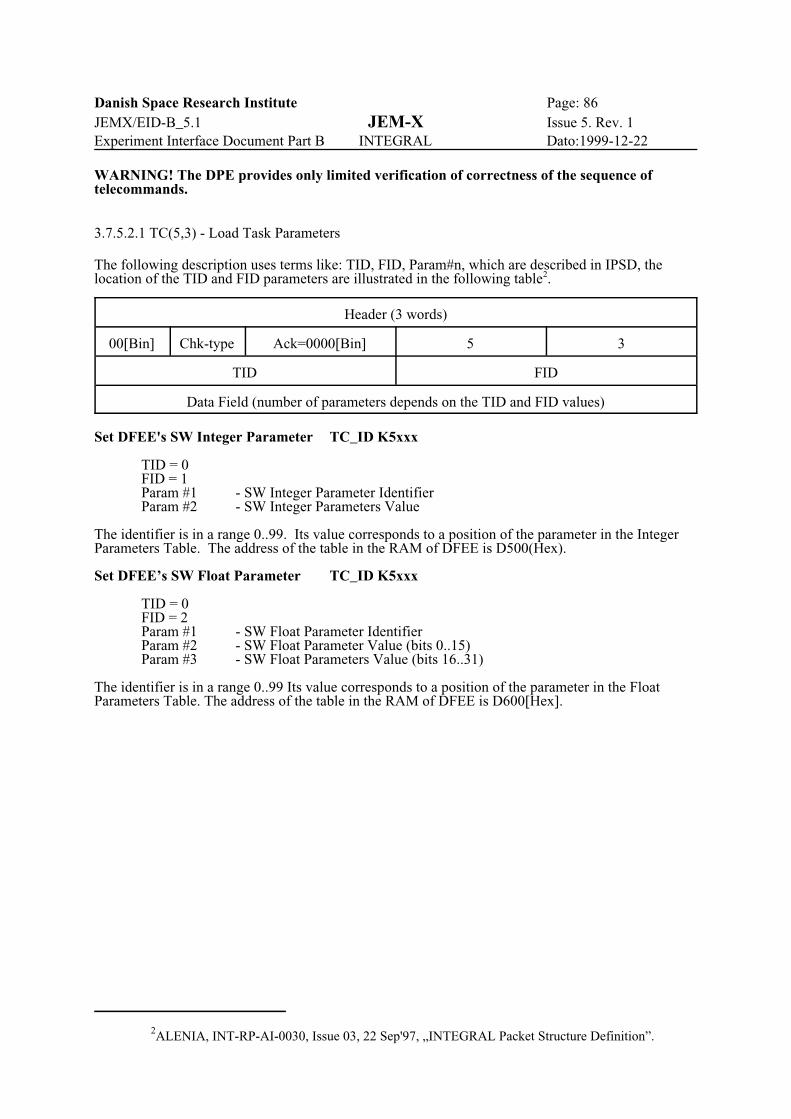
Danish Space Research Institute Page: 86JEMX/EID-B_5.1 JEM-X Issue 5. Rev. 1Experiment Interface Document Part B INTEGRAL Dato:1999-12-22
2ALENIA, INT-RP-AI-0030, Issue 03, 22 Sep'97, „INTEGRAL Packet Structure Definition”.
WARNING! The DPE provides only limited verification of correctness of the sequence oftelecommands.
3.7.5.2.1 TC(5,3) - Load Task Parameters
The following description uses terms like: TID, FID, Param#n, which are described in IPSD, thelocation of the TID and FID parameters are illustrated in the following table2.
Header (3 words)
00[Bin] Chk-type Ack=0000[Bin] 5 3
TID FID
Data Field (number of parameters depends on the TID and FID values)
Set DFEE's SW Integer Parameter TC_ID K5xxx
TID = 0FID = 1Param #1 - SW Integer Parameter IdentifierParam #2 - SW Integer Parameters Value
The identifier is in a range 0..99. Its value corresponds to a position of the parameter in the IntegerParameters Table. The address of the table in the RAM of DFEE is D500(Hex).
Set DFEE’s SW Float Parameter TC_ID K5xxx
TID = 0FID = 2Param #1 - SW Float Parameter IdentifierParam #2 - SW Float Parameter Value (bits 0..15)Param #3 - SW Float Parameters Value (bits 16..31)
The identifier is in a range 0..99 Its value corresponds to a position of the parameter in the FloatParameters Table. The address of the table in the RAM of DFEE is D600[Hex].

Danish Space Research Institute Page: 87JEMX/EID-B_5.1 JEM-X Issue 5. Rev. 1Experiment Interface Document Part B INTEGRAL Dato:1999-12-22
Anode Settings Command TC_ID K5xxx
TID = 0FID = 31Param #1 - HW Setting value
Four Low Significant Bits of Param#1 sets the given anode ON (bit=0) or OFF (bit=1). Theassignment of individual anode to a bit position is the following:
bit 12 - anode 1,bit 13 - anode 2,bit 14 - anode 3,bit 15 - anode 4.
Low Level of Discriminator Setting Command TC_ID K5xxx
TID = 0FID = 32Param#1 - Low Level of Discriminator (range 0..255)
Acceleration HV Setting Command TC_ID K5xxx
TID = 0FID = 33Param#1 - Acceleration HV (range 0..4095)
Drift HV Setting Command TC_ID K5xxx
TID = 0FID = 34Param#1 - Drift HV (range 0..15)
HV Ready Command TC_ID K5xxx
TID = 0FID = 4
HV On Command TC_ID K5xxx
TID = 0FID = 5
HV Off Command TC_ID K5xxx
TID = 0FID = 6
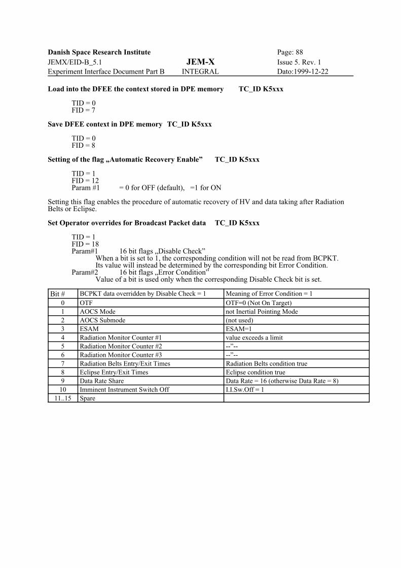
Danish Space Research Institute Page: 88JEMX/EID-B_5.1 JEM-X Issue 5. Rev. 1Experiment Interface Document Part B INTEGRAL Dato:1999-12-22
Load into the DFEE the context stored in DPE memory TC_ID K5xxx
TID = 0FID = 7
Save DFEE context in DPE memory TC_ID K5xxx
TID = 0FID = 8
Setting of the flag „Automatic Recovery Enable” TC_ID K5xxx
TID = 1FID = 12Param #1 = 0 for OFF (default), =1 for ON
Setting this flag enables the procedure of automatic recovery of HV and data taking after RadiationBelts or Eclipse.
Set Operator overrides for Broadcast Packet data TC_ID K5xxx
TID = 1FID = 18Param#1 16 bit flags „Disable Check”
When a bit is set to 1, the corresponding condition will not be read from BCPKT.Its value will instead be determined by the corresponding bit Error Condition.
Param#2 16 bit flags „Error Condition”Value of a bit is used only when the corresponding Disable Check bit is set.
Bit # BCPKT data overridden by Disable Check = 1 Meaning of Error Condition = 10 OTF OTF=0 (Not On Target)1 AOCS Mode not Inertial Pointing Mode2 AOCS Submode (not used)3 ESAM ESAM=14 Radiation Monitor Counter #1 value exceeds a limit5 Radiation Monitor Counter #2 --”--6 Radiation Monitor Counter #3 --”--7 Radiation Belts Entry/Exit Times Radiation Belts condition true8 Eclipse Entry/Exit Times Eclipse condition true9 Data Rate Share Data Rate = 16 (otherwise Data Rate = 8)10 Imminent Instrument Switch Off I.I.Sw.Off = 1
11..15 Spare
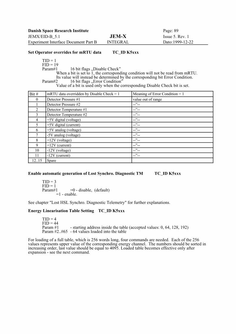
Danish Space Research Institute Page: 89JEMX/EID-B_5.1 JEM-X Issue 5. Rev. 1Experiment Interface Document Part B INTEGRAL Dato:1999-12-22
Set Operator overrides for mRTU data TC_ID K5xxx
TID = 1FID = 19Param#1 16 bit flags „Disable Check”
When a bit is set to 1, the corresponding condition will not be read from mRTU.Its value will instead be determined by the corresponding bit Error Condition.
Param#2 16 bit flags „Error Condition”Value of a bit is used only when the corresponding Disable Check bit is set.
Bit # mRTU data overridden by Disable Check = 1 Meaning of Error Condition = 10 Detector Pressure #1 value out of range1 Detector Pressure #2 --”--2 Detector Temperature #1 --”--3 Detector Temperature #2 --”--4 +5V digital (voltage) --”--5 +5V digital (current) --”--6 +5V analog (voltage) --”--7 -5V analog (voltage) --”--8 +12V (voltage) --”--9 +12V (current) --”--10 -12V (voltage) --”--11 -12V (current) --”--
12..15 Spare
Enable automatic generation of Lost Synchro. Diagnostic TM TC_ID K5xxx
TID = 3FID = 1Param#1 =0 - disable, (default)
=1 - enable.
See chapter "Lost HSL Synchro. Diagnostic Telemetry" for further explanations.
Energy Linearisation Table Setting TC_ID K5xxx
TID = 4FID = 44Param #1 - starting address inside the table (accepted values: 0, 64, 128, 192)Param #2..#65 - 64 values loaded into the table
For loading of a full table, which is 256 words long, four commands are needed. Each of the 256values represents upper value of the corresponding energy channel. The numbers should be sorted inincreasing order, last value should be equal to 4095. Loaded table becomes effective only afterexpansion - see the next command.

Danish Space Research Institute Page: 90JEMX/EID-B_5.1 JEM-X Issue 5. Rev. 1Experiment Interface Document Part B INTEGRAL Dato:1999-12-22
Command - "Expand Energy Linearisation Table" TC_ID K5xxx
TID = 4FID = 45
To be effective the energy linearisation table must be expanded to another table - 4056 8-bit wordslong in which each entry represents energy channel number (0..255) assigned to an energy (0..4095).
Set the Grey Filter TC_ID K5xxx
TID = 4FID = 43Param #1 if in the range 0..31 - indication to the Grey Filter to be used,
if equal to FFFF[Hex] - means that DPE should set Grey Filter automatically (default)
Set the parameters for automatic Grey Filter selection procedure TC_ID K5xxx
TID = 4FID = 46Param #1 - Extra Low Level (default 5%)Param #2 - Normal Low Level (default 20%)Param #3 - Normal High Level (default 50%)Param #4 - Extra High Level (default 80%)
In the current algorithm (since IASW ver.1.27) the value of Extra Low Level is not used, but stillmust be set properly in the command.
Set period of automatic generation of SW Diagnostic reports TC_ID K5xxx
TID = 1FID = 15Param #1 - Period of generation of SW Diagnostic TM Packets expressed as
a number of BCP1 periods (8 sec each). If set to 0 (default) - no automatic reports will be produced.
Set thresholds for Radiation Monitor Count Rates. TC_ID K5xxx
TID = 1FID = 17Param #1 - Higher value (for rad.belts entering) of Radiation Monitor Count Rate #1Param #2 - Lower value (for rad.belts exiting) of Radiation Monitor Count Rate #1Param #3 - Higher value (for rad.belts entering) of Radiation Monitor Count Rate #2Param #4 - Lower value (for rad.belts exiting) of Radiation Monitor Count Rate #2Param #5 - Higher value (for rad.belts entering) of Radiation Monitor Count Rate #3Param #6 - Lower value (for rad.belts exiting) of Radiation Monitor Count Rate #3

Danish Space Research Institute Page: 91JEMX/EID-B_5.1 JEM-X Issue 5. Rev. 1Experiment Interface Document Part B INTEGRAL Dato:1999-12-22
3.7.5.2.2 TC(5,4) - Report Task Parameters
Header (3 words)
00[Bin] Chk-type Ack=0000[Bin] 5 4
TID FID
Data Field (number of parameters depends on the TID and FID values)
TIDs, FIDs and format in most cases are the same as for TC(5,3). Only SW parameters can bequeried, no HW Settings Report is provided with use of TC(5,4). Actual HW Settings are reported inthe housekeeping packets. As a response to TC(5,4) a TM(5,4) packet is generated. Normally oneTC(5,4) generates one TM(5,4), there are two exceptions:- SW Diagnostic (TM(5,4)/TID=1/FID=16) can be produced automatically with a programmedperiod,- HSL Lost Synchro. Diagnostic (TM(5,4)/TID=3/FID=1) can be produced automatically
as a response on the event of losing synchronization.
Report DFEE’s SW Integer Parameters Table
Question: TID = 0FID = 11
Answer: TID = 0FID = 11Param #1..#100- Set of Integer Parameters (1 integer parameter = 1 word)
Report DFEE’s SW Float Parameters Table
Question: TID = 0FID = 12
Answer: TID = 0FID = 12Param #1..#200- Set of Float Parameters (1 float parameter = 2 words)
Report of the flag „Automatic Recovery Enable”
Question: TID = 1FID = 12
Answer: TID = 1FID = 12Param #1 - „Automatic Recovery Enable” flag (0=OFF, 1=ON)
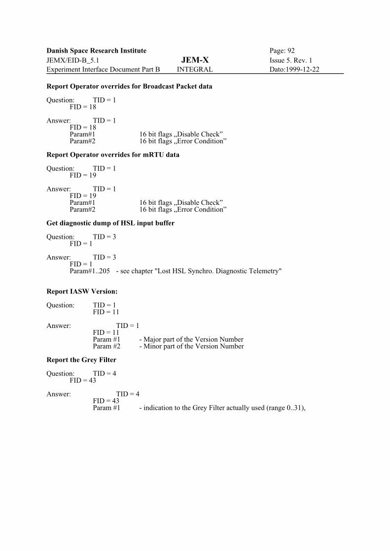
Danish Space Research Institute Page: 92JEMX/EID-B_5.1 JEM-X Issue 5. Rev. 1Experiment Interface Document Part B INTEGRAL Dato:1999-12-22
Report Operator overrides for Broadcast Packet data
Question: TID = 1FID = 18
Answer: TID = 1FID = 18Param#1 16 bit flags „Disable Check”Param#2 16 bit flags „Error Condition”
Report Operator overrides for mRTU data
Question: TID = 1FID = 19
Answer: TID = 1FID = 19Param#1 16 bit flags „Disable Check”Param#2 16 bit flags „Error Condition”
Get diagnostic dump of HSL input buffer
Question: TID = 3FID = 1
Answer: TID = 3FID = 1Param#1..205 - see chapter "Lost HSL Synchro. Diagnostic Telemetry"
Report IASW Version:
Question: TID = 1FID = 11
Answer: TID = 1FID = 11Param #1 - Major part of the Version NumberParam #2 - Minor part of the Version Number
Report the Grey Filter
Question: TID = 4FID = 43
Answer: TID = 4FID = 43Param #1 - indication to the Grey Filter actually used (range 0..31),
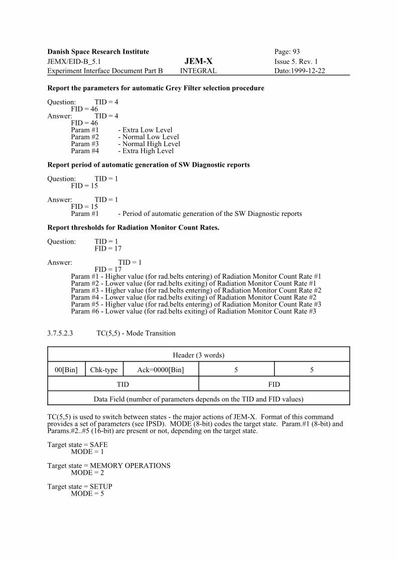
Danish Space Research Institute Page: 93JEMX/EID-B_5.1 JEM-X Issue 5. Rev. 1Experiment Interface Document Part B INTEGRAL Dato:1999-12-22
Report the parameters for automatic Grey Filter selection procedure
Question: TID = 4FID = 46
Answer: TID = 4FID = 46Param #1 - Extra Low LevelParam #2 - Normal Low LevelParam #3 - Normal High LevelParam #4 - Extra High Level
Report period of automatic generation of SW Diagnostic reports
Question: TID = 1FID = 15
Answer: TID = 1FID = 15Param #1 - Period of automatic generation of the SW Diagnostic reports
Report thresholds for Radiation Monitor Count Rates.
Question: TID = 1FID = 17
Answer: TID = 1FID = 17
Param #1 - Higher value (for rad.belts entering) of Radiation Monitor Count Rate #1Param #2 - Lower value (for rad.belts exiting) of Radiation Monitor Count Rate #1Param #3 - Higher value (for rad.belts entering) of Radiation Monitor Count Rate #2Param #4 - Lower value (for rad.belts exiting) of Radiation Monitor Count Rate #2Param #5 - Higher value (for rad.belts entering) of Radiation Monitor Count Rate #3Param #6 - Lower value (for rad.belts exiting) of Radiation Monitor Count Rate #3
3.7.5.2.3 TC(5,5) - Mode Transition
Header (3 words)
00[Bin] Chk-type Ack=0000[Bin] 5 5
TID FID
Data Field (number of parameters depends on the TID and FID values)
TC(5,5) is used to switch between states - the major actions of JEM-X. Format of this commandprovides a set of parameters (see IPSD). MODE (8-bit) codes the target state. Param.#1 (8-bit) andParams.#2..#5 (16-bit) are present or not, depending on the target state.
Target state = SAFEMODE = 1
Target state = MEMORY OPERATIONSMODE = 2
Target state = SETUPMODE = 5

Danish Space Research Institute Page: 94JEMX/EID-B_5.1 JEM-X Issue 5. Rev. 1Experiment Interface Document Part B INTEGRAL Dato:1999-12-22
Target state = DATA TAKINGMODE = 10Param #1 = 0 (not used)Param #2 = Primary Format CodeParam #3 = Secondary Format Code[ Param #4 = Grey Filter for switching to Secondary Format ][ Param #5 = Grey Filter for switching back to Primary Format ]
Parameters #4 and #5 are optional. Grey Filter threshold levels will remain unchanged if parametersare missing.The Grey Filter thresholds should comply: Param#4 < Param#5.
Target state = CALIBRATIONMODE = 20Param #1 = 0 (not used)Param #2 = Number of events per calibration level
Target state = DIAGNOSTIC DUMPMODE = 40Param #1 = 0 (not used)Param #2 = Number of events to be dumped
Target state = DATA TAKING (test data mode)MODE = 11
When this state is commanded, the DFEE will be set in DATA TAKING and the DPE will letthe event data on the HSL pass through to the telemetry without modifications. This data mode couldbe usefull also in-flight if anomalies occur in the instrument.
Target state = CALIBRATION (test data mode)MODE = 21Param #1 = 0 (not used)Param #2 = Number of events per calibration level
Target state = DIAGNOSTIC DUMP (test data mode)MODE = 41Param #1 = 0 (not used)Param #2 = Number of events to be dumped
For coding of Primary and Secondary Imaging Formats use numerical codes:
Code of the Format Format-------------------------------------------------------
1 Full Imaging2 Spectral-timing3 Restricted Imaging4 Timing5 Spectrum90 Test
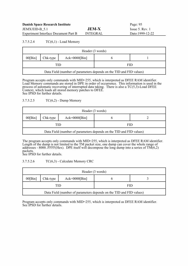
Danish Space Research Institute Page: 95JEMX/EID-B_5.1 JEM-X Issue 5. Rev. 1Experiment Interface Document Part B INTEGRAL Dato:1999-12-22
3.7.5.2.4 TC(6,1) - Load Memory
Header (3 words)
00[Bin] Chk-type Ack=0000[Bin] 6 1
TID FID
Data Field (number of parameters depends on the TID and FID values)
Program accepts only commands with MID=255, which is interpreted as DFEE RAM identifier. Load Memory commands are stored in DPE in order of occurrence. This information is used in theprocess of automatic recovering of interrupted data taking. There is also a TC(5,3)-Load DFEEContext, which loads all stored memory patches to DFEE.See IPSD for further details.
3.7.5.2.5 TC(6,2) - Dump Memory
Header (3 words)
00[Bin] Chk-type Ack=0000[Bin] 6 2
TID FID
Data Field (number of parameters depends on the TID and FID values)
The program accepts only commands with MID=255, which is interpreted as DFEE RAM identifier. Length of the dump is not limited to the TM packet size, one dump can cover the whole range ofaddresses - 8000..FFFF(Hex). DPE itself will decompose the long dump into a series of TM(6,2)packets.See IPSD for further details.
3.7.5.2.6 TC(6,3) - Calculate Memory CRC
Header (3 words)
00[Bin] Chk-type Ack=0000[Bin] 6 3
TID FID
Data Field (number of parameters depends on the TID and FID values)
Program accepts only commands with MID=255, which is interpreted as DFEE RAM identifier.See IPSD for further details.

Danish Space Research Institute Page: 96JEMX/EID-B_5.1 JEM-X Issue 5. Rev. 1Experiment Interface Document Part B INTEGRAL Dato:1999-12-22
3.7.5.2.7 TC(9,1) - Report TM Packet Generation Status
Header (3 words)
00[Bin] Chk-type Ack=0000[Bin] 9 1
TID FID
Data Field (number of parameters depends on the TID and FID values)
The following TM Packets can be controlled: TM(5,4), TM(6,2), TM(6,3), TM(9,1).See IPSD for further details.
3.7.5.2.8 TC(9,4) - Enable Generation of Specific TM Packets See IPSD for details.
3.7.5.2.9 TC(9,5) - Disable Generation of Specific TM Packets See IPSD for details.
3.7.5.2.10 TC(13,1) - Test command This is a No Operation Command. Its only action is incrementing of the counter of telecommandsreceived.
3.7.5.2.11 TC(15,1) - Broadcast Packet The Broadcast Packet (BCPKT) is analyzed as soon as it is received by DPE. Some specific contentof the BCPKT can cause a so called "shutdown" - stopping of data taking. Automatic recovery ofdata taking is possible, but only if the flag "Automatic Recovery Enabled" is set.
The reaction to the On Target Flag is performed independently of the value of "Automatic RecoveryEnabled" flag. See chapters: "Shutdown/Recovery scheme" and "Analysis of Eclipse and RadiationBelts Entry/Exit Times" for further details.
Data Rate Share. This value is used in the algorithm for calculating of the Grey Filter, used tomoderate the JEM-X data rate. OTF-On Target Flag. The OTF is used in combination with the Pointing ID to determine the start of a new observation. Wewill recognize the acquicsition of a new target (distinct from any temporary flickering of the OnTarget Flag during a pointing) by the following logic: Whenever the (validated) On Target Flagmakes a transition from zero to one the current value of the Pointing ID parameter in the BroadcastPacket will be compared with the Pointing ID value stored on the previous occasion of the On TargetFlag zero-to-one transition. If the stored value and the current value of the Pointing ID is the same, noaction will be taken by the IASW. If the values are different, then the DPE and the DFEE data bufferswill be flushed and the new value of the Pointing ID will be stored for future reference.
AOCS Mode. When equal to IPM (Inertial Pointing Mode) - enables interpretation of OTF (asdescribed above). For all other values the content of the OTF is ignored.
AOCS Sub Mode. Ignored.
Radiation Monitor Count Rate (#1,#2,#3). If any of the three counters exceeds the TBD threshold(adjustable individually for each of them through a Load Task Parameter TC(5,3)(TID=1, FID=17)),it is interpreted as the entrance into the radiation belts. Exit from radiation belts is assumed when allcounters are below thresholds. Thresholds defining exit from radiation belts will be lower than thosedefining entering into radiation belts (hysteresis). Interpretation of these data is affected by DRMCflag.Entrance into the area of high radiation will result in stopping data taking in soft mode, switching offHV, and setting DFEE to Safe mode.

Danish Space Research Institute Page: 97JEMX/EID-B_5.1 JEM-X Issue 5. Rev. 1Experiment Interface Document Part B INTEGRAL Dato:1999-12-22
DRMC-Disregard Radiation Monitor Count Rates. Radiation Monitor Count Rates are consideredvalid only when DRMC=0 (Disregard Radiation Monitor Count Rates). Otherwise (DRMC=1)Radiation Monitor Count Rates are assumed low.
ESAM-Emergency Safe Acquisition Mode. Reaction on this signal as in case of high radiation.
Instrument Imminent Switch-Off. Data taking is stopped in soft mode, HV is turned off. NextDPE stores context of DFEE, to be able to recover data taking. DFEE is left in Safe state, waiting forturning off the low voltage supply.
Ground Station Hand-Over Flag. Ignored.
Pointing ID. Used in the On Target Flag logic as described above.
Radiation Belts Crossing Start Time, Radiation Belts Crossing Exit Time and Eclipse EntryTime. All valid time-type fields (not equal to zero) from BCPKT will be stored separately. Thepurpose is to have good data for comparison with the current OBT in case of interrupted connectionEarth - S/C. Time-type data are recalculated at the very beginning from BCPKT format to 48-bitformat. The program uses internally only 48-bit format coding for On Board Time.
Entrance into the radiation belt will result in stopping data taking in soft mode, switching off HV, and setting DFEE to SAFE.
At exit from the radiation belt the DFEE state prior to the entry may be be restored autonomously -this assumes that the “Autonomous Recovery Flag has been set on - the default value for this flag isoff.
When entering into eclipse region, data taking is stopped in soft mode and the HV is turned off. Next, the DPE stores the context of DFEE, to be able to recover data taking after the eclipse. The DFEE is left in SAFE state, waiting for the turn-off of the low voltage.
Recovery after eclipse exit takes place under ground control.
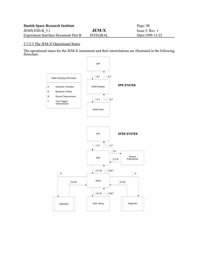
Danish Space Research Institute Page: 98JEMX/EID-B_5.1 JEM-X Issue 5. Rev. 1Experiment Interface Document Part B INTEGRAL Dato:1999-12-22
OFF
IASW Standby
IASW Active
G,T G,T
G,T G,T
G,T G,TState Changing Commands
A Automatic Transition
B Broadcast Packet
G Ground Telecommand
T Time TaggedTelecommand
SafeMemory
Patch/Dump
Setup
Calibration DiagnosticData Taking
G
G,A,B
G
G,A,B
G,B,TG,T,B
G,B,TG,T,B
G,T
G,T,B
OFF
DPE STATES
DFEE STATES
3.7.5.3 The JEM-X Operational States
The operational states for the JEM-X instrument and their interrelations are illustrated in the followingflowchart.
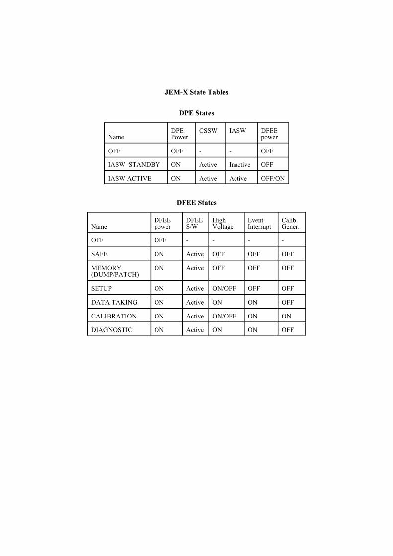
JEM-X State Tables
DPE States
NameDPEPower
CSSW IASW DFEEpower
OFF OFF - - OFF
IASW STANDBY ON Active Inactive OFF
IASW ACTIVE ON Active Active OFF/ON
DFEE States
NameDFEEpower
DFEES/W
HighVoltage
EventInterrupt
Calib.Gener.
OFF OFF - - - -
SAFE ON Active OFF OFF OFF
MEMORY(DUMP/PATCH)
ON Active OFF OFF OFF
SETUP ON Active ON/OFF OFF OFF
DATA TAKING ON Active ON ON OFF
CALIBRATION ON Active ON/OFF ON ON
DIAGNOSTIC ON Active ON ON OFF
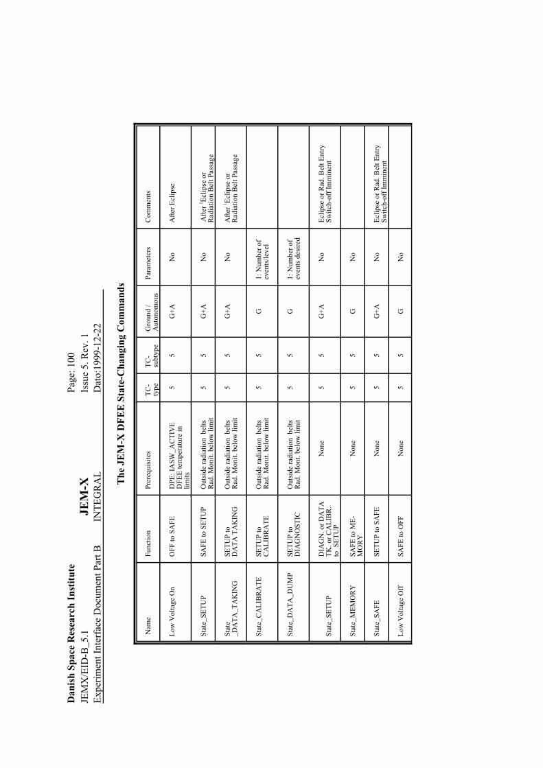
Dan
ish
Spac
e R
esea
rch
Inst
itut
ePa
ge: 1
00JE
MX
/EID
-B_5
.1JE
M-X
Issu
e 5.
Rev
. 1E
xper
imen
t Int
erfa
ce D
ocum
ent P
art B
INT
EG
RA
LD
ato:
1999
-12-
22
The
JE
M-X
DF
EE
Sta
te-C
hang
ing
Com
man
ds
Nam
eFu
ncti
onPr
ereq
uisi
tes
TC
-ty
peT
C-
subt
ype
Gro
und
/A
uton
omou
sPa
ram
eter
sC
omm
ents
Low
Vol
tage
On
OFF
to S
AFE
DPE
: IA
SW_A
CT
IVE
D
FEE
tem
pera
ture
inli
mit
s
55
G+
AN
oA
fter
Ecl
ipse
Stat
e_SE
TU
PSA
FE to
SE
TU
PO
utsi
de r
adia
tion
bel
tsR
ad. M
onit
. bel
ow li
mit
55
G+
AN
o A
fter
1 Ecl
ipse
or
Rad
iati
on B
elt P
assa
ge
Stat
e_D
AT
A_T
AK
ING
SET
UP
to
DA
TA
TA
KIN
GO
utsi
de r
adia
tion
bel
tsR
ad. M
onit
. bel
ow li
mit
55
G+
AN
oA
fter
1 Ecl
ipse
or
Rad
iati
on B
elt P
assa
ge
Stat
e_C
AL
IBR
AT
ESE
TU
P to
CA
LIB
RA
TE
Out
side
rad
iati
on b
elts
Rad
. Mon
it. b
elow
lim
it5
5G
1: N
umbe
r of
even
ts/l
evel
Stat
e_D
AT
A_D
UM
PSE
TU
P to
DIA
GN
OST
ICO
utsi
de r
adia
tion
bel
tsR
ad. M
ont.
belo
w li
mit
55
G1:
Num
ber
of
even
ts d
esir
ed
Stat
e_SE
TU
PD
IAG
N. o
r D
AT
AT
K. o
r C
AL
IBR
. to
SE
TU
P
Non
e5
5G
+A
No
Ecl
ipse
or
Rad
. Bel
t Ent
rySw
itch
-off
Im
min
ent
Stat
e_M
EM
OR
YSA
FE to
ME
-M
OR
YN
one
55
GN
o
Stat
e_SA
FESE
TU
P to
SA
FEN
one
55
G+
AN
oE
clip
se o
r R
ad. B
elt E
ntry
Swit
ch-o
ff I
mm
inen
t
Low
Vol
tage
Off
SAFE
to O
FFN
one
55
GN
o

Danish Space Research Institute Page: 101JEMX/EID-B_5.1 JEM-X Issue 5. Rev. 1Experiment Interface Document Part B INTEGRAL Dato:1999-12-22
3.7.6 TC parameter description
List of DFEE integer software parameters (number refers to position in int-parameter block)
0 to 33 Analog channel offset values A substantial voltage offset is imposed on each of 34 analog channels in order to beable to handle correctly the negative signals resulting from the use of the capacitivereadout. These offset must be removed from the signals on-board before they can beused in the calculation of event positions.
34 Calibration FrequencyThis parameter controls the frequency of the electronic calibration pulses.
35 Anode upper limitThe most important particle event rejection criterion is the upper limit for the anodepulse amplitude.
36 High voltage Cut off count rateThe count rate limit for software controlled High Voltage switch-off.
List of DFEE float software parameters (number refers to position in float-parameter block)
0 Veto reject levelThe maximum allowable value for the ratio of the signal from the veto electrode tothat of the anode (Anode Slow signal).
1 Risetime high limitThe maximum allowable value for the ratio of the signal in the Fast Anode chain tothat of the anode (Anode Slow signal).
2 Risetime low limitThe minimum allowable value for the ratio of the signal in the Fast Anode chain tothat of the anode (Anode Slow signal).
3 Back plane high limitThe maximum allowable value for the ratio of the sum of the signals from thebackplane electrodes to that of the anode (Anode Slow signal).
4 Back plane low limitThe minimum allowable value for the ratio of the sum of the signals from thebackplane electrodes to that of the anode (Anode Slow signal).
5 Cathode high limitThe maximum allowable value for the ratio of the signal from the veto electrode tothat of the anode (Anode Slow signal).
6 Cathode low limitThe minimum allowable value for the ratio of the sum of the signals from thecathode electrodes to that of the anode (Anode Slow signal).
7 Back plane low hit levelThe lower threshold for a back plane signal to be counted as a valid “hit”.
8 Back plane high hit levelThe upper threshold for a back plane signal to be accepted as a valid “hit”.
9 Back plane energy cutThe upper threshold for the sum of the back plane signals.
10 Cathode low hit levelThe lower threshold for a cathode signal to be counted as a valid “hit”.
11 Cathode high hit levelThe upper threshold for a cathode signal to be accepted as a valid “hit”.
12 Cathode energy cutThe upper threshold for the sum of the cathode signals.
13 to 47 Analog channel gain values Each of 34 analog channels will have a slightly different gain value. These gaindifferences must be removed from the signals on-board before they can be used in the calculation of event positions.
All the above parameters are “Engineering” parameters which may need to be adjusted during theverification phase - but only in case of anomalies may they need readjustment later in the flight.
All Hardware parameters and single Software parameters are directly adjustable using TC(5,3)commands. Multiple adjustments af larger sets of parameters can be handled by the DFEE memory

Danish Space Research Institute Page: 102JEMX/EID-B_5.1 JEM-X Issue 5. Rev. 1Experiment Interface Document Part B INTEGRAL Dato:1999-12-22
upload commands. DFEE memory upload commands are, however, not in accordance with the PSDas these commands are not memory load commands proper. The DFEE memory is only accessiblethrough commands via the DPE.
The only HW or SW parameters controlled for every observation are the Primary and Secondary dataformats. All other parameters can be considered static after initial adjustment during the commissio-ning phase.

Danish Space Research Institute Page: 103JEMX/EID-B_5.1 JEM-X Issue 5. Rev. 1Experiment Interface Document Part B INTEGRAL Dato:1999-12-22
3.7.7 TM Packet Structure and Content
3.7.7.1 TM allocation management
The JEM-X software will seek to optimize the usage of the available telemetry. The DPE IASW willinterrogate the Broadcast Packet for the current TM allocation. Nominally, the TM allocation is 18packets per polling cycle in total for the two JEM-X instruments early in the mission (at solarmaximum conditions) and 16 packets per cycle later in the mission (at solar min). Each JEM-Xinstrument will transmit one HK-packet per polling cycle as long as the corresponding DPE ispowered on, but otherwise the two instruments may be set up with different packet rates as long as thetotal allocation is respected.
The packet length is 440 bytes. The packet header occupies 6 bytes and the terminating CRC occupies2 bytes. This leaves 432 bytes or 216 words per packet for the data field.
Prior to a new observation each JEM-X unit will be given a telemetry allocation and also instructedabout which telemetry formats to use. The typical situation will be that both units are requested to usethe “Full Imaging Format” as the primary format. Then, as the secondary format, which will be usedif the count rate exceeds what can be handled in the full format, one unit may be set up to use“Restricted Imaging”, the other “Spectral Timing”. Should the count rate exceed also the capacity ofthe secondary format, then the grey filtering process will be activated.
Grey Filtering
If the input data rate exceeds the rate at which data can be transmitted the DPE software willautonomously select an alternative format or, if the telemetry capacity problem persists for thealternative format, activate the “grey filtering” event rejection process in the DFEE, whereby a certainfraction of the DFEE input triggers are rejected. The grey filter process can operate with 32 differenttransmission fractions. The 32 filters are numbered from 0 to 31, and the filter transmission fraction,F, is calculated as:
F = (N+1) / 32
where N is the filter number.

Danish Space Research Institute Page: 104JEMX/EID-B_5.1 JEM-X Issue 5. Rev. 1Experiment Interface Document Part B INTEGRAL Dato:1999-12-22
3.7.7.2 Format for time stamping of the telemetry packets.
Time information is given at the beginning of each packet. A 40 bit format is used beginning in bit 8of the first word. The least significant bit (of the third word) is counting in units of 1/65536 s. In thisway the least significant bit of the second word will be counting in units of 1 s, making the formatcompatible in this respect with a standard, two-word, data field header.
The precision of the timing of the individual X-ray events in JEM-X is 1/8192 s. Therefore the leastsignificant 3 bits of the 40 bit time should be considered as spare bits and are not to be used in thedata analysis.
Packet Header
Version no.[3]
type[1]
flag
[1]
APID [11]
sequ.fl.[2] sequence count [14]
packet length [16]
Data Field Header
packet type [4] subtype[4] Note: NONSTANDARD time [8] (unit 65536 s)
time [16] (unit 1 s)
time [13] (unit 1/8192 s) spare [3]
Data Field
data 215*[16]
JEM-X Science-TM packet header layout with nonstandard Data Field Header.
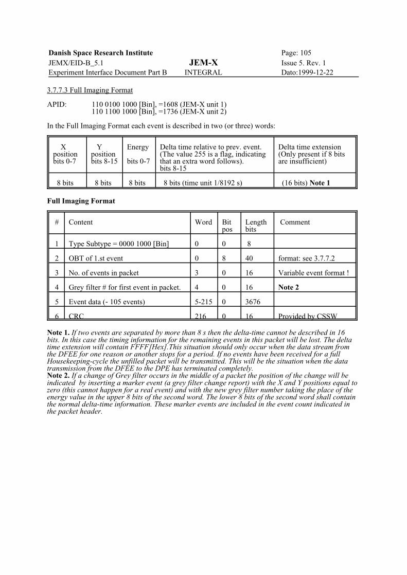
Danish Space Research Institute Page: 105JEMX/EID-B_5.1 JEM-X Issue 5. Rev. 1Experiment Interface Document Part B INTEGRAL Dato:1999-12-22
3.7.7.3 Full Imaging Format
APID: 110 0100 1000 [Bin], =1608 (JEM-X unit 1)110 1100 1000 [Bin], =1736 (JEM-X unit 2)
In the Full Imaging Format each event is described in two (or three) words:
Xpositionbits 0-7
Ypositionbits 8-15
Energy
bits 0-7
Delta time relative to prev. event.(The value 255 is a flag, indicatingthat an extra word follows). bits 8-15
Delta time extension(Only present if 8 bitsare insufficient)
8 bits 8 bits 8 bits 8 bits (time unit 1/8192 s) (16 bits) Note 1
Full Imaging Format
# Content Word Bitpos
Lengthbits
Comment
1 Type Subtype = 0000 1000 [Bin] 0 0 8
2 OBT of 1.st event 0 8 40 format: see 3.7.7.2
3 No. of events in packet 3 0 16 Variable event format !
4 Grey filter # for first event in packet. 4 0 16 Note 2
5 Event data (-105 events) 5-215 0 3676
6 CRC 216 0 16 Provided by CSSW
Note 1. If two events are separated by more than 8 s then the delta-time cannot be described in 16bits. In this case the timing information for the remaining events in this packet will be lost. The deltatime extension will contain FFFF[Hex].This situation should only occur when the data stream fromthe DFEE for one reason or another stops for a period. If no events have been received for a fullHousekeeping-cycle the unfilled packet will be transmitted. This will be the situation when the datatransmission from the DFEE to the DPE has terminated completely.Note 2. If a change of Grey filter occurs in the middle of a packet the position of the change will beindicated by inserting a marker event (a grey filter change report) with the X and Y positions equal tozero (this cannot happen for a real event) and with the new grey filter number taking the place of theenergy value in the upper 8 bits of the second word. The lower 8 bits of the second word shall containthe normal delta-time information. These marker events are included in the event count indicated inthe packet header.

Danish Space Research Institute Page: 106JEMX/EID-B_5.1 JEM-X Issue 5. Rev. 1Experiment Interface Document Part B INTEGRAL Dato:1999-12-22
3.7.7.4 Restricted Imaging Format
APID: 110 0101 1000 [Bin] =1624 (JEM-X unit 1)110 1101 1000 [Bin] =1752 (JEM-X unit 2)
The restricted imaging format may be used when the count rate exceeds the value which can betransmitted using the full imaging format. In this format the timing information for the individualevents is discarded. As compensation, count rate packets will be generated whenever the restrictedimaging format is in use. The countrate packet is described in section 3.7.7.5.
When the restricted imaging format is in use, about 2580 events (TBC) are collected in a buffer in theDPE. The events in the buffer are sorted according to their position in the image, using as a key theinteger value: 256X+Y. (Both X and Y are scaled to the range 1 to 255).
The image data are then transmitted in 8 TM-packets. For the first event in each packet the full X/Yposition is given, and for the following events only the distance between event positions in the 65536position array. The delta-positions are encoded in 5 bits. In cases where the 5 bits do not suffice, anadditional 8 bit word is added. (Note that the value 31 in the 5 bit delta position is not a delta-valuebut a flag indicating that an ekstra 8 bit word follows). If even the 8 bit extension does not suffice tobridge the gap to the next event position a second, 16-bit extension word will be used.
For each event a 3 bit energy value is also given. The 3 bit energy values are derived from the 8 bitvalues used in the full imaging and spectral-timing formats.
Event format in Restricted Imaging
Delta position())
Energy Delta pos. extension ()’) Only present if 5 bits doesnot suffice. () is set to 31)
2. Delta position extensionOnly present if 8 bits doesnot suffice. ()’ is set to 255)
5 bits 3 bits (8 bits) (16 bits)
A timeout function for the collection of the 2580 events (TBC) needed for one image will be initiatedwhenever data collection for a new image is started. If, after 32 seconds, less than the required numberof events has been collected, the available image data will anyway be transmitted. This functionassures that we do not wait indefinitely transmitting the last part of the data if the event data streamfrom the detector or from the DFEE is interrupted. Under normal circumstances the restricted imagingwill only be invoked when the countrate exceeds the capacity of the full imaging format, -100counts/s.

Danish Space Research Institute Page: 107JEMX/EID-B_5.1 JEM-X Issue 5. Rev. 1Experiment Interface Document Part B INTEGRAL Dato:1999-12-22
Restricted Imaging Format
# Content Word Bitpos
Lengthbits
Comment
1 Type Subtype=0001 1000 [Bin] 0 0 8
2 OBT of first event in image 0 8 40 OBT format: see 3.7.7.2
3 Length of time interval coveredby image
3 0 16 precision: 1/2048 s
4 No. of events in packet 4 0 16
5 Grey filter, first event in image. 5 0 16 Note 1
6 Grey filter, last event in image 6 0 16 Note 1
7 XY pos for first event in packet. 7 0 16 8 bits X pos +8 bits Y pos.
8 XY pos for last event in packet. 8 0 16 8 bits X pos +8 bits Y pos
9 Sequence # of packet in image(8000[hex] added for last packet)
9 0 16
10Event data (-320 events) 10-215 0 3296
11CRC 216 0 16 Provided by CSSW
Note 1. There is no way to indicate in this Restricted Imaging Format which events in the image havebeen recorded with a specific greyfilter value. However, in the corresponding countrate packet thetime-evolution of the grey filter values can be followed.

Danish Space Research Institute Page: 108JEMX/EID-B_5.1 JEM-X Issue 5. Rev. 1Experiment Interface Document Part B INTEGRAL Dato:1999-12-22
3.7.7.5 Count Rate Format
APID: 110 0111 1000 [Bin] = 1656 (JEM-X unit 1)110 1111 1000 [Bin] = 1784 (JEM-X unit 2)
The countrate format cannot be used by itself. It will be automatically invoked when the restrictedimaging or one of the two spectral formats are required. The countrate packets will appear in betweenthe packets of the invoking format.Each time bin is 125 ms wide.
In order to assure that the time bins in a count rate packet always align with other data (spectratransmitted in spectral format and time bins in other count rate packet blocks) the time bins willalways begin when the DFEE time counter has zeroes in the lower 10 bits. This happens every 125ms. The DFEE time counter is reset via a logic based on the BCP2 pulse, and therefore there will be afixed relation between the OBT and all time bin start times.
Countrate Format
# Content Word Bitpos
Lengthbits
Comment
1 Type Subtype = 0011 1000 [Bin] 0 0 8
2 OBT of first time bin 0 8 40 format: see 3.7.7.2Lower 14 bits always 0!
3 8 greyfilter specifiers (see below) 3 0 128
4 # of time bins in this packet 11 0 16 .
5 Count rate in first time bin 12 0 16
6 Delta-count rates (see text) 13-215 0 3248
7 CRC 216 0 16 Provided by CSSW
The delta-countrates in the packet are coded into 8 bits (-127 to +126 with negative numbers in two-complement notation). If 8 bits does not suffice for a particular time bin, then a marker of +127 isplaced in the first 8 bit followed by the full 16 bit countrate (not the difference!). The 16 bit value isplaced in the buffer without any gap, even if it is not word aligned.
Format for greyfilter specifiers
Bit pos Length(bits)
Content
0 5 Greyfilter number
5 11 Time bin number in packet where greyfilter takes effectThe time bin number will allways be zero for the first specifier. The subsequent specifiers are only valid if time bin number is nonzero

Danish Space Research Institute Page: 109JEMX/EID-B_5.1 JEM-X Issue 5. Rev. 1Experiment Interface Document Part B INTEGRAL Dato:1999-12-22
3.7.7.6 Spectral Timing Format
APID: 110 0101 0000 [Bin] = 1616 (JEM-X unit 1)110 1101 0000 [Bin] = 1744 (JEM-X unit 2)
In this format the imaging data for each event are discarded. The format is only suited for observa-tions where one, strong source dominates the scene. The time difference between events are encodedin 8 bits. If that happens to be insufficient a value of 255 is given in the 8 bits and a full 16 bit wordis added to encode the time difference. The energy information is encoded in 8 bits.
Event format in Spectral/Timing
Energy Delta time (0 to 254) Delta time extension. (If the delta time is larger than 254 )
8 bits 8 bits (time unit 1/8192 s) (16 bits)
Spectral/Timing Format
# Content Word Bitpos
Lengthbits
Comment
1 Type Subtype = 0001 0000[Bin] 0 0 8
2 OBT of first event 0 8 40 format: see 3.7.7.2
3 No. of events in packet 3 0 16 No. of events is variable dueto variable event format
4 Grey filter # for first event 4 0 16 Note 1
5 Event data (-210 events) 5-215 0 3376
6 CRC 216 0 16 Provided by CSSW
Note 1. If a change of Grey filter occurs in the middle of a packet the position of the change will beindicated by inserting a marker event with an energy value of zero and the new grey filter numberwill be inserted in place of the Delta time. Such marker events will be included in the event countindicated in the packet header.
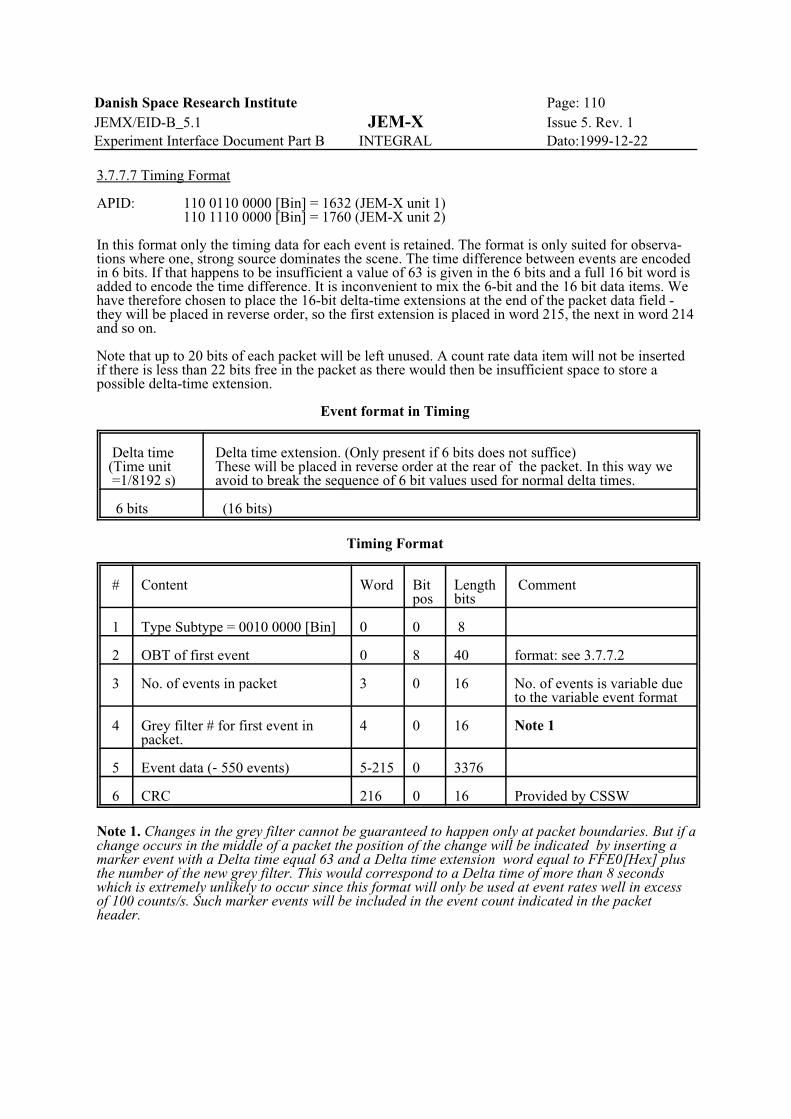
Danish Space Research Institute Page: 110JEMX/EID-B_5.1 JEM-X Issue 5. Rev. 1Experiment Interface Document Part B INTEGRAL Dato:1999-12-22
3.7.7.7 Timing Format
APID: 110 0110 0000 [Bin] = 1632 (JEM-X unit 1)110 1110 0000 [Bin] = 1760 (JEM-X unit 2)
In this format only the timing data for each event is retained. The format is only suited for observa-tions where one, strong source dominates the scene. The time difference between events are encodedin 6 bits. If that happens to be insufficient a value of 63 is given in the 6 bits and a full 16 bit word isadded to encode the time difference. It is inconvenient to mix the 6-bit and the 16 bit data items. Wehave therefore chosen to place the 16-bit delta-time extensions at the end of the packet data field -they will be placed in reverse order, so the first extension is placed in word 215, the next in word 214and so on.
Note that up to 20 bits of each packet will be left unused. A count rate data item will not be insertedif there is less than 22 bits free in the packet as there would then be insufficient space to store apossible delta-time extension.
Event format in Timing
Delta time(Time unit =1/8192 s)
Delta time extension. (Only present if 6 bits does not suffice) These will be placed in reverse order at the rear of the packet. In this way we avoid to break the sequence of 6 bit values used for normal delta times.
6 bits (16 bits)
Timing Format
# Content Word Bitpos
Lengthbits
Comment
1 Type Subtype = 0010 0000 [Bin] 0 0 8
2 OBT of first event 0 8 40 format: see 3.7.7.2
3 No. of events in packet 3 0 16 No. of events is variable dueto the variable event format
4 Grey filter # for first event inpacket.
4 0 16 Note 1
5 Event data (-550 events) 5-215 0 3376
6 CRC 216 0 16 Provided by CSSW
Note 1. Changes in the grey filter cannot be guaranteed to happen only at packet boundaries. But if achange occurs in the middle of a packet the position of the change will be indicated by inserting amarker event with a Delta time equal 63 and a Delta time extension word equal to FFE0[Hex] plusthe number of the new grey filter. This would correspond to a Delta time of more than 8 secondswhich is extremely unlikely to occur since this format will only be used at event rates well in excessof 100 counts/s. Such marker events will be included in the event count indicated in the packetheader.

Danish Space Research Institute Page: 111JEMX/EID-B_5.1 JEM-X Issue 5. Rev. 1Experiment Interface Document Part B INTEGRAL Dato:1999-12-22
3.7.7.8 Spectrum Format
APID: 110 0110 1000 [Bin] = 1640 (JEM-X unit 1)110 1110 1000 [Bin] = 1768 (JEM-X unit 2)
In this format only the energy information is transmitted. The format is only suited for observations whereone, strong source dominates the scene. Spectra with 64 energy channels are transmitted at a rate of 8spectra per second. The 6-bit channel numbers are derived from the 8 bit energy value used in the FullImaging format by masking away the lower two bits. The 125 ms integration time intervals are alignedwith the time bins used in the Count Rate format (see 3.7.7.5).
The content of each of the 64 spectral channels are allocated 4 bits in this format. Should a channel containmore than 14 counts the 4-bit value will be set to 15, and the full count value (truncated to 8 bits ifnecessary) will be placed in the next free 8 bit overflow field of this spectrum block.
Spectrum Format
# Content Word Bit pos Lengthbits
Comment
1 Type Subtype = 0010 1000 [Bin] 0 0 8
1 OBT of start of first spectrum 0 8 40 format: see 3.7.7.2
2 # of spectra in packet 3 0 16 May be less than 10 forlast packet.
3 Spectrum Block #1 4 0 336
4 Spectrum Block #2 25 0 336
5 Spectrum Block #3 46 0 336
6 Spectrum Block #4 67 0 336
7 Spectrum Block #5 88 0 336
8 Spectrum Block #6 109 0 336
9 Spectrum Block #7 130 0 336
10Spectrum Block #8 151 0 336
11Spectrum Block #9 172 0 336
12Spectrum Block #10. 193 0 336
23CRC 216 0 16 Provided by CSSW

Danish Space Research Institute Page: 112JEMX/EID-B_5.1 JEM-X Issue 5. Rev. 1Experiment Interface Document Part B INTEGRAL Dato:1999-12-22
Format for each spectrum block
# Content Word Bitpos
Lengthbits
Comment
1 Grey filter for first event in spectrum 0 0 16
2 64 channel energy spectrum (4 bits/ch) 1 - 16 0 256
3 8 overflow fields (8 bits each) 17 - 20 0 64
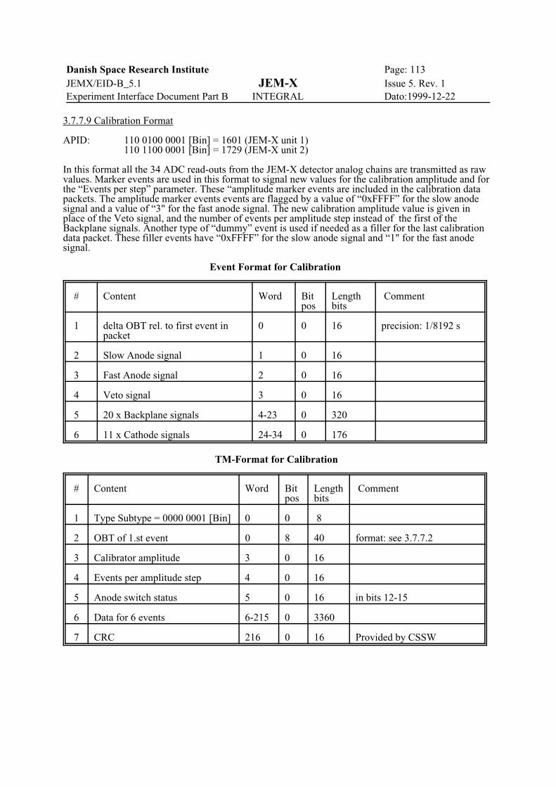
Danish Space Research Institute Page: 113JEMX/EID-B_5.1 JEM-X Issue 5. Rev. 1Experiment Interface Document Part B INTEGRAL Dato:1999-12-22
3.7.7.9 Calibration Format
APID: 110 0100 0001 [Bin] = 1601 (JEM-X unit 1)110 1100 0001 [Bin] = 1729 (JEM-X unit 2)
In this format all the 34 ADC read-outs from the JEM-X detector analog chains are transmitted as rawvalues. Marker events are used in this format to signal new values for the calibration amplitude and forthe “Events per step” parameter. These “amplitude marker events are included in the calibration datapackets. The amplitude marker events events are flagged by a value of “0xFFFF” for the slow anodesignal and a value of “3" for the fast anode signal. The new calibration amplitude value is given inplace of the Veto signal, and the number of events per amplitude step instead of the first of theBackplane signals. Another type of “dummy” event is used if needed as a filler for the last calibrationdata packet. These filler events have “0xFFFF” for the slow anode signal and “1" for the fast anodesignal.
Event Format for Calibration
# Content Word Bitpos
Lengthbits
Comment
1 delta OBT rel. to first event inpacket
0 0 16 precision: 1/8192 s
2 Slow Anode signal 1 0 16
3 Fast Anode signal 2 0 16
4 Veto signal 3 0 16
5 20 x Backplane signals 4-23 0 320
6 11 x Cathode signals 24-34 0 176
TM-Format for Calibration
# Content Word Bitpos
Lengthbits
Comment
1 Type Subtype = 0000 0001 [Bin] 0 0 8
2 OBT of 1.st event 0 8 40 format: see 3.7.7.2
3 Calibrator amplitude 3 0 16
4 Events per amplitude step 4 0 16
5 Anode switch status 5 0 16 in bits 12-15
6 Data for 6 events 6-215 0 3360
7 CRC 216 0 16 Provided by CSSW

Danish Space Research Institute Page: 114JEMX/EID-B_5.1 JEM-X Issue 5. Rev. 1Experiment Interface Document Part B INTEGRAL Dato:1999-12-22
3.7.7.10 Diagnostic Dump Format
APID: 110 0100 0010 [Bin] = 1602 (JEM-X unit 1)110 1100 0010 [Bin] = 1730 (JEM-X unit 2)
In this format all the 34 ADC read-outs from the detector analog chains are given as raw values. Inaddition the result of the DFEE analysis: i.e.the rejection cause or the final "Full Imaging Format" data.
Event Format for Diagnostics
# Content Word Bit pos Length bits Comment
1 HK cycle counter 0 0 16 prec: 8 s
2 DFEE timer value 1 0 16 prec: 1/8192 s
3 Slow Anode signal 2 0 16
4 Calculated Back Plane position 3 0 16
5 Calculated Cathode position 4 0 16
6 Calculated Risetime 5 0 16
6 Slow Anode signal 6 0 16
7 Fast Anode signal 7 0 16
8 Veto signal 8 10 16
9 Backplane signals (20) 9 0 320
10 Cathode signals (11) 29 0 176
11 Processing status word 40 0 16 0 if accepted1 to 10 if rejected,(see following text)
12 Calibration X-ray event marker:FFFF[Hex]: Not a calibrationevent, 0-3: Calibration event
41 0 16 Marks event fromone out of four cali-bration sources
The low byte of the “Processing Status” is zero for an accepted event and can take on the followingfollowing values according to the rejection cause for rejected events:
1: High Anode signal2: High Veto value (/Veto signal / Slow Anode signal)3: Low Risetime value (Risetime /Fast Anode signal / Slow Anode signal) 4: High Risetime value5: Too many its in Back Plane6: Too many hits in Cathode Plane7: Too high value of Back Plane ratio (/Back Plane signal / Slow Anode signal)8: Too low value of Back Plane ratio9: Too high value of Cathode ratio (/Cathode signal / Slow Anode signal)10: Too low value of Back Plane ratio
The high byte of this word is reserved for indication of possible alternative event processing routes.
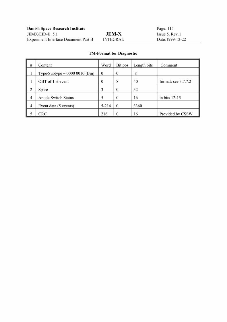
Danish Space Research Institute Page: 115JEMX/EID-B_5.1 JEM-X Issue 5. Rev. 1Experiment Interface Document Part B INTEGRAL Dato:1999-12-22
TM-Format for Diagnostic
# Content Word Bit pos Length bits Comment
1 Type/Subtype = 0000 0010 [Bin] 0 0 8
1 OBT of 1.st event 0 8 40 format: see 3.7.7.2
2 Spare 3 0 32
4 Anode Switch Status 5 0 16 in bits 12-15
4 Event data (5 events) 5-214 0 3360
5 CRC 216 0 16 Provided by CSSW

Danish Space Research Institute Page: 116JEMX/EID-B_5.1 JEM-X Issue 5. Rev. 1Experiment Interface Document Part B INTEGRAL Dato:1999-12-22
3.7.7.11 DPE Memory Dump Format
APID: 110 0000 0110 [Bin] = 1542 (JEM-X unit 1)110 1000 0110 [Bin] = 1670 (JEM-X unit 2)
The detailed format is determined by CSSW.
3.7.7.12 DFEE Memory Dump Format
APID: 110 0000 0110 [Bin] = 1542 (JEM-X unit 1)110 1000 0110 [Bin] = 1670 (JEM-X unit 2)
The detailed format is determined by CSSW.
Memory dumps from the DFEE will be routed via a designated area in the DPE memory.
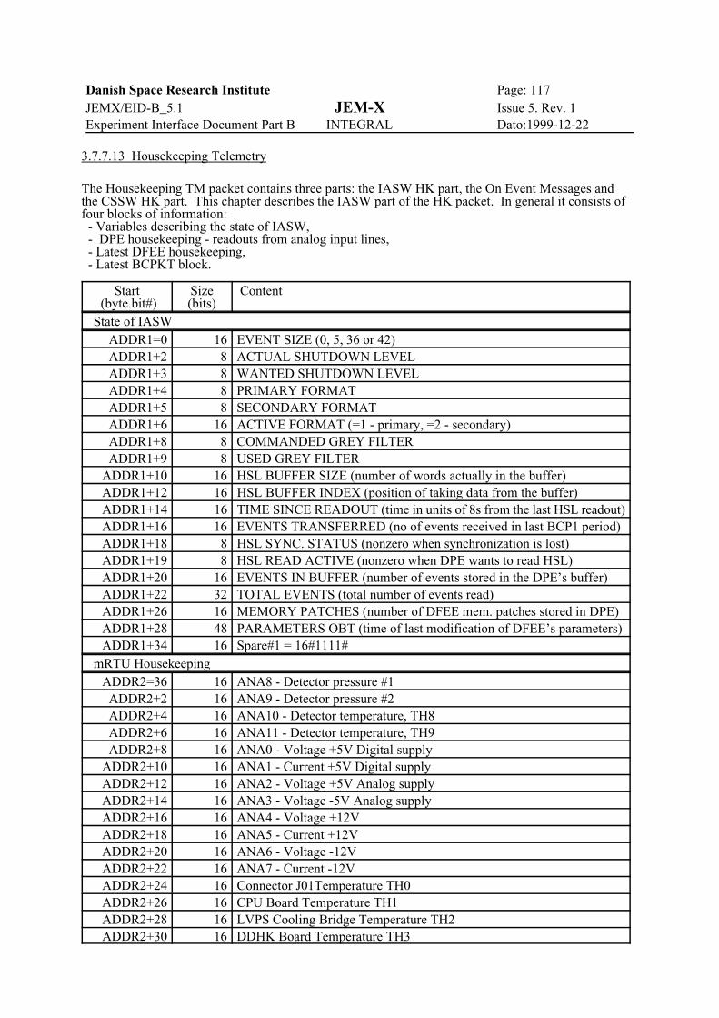
Danish Space Research Institute Page: 117JEMX/EID-B_5.1 JEM-X Issue 5. Rev. 1Experiment Interface Document Part B INTEGRAL Dato:1999-12-22
3.7.7.13 Housekeeping Telemetry
The Housekeeping TM packet contains three parts: the IASW HK part, the On Event Messages andthe CSSW HK part. This chapter describes the IASW part of the HK packet. In general it consists offour blocks of information: - Variables describing the state of IASW, - DPE housekeeping - readouts from analog input lines, - Latest DFEE housekeeping, - Latest BCPKT block.
Start (byte.bit#)
Size(bits)
Content
State of IASWADDR1=0 16 EVENT SIZE (0, 5, 36 or 42)ADDR1+2 8 ACTUAL SHUTDOWN LEVELADDR1+3 8 WANTED SHUTDOWN LEVELADDR1+4 8 PRIMARY FORMATADDR1+5 8 SECONDARY FORMATADDR1+6 16 ACTIVE FORMAT (=1 - primary, =2 - secondary)ADDR1+8 8 COMMANDED GREY FILTERADDR1+9 8 USED GREY FILTER
ADDR1+10 16 HSL BUFFER SIZE (number of words actually in the buffer)ADDR1+12 16 HSL BUFFER INDEX (position of taking data from the buffer)ADDR1+14 16 TIME SINCE READOUT (time in units of 8s from the last HSL readout)ADDR1+16 16 EVENTS TRANSFERRED (no of events received in last BCP1 period)ADDR1+18 8 HSL SYNC. STATUS (nonzero when synchronization is lost)ADDR1+19 8 HSL READ ACTIVE (nonzero when DPE wants to read HSL)ADDR1+20 16 EVENTS IN BUFFER (number of events stored in the DPE’s buffer)ADDR1+22 32 TOTAL EVENTS (total number of events read)ADDR1+26 16 MEMORY PATCHES (number of DFEE mem. patches stored in DPE)ADDR1+28 48 PARAMETERS OBT (time of last modification of DFEE’s parameters)ADDR1+34 16 Spare#1 = 16#1111#
mRTU HousekeepingADDR2=36 16 ANA8 - Detector pressure #1ADDR2+2 16 ANA9 - Detector pressure #2ADDR2+4 16 ANA10 - Detector temperature, TH8 ADDR2+6 16 ANA11 - Detector temperature, TH9ADDR2+8 16 ANA0 - Voltage +5V Digital supply
ADDR2+10 16 ANA1 - Current +5V Digital supplyADDR2+12 16 ANA2 - Voltage +5V Analog supplyADDR2+14 16 ANA3 - Voltage -5V Analog supplyADDR2+16 16 ANA4 - Voltage +12VADDR2+18 16 ANA5 - Current +12VADDR2+20 16 ANA6 - Voltage -12VADDR2+22 16 ANA7 - Current -12VADDR2+24 16 Connector J01Temperature TH0ADDR2+26 16 CPU Board Temperature TH1ADDR2+28 16 LVPS Cooling Bridge Temperature TH2ADDR2+30 16 DDHK Board Temperature TH3

Danish Space Research Institute Page: 118JEMX/EID-B_5.1 JEM-X Issue 5. Rev. 1Experiment Interface Document Part B INTEGRAL Dato:1999-12-22
ADDR2+32 16 Motherboard at ANOD Connector Temperature TH4ADDR2+34 16 Motherboard at ANA2 Board Temperature TH5ADDR2+36 16 ANA12 - FIFO FlagADDR2+38 16 ANA13 - HV Power Supply Temperature, TH7ADDR2+40 16 ANA14 - HV Power Supply Temperature, TH8ADDR2+42 16 ANA15 - SpareADDR2+44 16 Spare#2 = 16#7777#
DFEE HousekeepingADDR3=82 16 HK Cycle CounterADDR3+2 16 DFEE StateADDR3+4 8 Low Level DiscriminatorADDR3+5 8 Anode configurationADDR3+6 16 HV Acc. VoltageADDR3+8 16 HV Drift Voltage
ADDR3+10 4 HV Drift SettingADDR3+10.4 12 HV Acc. Setting
ADDR3+12 16 # of Event TriggersADDR3+14 16 # of Accepted EventsADDR3+16 16 # of Events rejected by grey filterADDR3+18 16 # of Events rejected due to lack of buffer spaceADDR3+20 16 # of Events rejected due to FIFO fullADDR3+22 16 # of Events rejected by upper thresholdADDR3+24 16 # of Events rejected by Veto SignalADDR3+26 16 # of Events rejected by Low RisetimeADDR3+28 16 # of Events rejected by High RisetimeADDR3+30 16 # of Events rejected by Too Many Hits in Back PlaneADDR3+32 16 # of Events rejected by Too Many Hits in Cathode PlaneADDR3+34 16 # of Events rejected by Too High Signal in Back PlaneADDR3+36 16 # of Events rejected by Too Low Signal in Back PlaneADDR3+38 16 # of Events rejected by Too High Signal in Cathode PlaneADDR3+40 16 # of Events rejected by Too Low signal in Cathode PlaneADDR3+42 16 Calibration spectrum partition numberADDR3+44 32 x 16 32 words of calibration spectrum
ADDR3+108 4 x 4 4 bits wrap for #of Event Triggers4 bits wrap for #of Events rejected by grey filter4 bits wrap for #of Events rejected by Too High Signal in Back Plane4 bits wrap for #of Events rejected by Veto Signal
ADDR3+110 16 Hardware Trigger Counter (Also enabled when DFEE is in SETUP state)ADDR3+112 16 Spare#3 = 16#AAAA#
BCPKT PacketADDR4=196 34 x 16 (see [5] for description of Broadcast Packet format)ADDR4+68 16 Spare#4 = 16#FFFF#
State of IASW (continuation)
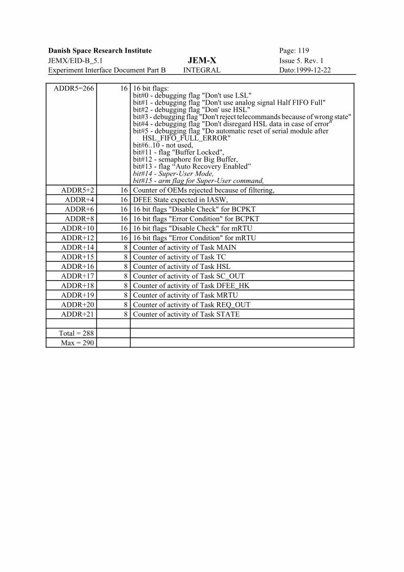
Danish Space Research Institute Page: 119JEMX/EID-B_5.1 JEM-X Issue 5. Rev. 1Experiment Interface Document Part B INTEGRAL Dato:1999-12-22
ADDR5=266 16 16 bit flags:bit#0 - debugging flag "Don't use LSL"bit#1 - debugging flag "Don't use analog signal Half FIFO Full"bit#2 - debugging flag "Don' use HSL"bit#3 - debugging flag "Don't reject telecommands because of wrong state"bit#4 - debugging flag "Don't disregard HSL data in case of error"bit#5 - debugging flag "Do automatic reset of serial module after HSL_FIFO_FULL_ERROR"bit#6..10 - not used,bit#11 - flag "Buffer Locked",bit#12 - semaphore for Big Buffer,bit#13 - flag “Auto Recovery Enabled”bit#14 - Super-User Mode,bit#15 - arm flag for Super-User command,
ADDR5+2 16 Counter of OEMs rejected because of filtering,ADDR+4 16 DFEE State expected in IASW,ADDR+6 16 16 bit flags "Disable Check" for BCPKTADDR+8 16 16 bit flags "Error Condition" for BCPKT
ADDR+10 16 16 bit flags "Disable Check" for mRTUADDR+12 16 16 bit flags "Error Condition" for mRTUADDR+14 8 Counter of activity of Task MAINADDR+15 8 Counter of activity of Task TCADDR+16 8 Counter of activity of Task HSLADDR+17 8 Counter of activity of Task SC_OUTADDR+18 8 Counter of activity of Task DFEE_HKADDR+19 8 Counter of activity of Task MRTUADDR+20 8 Counter of activity of Task REQ_OUTADDR+21 8 Counter of activity of Task STATE
Total = 288Max = 290

Danish Space Research Institute Page: 120JEMX/EID-B_5.1 JEM-X Issue 5. Rev. 1Experiment Interface Document Part B INTEGRAL Dato:1999-12-22
3.7.7.14 On Event Message Telemetry
Each On Event Message occupies 5 words in the Housekeeping TM Packet.
Start(word# . bit#)
Size (bits) Content
0 . 0 32 Time2 . 0 6 Field#12 . 6 2 Class (0-Event, 1-Exception, 2-Major anomaly, 3-Failed TC Report)2 . 8 8 Identifier3 . 0 16 Field#24 . 0 16 Field#3
Identifier specifies a group of messages. For more detailed specification whithin the group Field#1 isused. The two fields - Identifier and Field#1 together forms Message Cathegory. The idea ofcathegory is important because of filtering of OEMs generation. For each of the possible cathegoriesthe time of last issue is stored. Next, if there is a request of generation of the OEM of a givencathegory, coming from inside the IASW part of program, the time is checked and too frequentgeneration is blocked. OEM of a given cathegory can be issued again only 10 seconds after theprevious one. Fields#2 and #3 carry some additional informations, specific to the cathegory of OEM. They are equal to 0 when not used.
Ident. Field#1 Class DescriptionGroup - Telecommand rejected
Field #2 - TC packet header (contains packet counter in bits 3-15)Field #3 - TC packet header:
bits 0-7: spare = 0 bits 8-11: packet type bits 12-15: packet subtype
128 1 Failed TC Report Wrong field TYPE or SUBTYPE129 2 Failed TC Report Wrong field TID or FID130 3 Failed TC Report Wrong field MID131 4 Failed TC Report Wrong field ADDRESS132 5 Failed TC Report Wrong field LENGTH or wrong length of the TC itself133 6 Failed TC Report Some other errors in the text of TC134 7 Failed TC Report DPE is busy - TC input queue is full135 8 Failed TC Report HW Command illegal because of shutdown in progress136 9 Failed TC Report State change illegal because of shutdown in progress137 10 Failed TC Report Execution started but failed138 31 Failed TC Report Wrong command „Set Super-user priv.” (fire without arm)
(Fields #2 and #3 are not used)Group - Problems with HSL
151 1 Major anomaly Overflow158 8 Major anomaly CRC error159 9 Major anomaly Timeout154 11 Event Loss of synchronization
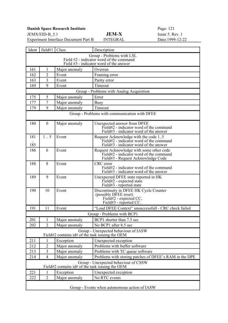
Danish Space Research Institute Page: 121JEMX/EID-B_5.1 JEM-X Issue 5. Rev. 1Experiment Interface Document Part B INTEGRAL Dato:1999-12-22
Ident field#1 Class DescriptionGroup - Problems with LSL
Field #2 - indicator word of the command Field #3 - indicator word of the answer161 1 Major anomaly Overrun162 2 Event Framing error163 3 Event Parity error169 9 Event Timeout
Group - Problems with Analog Acquisition175 5 Major anomaly Error177 7 Major anomaly Busy179 9 Major anomaly Timeout
Group - Problems with communication with DFEE
180 0 Major anomaly Unexpected answer from DFEE Field#2 - indicator word of the command Field#3 - indicator word of the answer
181..
185
1 .. 5 Event Request Acknowledge with the code 1..5 Field#2 - indicator word of the command Field#3 - indicator word of the answer
186 6 Event Request Acknowledge with some other code Field#2 - indicator word of the command Field#3 - Request Acknowledge Code
188 8 Event CRC error Field#2 - indicator word of the command Field#3 - indicator word of the answer
189 9 Event Unexpected DFEE state reported in HK Field#2 - expected state Field#3 - reported state
190 10 Event Discontinuity in DFEE HK Cycle Counter (possibly DFEE reset) Field#2 - expected CC, Field#3 - reported CC.
191 11 Event “Load DFEE Context” unsuccessfull - CRC check failedGroup - Problems with BCP1
201 1 Major anomaly BCP1 shorter than 7.5 sec202 2 Major anomaly No BCP1 after 8.5 sec
Group - Unexpected behaviour of IASW Field#2 contains id# of the task issuing the OEM211 1 Exception Unexpected exception212 2 Major anomaly Problems with buffer software213 3 Major anomaly Problems with TC queue software214 4 Major anomaly Problems with storing patches of DFEE’s RAM in the DPE
Group - Unexpected behaviour of CSSW Field#2 contains id# of the task issuing the OEM221 1 Exception Unexpected exception222 2 Major anomaly No RTC events
Group - Events when autonomous action of IASW
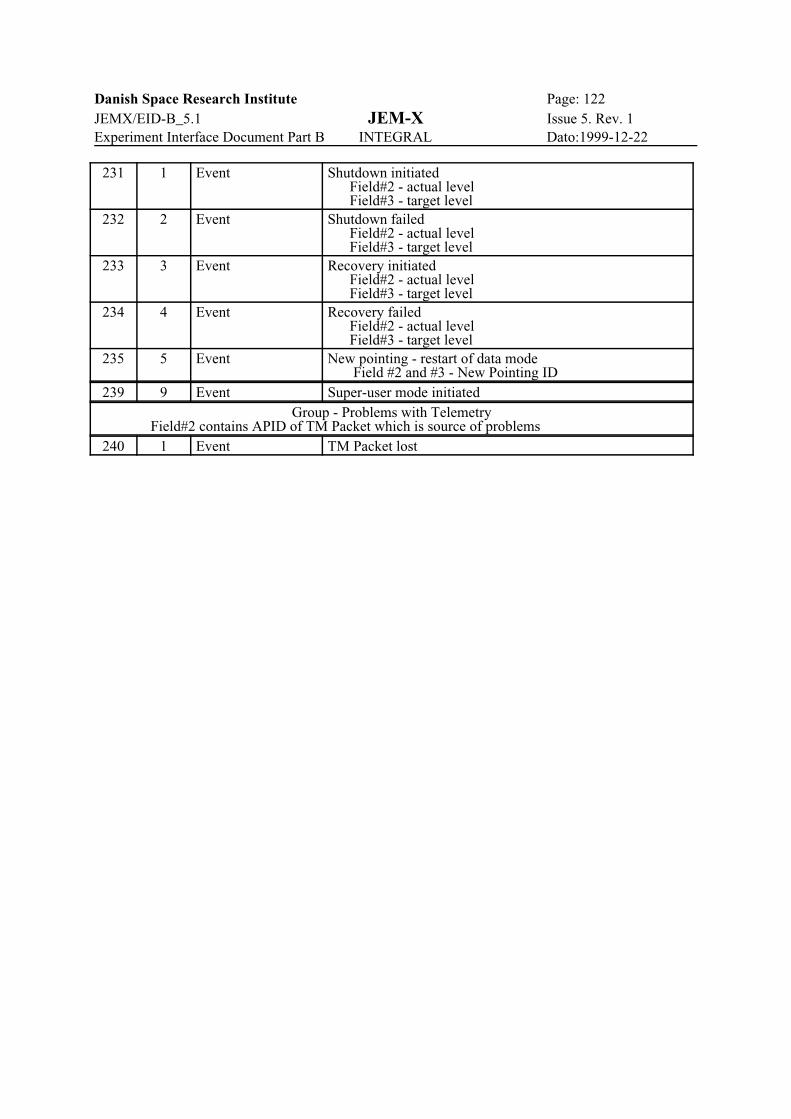
Danish Space Research Institute Page: 122JEMX/EID-B_5.1 JEM-X Issue 5. Rev. 1Experiment Interface Document Part B INTEGRAL Dato:1999-12-22
231 1 Event Shutdown initiated Field#2 - actual level Field#3 - target level
232 2 Event Shutdown failed Field#2 - actual level Field#3 - target level
233 3 Event Recovery initiated Field#2 - actual level Field#3 - target level
234 4 Event Recovery failed Field#2 - actual level Field#3 - target level
235 5 Event New pointing - restart of data mode Field #2 and #3 - New Pointing ID
239 9 Event Super-user mode initiatedGroup - Problems with Telemetry
Field#2 contains APID of TM Packet which is source of problems240 1 Event TM Packet lost

Danish Space Research Institute Page: 123JEMX/EID-B_5.1 JEM-X Issue 5. Rev. 1Experiment Interface Document Part B INTEGRAL Dato:1999-12-22
3.7.7.15 Software Diagnostic Telemetry
SW Diagnostic is generated on request in form of TM(5,4)/TID=1/FID=16. It can also be producedperiodically in the same form.
This TM packet contains set of counters of events, which are interesting for diagnostic ot the software. Each issue of this report clears the counters, so each report shows counts made between reports.
Start (word#) Events countedGroup - TC
0 Constant 16#1111#1 Received TC2 Corrupted TC3 Rejected TC4 Timeout when reading TC5 Timeout of BCP16 BCP1 too short7 No RTC
Group - ADC8 Constant 16#2222#9 ADC readout
10 ADC error11 ADC busy12 ADC timeout
Group - LSL13 Constant 16#3333#14 Command sent15 LSL error16 CRC eror17 LSL timeout18 Aborted communication request
Group - HSL19 Constant 16#4444#20 HSL readout21 CRC error22 HSL timeout23 HSL overflow24 HSL lost synchronization25 Constant 16#5555#
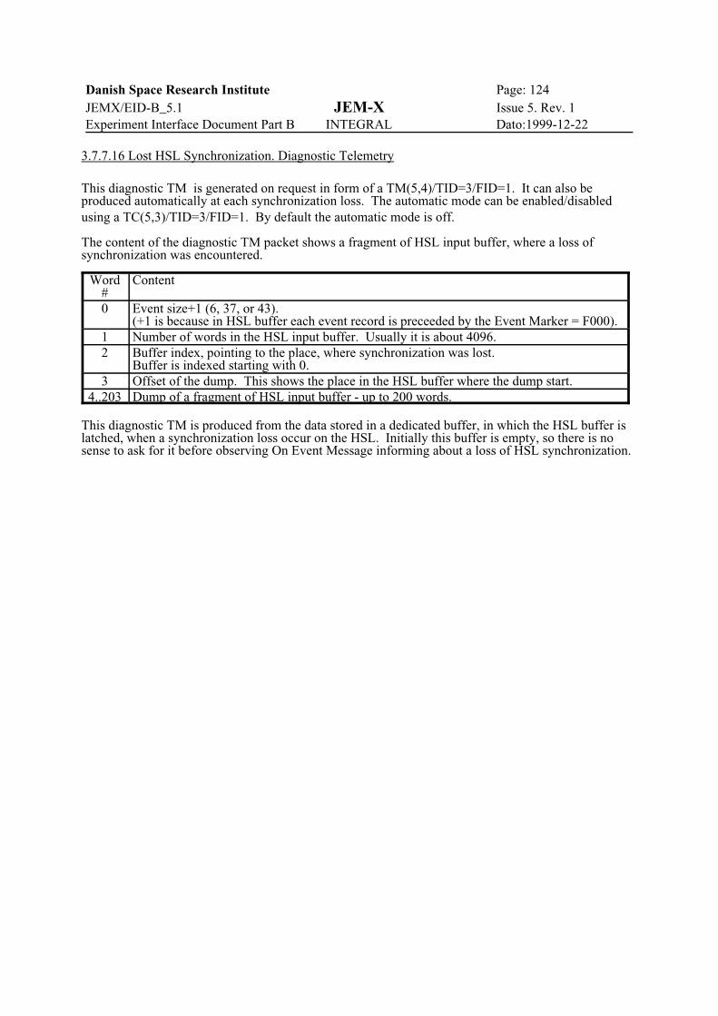
Danish Space Research Institute Page: 124JEMX/EID-B_5.1 JEM-X Issue 5. Rev. 1Experiment Interface Document Part B INTEGRAL Dato:1999-12-22
3.7.7.16 Lost HSL Synchronization. Diagnostic Telemetry
This diagnostic TM is generated on request in form of a TM(5,4)/TID=3/FID=1. It can also beproduced automatically at each synchronization loss. The automatic mode can be enabled/disabledusing a TC(5,3)/TID=3/FID=1. By default the automatic mode is off.
The content of the diagnostic TM packet shows a fragment of HSL input buffer, where a loss ofsynchronization was encountered.
Word#
Content
0 Event size+1 (6, 37, or 43). (+1 is because in HSL buffer each event record is preceeded by the Event Marker = F000).
1 Number of words in the HSL input buffer. Usually it is about 4096.2 Buffer index, pointing to the place, where synchronization was lost.
Buffer is indexed starting with 0.3 Offset of the dump. This shows the place in the HSL buffer where the dump start.
4..203 Dump of a fragment of HSL input buffer - up to 200 words.
This diagnostic TM is produced from the data stored in a dedicated buffer, in which the HSL buffer islatched, when a synchronization loss occur on the HSL. Initially this buffer is empty, so there is nosense to ask for it before observing On Event Message informing about a loss of HSL synchronization.

Danish Space Research Institute Page: 125JEMX/EID-B_5.1 JEM-X Issue 5. Rev. 1Experiment Interface Document Part B INTEGRAL Dato:1999-12-22
3.7.8 TM parameter description
Refer to the SDB.
3.7.9 CPU and memory budget
DPE CPU MA31750A
Usage: 65% of 80 kword ROM20 % of 2 Mword RAM
DFEE CPU MA31750A
Usage: 60% of 8 kword ROM75 % of 32 kword RAM
3.7.10 JEM-X Autonomous Functions
3.7.10.1 Hardware Autonomous Functions
3.7.10.1.1 DFEE Undervoltage Protection
A protection circuit will inhibit the DFEE Low Voltage Converters from starting up until the inputvoltage exceeds 22 V. The same circuit will also switch off the power converters if the input voltagesinks below 18.5 V after the power converters have been started up. This circuit is incorporated toprevent excessive currents to be drawn through the supply line filters.
The undervoltage protection mechanism cannot be inhibited.
3.7.10.1.2 JEM-X High Voltage Switch-Off by Internal Ratemeter
A hard wired ratemeter will switch off the high voltage to the JEM-X detector if the trigger countsexceeds 65535 over an 8 second period.
The ratemeter sensitivity is adjustable through the setting of the discriminator providing the input forthe ratemeter (and the event trigger signal for instrument). This ratemeter will function even if theDFEE is in the SETUP state, since it is the raw trigger signals which are counted, not the processedtriggers.
The disappearence of the high voltage will be detected by the DFEE software, which will report theHV-status to the DPE at the next transfer of the DFEE housekeeping data. The DPE IASW will thenset the DFEE to the SAFE state.
Autonomous recovery will not be invoked following a internal ratemeter induced switch off.
The hardware switch-off mechanism can be inhibited.
3.7.10.2 Software Autonomous Functions
3.7.10.2.1 JEM-X High Voltage Switch-Off by Software Ratemeter
A software ratemeter will switch off the high voltage to the JEM-X detector if the processed triggercounts exceeds a predefined limit (default value 32767) over an 8 second period. Note that thisratemeter is only active when the DFEE is in the Normal Data Taking mode.
The ratemeter sensitivity is adjustable through the choice of the limiting count and the setting of thediscriminator providing the input for the instrument event trigger. The Grey Filter value does notaffect the software ratemeter sensitivity.
The DFEE software will report the high count condition to the DPE at the next transfer of the DFEE

Danish Space Research Institute Page: 126JEMX/EID-B_5.1 JEM-X Issue 5. Rev. 1Experiment Interface Document Part B INTEGRAL Dato:1999-12-22
housekeeping data. The DPE IASW will then set the DFEE to the SAFE state.
Autonomous recovery may be invoked following a software ratemeter induced switch off.
The software switch-off mechanism can be inhibited.
3.7.10.2.2 Autonomous Transition to DFEE SAFE state (shut-down) according to Broadcast Packet
The DPE IASW will set the DFEE to the SAFE state when the Broadcast Packet indicates this to benecessary, such as at Radiation Belt Entry, Eclipse Entry, Radiation Monitor count rates out of range or Satellite Emergencies (ESAM, Instrument Switch-off Imminent).
A copy of the parameter values used by the DFEE is always kept in the DPE memory, to assure a fullrecovery of the current DFEE state following a power switch-off.
DFEE Autonomous recovery may be invoked following a Broadcast Packet induced transition toSAFE.
3.7.10.2.3 Autonomous Recovery from a shut-down.
The DPE IASW may restore the working state of the DFEE to a previously existing state when thecondition causing the shut-down has disappeared. This includes the restoration of the detector highvoltage values to their previous values. During this recovery any updates to the DFEE software whichare available in the DPE will be implemented before setting the high voltage and, possibly, the transferto the Normal Data Taking mode.
3.7.10.2.4 Change of format for the Science Telemetry
The JEM-X science telemetry will be allowed to switch between two different telemetry formatsaccording to the instantaneous count rate - actually, according to the degree of filling of the LargeData Buffer in the DPE.
3.7.10.2.5 Grey Filter adjustment
The event rate which can be transmitted through the JEM-X telemetry allocation is very limited, andwe will frequently encounter situations where more events are recorded than can be tranmitted. Wewill then try to adjust an unbiased filtering mechanism (the Grey Filter) so as to achieve a stablesituation with the Large Data Buffer in the DPE about half full.
3.7.10.2.6 Autonomous termination of DFEE CALIBRATION mode.
The CALIBRATION mode of the DFEE is self terminating, after a defined number of events theDFEE will revert to the SETUP mode.
3.7.10.2.7 Autonomous termination of DFEE DIAGNOSTIC mode.
The DIAGNOSTIC mode of the DFEE is self terminating, after a defined number of events the DFEEwill revert to the SETUP mode.
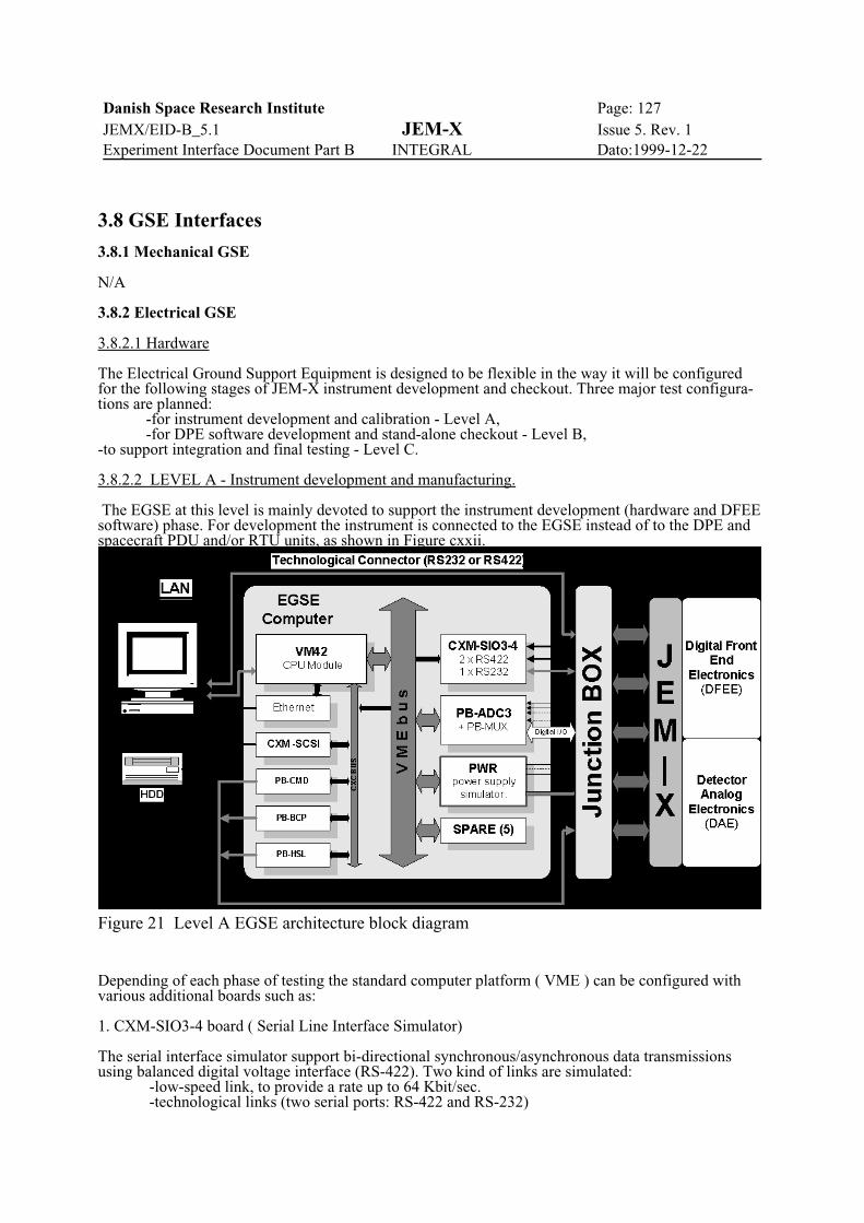
Danish Space Research Institute Page: 127JEMX/EID-B_5.1 JEM-X Issue 5. Rev. 1Experiment Interface Document Part B INTEGRAL Dato:1999-12-22
Figure 21 Level A EGSE architecture block diagram
3.8 GSE Interfaces
3.8.1 Mechanical GSE
N/A
3.8.2 Electrical GSE
3.8.2.1 Hardware
The Electrical Ground Support Equipment is designed to be flexible in the way it will be configuredfor the following stages of JEM-X instrument development and checkout. Three major test configura-tions are planned: -for instrument development and calibration - Level A, -for DPE software development and stand-alone checkout - Level B, -to support integration and final testing - Level C.
3.8.2.2 LEVEL A - Instrument development and manufacturing.
The EGSE at this level is mainly devoted to support the instrument development (hardware and DFEEsoftware) phase. For development the instrument is connected to the EGSE instead of to the DPE andspacecraft PDU and/or RTU units, as shown in Figure cxxii.
Depending of each phase of testing the standard computer platform ( VME ) can be configured withvarious additional boards such as:
1. CXM-SIO3-4 board ( Serial Line Interface Simulator)
The serial interface simulator support bi-directional synchronous/asynchronous data transmissionsusing balanced digital voltage interface (RS-422). Two kind of links are simulated:
-low-speed link, to provide a rate up to 64 Kbit/sec.-technological links (two serial ports: RS-422 and RS-232)

Danish Space Research Institute Page: 128JEMX/EID-B_5.1 JEM-X Issue 5. Rev. 1Experiment Interface Document Part B INTEGRAL Dato:1999-12-22
2. PB-HSL board (High-Speed Link simulator)
The uni-directional synchronous serial interface simulator receives data from the instrument at a rateof up to 5 Mbit/sec transmission rate using balanced digital voltage interface (RS-422).
3. PB-ADC3 and PB-MUX boards ( Analogue & Thermistor HK channels)These boards are providingHousekeeping data acquisition and monitoring functions. Both, the DPU and the RTU acquisition linesare simulated.- 16 analogue inputs ( res. 12 bit ),- 16 Thermistor YSI 44908 channels.
4. PB-CMD board (Discrete command lines)
The TC pulse generation controller and associated electrical interface for generation of High PowerTelecommand On/Off pulses. The four separate lines are simulated. To facilitate verification ofinstrument interfaces it is possible to set an amplitude and pulse period to its maximum, normal andminimum values. Specifications:Number of lines: 4Pulse Amplitude: 12 - 16 [V]Pulse Width: 10 - 20 [ms]Imax 300 [mA]
5. PB-BCP (DPE Timing Lines simulator).
The timing line simulator consists of four lines as this ones issued from DPE. Timing interfaceprovides:INST_CLK 4.19 MHz clockBCP1 8 Hz timing pulsesBCP2 1 Hz timing pulsesCLK8N 1/8 Hz timing pulses
6. PWR module ( Power supply simulator).
This module is responsible for the provision of all power to the instrument or heater as would beprovided by flight PDU. For his purpose PWR module consists of a programmable controlled DC/DCconverter with current limiting and over-voltage protection. The PWR module is equipped with abuilt-in self test procedure. Features of the PWR module:Output power : 40 W (max.). Output voltage: 24 - 32 V ( nom. 28V) Load current: 1.2 A (max.)Output current and voltage monitoring (resolution 8bit) Spare hardware slots are available to allow extra instrument interfaces and system modules to beincorporated without design impact. Each interface simulator includes its own servicing task to allowfor flexible configuration and fast software upgrade.
3.8.2.3 LEVEL B - Instrument integration, calibration and testing.
This level is required to verify the complete instrument parameters fields, including the worst testconditions and final calibrations. Additionally, the EGSE in this configuration will be used for DPE software development anddebugging. The INTEGRAL SIS" is also planned to be used at this level. Figure cxxiv shows the EGSEarchitecture
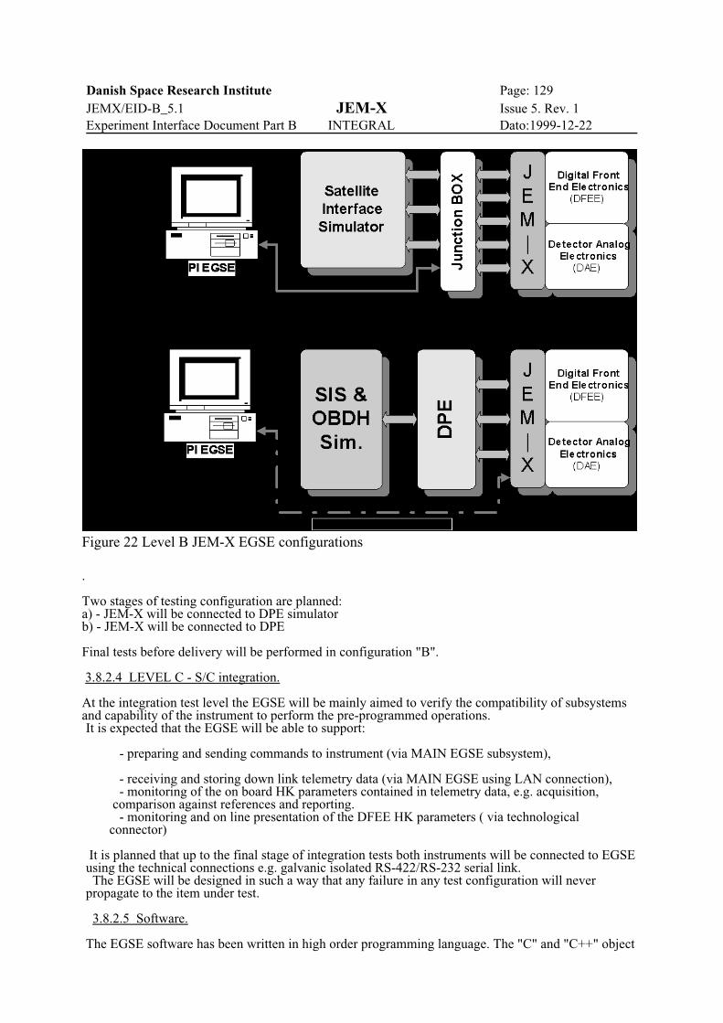
Danish Space Research Institute Page: 129JEMX/EID-B_5.1 JEM-X Issue 5. Rev. 1Experiment Interface Document Part B INTEGRAL Dato:1999-12-22
Figure 22 Level B JEM-X EGSE configurations
.
Two stages of testing configuration are planned:a) - JEM-X will be connected to DPE simulator b) - JEM-X will be connected to DPE
Final tests before delivery will be performed in configuration "B".
3.8.2.4 LEVEL C - S/C integration.
At the integration test level the EGSE will be mainly aimed to verify the compatibility of subsystemsand capability of the instrument to perform the pre-programmed operations.It is expected that the EGSE will be able to support:
- preparing and sending commands to instrument (via MAIN EGSE subsystem),
- receiving and storing down link telemetry data (via MAIN EGSE using LAN connection), - monitoring of the on board HK parameters contained in telemetry data, e.g. acquisition, comparison against references and reporting. - monitoring and on line presentation of the DFEE HK parameters ( via technological connector)
It is planned that up to the final stage of integration tests both instruments will be connected to EGSEusing the technical connections e.g. galvanic isolated RS-422/RS-232 serial link. The EGSE will be designed in such a way that any failure in any test configuration will neverpropagate to the item under test.
3.8.2.5 Software.
The EGSE software has been written in high order programming language. The "C" and "C++" object

Danish Space Research Institute Page: 130JEMX/EID-B_5.1 JEM-X Issue 5. Rev. 1Experiment Interface Document Part B INTEGRAL Dato:1999-12-22
Figure 23 EGSE software structure (OS/9 part)
oriented language has been used. However, some part of software, like drivers, handlers, act. waswritten in assembler language.The programs used in various EGSE configurations consists of twomain parts:
1. "OS/9 part" running on powerful VME-bus computer PEP-VM42 (Motorola 68040 CPU + 68360). 2. "Windows part" running on PENTIUM CPU based PC. The "OS/9 Part" perform all necessary real time processing relevant to the I/O boards (interfacesimulators). An application software is built by a number of concurrent tasks in charge of performingthe following functions:
1. I/O VME modules set-up - perform the set-up of the I/O simulators modules according tothe command sent by operator's test sequence. 2. Real-time processing - perform all necessary real time processing relevant to I/O modules
data acquisition (HK channels scanning), data time-stamping, interface health monitoring, correlationof acquired data to dedicated responses (alarm events triggering), data blocks collecting andpre-formatting. 3. Host Computer(s) interfacing - perform the interface with the Host Computer(s) via serialdirect connection and/ or LAN interface according to TCP/IP protocol logical link. Communicationprocess in order to acquire set-up commands, transmits to the host data, simulator status and errormessages.Figure cxxv shows the software logical structure of this part and its relations with hardware . The "Windows part" is based on a common Basic Software Platform (DOS / Windows / WindowsNT) and provides the following main task: 1. Graphical User Interface All operation performed by user (operator) can be done like in theother regular "Windows" applications. All test results are displayed with techniques optimised forhuman perception (e.g., tables, colour graphic pictures, histograms, diagrams, bar graph, act.) 2. Tests preparation end execution. The specialised script language has been written. Thebuilt-in interpreter allows the operator to run prepared test sequence. 3. Data Monitoring and Displaying. A dedicated HK Channels Database set-up facilityallowing the operator to easily describe the data channel sets that will be monitored. When test resultsexceeds predefined values an event alarm is displayed. (numerical and graphical presentation) 4. Data archiving (calibration and test data ), The data received from tested instrument can be

Danish Space Research Institute Page: 131JEMX/EID-B_5.1 JEM-X Issue 5. Rev. 1Experiment Interface Document Part B INTEGRAL Dato:1999-12-22
Figure 24 EGSE software structure (IBM/PC - "Windows" part)
stored at run-time. 5. Test results presentation and report generation. It will be possible to produce all test relateddocuments on the system, directly accessing or including data and graphics produced during the testprocess. (Instrument Data and EGSE Event log Database). 6. Data Base Management, 7. Instrument Development Support, (technical connection) 8. "OS/9 platform" Communication, 9. EGSE self-test and diagnostic, The basic checkout kernel for each testing level will carryout subsystem or module main test (answer: GOOD or FILED). Only in case of detection of errors (oroperator request) detailed testing or calibration procedures (and/or child processes) will be performed.
The software will be structured such that it could be adapted to several testing levels. Functionswhich needs flexible adaptation during the test will be changeable without S/W recompilation. Thegeneral view of this part of EGSE software structure is shown on Figure cxxvi

Danish Space Research Institute Page: 132JEMX/EID-B_5.1 JEM-X Issue 5. Rev. 1Experiment Interface Document Part B INTEGRAL Dato:1999-12-22
3.9 ISSW - Instrument specific software
The ISSW is the software to handle the instrument specific parts of the data. The software shall beinstalled at the ISDC, following the ISDC requirements. The software development will followPSS-05.
The software is briefly described in the following. It is described in more detail in the separatedocuments for the User Requirements (ISDC-URD), the Logical Model (ISDC-LMD) and theArchitectural Design Document (ADD). The software will be documented according to PSS-05.
Parts of the following developments will be done by the ISDC.
3.9.1 Instrument health monitoring
The health monitoring software will examine the House Keeping HK data stream. The process will beautomatic, and will be able to alert the operator in case of faults detected. The process will run at theMission Operation Centre (MOC) and the software will be developed by the MOC according tospecifications provided by the Instrument Team. The issues will at least be: - conversion of HK parameters to physical units - examination of HK parameters for excess of threshold settings. - possibility to display HK parameters through interactive control, or automatic, if an alert (outside threshold) has arisen. - produce alert to operator if alert flag is set. - examination of status of execution of telecommands.
3.9.2 Instrument performance monitoring
The performance monitoring software will provide a deeper analysis of the telemetry stream for thepurpose of monitoring the scientific and technical performance of the instrument. It will use both theHouse Keeping data stream, event data from the calibration sources included in the science telemetry,and it will use data from previous observations. This combination will give a more completedescription of the instrument performance than the health monitoring and will allow looking fortransients on different timescales.
Events from the on-board calibration sources will be used for a continuous calculation of gain andresponse, by collecting the spectra from each calibration source in the HK data strem.
The process will be automatic, and will be able to alert the operator in case of alarming trends. Theissues will at least be: - conversion of HK parameters to physical units - examination of HK parameters for excess of threshold settings. - examination of gain and response obtained from a continuous calibration (see Preprocessing) - examination of internal calibration source, gain monitoring - examination of changes in performance parameters compared to previous observations - possibility to display of HK and calibration parameters through interactive control, or automatic, if an alert (outside threshold) has arisen. - produce alert to operator if alert flag is set. - store performance parameters as part of instrument history. - determination of internal calibration source spectra, gain history
3.9.3 Preprocessing software
The JEM-X preprocessing software (removal of instrument signatures) will at least cover thefollowing issues: - bad event examination - position linearization - gain variation correction - energy channel linearization - energy calibration

Danish Space Research Institute Page: 133JEMX/EID-B_5.1 JEM-X Issue 5. Rev. 1Experiment Interface Document Part B INTEGRAL Dato:1999-12-22
- detector efficiency correctionFurther, the pre-processing software shall estimate the background - output in FITS events format (OGIP "standard", eg. RDF format).
3.9.4 Quick Look analysis
The QL software will run on all of the JEM-X data to monitor that the scientific goals of theobservation is met, and to check that that the objects at which the observation was aimed are actuallyin the field of view. It will also allow observers to detect interesting astronomical events in the fieldof view. The software will probably resemble the Standard Analysis software, but will use simpleralgorithms when possible and fewer bins in histograms to provide faster display of results. It isexpected, that the ISDC provides tools for displaying the images. The software will at least cover thefollowing issues: - quick image reconstruction - image storing in FITS files using available auxiliary information. - background determination. - quick source position determination. - quick timing analysis - quick spectral analysis - comparison with simulation if applicableSome of these issues are not relevant for all instrumental modes.
3.9.5 Standard analysis software
The Standard Analysis software will run on all of the JEM-X software and will produce a set ofstandard data products to be delivered to the observer with the raw data. The software will containmany of the elements of the Quick Look analysis, but possibly use a higher number of bins and theoptimal algorithms when applicable: - image reconstruction with refined image reconstruction in areas of interest - image storing in FITS files using auxiliary information. - background determination. - background modeling - source position determination - source identification using sky catalogues - timing analysis - spectral analysis and spectral modeling of sources in field of viewSome of these issues are not relevant for all instrumental modes.
The timing and spectral analysis is only possible to the extend where images are still possible toconstruct. The requirements are at least several hundred counts/s for the source in question. In casethe source is dominating all other point sources, the system can be analysed as a usual collimateddetector.
Having produces lightcurves, spectra or images, it is assumed that already existing software packageswill be used for detailed analysis.
3.9.6 Simulation software
The JEM-X simulation software package is available in a preliminary form. The package will containthe following: estimating software
- estimates of count-rates, using eg. PIMMS similar software detailed simulation- Monte-Carlo ray-tracing- storage of simulated shadowgrams in FITS files (event files).- Production of files to simulation runs of software, both ISDC relevant software and
ESOC simulator software (see 3.9.7).
3.9.7 Simulation files
The JEM-X team will produce the sets of files specified in general terms in EID-A section 7.5.3.3.The set will be split in files according to mode.

Danish Space Research Institute Page: 134JEMX/EID-B_5.1 JEM-X Issue 5. Rev. 1Experiment Interface Document Part B INTEGRAL Dato:1999-12-22

Danish Space Research Institute Page: 135JEMX/EID-B_5.1 JEM-X Issue 5. Rev. 1Experiment Interface Document Part B INTEGRAL Dato:1999-12-22
APPENDIX A
Mechanical Interface Control Document (MICD) according DRD-42-1.
The drawings can also be downloaded in PDF format from the DSRI JEMX FTP server as:
j-det-i.pdf JEM-X #130010 rev. B (Detector/DFEE assembly)
J-mask-i.pdf IN-JX-SR-DW-100-00 (Coded mask assembly)
Please note, that the drawings found in this appendix are not to scale.
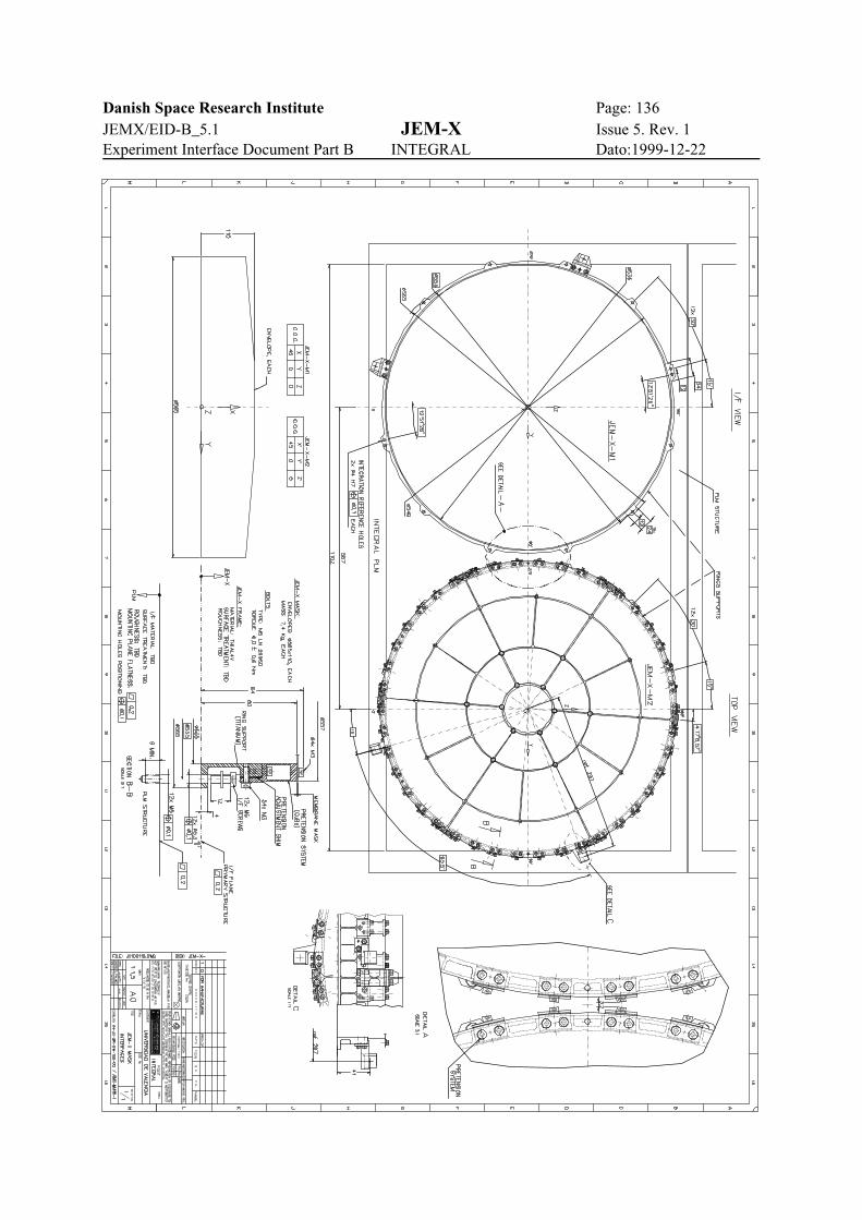
Danish Space Research Institute Page: 136JEMX/EID-B_5.1 JEM-X Issue 5. Rev. 1Experiment Interface Document Part B INTEGRAL Dato:1999-12-22
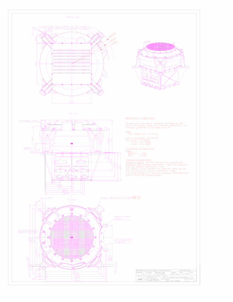
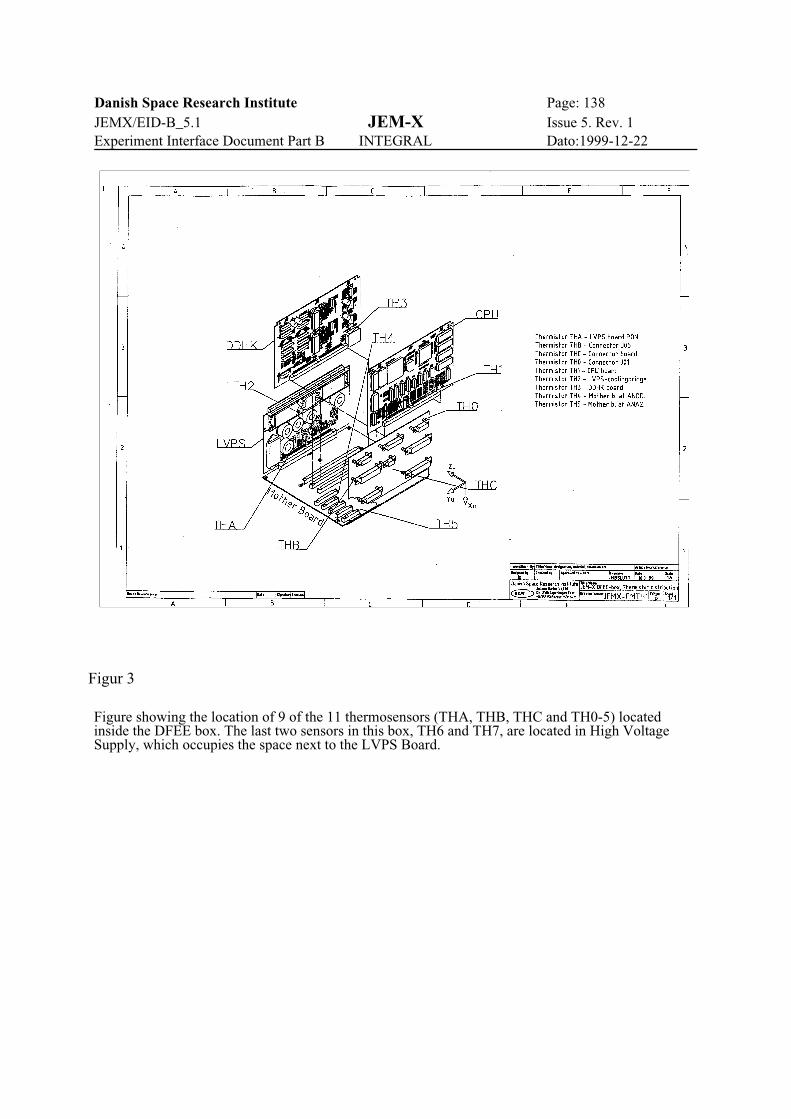
Danish Space Research Institute Page: 138JEMX/EID-B_5.1 JEM-X Issue 5. Rev. 1Experiment Interface Document Part B INTEGRAL Dato:1999-12-22
Figur 3
Figure showing the location of 9 of the 11 thermosensors (THA, THB, THC and TH0-5) locatedinside the DFEE box. The last two sensors in this box, TH6 and TH7, are located in High VoltageSupply, which occupies the space next to the LVPS Board.
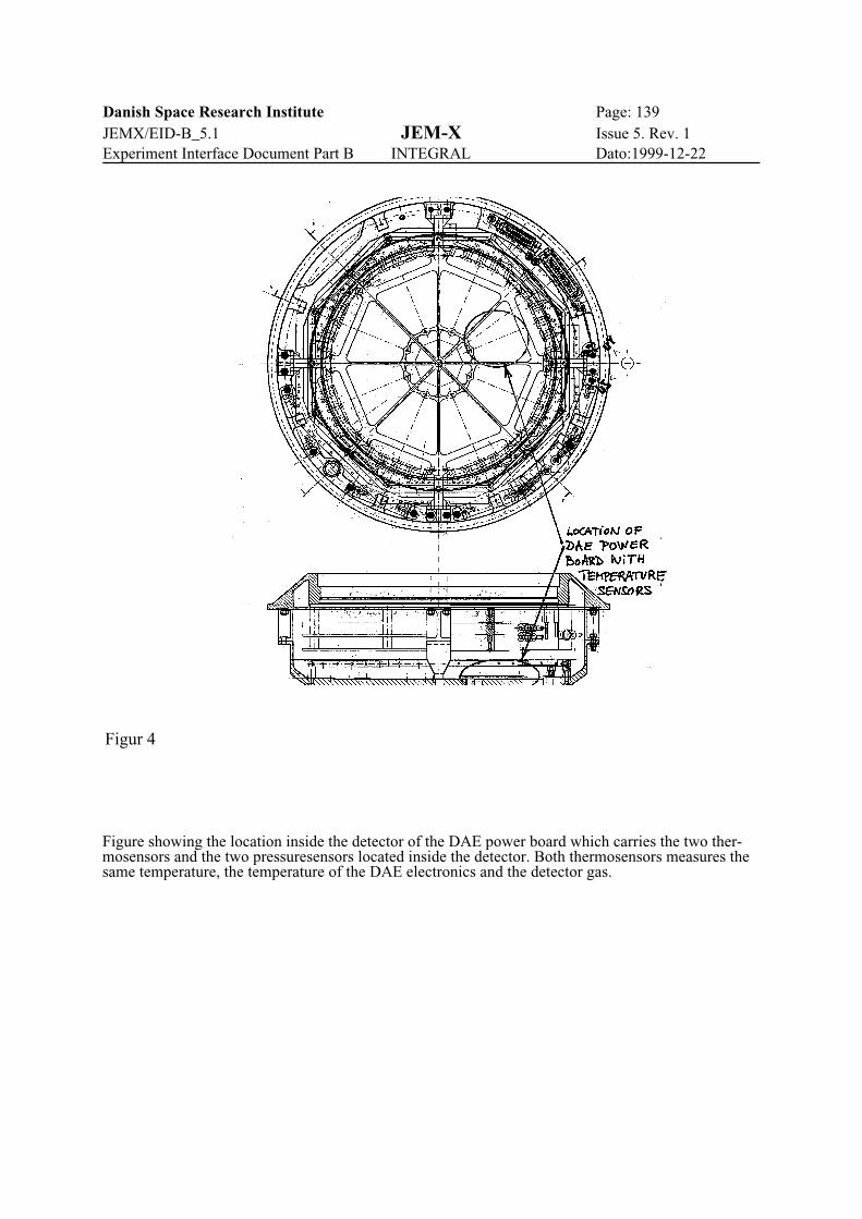
Danish Space Research Institute Page: 139JEMX/EID-B_5.1 JEM-X Issue 5. Rev. 1Experiment Interface Document Part B INTEGRAL Dato:1999-12-22
Figur 4
Figure showing the location inside the detector of the DAE power board which carries the two ther-mosensors and the two pressuresensors located inside the detector. Both thermosensors measures thesame temperature, the temperature of the DAE electronics and the detector gas.
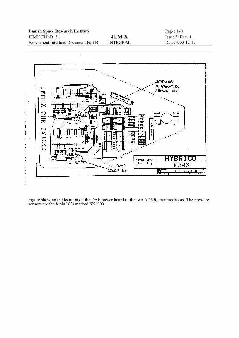
Danish Space Research Institute Page: 140JEMX/EID-B_5.1 JEM-X Issue 5. Rev. 1Experiment Interface Document Part B INTEGRAL Dato:1999-12-22
Figure showing the location on the DAE power board of the two AD590 thermosensors. The pressuresensors are the 8-pin IC’s marked SX1000.

Danish Space Research Institute Page: 141JEMX/EID-B_5.1 JEM-X Issue 5. Rev. 1Experiment Interface Document Part B INTEGRAL Dato:1999-12-22
APPENDIX B
Electrical Interface Control Document (EICD) according to DRD44-1.
Introduction
SSSS Purpose
The purpose of this document is to establish the Electrical I/F characteristics of JEM-X.
JEM-X consists of:
The Detector Unit (DAE) and the Electronics Unit (DFEE). The two units are delivered integrated asone unit (JEM-X). JEM-X has two different electrical interfaces:
- External from the DFEE to the S/C via the DPE, RTU and PDU- Internal between the DFEE and the DAE.
List of Acronyms
DAE Detector Analog ElectronicsDFEE Digital Front End ElectronicsDPE Data Processing ElectronicsEGSE Electrical Ground Support EquipmentEICD Electrical Interface Control DocumentEID Experiment Interface DocumentESA European Space AgencyHS High SpeedI/F InterfaceJEM-X Joint European X-Ray MonitorLS Low SpeedPDU Power distribution UnitRTU Remote Terminal UnitS/C Spacecraft
SSSS Applicable Documents
Experiment Interface Document (EID) - Part A
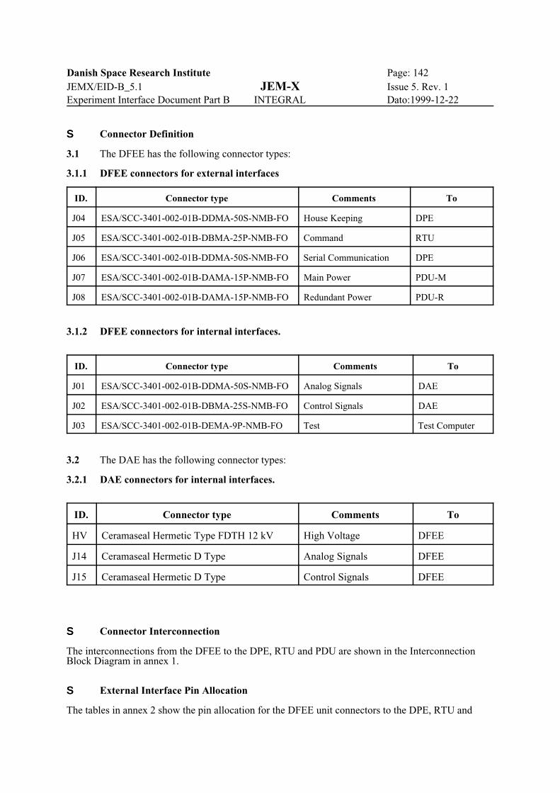
Danish Space Research Institute Page: 142JEMX/EID-B_5.1 JEM-X Issue 5. Rev. 1Experiment Interface Document Part B INTEGRAL Dato:1999-12-22
SSSS Connector Definition
3.1 The DFEE has the following connector types:
3.1.1 DFEE connectors for external interfaces
ID. Connector type Comments To
J04 ESA/SCC-3401-002-01B-DDMA-50S-NMB-FO House Keeping DPE
J05 ESA/SCC-3401-002-01B-DBMA-25P-NMB-FO Command RTU
J06 ESA/SCC-3401-002-01B-DDMA-50S-NMB-FO Serial Communication DPE
J07 ESA/SCC-3401-002-01B-DAMA-15P-NMB-FO Main Power PDU-M
J08 ESA/SCC-3401-002-01B-DAMA-15P-NMB-FO Redundant Power PDU-R
3.1.2 DFEE connectors for internal interfaces.
ID. Connector type Comments To
J01 ESA/SCC-3401-002-01B-DDMA-50S-NMB-FO Analog Signals DAE
J02 ESA/SCC-3401-002-01B-DBMA-25S-NMB-FO Control Signals DAE
J03 ESA/SCC-3401-002-01B-DEMA-9P-NMB-FO Test Test Computer
3.2 The DAE has the following connector types:
3.2.1 DAE connectors for internal interfaces.
ID. Connector type Comments To
HV Ceramaseal Hermetic Type FDTH 12 kV High Voltage DFEE
J14 Ceramaseal Hermetic D Type Analog Signals DFEE
J15 Ceramaseal Hermetic D Type Control Signals DFEE
SSSS Connector Interconnection
The interconnections from the DFEE to the DPE, RTU and PDU are shown in the InterconnectionBlock Diagram in annex 1.
SSSS External Interface Pin Allocation
The tables in annex 2 show the pin allocation for the DFEE unit connectors to the DPE, RTU and

Danish Space Research Institute Page: 143JEMX/EID-B_5.1 JEM-X Issue 5. Rev. 1Experiment Interface Document Part B INTEGRAL Dato:1999-12-22
PDU.
SSSS Internal Interface Pin Allocation.
The tables in annex 3 show the pin allocation between the DFEE unit connectors and the DAE.
SSSS Interface Circuits.
The Interface Circuits are shown in Annex 4
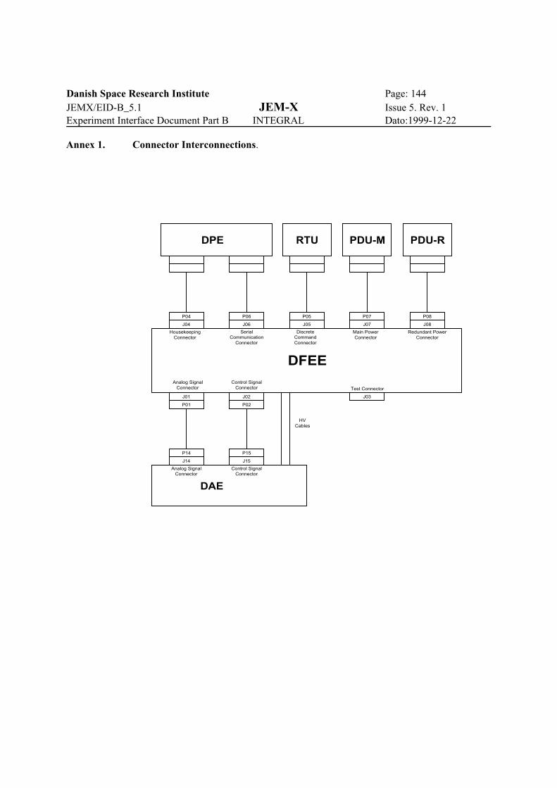
Danish Space Research Institute Page: 144JEMX/EID-B_5.1 JEM-X Issue 5. Rev. 1Experiment Interface Document Part B INTEGRAL Dato:1999-12-22
Annex 1. Connector Interconnections.
DFEE
DPE RTU PDU-M PDU-R
DAE
Analog SignalConnector
Control SignalConnector
J14
P14
J15
P15
J02
P02P01
J01
Test ConnectorAnalog Signal
ConnectorControl Signal
Connector
HousekeepingConnector
SerialCommunication
Connector
DiscreteCommandConnector
Main PowerConnector
Redundant PowerConnector
J04 J06 J05 J07 J08
P08P07P05P06P04
J03
HVCables

Danish Space Research Institute Page: 145JEMX/EID-B_5.1 JEM-X Issue 5. Rev. 1Experiment Interface Document Part B INTEGRAL Dato:1999-12-22
Annex 2. External Interface Pin Allocation.
U nit: D FE E Function: H ousekeep ing C hecked by: IssueC onnector Identification: J04 C onnector type: E S A/S C C -3401-02-01B -D D MA-50S -N MB -FO
Pin
Num
ber
Sig
nal T
ype
Sig
nal N
ame S ignal Desc ription
Ele
ctric
al T
ype
Cur
rent
(m
A)
Sou
rce
Impe
danc
e
(Koh
m)
Load
Impe
danc
(Koh
m)
Fre
quen
cy (
Hz)
Vol
tage
(V
)
Load
Cap
acity
to
GN
D (
pF)
Sou
rce
Cap
acity
to
GN
D (
pF)
Ris
e T
ime
(uS
)
Pul
se W
idth
(uS
)
Sen
sitiv
ity
Spe
cific
Har
ness
Req
uire
men
ts
To
Uni
t
1 A NA 0+ + 5V Digital m onitor A NA TP 26 DP E18 A NA 0 - + 5V Digital m onitor RTN A NA TP 26 DP E2 A NA 1+ + 5V Current m onitor A NA TP 26 DP E
19 A NA 1 - + 5V Current m onitor RTN A NA TP 26 DP E3 A NA 2+ + 5V A nalog m onitor A NA TP 26 DP E
20 A NA 2 - + 5V A nalog m onitor RTN A NA TP 26 DP E4 A NA 3+ -5V A nalog m onitor A NA TP 26 DP E
21 A NA 3 - -5V A nalog m onitor RTN A NA TP 26 DP E5 A NA 4+ + 12V A nalog m onitor A NA TP 26 DP E
22 A NA 4 - + 12V A nalog m onitor RTN A NA TP 26 DP E6 A NA 5+ + 12V Current m onitor A NA TP 26 DP E
23 A NA 5 - + 12V Current m onitor RTN A NA TP 26 DP E7 A NA 6+ -12V A nalog m onitor A NA TP 26 DP E
24 A NA 6 - -12V A nalog m onitor RTN A NA TP 26 DP E8 A NA 7+ -12V Current m onitor A NA TP 26 DP E
25 A NA 7 - -12V Current m onitor RTN A NA TP 26 DP E9 A NA 8+ P ressure m onitor 1 A NA TP 26 DP E
26 A NA 8 - P ressure m onitor 1 RTN A NA TP 26 DP E10 A NA 9+ P ressure m onitor 2 A NA TP 26 DP E27 A NA 9 - P ressure m onitor 2 RTN A NA TP 26 DP E11 A NA 10+ Detec tor tem perature 1 A NA TP 26 DP E28 A NA 10 - Detec tor tem perature 1 RTN A NA TP 26 DP E12 A NA 11+ Detec tor tem perature 2 A NA TP 26 DP E29 A NA 11 - Detec tor tem perature 2 RTN A NA TP 26 DP E17 NC13 Therm is tor Y S I_TH0 Therm is tor 0 A NA TP 26 DP E14 Therm is tor Y S I_TH0_RTN Therm is tor 0 RTN A NA TP 26 DP E30 Therm is tor Y S I_TH1 Therm is tor 1 A NA TP 26 DP E31 Therm is tor Y S I_TH1_RTN Therm is tor 1 RTN A NA TP 26 DP E42 Therm is tor Y S I_TH2 Therm is tor 2 A NA TP 26 DP E43 Therm is tor Y S I_TH2_RTN Therm is tor 2 RTN A NA TP 26 DP E15 Therm is tor Y S I_TH3 Therm is tor 3 A NA TP 26 DP E16 Therm is tor Y S I_TH3_RTN Therm is tor 3 RTN A NA TP 26 DP E44 Therm is tor Y S I_TH4 Therm is tor 4 A NA TP 26 DP E45 Therm is tor Y S I_TH4_RTN Therm is tor 4 RTN A NA TP 26 DP E46 Therm is tor Y S I_TH5 Therm is tor 5 A NA TP 26 DP E47 Therm is tor Y S I_TH5_RTN Therm is tor 5 RTN A NA TP 26 DP E32 NC33 NC48 RE L0 DP E HV C off DIG TP 26 DP E49 RE L0_RTN DP E HV C off RTN DIG TP 26 DP E50 NC34 A NA 12+ HF FIFO FLA G (HFF0+ ) DIG TP 26 DP E35 A NA 12- HF FIFO FLA G RTN (HFF0-) DIG TP 26 DP E36 A NA 13+ HV P S Tem perature 1 A NA TP 26 DP E37 A NA 13- HV P S Tem perature 1 RTN A NA TP 26 DP E38 A NA 14+ HV P S Tem perature 2 A NA TP 26 DP E39 A NA 14- HV P S Tem perature 2 RTN A NA TP 26 DP E40 A NA 15+ S pare A N. Channel A NA TP 26 DP E41 A NA 15- S pare A N. Channel RTN A NA TP 26 DP E

Danish Space Research Institute Page: 146JEMX/EID-B_5.1 JEM-X Issue 5. Rev. 1Experiment Interface Document Part B INTEGRAL Dato:1999-12-22
Unit: DFEE Function: Discrete Command Checked by: IssueConnector Identification: J05 Connector type: ESA/SCC-3401-002-01B-DBMA-25P-NMB-FO
Pin
Num
ber
Sig
nal T
ype
Sig
nal N
ame Signal Description
Ele
ctric
al T
ype
Cur
rent
(m
A)
Sou
rce
Impe
danc
e (K
ohm
)
Load
Impe
danc
(K
ohm
)
Fre
quen
cy (
Hz)
Vol
tage
(V
)
Load
Cap
acity
to
GN
D (
pF)
Sou
rce
Cap
acity
to
GN
D (
pF)
Ris
e T
ime
(uS
)
Pul
se W
idth
(uS
)
Sen
sitiv
ity
Spe
cific
Har
ness
R
equi
rem
ents
TU
it
1 NC2 NC3 NC4 NC5 NC TP26 R
18 NC TP26 R6 ON/OFF S/C HVC off A DIG TP26 R
19 ON/OFF S/C HVC off RTN A DIG TP26 R7 NC8 Thermistor YSI_THA Thermistor A ANA TP26 R
21 Thermistor YSI_THA_RTN Thermistor A RTN ANA TP26 R9 Thermistor YSI_THB Thermistor B ANA TP26 R
22 Thermistor YSI_THB_RTN Thermistor B RTN ANA TP26 R10 Thermistor YSI_THC Thermistor C ANA TP26 R23 Thermistor YSI_THC_RTN Thermistor C RTN ANA TP26 R11 NC24 NC12 NC13 NC14 NC15 NC16 NC17 NC20 NC25 NC

Danish Space Research Institute Page: 147JEMX/EID-B_5.1 JEM-X Issue 5. Rev. 1Experiment Interface Document Part B INTEGRAL Dato:1999-12-22
Unit: DFEE Function: Serial Communication Checked by: IssueConnector Identification: J06 Connector type: ESA/SCC-3401-002-01B-DDMA-50S-NMB-FO
Pin
Num
ber
Sig
nal T
ype
Sig
nal N
ame Signal Description
Ele
ctric
al T
ype
Cur
rent
(m
A)
Sou
rce
Impe
danc
e (K
ohm
)
Load
Impe
danc
(K
ohm
)
Fre
quen
cy (
Hz)
Vol
tage
(V
)
Load
Cap
acity
to
GN
D (
pF)
Sou
rce
Cap
acity
to
GN
D (
pF)
Ris
e T
ime
(uS
)
Pul
se W
idth
(uS
)
Sen
sitiv
ity
Spe
cific
Har
ness
R
equi
rem
ents
To
Uni
t
1 NC2 RS422HSL DTH0+ 5Mb/s Data DIG DPE35 RS422HSL DTH0- 5Mb/s Data RTN DIG DPE3 RS422HSL ENH0+ Data Enable DIG DPE36 RS422HSL ENH0- Data Enable RTN DIG DPE4 NC DPE37 NC DPE5 RS422HSL CKH0+ 5MHZ Clock DIG DPE38 RS422HSL CKH0- 5MHZ Clock RTN DIG DPE6 NC7 RS422LSL DTR0+ 64Kb/s Transmit DIG DPE40 RS422LSL DTR0- 64Kb/s Transmit RTN DIG DPE8 RS422LSL DTF0+ 64Kb/s Receive DIG DPE41 RS422LSL DTF0- 64Kb/s Receive RTN DIG DPE9 RS422LSL RTSN+ Request To Send DIG DPE42 RS422LSL RTSN- Request To Send RTN DIG DPE10 RS422LSL CLK0+ 64KHz Clock DIG DPE43 RS422LSL CLK0- 64KHz Clock RTN DIG DPE11 NC12 NC13 RS422HSL INST_CLK+ 4MHz Timing DIG DPE46 RS422HSL INST_CLK- 4MHz Timing RTN DIG DPE14 RS422LSL EXT_BCP2+ 1Hz Timing DIG DPE47 RS422LSL EXT_BCP2- 1Hz Timing RTN DIG DPE15 RS422LSL EXT_CLK8N+ 8Hz Timing DIG DPE48 RS422LSL EXT_CLK8N- 8Hz Timing RTN DIG DPE16 RS422LSL EXT_BCP1+ 1/8z Timing DIG DPE49 RS422LSL EXT_BCP1- 1/8z Timing RTN DIG DPE17 NC18 NC19 NC20 NC21 NC22 NC23 NC24 NC25 NC26 NC27 NC28 NC29 NC30 NC31 NC32 NC33 NC34 NC39 NC44 NC45 NC50 NC

Danish Space Research Institute Page: 148JEMX/EID-B_5.1 JEM-X Issue 5. Rev. 1Experiment Interface Document Part B INTEGRAL Dato:1999-12-22
Unit: DFEE Function: Main Power Checked by: IssueConnector Identification: J07 Connector type: ESA/SCC-3401-002-01b-DAMA-15P-NMB-FO
Pin
Num
ber
Sig
nal T
ype
Sig
nal N
ame Signal Description
Ele
ctric
al T
ype
Cur
rent
(m
A)
Sou
rce
Impe
danc
e (K
ohm
)
Load
Impe
danc
(K
ohm
)
Fre
quen
cy (
Hz)
Vol
tage
(V
)
Load
Cap
acity
to
GN
D (
pF)
Sou
rce
Cap
acity
to
GN
D (
pF)
Ris
e T
ime
(uS
)
Pul
se W
idth
(uS
)
Sen
sitiv
ity
Spe
cific
Har
ness
R
equi
rem
ents
To
Uni
t
1 NC2 PBUSN 28V Power Bus 1 DC 0 28 TP24 PDU
10 PBUSN_RTN 28V Power Bus 1 RTN DC 0 0 TP24 PDU3 PBUSN 28V Power Bus 1 DC 0 28 TP24 PDU
11 PBUSN_RTN 28V Power Bus 1 RTN DC 0 0 TP24 PDU4 NC5 NC6 NC7 NC8 NC9 NC
12 NC13 NC14 NC15 NC
Unit: DFEE Function: Redundant Power Checked by: IssueConnector Identification: J08 Connector type: ESA/SCC-3401-002-01b-DAMA-15P-NMB-FO
Pin
Num
ber
Sig
nal T
ype
Sig
nal N
ame Signal Description
Ele
ctric
al T
ype
Cur
rent
(m
A)
Sou
rce
Impe
danc
e (K
ohm
)
Load
Impe
danc
(K
ohm
)
Fre
quen
cy (
Hz)
Vol
tage
(V
)
Load
Cap
acity
to
GN
D (
pF)
Sou
rce
Cap
acity
to
GN
D (
pF)
Ris
e T
ime
(uS
)
Pul
se W
idth
(uS
)
Sen
sitiv
ity
Spe
cific
Har
ness
R
equi
rem
ents
To
Uni
t
1 NC2 PBUSR 28V Power Bus 2 DC 0 28 TP24 PDU
10 PBUSR_RTN 28V Power Bus 2 RTN DC 0 0 TP24 PDU3 PBUSR 28V Power Bus 2 DC 0 28 TP24 PDU
11 PBUSR_RTN 28V Power Bus 2 RTN DC 0 0 TP24 PDU4 NC5 NC6 NC7 NC8 NC9 NC
12 NC13 NC14 NC15 NC
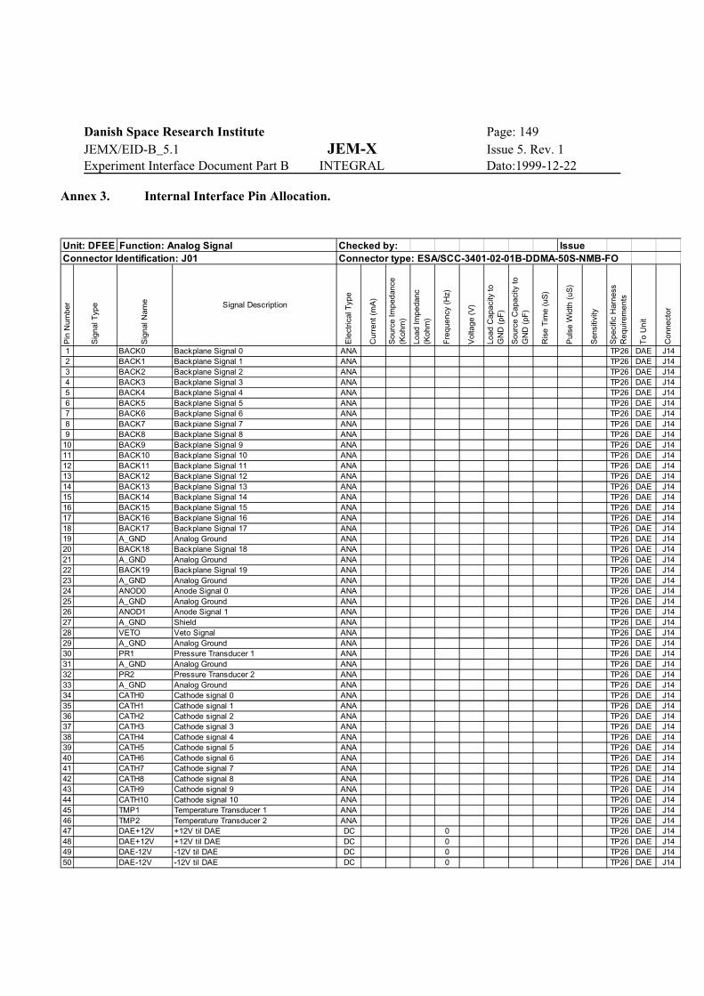
Danish Space Research Institute Page: 149JEMX/EID-B_5.1 JEM-X Issue 5. Rev. 1Experiment Interface Document Part B INTEGRAL Dato:1999-12-22
Annex 3. Internal Interface Pin Allocation.
Unit: DFEE Function: Analog Signal Checked by: IssueConnector Identification: J01 Connector type: ESA/SCC-3401-02-01B-DDMA-50S-NMB-FO
Pin
Num
ber
Sig
nal T
ype
Sig
nal N
ame Signal Description
Ele
ctric
al T
ype
Cur
rent
(m
A)
Sou
rce
Impe
danc
e (K
ohm
)
Load
Impe
danc
(K
ohm
)
Fre
quen
cy (
Hz)
Vol
tage
(V
)
Load
Cap
acity
to
GN
D (
pF)
Sou
rce
Cap
acity
to
GN
D (
pF)
Ris
e T
ime
(uS
)
Pul
se W
idth
(uS
)
Sen
sitiv
ity
Spe
cific
Har
ness
R
equi
rem
ents
To
Uni
t
Con
nect
or
1 BACK0 Backplane Signal 0 ANA TP26 DAE J142 BACK1 Backplane Signal 1 ANA TP26 DAE J143 BACK2 Backplane Signal 2 ANA TP26 DAE J144 BACK3 Backplane Signal 3 ANA TP26 DAE J145 BACK4 Backplane Signal 4 ANA TP26 DAE J146 BACK5 Backplane Signal 5 ANA TP26 DAE J147 BACK6 Backplane Signal 6 ANA TP26 DAE J148 BACK7 Backpiane Signal 7 ANA TP26 DAE J149 BACK8 Backplane Signal 8 ANA TP26 DAE J14
10 BACK9 Backplane Signal 9 ANA TP26 DAE J1411 BACK10 Backplane Signal 10 ANA TP26 DAE J1412 BACK11 Backplane Signal 11 ANA TP26 DAE J1413 BACK12 Backplane Signal 12 ANA TP26 DAE J1414 BACK13 Backplane Signal 13 ANA TP26 DAE J1415 BACK14 Backplane Signal 14 ANA TP26 DAE J1416 BACK15 Backplane Signal 15 ANA TP26 DAE J1417 BACK16 Backplane Signal 16 ANA TP26 DAE J1418 BACK17 Backplane Signal 17 ANA TP26 DAE J1419 A_GND Analog Ground ANA TP26 DAE J1420 BACK18 Backplane Signal 18 ANA TP26 DAE J1421 A_GND Analog Ground ANA TP26 DAE J1422 BACK19 Backplane Signal 19 ANA TP26 DAE J1423 A_GND Analog Ground ANA TP26 DAE J1424 ANOD0 Anode Signal 0 ANA TP26 DAE J1425 A_GND Analog Ground ANA TP26 DAE J1426 ANOD1 Anode Signal 1 ANA TP26 DAE J1427 A_GND Shield ANA TP26 DAE J1428 VETO Veto Signal ANA TP26 DAE J1429 A_GND Analog Ground ANA TP26 DAE J1430 PR1 Pressure Transducer 1 ANA TP26 DAE J1431 A_GND Analog Ground ANA TP26 DAE J1432 PR2 Pressure Transducer 2 ANA TP26 DAE J1433 A_GND Analog Ground ANA TP26 DAE J1434 CATH0 Cathode signal 0 ANA TP26 DAE J1435 CATH1 Cathode signal 1 ANA TP26 DAE J1436 CATH2 Cathode signal 2 ANA TP26 DAE J1437 CATH3 Cathode signal 3 ANA TP26 DAE J1438 CATH4 Cathode signal 4 ANA TP26 DAE J1439 CATH5 Cathode signal 5 ANA TP26 DAE J1440 CATH6 Cathode signal 6 ANA TP26 DAE J1441 CATH7 Cathode signal 7 ANA TP26 DAE J1442 CATH8 Cathode signal 8 ANA TP26 DAE J1443 CATH9 Cathode signal 9 ANA TP26 DAE J1444 CATH10 Cathode signal 10 ANA TP26 DAE J1445 TMP1 Temperature Transducer 1 ANA TP26 DAE J1446 TMP2 Temperature Transducer 2 ANA TP26 DAE J1447 DAE+12V +12V til DAE DC 0 TP26 DAE J1448 DAE+12V +12V til DAE DC 0 TP26 DAE J1449 DAE-12V -12V til DAE DC 0 TP26 DAE J1450 DAE-12V -12V til DAE DC 0 TP26 DAE J14
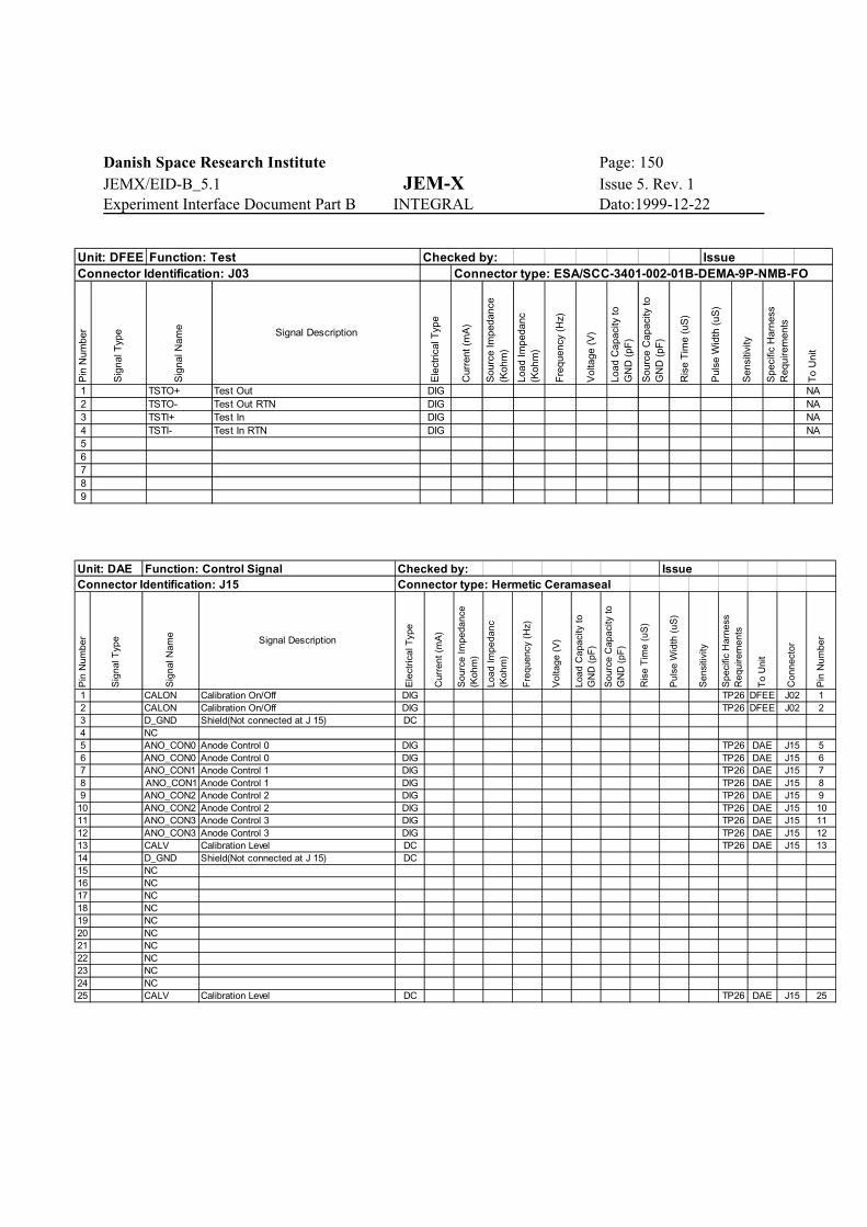
Danish Space Research Institute Page: 150JEMX/EID-B_5.1 JEM-X Issue 5. Rev. 1Experiment Interface Document Part B INTEGRAL Dato:1999-12-22
Unit: DFEE Function: Test Checked by: IssueConnector Identification: J03 Connector type: ESA/SCC-3401-002-01B-DEMA-9P-NMB-FO
Pin
Num
ber
Sig
nal T
ype
Sig
nal N
ame Signal Description
Ele
ctric
al T
ype
Cur
rent
(m
A)
Sou
rce
Impe
danc
e (K
ohm
)
Load
Impe
danc
(K
ohm
)
Fre
quen
cy (
Hz)
Vol
tage
(V
)
Load
Cap
acity
to
GN
D (
pF)
Sou
rce
Cap
acity
to
GN
D (
pF)
Ris
e T
ime
(uS
)
Pul
se W
idth
(uS
)
Sen
sitiv
ity
Spe
cific
Har
ness
R
equi
rem
ents
To
Uni
t
1 TSTO+ Test Out DIG NA2 TSTO- Test Out RTN DIG NA3 TSTI+ Test In DIG NA4 TSTI- Test In RTN DIG NA56789
Unit: DAE Function: Control Signal Checked by: IssueConnector Identification: J15 Connector type: Hermetic Ceramaseal
Pin
Num
ber
Sig
nal T
ype
Sig
nal N
ame
Signal Description
Ele
ctric
al T
ype
Cur
rent
(m
A)
Sou
rce
Impe
danc
e (K
ohm
)
Load
Impe
danc
(K
ohm
)
Fre
quen
cy (
Hz)
Vol
tage
(V
)
Load
Cap
acity
to
GN
D (
pF)
Sou
rce
Cap
acity
to
GN
D (
pF)
Ris
e T
ime
(uS
)
Pul
se W
idth
(uS
)
Sen
sitiv
ity
Spe
cific
Har
ness
R
equi
rem
ents
To
Uni
t
Con
nect
or
Pin
Num
ber
1 CALON Calibration On/Off DIG TP26 DFEE J02 12 CALON Calibration On/Off DIG TP26 DFEE J02 23 D_GND Shield(Not connected at J 15) DC4 NC5 ANO_CON0 Anode Control 0 DIG TP26 DAE J15 56 ANO_CON0 Anode Control 0 DIG TP26 DAE J15 67 ANO_CON1 Anode Control 1 DIG TP26 DAE J15 78 ANO_CON1 Anode Control 1 DIG TP26 DAE J15 89 ANO_CON2 Anode Control 2 DIG TP26 DAE J15 9
10 ANO_CON2 Anode Control 2 DIG TP26 DAE J15 1011 ANO_CON3 Anode Control 3 DIG TP26 DAE J15 1112 ANO_CON3 Anode Control 3 DIG TP26 DAE J15 1213 CALV Calibration Level DC TP26 DAE J15 1314 D_GND Shield(Not connected at J 15) DC15 NC16 NC17 NC18 NC19 NC20 NC21 NC22 NC23 NC24 NC25 CALV Calibration Level DC TP26 DAE J15 25
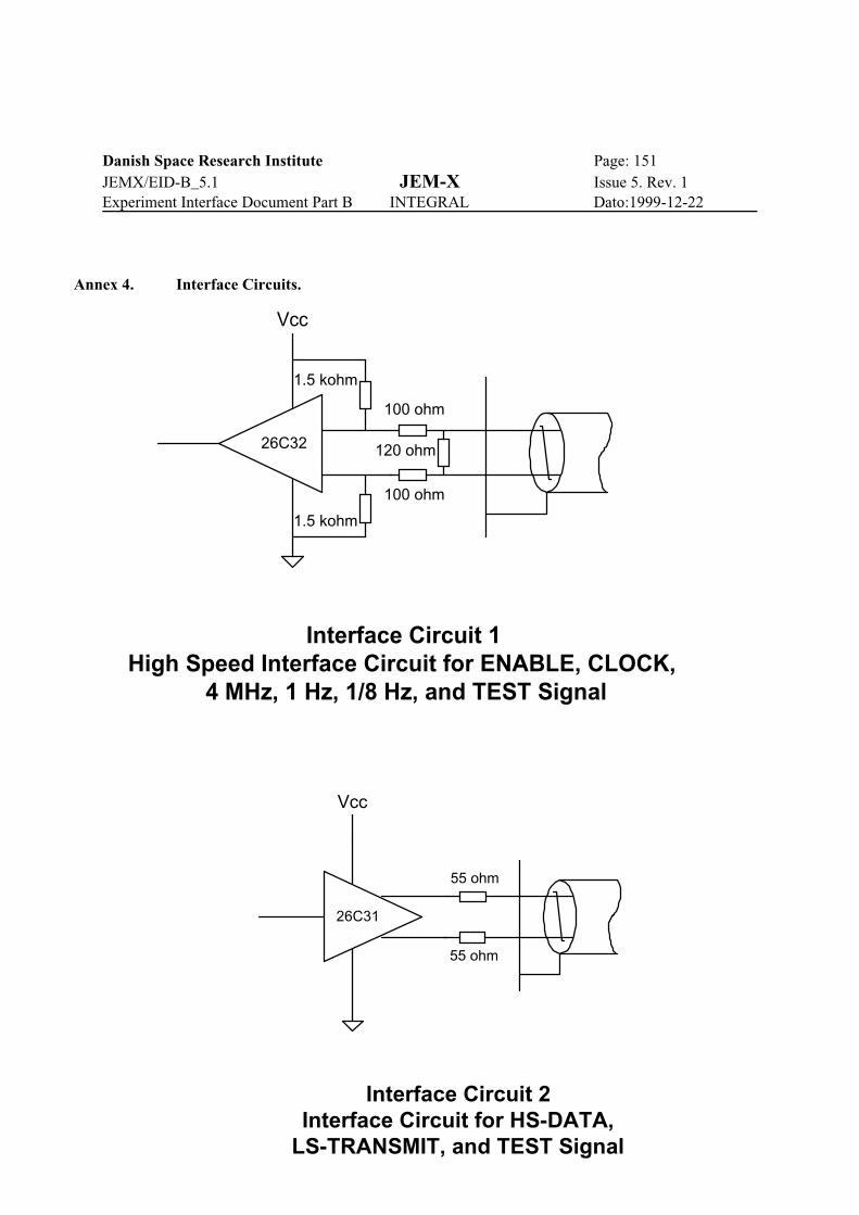
Danish Space Research Institute Page: 151JEMX/EID-B_5.1 JEM-X Issue 5. Rev. 1Experiment Interface Document Part B INTEGRAL Dato:1999-12-22
Interface Circuit 2Interface Circuit for HS-DATA,
LS-TRANSMIT, and TEST Signal
55 ohm
Vcc
55 ohm
26C31
Annex 4. Interface Circuits.
120 ohm
100 ohm
100 ohm
1.5 kohm
1.5 kohm
Interface Circuit 1High Speed Interface Circuit for ENABLE, CLOCK,
4 MHz, 1 Hz, 1/8 Hz, and TEST Signal
Vcc
26C32
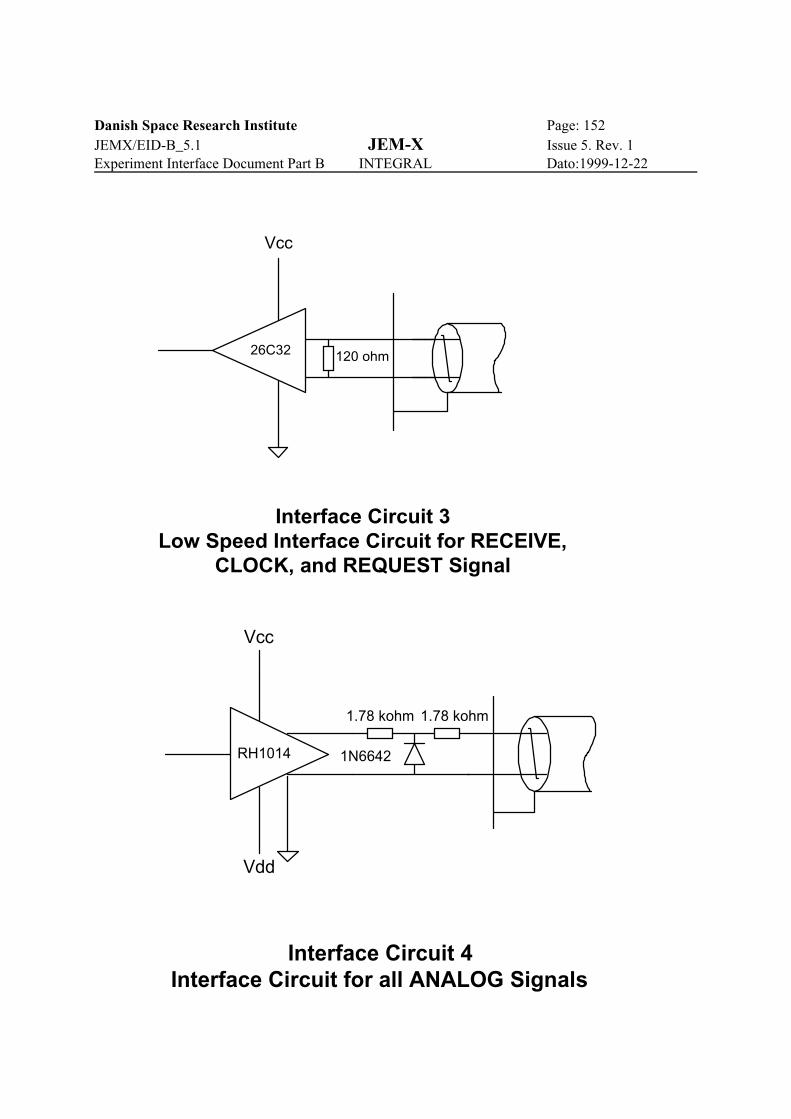
Danish Space Research Institute Page: 152JEMX/EID-B_5.1 JEM-X Issue 5. Rev. 1Experiment Interface Document Part B INTEGRAL Dato:1999-12-22
Interface Circuit 3Low Speed Interface Circuit for RECEIVE,
CLOCK, and REQUEST Signal
Vcc
26C32 120 ohm
Interface Circuit 4Interface Circuit for all ANALOG Signals
1.78 kohm
Vcc
1.78 kohm
RH1014 1N6642
Vdd

Danish Space Research Institute Page: 153JEMX/EID-B_5.1 JEM-X Issue 5. Rev. 1Experiment Interface Document Part B INTEGRAL Dato:1999-12-22
Interface Circuit 6HV OFF Command Interface from RTU
1 nF
+5V
HC14
150 ohm
500 ohm
1 kohm
5.1V
27 kohm
3C91
2N2222
100 ohm3C91
1N6317
text
Interface Circuit 5HV OFF Command Interface from DPE
100 ohm
+5V
HC132
100 ohm
619 ohm
1.54 kohm
681 ohm
5.1V16
.9 k
ohm
3C91
2N2222
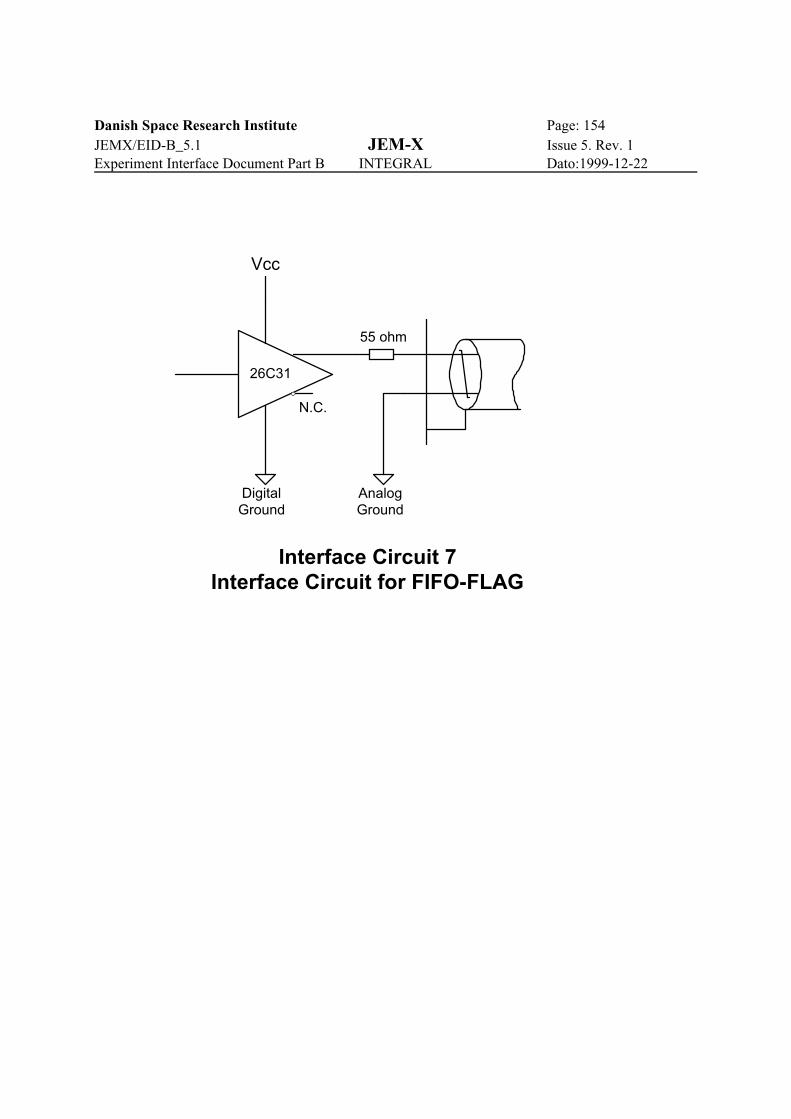
Danish Space Research Institute Page: 154JEMX/EID-B_5.1 JEM-X Issue 5. Rev. 1Experiment Interface Document Part B INTEGRAL Dato:1999-12-22
Interface Circuit 7Interface Circuit for FIFO-FLAG
Vcc
55 ohm
26C31
N.C.
DigitalGround
AnalogGround

Danish Space Research Institute Page: 155JEMX/EID-B_5.1 JEM-X Issue 5. Rev. 1Experiment Interface Document Part B INTEGRAL Dato:1999-12-22