joint institute for high temperatures ... -...
TRANSCRIPT

Shock, ablation and formation of nanostructures in metals induced by femtosecond laser
S.I. Ashitkov, P.S.Komarov, N.A. Inogamov, V.V. Zhakhovsky, M.B. Agranat, G.I. Kanel
Joint Institute for High TemperaturesRussian Academy of Sciences, MoscowJIHT of RAS
Santa Fe, NM, USA, April 21-25, 2014

2
MOTIVATION
Laser matter interaction/ experiment and modeling
Materials behavior near the theoretical limit of shear and bulk strength
Development of a theory of plasticity and fracture
Femtosecond laser surface nanostructuring
OUTLINE
Shock compression of aluminum and iron in picosecond range.- - super elastic shock waves at submicron scale - - achievement of ultimate values of the shear and bulk strength -- - possibility of α→ε polymorphic phase transition in iron
Frontal ablation and rear side spallation of aluminum.
Formation of nanostructures: MD simulations and experiment
JIHT of RAS

2
Shock compression of metals. Appearance of material properties in a free surface history. Shock wave structure.
Diagnostics of shock phenomena areperformed by measuring a free surfacevelocity profile of a tested sample.Free surface velocity history
In plate impact experiment*.
*G.I. Kanel', V. E. Fortov,S.V. Razorenov Physics-Uspekhi 50, (8) (2007)
Time t, µs
Free
Sur
face
Vel
ocity
ufs
, km
/s
13 GPa
∆ufs
Armco-iron2.46 mm
α→ε polymorphic phase transition in iron: (bcc → hcp crystal structure transition)Transition stress ≈13GPa in a microsecond range
Reflection of shock compression pulse from thefree surface leads to appearance of the tensile stresses inside of the sample causing fracture.Value of spall strength is determined from:
2/0efs
eSHEL uU ∆= ρσ
Splitting of shock wave into elastic precursor (HEL) andplastic compression wave makes it possible todetermine the plasticflow stress of the material.
2/)(0 δρσ +∆= fsSspall uU
JIHT of RAS

Ultrafast Chirped Pulse Interferometry
00.511.52.02.5
0 200
0
100
200
Time, ps
Posi
tion
y, µ
m
Phase shift, rad
100
-Detected range 0 ÷ 240 ps-Temporal resolution 1ps-Lateral spatial resolution 2 µm-Displacement accuracy 1÷2 nm-Measurements in a single shot
Amplifier CompressоrStretcherOscillator
Probe 300 ps8 0 1 0 0 1 2 0 1 4 0 1 6 0 1 8 0 2 0 0
- 1 , 0
- 0 , 5
0 , 0
0 , 5
1 , 0
C
A
Sample
CCD
Pump 100 fs
ImagingSpectrometerActon 2300i
ImagingMichelson
interferometr
Femtosecond Ti:S laser (Legend, Coherent, USA)
Time t, ps
790810 770
0 80 160 240
Probe wavelength, nm
Time t, ps
790810 770
0 80 160 240
Probe wavelength, nm
JIHT of RAS
In contrast to multipulse pump–probemethods the single-pulse techniqueensures much higherreliability of themeasurements and can be used toanalyze the reproducibility and statisticsof shock wave phenomena in thin filmsamples.
Application of Fourier processing ofinterference patterns and comparison of phase distributions obtained before and during shock wave arrival ensure measurement of surface displacement
with nanometric accuracy.
2D Fourier processing of interference patterns
Spatial-temporal phase distribution

Time and spatial resolved diagnostics of a rear surface displacement
Samples: metallic films, deposited by magnetron spattering onto glass substrates of 150 µm in thick
),( tyϕ∆Phase distributions at the rearsurface of iron targets of different thicknesses after shock breakout
d1
d2
pump100 fs
chirped probe300 ps
80 100120140160180200
-
-0,5
0,5
1
C
Ti:S laser
Glass substrate
Metal film
Gaussian spot Ø=40 µm
Phas
e shif
t, rad
2000 100
0.51
1.52
0
0.51
1.52
0250
0
200150
50100
250
0
200150
50100
Time t, ps
Posit
ion y,
a.u.
Fe, 250 nm
Fe, 540 nm
0 50 100 150 200 250
0
50
100
150
Dis
plac
emen
t, nm
Time t, ps
Al 500 nm
1200 nm
Free surface displacement histories πϕλ 4/),()(),( tyttyz ∆=∆
JIHT of RAS

2
Elastic-plastic shock wave in iron
0 50 100 150 2000,0
0,2
0,4
0,6
0,8
1,0
1,2
1,4
540 nmFe Shot # 8
Free
Sur
face
Vel
ocity
, km
/s
Time, ps
HEL
PSW
Splitting of shock into elastic-plastic two-wave configuration at propagation distance of 540 nm
Free surface displacement and velocity history at different stressTi:S laser: 100fs, 3 J/cm
0 50 100 150 200
0
20
40
60
80
100
Dis
plac
emen
t z, n
m
Time t, ps
Fe, Shot#8540 nm
Sample: 99.9 purity iron film 540 nm in thickdeposited on glass substrate
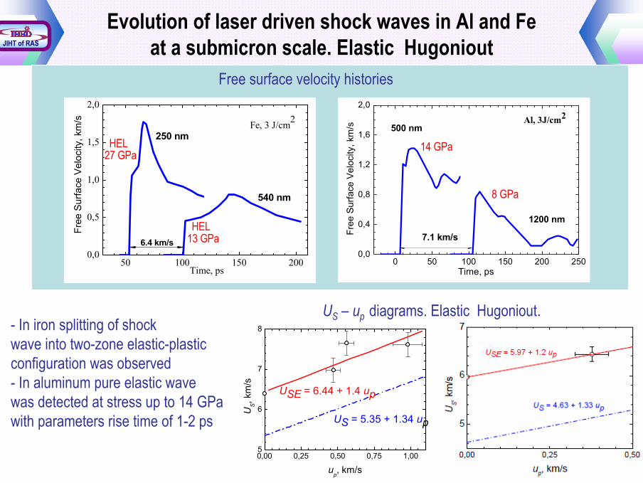
Evolution of laser driven shock waves in Al and Fe at a submicron scale. Elastic Hugoniout
0 50 100 150 200 2500,0
0,4
0,8
1,2
1,6
2,0
Fre
e Su
rface
Vel
ocity
, km
/s
Time, ps
500 nm
1200 nm
Al, 3J/cm2
7.1 km/s
8 GPa
14 GPa
50 100 150 2000,0
0,5
1,0
1,5
2,0
Fe, 3 J/cm2
250 nm
540 nm
Free
Sur
face
Vel
ocity
, km
/s
Time, ps
6.4 km/s
HEL
HEL27 GPa
13 GPa
Free surface velocity histories
0,00 0,25 0,50 0,75 1,005
6
7
8
US = 5.35 + 1.34 up
USE = 6.44 + 1.4 up
US,
km
/s
up, km/s
- In iron splitting of shock wave into two-zone elastic-plastic configuration was observed- In aluminum pure elastic wavewas detected at stress up to 14 GPawith parameters rise time of 1-2 ps
US – up diagrams. Elastic Hugoniout.
JIHT of RAS

P – V diagrams. Shear strength of aluminum and iron
7.5 GPaup to 7.9 GPaFe
3.4 GPaup to 3.2 GPaAl
Theoretical limitExperimental value
))()((43 VpVz −= στ
Recorded states in elastic shock waves (points) in aluminum and iron films
Maximum shear stress at uniaxial compression:
))()((43 VpVz −= στ
0,80 0,85 0,90 0,95 1,000
5
10
15
20
σz - p = 2.4 GPa τ = 1.8 GPa
Bulk:US = 5.35 + 1.34 up
Elastic: US = 6.44 + 1.4 up
σ, G
Pa
V/V0
σz - p = 4.3 GPa τ = 3.2 GPa
Al
JIHT of RAS
2
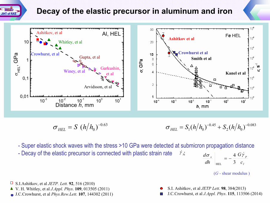
Decay of the elastic precursor in aluminum and iron
S.I. Ashitkov, et al JETP Lett. 98, 384(2013)J.C.Crowhurst, et al J.Appl. Phys. 115, 113506 (2014)
10-3 10-2 10-1 100 1010,01
0,1
1
10
Al, HELWhitley, et al
Gupta, et al
Ashitkov, et al
Garkushin, et al
Arvidsson, et al
Winey, et alσ HEL
, GPa
Distance h, mm
Crowhurst, et al
083.002
45.001 )()( −− += hhShhSHELσ63.0
0 )( −= hhSHELσ
Smith et al
Kanel et al
Ashitkov et al
Crowhurst et al
S.I.Ashitkov, et al JETP. Lett. 92, 516 (2010)V. H. Whitley, et al J.Appl. Phys. 109, 013505 (2011)J.C.Crowhurst, et al Phys.Rew.Lett. 107, 144302 (2011)
- Super elastic shock waves with the stress >10 GPa were detected at submicron propagation distance- Decay of the elastic precursor is connected with plastic strain rate :
l
px
cG
dhd γσ &
34
HEL
−=pγ&
(G - shear modulus )
JIHT of RAS
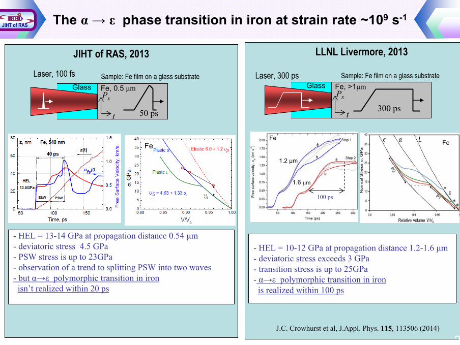
The α→ ε phase transition in iron at strain rate ~109 s-1
JIHT of RAS, 2013
Fe, 0.5 µm
Laser, 100 fs
t
Px
Glass
50 ps
Sample: Fe film on a glass substrate
Fe
- HEL = 13-14 GPa at propagation distance 0.54 µm- deviatoric stress 4.5 GPa- PSW stress is up to 23GPa- observation of a trend to splitting PSW into two waves- but α→ε polymorphic transition in ironisn’t realized within 20 ps
2
LLNL Livermore, 2013
Fe
- HEL = 10-12 GPa at propagation distance 1.2-1.6 µm- deviatoric stress exceeds 3 GPa- transition stress is up to 25GPa- α→ε polymorphic transition in ironis realized within 100 ps
J.C. Crowhurst et al, J.Appl. Phys. 115, 113506 (2014)
Fe, >1µmLaser, 300 ps
t
Px
Glass
300 ps
Sample: Fe film on a glass substrate
Fe
1.6 µm
1.2 µm
100 ps
JIHT of RAS
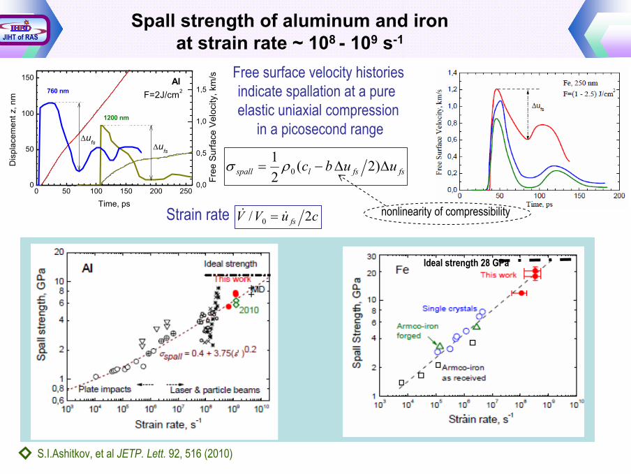
Spall strength of aluminum and iron at strain rate ~ 108 - 109 s-1
2
fsfslspall uubc ∆∆−= )2(21
0ρσ
cuVV fs 2/ 0 && =
S.I.Ashitkov, et al JETP. Lett. 92, 516 (2010)
nonlinearity of compressibilityStrain rate
Ideal strength 28 GPa
0 50 100 150 200 2500
50
100
150
0,0
0,5
1,0
1,5760 nmAl
1200 nm
Dis
plac
emen
t z, n
m
Time, ps
F=2J/cm2
∆ufs
Fre
e Su
rface
Vel
ocity
, km
/s
∆ufs
Free surface velocity historiesindicate spallation at a pure elastic uniaxial compression
in a picosecond range
JIHT of RAS
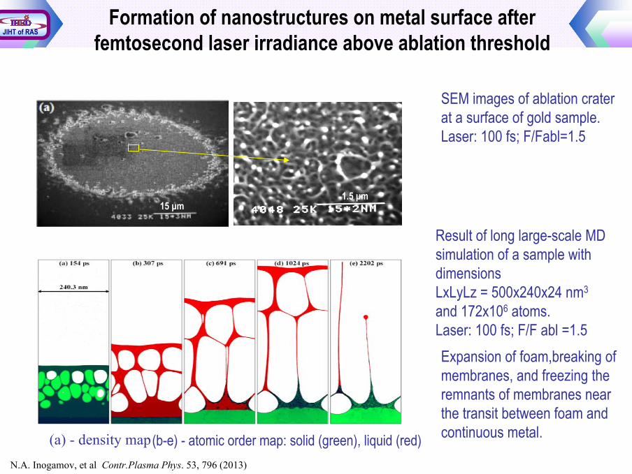
2N.A. Inogamov, et al Contr.Plasma Phys. 53, 796 (2013)
(a) - density map (b-e) - atomic order map: solid (green), liquid (red)
Expansion of foam,breaking ofmembranes, and freezing theremnants of membranes nearthe transit between foam andcontinuous metal.
Result of long large-scale MD simulation of a sample withdimensionsLxLyLz = 500x240x24 nm3
and 172x106 atoms.Laser: 100 fs; F/F abl =1.5
SEM images of ablation crater at a surface of gold sample.Laser: 100 fs; F/Fabl=1.5
Formation of nanostructures on metal surface afterfemtosecond laser irradiance above ablation threshold
15 µm1.5 µm
JIHT of RAS
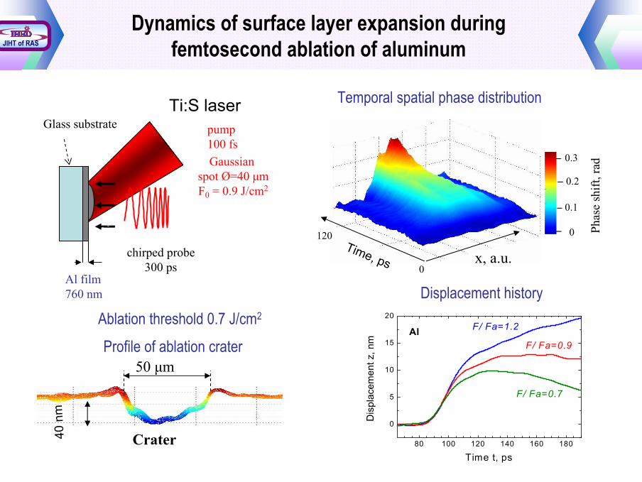
Dynamics of surface layer expansion during femtosecond ablation of aluminum
2
chirped probe300 ps
80 100120140160180200
-
-0,5
Glass substrate
Al film760 nm
Ti:S laserpump100 fsGaussian
spot Ø=40 µmF0 = 0.9 J/cm2
0
0.1
0.2
0.3
Phas
e sh
ift, r
ad
x, a.u.Time, ps 0
120
Temporal spatial phase distribution
80 100 120 140 160 180
0
5
10
15
20
Dis
plac
emen
t z, n
m
Time t, ps
F/ Fa=1.2
F/ Fa=0.9
F/ Fa=0.7
Al
40 n
m
Crater
50 µmProfile of ablation crater
Displacement history
JIHT of RAS
Ablation threshold 0.7 J/cm2

Frontal and rear side spallation in aluminum
500 1000 1500 2000 2500 30004
6
8
10
12
14
16
ρ c
10
5 , gc
m-2
c-1
T, K
Tm=933 K
AlSolid
Liquid
452.5±0.53· 1093.62.16Liquid (2kK)2507.7±0.52· 1096.42.71Solid (300 K)
LSpall, nmσSpall,, GPa, s-1c, km/sρ, gccAl
2/)( maxmin ttcLspall −=
Map of local atomic order
Frontal and rear surface velocity history
experimentMD
2/ucspall ∆= ρσ
Frontal surface Rear surface
JIHT of RAS
ε&
cu fs 2&& =ε
0 50 100 150
0,0
0,2
0,4
0,6
0,8
1,0
1,2
1,4
∆u=0.65km/s
Sur
face
Vel
ocity
u, k
m/s
Time t, ps
Rear Surface
Al, 760nm
Frontal Surface
∆u=1 km/s
F=2.1 J/cm2
F=0.9 J/cm2
Ti:S laser, 100 fs
*
* N.A.Inogamov et al JETP Lett 91 (2010)

2
SUMMARY
Single shot interferometric diagnostics was realized to measure surface displacement history with temporal resolution of 1 ps.
Experimentally found that uniaxial shock compression in picosecond range is elastic up to stress of 14 GPa in aluminum and 27 GPa in iron.
The stressed states in aluminum and iron, very close to the values of ultimate shear and bulk strength were measured and implemented in picosecond range of load duration
The α→ε polymorphic phase transition in iron film of 540 nm in thick isn’t realized at a stress of 23 GPa within 20 ps after HEL
From the expansion surface history the value of tensile stress of about 2.5 GPa leads to spallation of liquid layer of aluminum just above the ablation threshold under femtosecond heating was measured.
The results of long large-scale MD simulations of nanostructures formation at metal surface after it’s irradiance of femtosecond laser is well similar to SEM images of ablation crater’s morphology
JIHT of RAS

2
Thank you for yourattention!