josé maría nougués, michael brodkorb and josep a. feliu
TRANSCRIPT

José María Nougués, Michael Brodkorb and Josep A. Feliu, Inprocess Technology, Spain,
detail how dynamic process simulation can be used for centrifugal compressor systems.
Reprinted from May 2012 Hydrocarbon EnginEEring

Over the past 10 years, the use of dynamic process simulation has been established as a reliable and effective tool to analyse transient behaviour of process systems.1, 2 Common examples for
application are:
n Dynamic models to support safety analyses (for example, plant blow down).3 – 5
n Virtual plant models for operator training.6, 7 n Dynamic models to support the design of (advanced)
process control systems.8 – 10
n Design and operation of pipelines and compressor systems.11, 12
Commercially available process simulation software tools (such Honeywell’s UniSim, AspenTech’s HYSYS, etc.) enable detailed dynamic plant models to be configured from standard model algorithm building blocks. Once built, these models are verified against plant or design data in order to validate the model predictions. The software tools allow the scaling of the level of detail of the dynamic model and, consequently, a major challenge of dynamic simulation is to select the right level of
detail in order to predict realistic behaviour without having to collect and use vast amounts of plant and design data.9
Dynamic behaviour of compressor systemsCentrifugal compressor systems show performance characteristics that mainly depend on the operating point imposed on them by the process units and the connection piping around the compressor.
Large compression systems often have several compressors operating in parallel, with some of them in standby. Therefore, even in normal operation there are frequent start up and shut down operations while switching between compressors: to accommodate throughput changes, for example. The transient analysis of these operations is critical to evaluate the dynamic behaviour of the compressor system and the associated control and safety systems.11
Frequently, the most important analysis carried out for compressor systems is to understand if the compressor system could enter into surge due to changes in the operating conditions, or due to shut down/start up of other compressors in the system. Surge occurs when the pressure head demanded by the process system cannot be supported by the pressure head versus flow performance characteristics of the compressor at the current operating speed.
The protection of the compressor against surge is essential. Surge situations can be overcome by varying the number of compressors in use and/or changing the recycle rate, thus moving the operating point in the performance map away from the surge line. This is accomplished by an integrated anti surge system, which monitors the performance of the compressor stage and opens a recycle valve as the machine approaches surge
Reprinted from May 2012Hydrocarbon EnginEEring
Reprinted from May 2012 Hydrocarbon EnginEEring
conditions. Surge controllers are designed to prevent surge, and (for complex systems) dynamic modelling can validate the surge control strategy.
Another aspect of the complexity of large compressor systems is the overlay of dynamic behaviour of the different compressors in the system with the dynamic behaviour of their respective drivers and the dynamic behaviour of the process connected to the compressor. Again, dynamic process simulation is an adequate tool to assess the influence of these transient effects on the compressor performance.
ApplicationsDynamic process simulation has proven a useful tool for a wide variety of analyses of compressor systems. It can be utilised during the design phase, as well as for troubleshooting and revamping of existing compression systems.12 Below are several application examples:
n Verification of the operating capability of the compression unit within the selected process scheme. Identification of potential problems and assessment of any required modifications, especially related to anti surge control valve (ASCV) sizing (Figures 1 and 2).
n Analysis of compressor start up: for example, after a compressor trip (high discharge pressures). Verification of start up procedure from hot stand by.
n Analysis of possible shut down and emergency shut down procedures, and determination of the impact on the other compressors in the system.
n Confirmation of the equipment design, including the designed protections and safety layers. Evaluate hot gas bypass and valve sizing (Figure 3).
n Assessment of the designed anti surge control (fitting the surge controller to the application).
n Optimisation of the current surge control line to minimise power consumption (i.e. optimisation of flow margin between surge and control lines according to defined criteria).
n Assessment of the performance controller and the load sharing system.
n Analysis of the location of the non-return valves. n Determination of settling out pressure, depressurisation time
estimation and blow down valve sizing. n Testing and verification of compressor and driver integration
with reference to transient behaviour during run down.
CharacteristicsModern dynamic process simulation software tools are capable of representing complex compressor systems with a sufficient degree of detail to support the aforementioned analysis types (Figure 4).
In the process simulator the compressor unit is normally modelled using a global parameters model for the fluid side, rigorously calculating the process conditions by following the isentropic line from inlet to outlet pressure. Using the enthalpy at that point, as well as the specified efficiency, the simulator then determines the actual outlet enthalpy. For an irreversible process, the work determined for the mechanically reversible process is multiplied or divided by an efficiency to give the actual work.
The compressor models are able to handle multiple compressor curves as a function of speed, as well as multiple compressor curves that describe the compressor performance as a function of inlet guide vain position. Other specification settings are also available, depending on the process simulation software (Figure 5).
The following mechanical and operational details are also normally considered:
n Inertia and friction loss. n Possibility to link compressors or turbines that are located
on the same shaft. n Specification of surge and stonewall curves. n Engine inertia and speed: torque curve for the electrical
engine can be represented and dynamic properties included.
In addition, it is usually possible to customise the model in order to allow for any application specific needs. For example, it is possible to include client specific surge control algorithms or existing client specific compressor models in the standard process simulation software.
BenefitsThe general benefit of applying dynamic simulation to compressor systems is to predict temperature peaks in advance, including their length, whether there is surge excursion, etc. In addition, it is possible to analyse how changes in the design (adding valves, changing position of valves, changing equipment size, etc.) impact such behaviour.
In some cases, performing a dynamic simulation study (DSS) can also help in defining the controller settings. This is beneficial because it is possible to commission the compressor with a set
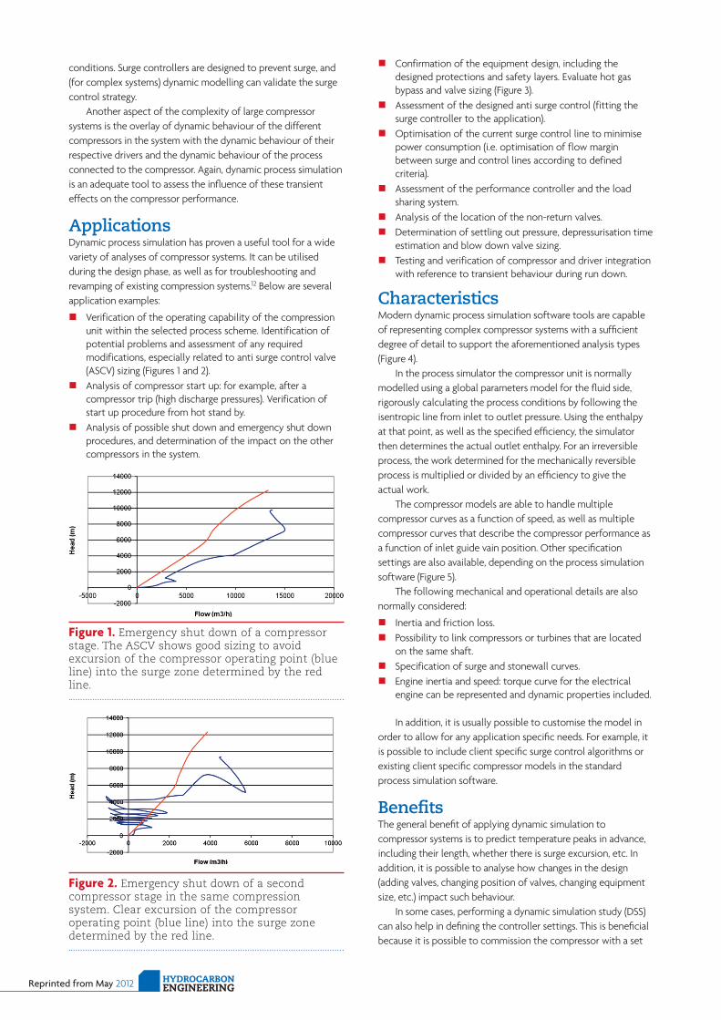
Figure 1. Emergency shut down of a compressor stage. The ASCV shows good sizing to avoid excursion of the compressor operating point (blue line) into the surge zone determined by the red line.
Figure 2. Emergency shut down of a second compressor stage in the same compression system. Clear excursion of the compressor operating point (blue line) into the surge zone determined by the red line.
Reprinted from May 2012Hydrocarbon EnginEEring
of preliminarily tested values for the controller set points and parameters, thus saving start up time.
Without dynamic simulation, all design decisions are based on identification of the extreme operating conditions and on attempts to calculate the size/settings for these conditions. For example, it is not possible to reliably predict a compressor’s surge line using steady state simulation. An idea can be gleaned based on the system’s inertia and the prevailing flow conditions, but such information is usually not fully conclusive, as it only gives indications about the sensitivity of the system to surge.
An additional benefit of compressor DSS is that the results of the DSS can help to justify engineering decisions that can have significant economic impact in the project. Of course, this depends on the scope of the engineering firm and the compressor manufacturer. An example would be the selection of the hot gas bypass valve. Based on experience with engineering companies and compressor manufacturers, performing selected dynamic scenarios in the early phase of the project can aid the decision to include (or exclude) additional protection or to change the check valve position. Both of these decisions can have significant economical impact on the project budget.
In one project, for example, the execution of the emergency shut down (ESD) analysis allowed users to identify that the hot gas bypass (HGB) was not necessary, and that the inclusion of the HGB would have resulted in an even worse situation, as the compressor could have moved into the stonewall region.
In another case, when the DSS was executed late in the project, the results showed that the check valve position should have been moved. As moving the valve was not possible by that point, the solution was to include an additional blow down line with significant cost impact.
Executing the DSS in the early phase of the project can have an economical benefit and also provide a solid basis for discussion and revision of any technical solutions. This therefore supports the communication between the engineering company and the end customer.
Optimal timeThere are essentially three opportunities during the engineering design of a compressor system when a compressor DSS would be suitable (Table 1). Each of these timings would serve a different objective, with different modelling focus, modelling detail and data requirements:
n Initial study: once the required pressure increase is known.
n Intermediate study: once preliminary compressor curves are known.
n Detailed study: once the compressor has been built.
Initial study (FEED Phase)
Objectives n Towards the end of the FEED phase, dynamic simulation can
be applied to: § Check the main valve positions. § Estimate the settling out conditions. § Analyse the sensitivity of the system to certain changes
(volumes, heat exchangers, etc.). n Such information can be used to assess if one is at the limit
of the process or not, and this in turn can be used to: § Avoid problems that would appear later on during the
design phases, e.g. controllability issues that may become extremely complex and might force a reexecution of the HAZOP.
§ Make the appropriate decisions at the right time before further investments or economical commitments are made.
Data requirements n Estimated main equipment capacity/volumes. n Process conditions (pressure/temperature profile). n Main valve positions.
Intermediate study (EPC)
Objectives n Verification of the control narrative: i.e. that all control
actions and safety actions proposed will respond as planned.
n Before plant commissioning, it will also help to properly select the sensors to control the plant, reducing unexpected commissioning time. This will allow verifying the behaviour of the compressor system for different operation conditions.
n Alarm setting configuration: avoid unexpected plant trips due to an inappropriate alarm setting configuration.
n Verify the cause effect matrix. n Verification of size of certain critical equipment (e.g.
scrubber volumes, cooler maximum capacity) and determine the safety measure to protect the equipment (through control or protection valves) therefore saving money in resizing equipment that is already committed.
n Final verification of compressor driver sizing: for changes in operational conditions (driver overload).
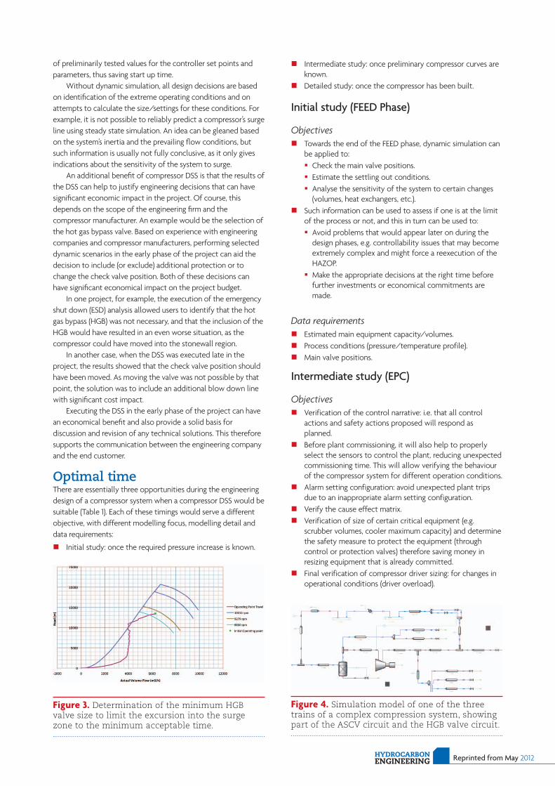
Figure 4. Simulation model of one of the three trains of a complex compression system, showing part of the ASCV circuit and the HGB valve circuit.
Figure 3. Determination of the minimum HGB valve size to limit the excursion into the surge zone to the minimum acceptable time.
n Sizing of anti hydrate formation lines. n Verify the proposed procedures of compressor start up and
shut down. n Evaluate the flaring conditions for different operating
scenarios, thus reducing the frequency of flaring conditions.
Data requirements n Piping isometrics/sizing. n Vessel/HX/valve sizing. n Preliminary compressor/pump/turbine curves . n Alarms settings. n Compressor start up and shut down logic. n Antisurge controller information. n Detailed start up and shut down procedures. n Control philosophy documents. n Cause and effect logic diagrams. n Process trip switch set point schedule.
Detailed study (commissioning)
Objectives n Real distributed control system (DCS) or programmable logic
control (PLC) presetting, thus reducing the commission time on installation site and the number of unexpected incidents during commissioning resulting in significant savings in man hours, raw material and avoidance of contractual penalties.
n Verification of the final emergency logic, reducing time and risk of the factory acceptance test (FAT) process.
n Evaluate accurately emissions, flare load, etc. and report to local authorities when required.
n The detailed model can be used to train operators on the real control system in front of emergency scenarios, leading to off the shelf (OTS) compressors.
n OTS benefits include: § Enhanced process operation understanding. § Optimised operator intervention. § Timesaving during start up and production regime
changes.
§ Standardise operator reactions to certain scenarios. § Conduct periodic refresher training and testing. § Certify operators for competence. § Support all kinds of operational conditions including
those far from the design operating points including abnormal and emergency situations.
§ Developing exercises to retain knowledge from the experienced workforce.
§ Develop, verify, and improve operating/maintenance procedures.
§ Conduct investigations into operating incidents. § Develop emergency response procedures.
Data requirements n Final ESD logic. n Control database for OTS. n Final configuration and performance curves of main
equipment (compressor curves, pump curves, etc.).
ConclusionCompressors represent a significant capital investment and operating expense, and are an essential component in providing revenue streams to a plant. Therefore, compressor operation and protection are critical issues in all phases of the project life cycle.
Dynamic simulation has become a powerful tool for leveraging simulation technology to assist in the design and operation of compressor systems. Through collaboration with equipment and control system suppliers, a high fidelity dynamic simulation can be developed as a value added tool, even at the early phases of a project. A dynamic model allows users to study the performance of compressor trains under the full range of operation and can eventually serve to improve compressor efficiency, availability and protection.
References1. Nougués, J.M. aNd PuigJaNer, L. 'Web-based process simulation'.
Xi european symposium on Computer aided Process engineering 41 - 46 (2001).
2. Nougués, J.M., rodríguez, J.C., saMa, s. & HoCkiNg, d. 'simulation, design and analysis'. Software Architecture and Tools for Computer Aided Process Engineering 127 – 164 (2002).
3. dePeW, C. & dessiNg, J. 'dynamic simulation improves Column relief-Load estimates'. Hydrocarbon Processing 81 – 86 (1999).
4. gruber, d. et al. 'are there alternatives to an expensive overhaul of a bottlenecked flare system?' Petroleum Technology Quarterly 93 – 95 (2010).
5. FeLiu, J.a. & aLós, M.a. 'alivio de presión en columnas de destilación de crudo'. Ingenieria Quimica 102 – 107 (2008).
6. CoNtreras, J. & Ferrer, J.M. 'dynamic simulation?: a case study'. Hydrocarbon Engineering (2005).
7. MaCías-HerNáNdez, J.J. & FeLiu, J.a. 'dynamic simulation and oPC'. Hydrocarbon Engineering (2003).
8. aLsoP, N. & Ferrer, J.M. 'avoiding plant tests with dynamic simulation'. Hydrocarbon Processing 47 – 52 (2008).
9. goNzáLez, r. & Ferrer, J.M. 'analyzing the value of first- principles dynamic simulation'. Hydrocarbon Processing 69 – 75 (2006).
10. HoWard, r., osta, s., Niekerk, F.V. & Ferrer, J.M. 'extending aPC benefits'. Hydrocarbon Engineering (2007).
11. botros, k.k. & gaNesaN, s.t. 'dynamic instabilities in industrial Compression systems with Centrifugal Compressors'. thirty-seventh turbomachinery symposium 119 – 132 (2008).
12. PateL, V., FeNg, J., dasguPta, s., raMdoss, P. & Wu, J. 'application of dynamic simulation in the design, operation and troubleshooting of Compressor systems'. thirthy-sixth turbomachinery symposium 95 – 105 (2007).
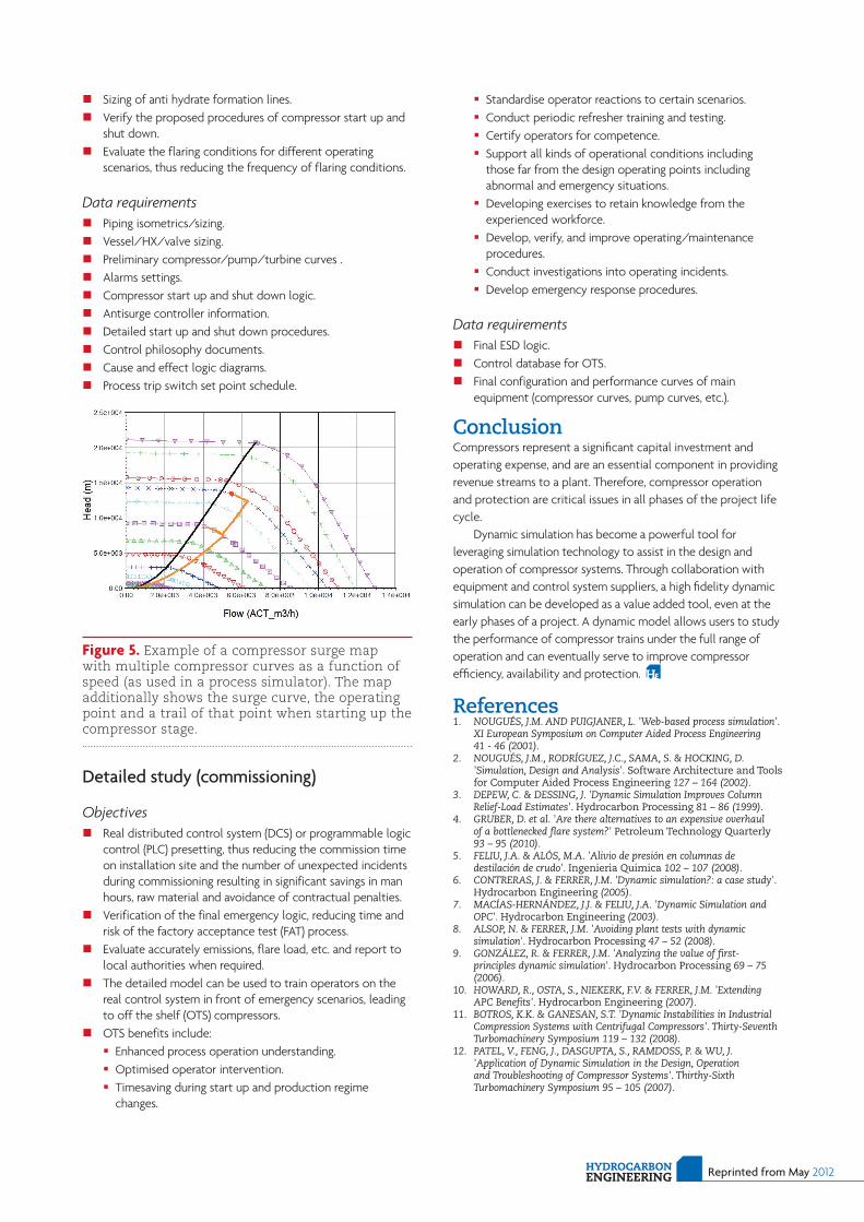
Figure 5. Example of a compressor surge map with multiple compressor curves as a function of speed (as used in a process simulator). The map additionally shows the surge curve, the operating point and a trail of that point when starting up the compressor stage.
Reprinted from May 2012Hydrocarbon EnginEEring