journal bearingdesign
TRANSCRIPT

This page has been reformatted by Knovel to provide easier navigation.
13 Bearings andbearing metals
Contents
13.1 Introduction 331
13.2 Bearing design 33113.2.1 Wall thickness 33113.2.2 Interference fit 33113.2.3 Locating tangs 33213.2.4 Free spread 33213.2.5 Loading on crankpin and main bearings 33313.2.6 Prediction of oil film thickness 33313.2.7 Grooving configuration 33413.2.8 Clearance 335
13.3 Bearing damage 33513.3.1 Abrasion 33513.3.2 Fatigue 33613.3.3 Corrosion 33613.3.4 Wiping 33713.3.5 Cavitation 33713.3.6 Fretting 33713.3.7 Design faults 33713.3.8 Incorrect assembly 33813.3.9 Environmental factors 33813.3.10 Geometric factors 339
13.4 Slow-speed engine crosshead bearings 339
13.5 Bearing metals 34013.5.1 Fatigue strength 34013.5.2 Scuff resistance 34013.5.3 Wear resistance 34113.5.4 Cavitation erosion resistance 34113.5.5 Overlays 34113.5.6 White metals 34213.5.7 Copper-lead and lead-bronze alloys 34313.5.8 Aluminium-tin alloys 34413.5.9 Aluminium-silicon alloys 345
References 345

13.1 Introduction
Any bearing can be simply defined as a support or guide whichat the same time allows relative movement to take place betweentwo bodies. In a diesel engine, the principal bearings are thosewhich allow rotation of the crankshaft about its own longitudinalaxis in the main engine entablature, and those between theconnecting rod and crankshaft. In modern engine terminologya bearing has come to mean the component fitted between thejournal and either the main bearing housing or the connectingrod, the shaft being supported in the bearing via an oil film.Figure 13.1 indicates the interaction between the variouscomponents in any engine bearing assembly, and the environmentwithin which the bearing system must operate1.
The co-operating surface, the lubricant and the environmentall place constraints on the bearing, the resulting design usuallybeing a compromise between various conflicting requirements.In relation to the bearing itself, the choice is usually restrictedto material and geometry. However, environmental factors haveto be taken into serious consideration at the design stage if areliable system is to be achieved.
13.2 Bearing design
13.2.1 Wall thickness
To achieve optimum utilization of space, reliability and re-peatability of the bearing assembly, thin shell bearings havebeen almost universally adopted in modern diesel engines, andfitted retrospectively into many older engines. Such a bearingallows the use of a wider range of surface lining materials thanwould otherwise be possible.
The thin shell bearing is a precision made pre-finishedcomponent consisting of a steel backing with a thin coating ofthe most appropriate lining material necessary to provide sufficientstrength for the applied loading and compatibility with the generalenvironment. The overall thickness/diameter ratio is not critical,but typically varies from 0.05 at 40 mm diameter to 0.02 at 400mm as shown by Figure 13.2.
13.2.2 Interference fit2
The assembled form of a thin shell bearing is dictated by the
Housing diameter [mm]
Figure 13.2 Wall thickness/diameter for thin wall bearings
tolerance to which it can be manufactured, and by the housinginto which it fits. To ensure conformity of the bearing shell toits housing, an accurate interference fit has to be provided. Thisis obtained by means of an excess peripheral length in eachhalf-bearing which has to be closely prescribed to allow inter-changeability, requiring precise quality control of every half-bearing in a checking fixture (Figure 13.3}. On assembly theexcess peripheral length creates a circumferential stress aroundthe bearing, and a radial contact pressure between the bearingback and the housing bore. This contact pressure resists relativemovement, thus preventing fretting. Unfortunately, there is notheoretically correct level; housings with high flexibility requiremore contact pressure than stiffer ones. On early engines, havingthin shell bearings, a contact pressure as low as 2MPa wasusually sufficient to resist fretting, but as engine ratings increased,and housing stress analysis became more sophisticated, higherpressures became necessary, often reaching 8-10 MPa today. Inthese very high interference fit assemblies, particular care hasto be taken to ensure that the joint face clamping bolts havesufficient capacity to assemble the bearing, and to resist dynamicseparating forces generated by engine operation.
As the contact pressure is increased for any given bearingsize, the circumferential stress increases to the point where the
Crossheadbearings
ISO range
Wal
l thi
ckne
ss [
mm
]
Figure 13.1 The bearingsystem-interaction betweencomponents and environment
Surface 1Bearing
Surface 2Shaft
Geometric Form1. Dimensional2. Surface finish3. Features
Material1. Composition2. Strength3. Hardness4. Compatibility5. Corrosion
resistance
Lubricant1. Viscosity
(coefficient of)2. Stability3. Compatibility4. Adhesion5. 'Oiliness'6. Bulk modulus7. Additives
Geometric Form1. Dimensional2. Surface finish3. Bore profile4. Features
Material1. Composition2. Strength and ductility3. Fatigue strength4. Compatibility
(seizure resistance)5. Conformability6. Embeddability7. Corrosion resistance
AppliedResultant
1. Minimum filmthickness (hmin)
2. 'Friction' generatedheat
3. Power loss4. Bearing temperature5. Lubrication outlet
temperature
6. Lubricant supplypress, and temp.
7. Heat removal8. Contamination9. Vibration
10. Electricalpotential
1. Load cycle2. Sliding velocity3. Temperature4. Clearance5. Supporting housing
(a) Dimensional(b) Distortion(c) Alignment

Figure 13.3 Checking peripheral length of a thin shell bearing
steel backing begins to yield adjacent to the joint faces. Knowingthe combined effect of bearing steel yield strength and the frictionforce for bearing assembly, a wall thickness can be determinedwhich will avoid yield, although in some automotive-type enginesthis may not be feasible.
Increased contact pressure requires a greater bolt tension forfitting bearing caps to their opposite half-housings, and as highervalues are incorporated, measurement checks should be carriedout on prototype assemblies to ensure that satisfactory closureof the housing joints occurs. Figure J3.4 shows a convenientmethod of checking this closure, the micrometer readings beingtaken as the bolt load is gradually increased. Insufficient boltpre-load would result in fretting between the bearing and housing,and could allow the housing joints to separate, giving rise tohigh dynamic loading of the bolts, with possible fatigue fracture.
To reduce the tendency to fretting, it is recommended that thecentre line average (CLA) of the housing bore surface finishshould not exceed 1.6 /^m. Bearing backs are typically 0.8 j^mCLA surface finish and, in highly loaded zones, should not beunsupported. Cyclic variation of hydrodynamic oil pressure on
the bearing surface will cause the bearing to flex in theseunsupported regions. If, for example, there are grooves or oilholes behind the bearing surface, fretting will almost certainlyoccur. If flexure is sufficiently great, the lining material on thebearing surface can also suffer fatigue damage. Figure 13.5shows fretting damage on the back caused by a combination ofinsufficient interference fit and lack of support. The resultingflexure has also caused the lining material on the bore surfaceto fatigue.
Provided a bearing is manufactured to the defined length andwall thickness limits, and the housing and bolting arrangementsare satisfactory, correct assembly should be achieved every time,with bearing shells being interchangeable. However, locatingtangs and free spread greatly assist correct assembly of thinshell bearings, particularly replacement in situ.
13.2.3 Locating tangs
Locating tangs allow correct axial positioning of bearing shellsthereby ensuring alignment of oil transfer passages and clearancebetween the ends of the bearing and crankshaft fillets. The tangis located in a corresponding recess in the housing and must bea clearance fit, otherwise the bearing surface may distort. It isalso advantageous to relieve the tang below the level of thebearing joint face, thus reducing localized pressure on the tangduring assembly.
Tangs are not intended to resist rotation of the bearing shell;that is achieved by the contact pressure. If, under seizure con-ditions, this contact pressure cannot prevent rotation, the tangsare either sheared or flattened.
13.2.4 Free spread
Free spread is the term given to the excess dimension across thebearing joints with the bearing in its free state, compared withthe housing diameter. This allows the bearing to be positivelylocated radially and should generate sufficient friction to holdthe shell in its housing even when inverted.
Following operation in an engine, bearings may show a lossof free spread on removal for the following reasons:
(i) The lining of a steel-backed bearing, because of its higherthermal expansion, can yield in compression at operatingtemperature producing a residual tensile stress when cooled toroom temperature. This effect becomes greater with higher liningto steel thickness ratio.(ii) A high radial temperature gradient across the steel backing,due to malfunction, can cause differential yield and thereforeadditional free spread loss.(iii) Relief of strains induced during fitting or by the manufacturingand machining processes.
Figure 13.5 Fatigue and fretting damage due to insufficient interferencefit and unsupported region of the bearing backFigure 13.4 Method of checking housing joint face closure
The forces which result in free spread loss after releasing thebearing from its housing are of relatively small magnitude andwill not cause malfunction of the bearing whilst in operation.Problems only arise upon reassembly, particularly if one halfhas negative and the other positive free spread. The half withthe negative free spread may become trapped against the shaftand lead to overheating or seizure. Therefore bearings withnegative free spread should not be refitted.
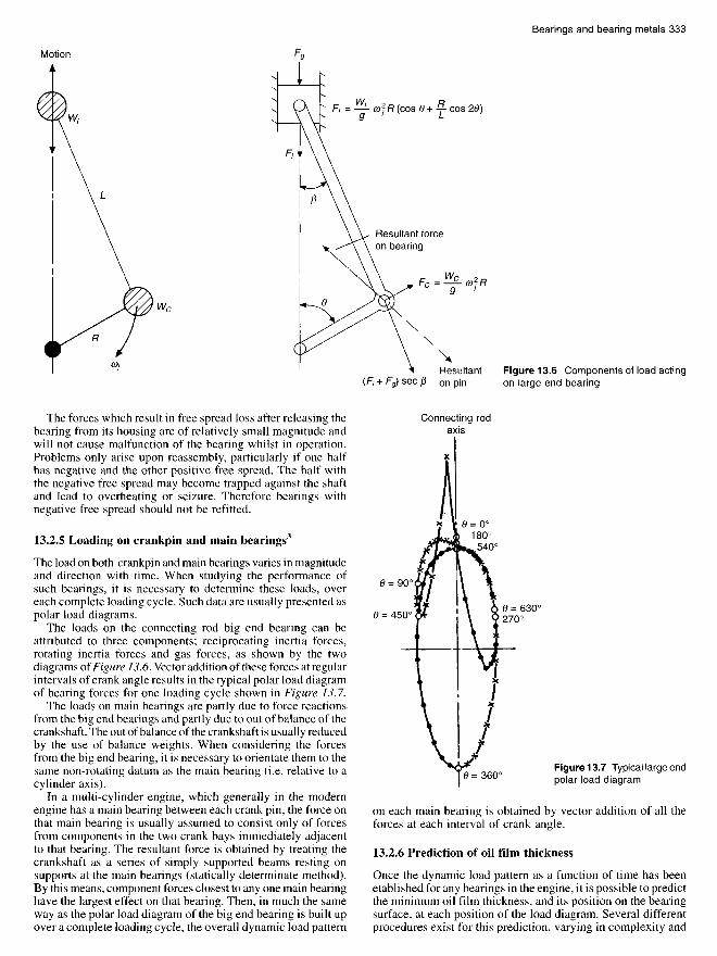
13.2.5 Loading on crankpin and main bearings3
The load on both crankpin and main bearings varies in magnitudeand direction with time. When studying the performance ofsuch bearings, it is necessary to determine these loads, overeach complete loading cycle. Such data are usually presented aspolar load diagrams.
The loads on the connecting rod big end bearing can beattributed to three components; reciprocating inertia forces,rotating inertia forces and gas forces, as shown by the twodiagrams of Figure 13.6. Vector addition of these forces at regularintervals of crank angle results in the typical polar load diagramof bearing forces for one loading cycle shown in Figure 13.7.
The loads on main bearings are partly due to force reactionsfrom the big end bearings and partly due to out of balance of thecrankshaft. The out of balance of the crankshaft is usually reducedby the use of balance weights. When considering the forcesfrom the big end bearing, it is necessary to orientate them to thesame non-rotating datum as the main bearing (i.e. relative to acylinder axis).
In a multi-cylinder engine, which generally in the modernengine has a main bearing between each crank pin, the force onthat main bearing is usually assumed to consist only of forcesfrom components in the two crank bays immediately adjacentto that bearing. The resultant force is obtained by treating thecrankshaft as a series of simply supported beams resting onsupports at the main bearings (statically determinate method).By this means, component forces closest to any one main bearinghave the largest effect on that bearing. Then, in much the sameway as the polar load diagram of the big end bearing is built upover a complete loading cycle, the overall dynamic load pattern
on each main bearing is obtained by vector addition of all theforces at each interval of crank angle.
13.2.6 Prediction of oil film thickness
Once the dynamic load pattern as a function of time has beenetablished for any bearings in the engine, it is possible to predictthe minimum oil film thickness, and its position on the bearingsurface, at each position of the load diagram. Several differentprocedures exist for this prediction, varying in complexity and
Motion
Resultant forceon bearing
Resultanton pin
Figure 13.6 Components of load actingon large end bearing
Connecting rodaxis
Figure 13.7 Typical large endpolar load diagram
hence in validity with the real case. Each method makes someattempt to solve Reynolds equation governing the performanceof hydrodynamic bearings. Some of the methods availableare:
(a) Hand calculation, using an equivalent speed concept4'5'6
(b) Graphical procedures for the complete locus, using mobilitymethods7.
(c) Approximate method to predict the minimum film thicknessin the cycle where 'squeeze intervals' predominate8.
(d) Computer methods which predict the complete journallocus?'9'10
(e) Inertia load studies"(f) Experimental results8.
All these methods are thoroughly reviewed by Campbell et<3/.8, but whilst each technique has specific advantages in particularcircumstances, those most generally employed involve the useof computer methods to predict the complete journal locus overthe whole of each loading cycle. The advantage of rapid, low-cost computer programs is that predicted results can be achievedand compared for a large number of different types and sizes ofengines at various operating conditions. With the greater flexibilityafforded by the use of computers, bearing analysis will continueto advance, but whilst it is already possible to give someconsideration to housing, crankshaft and bedplate distortion,the most common computer techniques still treat the crankshaftas a series of simply supported beams. For medium- and slow-speed engines, this is probably realistic due to the high crankshaftstiffnesses demanded by stress limits, and the high standard ofbearing alignment enabled by current machine tools andproduction methods.
Other basic assumptions usually include: perfect alignmentof shaft and bearing through the loading cycle; truly circularshaft and bearing; infinitely rigid bearing housing and journal;viscosity unaffected by variations of temperature and pressurearound the bearing and through the cycle; and that negative oilfilm pressures can be neglected.
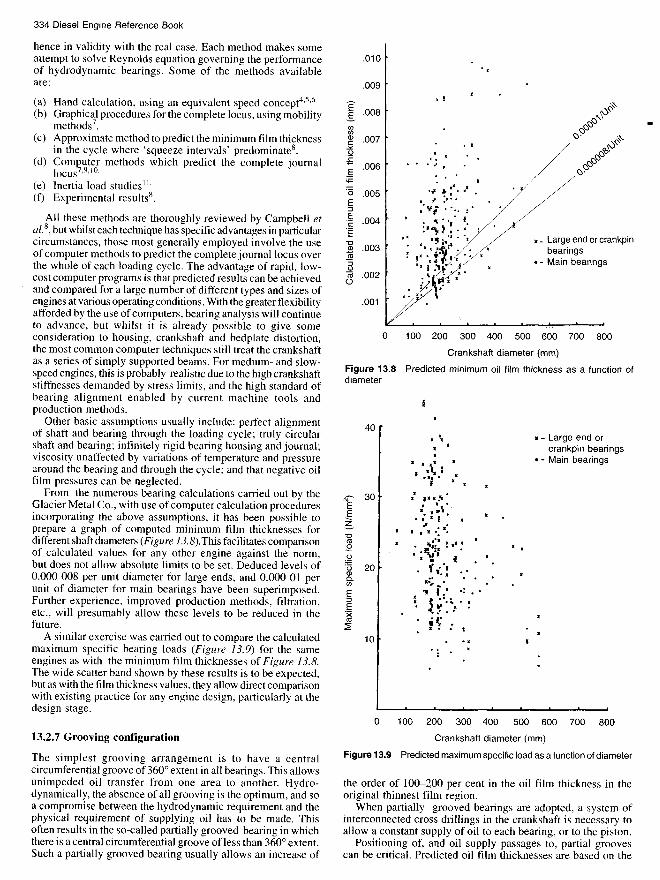
From the numerous bearing calculations carried out by theGlacier Metal Co., with use of computer calculation proceduresincorporating the above assumptions, it has been possible toprepare a graph of computed minimum film thicknesses fordifferent shaft diameters (Figure 13.S).This facilitates comparisonof calculated values for any other engine against the norm,but does not allow absolute limits to be set. Deduced levels of0.000 008 per unit diameter for large ends, and 0.000 Ol perunit of diameter for main bearings have been superimposed.Further experience, improved production methods, filtration,etc., will presumably allow these levels to be reduced in thefuture.
A similar exercise was carried out to compare the calculatedmaximum specific bearing loads (Figure 13.9} for the sameengines as with the minimum film thicknesses of Figure 13.8.The wide scatter band shown by these results is to be expected,but as with the film thickness values, they allow direct comparisonwith existing practice for any engine design, particularly at thedesign stage.
13.2.7 Grooving configuration
The simplest grooving arrangement is to have a centralcircumferential groove of 360° extent in all bearings. This allowsunimpeded oil transfer from one area to another. Hydro-dynamically, the absence of all grooving is the optimum, and soa compromise between the hydrodynamic requirement and thephysical requirement of supplying oil has to be made. Thisoften results in the so-called partially grooved bearing in whichthere is a central circumferential groove of less than 360° extent.Such a partially grooved bearing usually allows an increase of
Crankshaft diameter (mm)
Figure 13.9 Predicted maximum specific load as a function of diameter
the order of 100-200 per cent in the oil film thickness in theoriginal thinnest film region.
When partially grooved bearings are adopted, a system ofinterconnected cross drillings in the crankshaft is necessary toallow a constant supply of oil to each bearing, or to the piston.
Positioning of, and oil supply passages to, partial groovescan be critical. Predicted oil film thicknesses are based on the
x- Large end or crankpinbearings
• - Main bearings
x - Large end orcrankpin bearings
• - Main bearings
Crankshaft diameter (mm)
Figure 13.8 Predicted minimum oil film thickness as a function ofdiameter
Ca
lcu
late
d m
inim
um
oil
film
th
ickn
ess
(m
m)
Maxi
mum
sp
eci
fic l
oad
(N
/mm
2)

assumption that oil is available at all times within the clearancespace to allow a film to be generated. Thus any arrangement ofpartial grooving must allow sufficient oil to be supplied to therequired region of the bearing surface.
Two further distinct disadvantages of the partial groove designof bearing are described in the section on bearing damage. Theseare differential wear of the crank journal, and cavitation erosionof the bearing surface12.
Thus one should not automatically design partially groovedbearings purely on the basis that increased oil film thicknesswill be achieved. Alternative methods of improving the filmthickness should also be investigated if improvement is consi-dered necessary. This includes increase of bearing dimensions,adjustment of engine masses and modification of firing orders.
13.2.8 Clearance13
There are no precise limits on what clearance there should bebetween bearing bore and journal surface, and it is oftendetermined by experience. As clearance is increased, thetheoretical load-carrying capacity is reduced, but this assumesthat bearing temperature and oil viscosity are constant. However,an increased quantity of oil can be pumped through the bearing,thus keeping its temperature lower. Too high a value of clearancein any plane around the bearing may also result in cavitationerosion damage12. Thus there is a range of clearance over whichoptimum bearing performance can be expected. Figure 13JOpresents curves of a semi-empirical nature based on a theoreticalheat balance for steadily loaded bearings. These curves can beconsiderably simplified, by the superposition of a practical bandof shaft sizes over a given speed range. Comparison of thesetwo sets of curves results in a generalized value for minimumdiametral clearance of 0.00075 x bearing diameter. Manufac-turing tolerances of shaft, housing diameter and bearing wallthickness then result in a maximum design clearance somewhatgreater than 0.001 x bearing diameter.
When oil film thickness computations are carried out on acomparative basis for various values of clearance, allowing forthe lower temperature and higher viscosity corresponding to thelarger clearances, it is often found for the medium-speed rangeof engines that optimum oil film conditions occur at a clearanceof approximately 0.001 x bearing diameter, but over a region
0.000 75-0.0015 x bearing diameter there is usually only asmall change in the predicted conditions. This upper limit of0.0015 x bearing diameter can be used as an indicator for limitingwear during engine operation, although absolute limits for anyparticular engine type can be determined only by experiencewith that engine type. An additional practical limit can also beimposed by oil pump capacity.
13.3 Bearing damage
The main difficulty of establishing separate categories of damageis that they are often related, or that damage initiated by onecause can result in another effect. However, the commonesttypes of bearing damage likely to be experienced by dieselengine operators can be approximately classified under thefollowing 10 categories (Sections 13.3.1 to 13.3.10).
13.3.1 Abrasion
This is still probably the most common form of bearing damage,even though filtration standards are generally very high. Longterm operation with very fine debris in the oil, or short termoperation with coarser contaminant can result in abrasion andscoring of the surface of a bearing (Figures 13.11 and 13.12)roughening it to such an extent that overheating can occur dueto the surface roughness penetrating the thin oil film. Alternatively,ferrous particles can become embedded in the bearing lining orsoft overlay and become work hardened to a level higher thanthat of the crankshaft, resulting in wear and scoring of the shaft.The presence and degree of ferrous contamination in bearingsurfaces can be detected by the technique known as iron printing.In essence, this consists of obtaining a chemical reaction betweenthe embedded particles and a weak solution of potassiumferrocyanide held in a filter paper placed on the bearing surface.Generally speaking, a worn bearing should be renewed, whendiscovered, if approximately one-third of the projected area ofcopper-lead or nickel interlayer is exposed. Wear through toexpose underlying tin-aluminium is not necessarily a cause forrenewal, unless the bearing shows signs of overheating, scuffing,or entrapment of particles proud of the bore surface.
Bearing diameter D (mm)
Figure 13.10 Minimum diametral clearance
Practical operating range of speed/diameter
Theoretical Cd min
N = Engine speed in rev/minD = Bearing bore diameterCd = Diametral clearance
Min
imum
dia
met
ral c
lear
ance
Cd
min
(mm
)
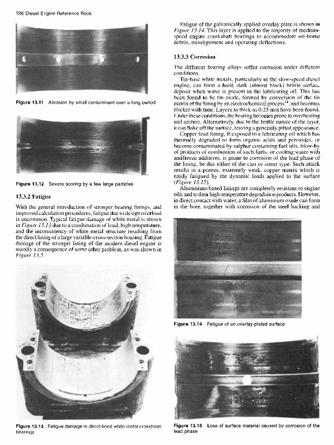
Figure 13.12 Severe scoring by a few large particles
13.3.2 Fatigue
With the general introduction of stronger bearing linings, andimproved calculation procedures, fatigue due to design overloadis uncommon. Typical fatigue damage of white metal is shownin Figure 13.13 due to a combination of load, high temperature,and the inconsistency of white metal structure resulting fromthe direct lining of a large variable-cross-section housing. Fatiguedamage of the stronger lining of the modern diesel engine isusually a consequence of some other problem, as was shown inFigure 13.5.
Fatigue of the galvanically applied overlay plate is shown inFigure 13.14. This layer is applied to the majority of medium-speed engine crankshaft bearings to accommodate oil-bornedebris, misalignment and operating deflections.
13.3.3 Corrosion
The different bearing alloys suffer corrosion under differentconditions.
Tin-base white metals, particularly in the slow-speed dieselengine, can form a hard, dark (almost black) brittle surfacedeposit when water is present in the lubricating oil. This hasbeen found to be tin oxide, formed by conversion of the tinmatrix of the lining by an electrochemical process14, and becomesthicker with time. Layers as thick as 0.25 mm have been found.Under these conditions, the bearing becomes prone to overheatingand seizure. Alternatively, due to the brittle nature of the layer,it can flake off the surface, leaving a generally pitted appearance.
Copper-lead lining, if exposed to a lubricating oil which hasthermally degraded to form organic acids and peroxides, orbecome contaminated by sulphur containing fuel oils, blow-byof products of combustion of such fuels, or cooling water withantifreeze additives, is prone to corrosion of the lead phase ofthe lining, be this either of the cast or sinter type. Such attackresults in a porous, extremely weak, copper matrix which iseasily fatigued by the dynamic loads applied to the surface(Figure 13.15).
Aluminium-based linings are completely resistant to engineoils, and to their high-temperature degradation products. However,in direct contact with water, a film of aluminium oxide can formin the bore, together with corrosion of the steel backing and
Figure 13.11 Abrasion by small contaminant over a long period
Figure 13.13 Fatigue damage in direct-lined white metal crossheadbearings
Figure 13.14 Fatigue of an overlay-plated surface
Figure 13.15 Loss of surface material caused by corrosion of thelead phase

possible lifting of the lining material, although in an oil environ-ment in an engine, this is virtually impossible.
13.3.4 Wiping
This type of damage (Figure 13.16} can occur with any liningmaterial, and is caused by insufficient lubricating and coolingoil on the bearing surface. This results in overheating andeventually melting of the lowest melting-point phase of thelining alloy. Potential causes of insufficient oil on the bearingsurface include inadequate generated oil film thickness,insufficient clearance, housing distortion, restriction in oil supplysystem, excessively worn bearings in other locations andinadequate oil pump capacity.
13.3.5 Cavitation
Cavitation erosion damage to bearing surfaces is a form ofmicro fatigue cracking, initiated by the collapse of vapour cavities,and is thoroughly discussed in Reference 12. Typical damage toa large end bearing is shown in Figure 13.17 and to a mainbearing in Figure 13.18.
13.3.6 Fretting
Figure 13.19 shows a severe case of fretting of a bearing due toinsufficient contact pressure, local welding and tearing havingtaken place between the bearing back and housing bore, resultingin transfer of metal from one to the other. Where fretting of thejoint faces of the bearing occurs, as shown in Figurel3.20, thisusually implies inadequate joint face clamping force. Frettingof the housing joints can also be expected under these conditions.
Before fitting new bearings where fretting has occurred, alltrace of fretting build-up in the housing must be removed toavoid premature catastrophic damage of the new bearing.
13.3.7 Design faults
Major design faults will not generally be evident in productionengines because they would have been found out very quicklyduring pre-production development testing. Some faults however,do not necessarily cause problems, but require certain otherconditions to exist also. An example of this would be blindlocation features, such as a dowel fitting in a hole in the bearingback. If positioned away from the heaviest loaded region ofthe bearing, this would not cause problems, unless duringassembly or re-fitting the dowel was not located correctly in thehole.
A bearing load diagram which results in an almost pure rotatingload pattern, i.e. where the load vector on the bearing surfacetravels at approximately shaft speed, can result in wiping andoverheating even though the theoretical oil film thickness is
Figure 13.16 Wiping damage
Figure 13.17 Cavitation erosion of a large end bearing
Figure 13.18 Cavitation erosion of a main bearing
Figure 13.19 Fretting of a bearing back due to insufficient contactpressure
Figure 13.20 Fretting of a bearing joint face due to inadequate boltload
greater on that bearing than on others in the same engine. Sucha condition is more likely to exist in an engine running on verylight load and full speed. The solution is to fit larger balanceweights to counteract the inertia forces of the crankshaft andconnecting rods. Adverse load patterns can be further aggravatedby incorrect positioning of oil holes in journal surfaces, anddamage due to this cause is typified by Figure 13.21.
13.3.8 Incorrect assembly
The commonest causes of incorrect assembly are associatedwith locating devices. Incorrect positioning will mean that oilfeed connections are misplaced and can block off the oil feed.Incorrect location of a tang into its recess means that the bearingback will not be in contact with the housing, and the clearancebetween the bearing bore and the crankshaft can be lost, resultingin local overheating of the bearing surface, and possibly seizure.
Having located the bearing correctly into its housing, caremust be taken to ensure that the housing bolts are correctlytensioned. Insufficient bolt load due to incorrect tightening canresult in the damage shown in Figure 13.20 and also excessivedynamic stressing of the bolts and ultimate fatigue fracture. Thebolts should also be tensioned in the prescribed sequence givenin the engine manual. Failure to follow the same sequence mayresult in a modified bore shape and unsatisfactory bearingperformance.
13.3.9 Environmental factors
13.3.9.1 Electrical discharge
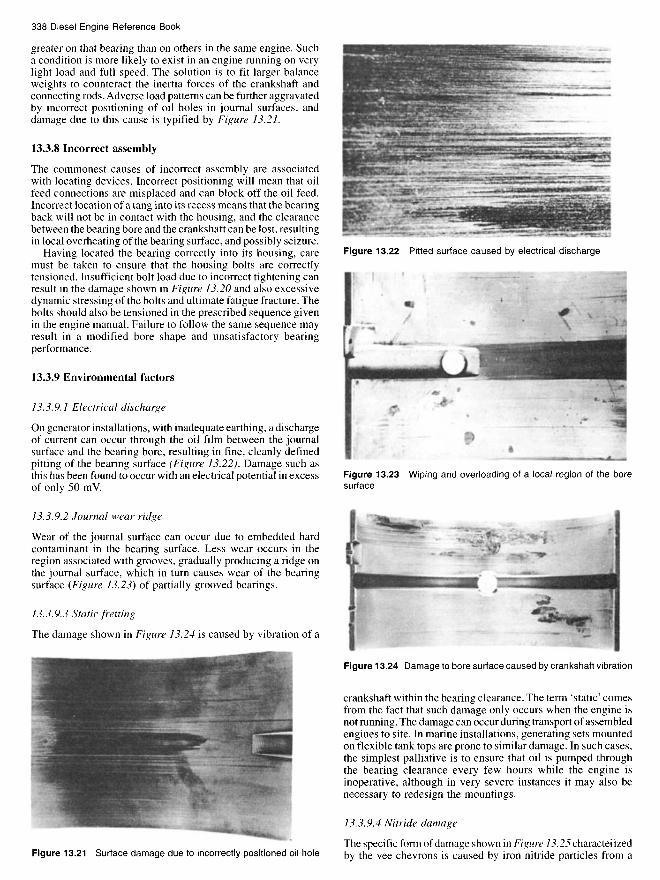
On generator installations, with inadequate earthing, a dischargeof current can occur through the oil film between the journalsurface and the bearing bore, resulting in fine, cleanly definedpitting of the bearing surface (Figure 13.22). Damage such asthis has been found to occur with an electrical potential in excessof only 50 mV.
13.3.9.2 Journal wear ridge
Wear of the journal surface can occur due to embedded hardcontaminant in the bearing surface. Less wear occurs in theregion associated with grooves, gradually producing a ridge onthe journal surface, which in turn causes wear of the bearingsurface (Figure 13.23) of partially grooved bearings.
13.3.9.3 Static fretting
The damage shown in Figure 13.24 is caused by vibration of a
Figure 13.24 Damage to bore surface caused by crankshaft vibration
crankshaft within the bearing clearance. The term 'static' comesfrom the fact that such damage only occurs when the engine isnot running. The damage can occur during transport of assembledengines to site. In marine installations, generating sets mountedon flexible tank tops are prone to similar damage. In such cases,the simplest palliative is to ensure that oil is pumped throughthe bearing clearance every few hours while the engine isinoperative, although in very severe instances it may also benecessary to redesign the mountings.
13.3.9.4 Nitride damage
The specific form of damage shown in Figure 13.25 characterizedby the vee chevrons is caused by iron nitride particles from aFigure 13.21 Surface damage due to incorrectly positioned oil hole
Figure 13.22 Pitted surface caused by electrical discharge
Figure 13.23 Wiping and overloading of a local region of the boresurface
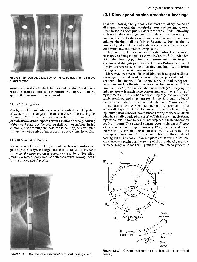
Figure 13.25 Damage caused by iron nitride particles from a nitridedjournal surface
nitride-hardened shaft which has not had the thin friable layerground off from the surface. To be sure of avoiding such damage,up to 0.02 mm needs to be removed.
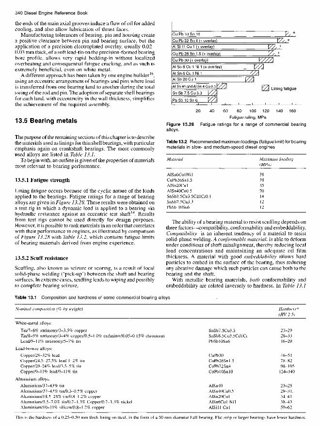
13.3.9.5 Misalignment
Misalignment through whatever cause is typified by a 'D' patternof wear, with the longest side on one end of the bearing, asFigure 13.26. Causes can be taper in the bearing housing orjournal surface, debris trapped between shell and housing, bruisingof the steel backing of the bearing shell or housing bore duringassembly, taper through the bore of the bearing, or a variationin alignment of a series of main bearing bores along the engine.
13.3.10 Geometric factors
Severe wear of localized regions of the bearing surface aregenerally caused by specific geometric inaccuracies. Heavy wearin the axial centre region is usually caused by a 'barrelled'journal, whereas heavy wear at both ends of the bearing resultsfrom an 'hour glass' profile.
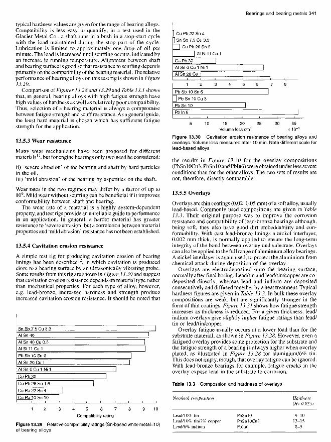
13.4 Slow-speed engine crosshead bearings
Thin shell bearings for probably the most arduously loaded ofall engine bearings, the two-stroke crosshead assembly, weretested by the major engine builders in the early 1960s. Followingsuch trials, they were gradually introduced into general pro-duction, and as loadings and conditions became even morearduous, the thin shell pre-finished bearing has become almostuniversally adopted in crossheads, and in several instances, inthe bottom end and main bearings also.
The basic problem encountered in direct-lined white metalbearings was lining fatigue (as shown in Figure 13.13). Adoptionof thin shell bearings permitted an improvement in metallurgicalstructure and strength, particularly at the steel/white-metal bondline by the use of centrifugal casting and improved uniformcooling of the constant cross-section.
Moreover, once the pre-finished thin shell is adopted, it allowsadvantage to be taken of the better fatigue properties of thestronger lining materials. One engine range has had 40 per centtin-aluminium-lined bearings incorporated from inception15. Thethin shell bearing has other inherent advantages. Carrying ofonboard spares is much more convenient, as is the re-fitting ofreplacements. Spares, when required urgently, are much moreeasily freighted and ship turn-round time is greatly reducedcompared with that for the assembly shown in Figure 13.13.
The bearing geometry can be much more closely controlledas a result of specialist manufacture and absence of hand fitting.Optimum performance of the crosshead bearing has been obtainedwith the so-called bedded-are profile. This is a machinable form,repeatable within fine tolerance, that replaces the hand-scrapedbedded-in form. The general configuration is shown in Figure13.27. Over an arc of approximately 120°, symmetrical aboutthe vertical centre line, the radial clearance between pin andbearing is almost zero. This is optimum because the crossheadbearing relies basically upon a squeeze film for lubrication.Axial grooves pitched at the swing of the crosshead pin allowoil to be swept onto the bearing surface. Small bleed grooves at
Figure 13.26 Surface wear associated with shaft misalignmentFigure 13.27 General configuration of a 'bedded arc' crossheadbearing
Wallthickness
LiningSteel Oil supply
hole
Bleedgroove
the ends of the main axial grooves induce a flow of oil for addedcooling, and also allow lubrication of thrust faces.
Manufacturing tolerances of bearing, pin and housing createa positive clearance between pin and bearing surface, but theapplication of a precision electroplated overlay, usually 0.02-0.03 mm thick, of a soft lead-tin on the precision-formed bearingbore profile, allows very rapid bedding-in without localizedoverheating and consequential fatigue cracking, and as such isextremely beneficial, even on white metal.
A different approach has been taken by one engine builder16,using an eccentric arrangement of bearings and pins where loadis transferred from one bearing land to another during the totalswing of the rod and pin. The adoption of separate shell bearingsfor each land, with eccentricity in the wall thickness, simplifiesthe achievement of the required assembly.
13.5 Bearing metals
The purpose of the remaining sections of this chapter is to describethe materials used as linings for thin shell bearings, with particularemphasis again on crankshaft bearings. The most commonlyused alloys are listed in Table 13.1.
To begin with, an outline is given of the properties of materialsmost relevant to bearing performance.
13.5.1 Fatigue strength
Lining fatigue occurs because of the cyclic nature of the loadsapplied to the bearings. Fatigue ratings for a range of bearingalloys are given in Figure 13.28. These results were obtained ona test rig in which a dynamic load is applied to a bearing viahydraulic resistance against an eccentric test shaft14. Resultsfrom test rigs cannot be used directly for design purposes.However, it is possible to rank materials in an order that correlateswith their performance in engines, as illustrated by comparisonof Figure 13.28 with Table 13.2, which contains fatigue limitsof bearing materials derived from engine experience.
13.5.2 Scuff resistance
Scuffing, also known as seizure or scoring, is a result of localsolid-phase welding ('pick-up') between the shaft and bearingsurfaces. In extreme cases, scuffing leads to wiping and possiblyto complete bearing seizure.
Fatigue rating, MPa
Figure 13.28 Fatigue ratings for a range of commercial bearingalloys.
Table 13.2 Recommended maximum loadings (fatigue limit) for bearingmaterials in slow- and medium-speed diesel engines
The ability of a bearing material to resist scuffing depends onthree factors—compatibility, conformability and embeddability.Compatibility is an inherent tendency of a material to resistsolid-phase welding. A conformable material, is able to deformunder conditions of shaft misalignment, thereby reducing localload concentrations and maintaining an adequate oil filmthickness. A material with good embeddability allows hardparticles to embed in the surface of the bearing, thus reducingany abrasive damage which such particles can cause both to thebearing and the shaft.
With metallic bearing materials, both conformability andembeddability are related inversely to hardness. In Table 13.1
Material
AlSn6CulNilCuPb26Snl.5AlSn20CulAlSn40Cu0.5SnSb8.5Cu3.5CdlCr0.1SnSb7.5Cu3.3PbSb 10Sn6
Maximum loading(MPa)
38383520141212
Table 13.1 Composition and hardness of some commercial bearing alloys
Nominal composition (% by weight)
White-metal alloys:
Tin/7-8% antimony/3-3.5% copperTin/8-9% antimony/3-4% copper/0.5-1.0% cadmium/0.05-0.15% chromiumLead/9-11% antimony/5-7% tin
Lead-bronze alloys:
Copper/28-32% leadCopper/24.5-27.5% lead 1-2% tinCopper/20-24% lead/3.5-5% tinCopper/9-11% lead/9-11% tin
Aluminium alloys:
Aluminium/37-43% tinAluminium/37-43% tin/0.3-0.5% copperAluminium/18.5-24% tin/0.8-1.2% copperAluminium/5.5-7.0% tin/0.7-1.3% Copper/0.7-1.3% nickelAluminium/10-11% silicon/0.8-1.2% copper
SnSb7.5Cu3.3SnSb8.5Cu3.5CdlCrPbSblOSn6
CuPb30CuPb26Snl.5CuPb22Sn4CuPbI OSn 10
AlSn40AlSn40Cu0.5AlSn20CulAlSn6Cul NilAlSiIl CuI
Hardness*(HV 2.5)
27-2928-3316-20
46-5178-8298-105
124-140
23-2529-31.34-4138-4359-62
This is the hardness of a 0.25-0.50 mm thick lining on steel, in the form of a 50 mm diameter half-bearing. Flat strip or larger bearings have lower hardness.
Lining fatigue
overlay
overlay
overlay
overlay
overlay
typical hardness values are given for the range of bearing alloys.Compatibility is less easy to quantify; in a test used in theGlacier Metal Co., a shaft runs in a bush in a stop-start cyclewith the load maintained during the stop part of the cycle.Lubrication is limited to approximately one drop of oil perminute. The load is increased until scuffing occurs, indicated byan increase in running temperature. Alignment between shaftand bearing surface is good so that resistance to scuffing dependsprimarily on the compatibility of the bearing material. The relativeperformance of bearing alloys on this test rig is shown in Figure13.29.
Comparison of Figures 13.28 and 13.29 and Table 13.1 showsthat, in general, bearing alloys with high fatigue strength havehigh values of hardness as well as relatively poor compatibility.Thus, selection of a bearing material is always a compromisebetween fatigue strength and scuff resistance. As a general guide,the least hard material is chosen which has sufficient fatiguestrength for the application.
13.5.3 Wear resistance
Many wear mechanisms have been proposed for differentmaterials17, but for engine bearings only two need be considered:
(i) 'severe abrasion' of the bearing and shaft by hard particlesin the oil,(ii) 'mild abrasion' of the bearing by asperities on the shaft.
Wear rates in the two regimes may differ by a factor of up to106. Mild wear without scuffing can be beneficial if it improvesconformability between shaft and bearing.
The wear rate of a material is a highly system-dependentproperty, and test rigs provide an unreliable guide to performancein an application. In general, a harder material has greaterresistance to 'severe abrasion' but a correlation between materialproperties and 'mild abrasion' resistance has not been established.
13.5.4 Cavitation erosion resistance
A simple test rig for producing cavitation erosion of bearinglinings has been described12, in which cavitation is producedclose to a bearing surface by an ultrasonically vibrating probe.Some results from this rig are shown in Figure 13.30 and suggestthat cavitation erosion resistance depends on material type ratherthan mechanical properties. For each type of alloy, however,e.g. lead-bronze, increased hardness and strength produceincreased cavitation erosion resistance. It should be noted that
Volume loss cm3 x 10 3
Figure 13.30 Cavitation erosion resistance of bearing alloys andoverlays. Volume loss measured after 10 min. Note different scale forlead-based alloys
the results in Figure 13.30 for the overlay compositions(PbSn 1 OCuS, PbSn 10 and Pbln6) were obtained under less severeconditions than for the other alloys. The two sets of results arenot, therefore, directly comparable.
13.5.5 Overlays
Overlays are thin coatings (0.02-0.05 mm) of a soft alloy, usuallylead-based. Commonly used compositions are given in Table13.3. Their original purpose was to improve the corrosionresistance and compatibility of lead-bronze bearings although,being soft, they also have good dirt embeddability and con-formability. With cast lead-bronze linings a nickel interlayer,0.002 mm thick, is normally applied to ensure the long-termintegrity of the bond between overlay and substrate. Overlayscan also be applied to the full range of aluminium alloy bearings.A nickel interlayer is again used, to protect the aluminium fromchemical attack during deposition of the overlay.
Overlays are electrodeposited onto the bearing surface,normally after final boring. Lead/tin and lead/tin/copper are co-deposited directly, whereas lead and indium are depositedconsecutively and diffused together by a heat treatment. Typicalhardness figures are given in Table 13.3. In bulk these overlaycompositions are weak, but are significantly stronger in theform of thin coatings. Figure 13.31 shows how fatigue strengthincreases as thickness is reduced. For a given thickness, lead/indium overlays give slightly higher fatigue ratings than lead/tin or lead/tin/copper.
Overlay fatigue usually occurs at a lower load than for thesubstrate material, as shown in Figure 13.28. However, even afatigued overlay provides some protection for the substrate andthe fatigue strength of a bearing is always higher when overlayplated, as illustrated in Figure 13.28 for aluminium/6% tin.This does not imply, though, that overlay fatigue can be ignored.With lead-bronze bearings for example, fatigue cracks in theoverlay expose lead in the substrate to corrosion.
Table 13.3 Composition and hardness of overlays
Compatibility rating
Figure 13.29 Relative compatibility ratings (Sn-based white metal=10)of bearing alloys
Nominal composition
Lead/ 10% tinLead/ 10% tin/3% copperLead/6% indium
PbSnIOPbSnIOCuSPbln6
Hardness(Hv 0.025)
9-1012-158-9

Thickness mm
Figure 13.31 Fatigue-strength/thickness relationship for overlays
Relative wear resistance is demonstrated by measurementsobtained using the dynamically loaded bearing test rig, and resultsare shown in Figure 13,32, Lead/tin/copper has a higher wearresistance than lead/tin, which is in turn superior to lead/indium.These results concur with those reported by Schaefer19. Therelatively poor wear resistance of lead/indium negates to someextent its high fatigue rating, since for a given wear life athicker overlay is required which leads to a lower fatigue strength.
Relative cavitation erosion rates are given in Figure 13.30.Lead/tin/copper has the highest resistance to cavitation, followedby lead/tin.
Tin or indium is necessary to improve corrosion resistance ofthe lead. The minimum levels required for adequate corrosionresistance are 3 per cent tin and 5 per cent indium20. Althoughthese levels are below those in the as-plated overlays, in service,tin and indium are lost by diffusion into the substrate18. Theresult is formation of intermetallic compounds with copper ornickel in the substrate or interlayer2', and corrosion of the overlayif the tin or indium level falls below the safety limit. Loss of tinis demonstrated by results shown in Figure 13.33, which wereobtained by heating sintered copper-lead bearings plated withlead/10% tin. It is sometimes claimed that a nickel interlayereliminates tin loss. However, this is not so, as shown in Figure13.33, although the rate of loss of tin is significantly reduced bythe presence of a nickel interlayer. Increasing the tin content ofthe overlay is not a complete solution to the tin diffusion problem,since the rate of diffusion is correspondingly increased.
Lead/tin/copper overlays are more corrosion resistant thanlead/tin, possibly because the rate of tin loss is lower with lead/tin/copper as a result of the formation of copper-tin compounds
Time at 10O0C h
Figure 13.33 Diffusion of Sn from Pb/Sn overlays on Cu/Pb with andwithout Ni barrier
within the overlay. Thus, the combination of high wear resistance,cavitation erosion resistance and corrosion resistance makeslead/tin/copper the preferred overlay for the modern highly ratedmedium-speed diesel engine, particularly when these operateon residual fuels.
13.5.6 White metals
Tin-based white metals are alloys of tin, antimony and copper,the most commonly used composition being tin/7.5% antimony/3.3% copper. The metallurgical structure (Figure 13.34) consistsof a tin-antimony matrix which is strengthened by needles ofcopper-tin compound.
The effects of composition and method of manufacture onthe mechanical and bearing properties of white metals havebeen described in detail by Pratt14. The effect of cooling conditionsduring production of bearing linings, referred to earlier, isdemonstrated by the results in Figure 13.35. Rapidly quenchedmaterial, obtained during production of thin shell bearings, hasa finer copper-tin compound distribution and a higher fatiguestrength than slow-cooled linings obtained when white metal iscast directly into large bearing structures.
The fatigue strength of the basic white metal composition
Figure 13.32 Comparative wear resistance for overlaysFigure 13.34 Typical structure of SnSb7.5Cu3.3, Showing star-shapedCu-Sn needles in Sn-Sb matrix
MPaon load
Wei
ght
loss
, g
Ni barrier
Ni barrier
Fatig
ue s
tren
gth
MP
a
Tin
con
tent
wei
ght %
Fatigue rating MPa
Figure 13.35 Effect of casting method and composition on fatiguestrength of Sn-based white metals
can be increased by adding cadmium, which goes into solutionin the matrix, and by adding trace quantities (0.1 per cent) ofchromium, which refines the distribution of the copper-tincompound. By this means, it is possible to produce commerciallya slow-cooled white-metal-lined bearing with a fatigue strengthas high as a rapidly cooled or quenched lining (Figure 13.35).
Conformability and embeddability of tin-based white metalsare very good, as would be expected for a material of low hardness.Corrosion resistance is good, except when the lubricating oil iscontaminated by water as described earlier. However, theoutstanding characteristic of tin-based white metal is itscompatibility, scuffing in service being virtually unknown. Inconditions of oil starvation linings suffer wiping rather thanscuffing and the wiped surfaces are capable of continuedoperation, which is not the case with most other bearing alloys.
Lead-based white metals are basically alloys of lead, tin andantimony, containing 6-12 per cent tin and 10-15 per centantimony. The structure of the 10 per cent antimony/6 per centtin composition consists of a single-phase lead-tin-antimonymatrix. At higher antimony contents, tin-antimony cuboids areformed. Another version contains 15 per cent antimony and 1per cent arsenic, the structure in this case being a fine antimony-arsenic precipitate, in a lead-antimony matrix.
Cooling conditions during bearing manufacture affectmechanical properties similarly to tin-based white metal, althoughrapidly cooled lead-based linings must be annealed to provideadequate ductility. Likewise, minor additions of certain metals—arsenic, copper, cadmium or nickel—can increase the fatiguestrength of a slow-cooled lining by refining the alloy structure.
In comparison with tin-based white metals, the lead-basedalloys are softer (Table 13.1} and hence have even betterconformability and dirt embeddability. Fatigue strength is similar(Figure 13.28). Tin and antimony contents are generally highenough to avoid corrosion problems in most applications.Compatibility, as assessed on the stop-start test rig describedabove, is not as good as tin-based white metal (Figure 13.29}although in service, scuffing of lead-based white metal is generallynot a problem. Wear and cavitation erosion resistance of thelead-based alloys are, however, inferior.
White metals were the first alloys developed specifically forplain bearings. Although their fatigue strength is relatively low,they are still widely used on account of their surface properties.Because of the rather better corrosion and scuff resistance oftin-based white metal, it is preferred to lead-based alloys incertain critical applications, e.g. crosshead bearings. For generalapplications, lead-based white metal bearings are significantlycheaper than their tin-based equivalents, but even so, the tin-based alloys are, by tradition, used more widely.
13.5.7 Copper-lead and lead-bronze alloys
Historically, lead-bronze bearing linings were introduced whenfatigue of white metal became a serious problem, as a result of
increased engine ratings. Modern thin shell bearings are madeeither by casting on to steel strip or by a sinter route, in whichpre-alloyed powder is applied to steel and consolidated bysintering and rolling. All of the lead-bronze alloys in Table 13.1can be made into bearings by either method; copper-leadlinings with 30 per cent or more lead are made only by the sinterroute.
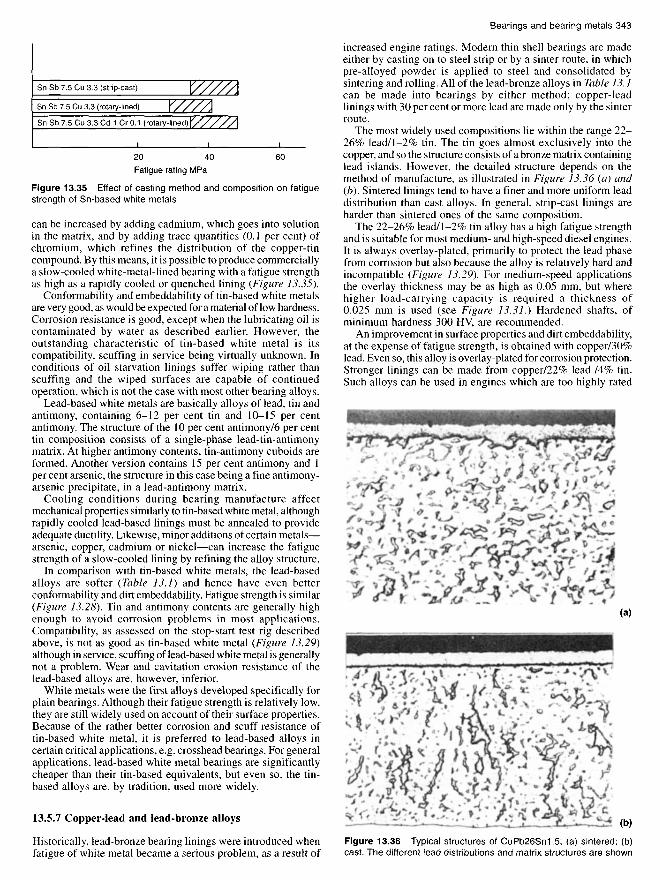
The most widely used compositions lie within the range 22-26% lead/1-2% tin. The tin goes almost exclusively into thecopper, and so the structure consists of a bronze matrix containinglead islands. However, the detailed structure depends on themethod of manufacture, as illustrated in Figure 13.36 (a) and(b). Sintered linings tend to have a finer and more uniform leaddistribution than cast alloys. In general, strip-cast linings areharder than sintered ones of the same composition.
The 22-26% lead/1-2% tin alloy has a high fatigue strengthand is suitable for most medium- and high-speed diesel engines.It is always overlay-plated, primarily to protect the lead phasefrom corrosion but also because the alloy is relatively hard andincompatible (Figure 13.29}. For medium-speed applicationsthe overlay thickness may be as high as 0.05 mm, but wherehigher load-carrying capacity is required a thickness of0.025 mm is used (see Figure 13.31.} Hardened shafts, ofminimum hardness 300 HV, are recommended.
An improvement in surface properties and dirt embeddability,at the expense of fatigue strength, is obtained with copper/30%lead. Even so, this alloy is overlay-plated for corrosion protection.Stronger linings can be made from copper/22% lead /4% tin.Such alloys can be used in engines which are too highly rated
Figure 13.36 Typical structures of CuPb26Sn1.5; (a) sintered; (b)cast. The different lead distributions and matrix structures are shown
(strip-cast)
(rotary-lined)
(rotary-lined)

for the 26% lead/1.5% tin alloy; a thin overlay and a hardenedshaft are required.
The copper/10% lead/10% tin alloy is very strong, but is toohard and prone to scuffing to be used as a crankshaft bearing.However, it is widely used for small end bushes, which are veryhighly loaded. In order to avoid scuffing, a hardened gudgeonpin (700 HV) is used, with a very fine surface finish.
13.5.8 Aluminium-tin alloys
The major impetus for the development of aluminium-tin bearingswas their superior corrosion resistance relative to lead-bronze.Four aluminium-tin alloys are used in diesel engines, and theirnominal compositions are given in Table 13.1. Bearings aremade by roll bonding the alloy to steel strip via an interlayer(for aluminium-tin alloys) which is usually aluminium.
Aluminium/6% tin is a long-established bearing material22,developed originally for cast bearings. Copper and nickel areadded to increase strength; copper is a solution hardener and thenickel forms a fine dispersion of nickel-aluminium compounds,as shown in Figure 13.37 (a}.
Fatigue strength is slightly lower than that of the lead-bronzes(Figure 13.28), but is more than adequate for most engineapplications. Compatibility is better (Figure 13.29), but the alloyis relatively hard and so is normally overlay-plated. Overlaythickness is normally in the range 0.02-0.05 mm, and shaftshardened to 250-300 HV are recommended.
Aluminium/20% tin with a 'reticular' tin structure wasdeveloped as a more compatible version of the 6% tin alloy. The
structure (Figure 13.37 (b)} consists of an aluminium/1% coppermatrix containing an interconnecting network of tin. This structureis essential if the alloy is to have adequate high-temperaturestrength, and is obtained by controlled cold working and heattreatment of the as-cast alloy. According to results from thestop/start test rig (Figure 13.29), the compatibility of aluminium/20% tin is superior to the 6% tin alloy, and in practice it hasproved to be sufficiently scuff resistant to operate successfullywithout an overlay. Although its fatigue strength is marginallylower than aluminium/6% tin it is high enough to use withoutan overlay in the majority of high-speed engines; for medium-speed diesel engines it is usually overlay-plated and run againsta shaft of minimum hardness 250 HV.
High-tin aluminium alloys, containing 40 per cent or moretin, were developed as a higher strength replacement for whitemetal in slow-speed diesel engines. Their use in such applicationswas not possible until thin shell bearings were adopted, becausecast-in linings cannot be produced with aluminium alloys. Twoforms are available, aluminium/40% tin which is used unplated,and, forcrosshead applications, overlay-plated aluminium/40%tin/0.5% copper.
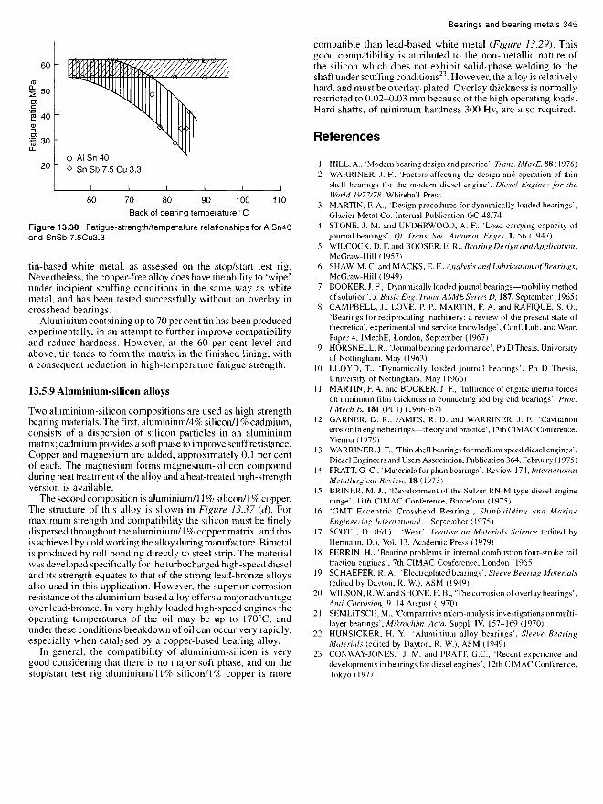
The 'reticular' tin structure and continuous aluminium matrixare also present in these high-tin alloys (Figure 13.37 (c)). Asa result, aluminium/40% tin maintains its fatigue strength atelevated temperature, whereas white metal becomes significantlyweaker, as shown in Figure 13.38. At typical engine operatingtemperatures aluminium/40% tin is approximately 30% strongerthan white metal.
The compatibility of aluminium/40% tin is not as good as
Figure 13.37 Typical structures of (a) AISn6Cu1NM; (b) AISn20Cu1; (c) AISn40; (d) AISi11 Cu1
Back of bearing temperature 0C
Figure 13.38 Fatigue-strength/temperature relationships for AISn40and SnSb 7.5Cu3.3
tin-based white metal, as assessed on the stop/start test rig.Nevertheless, the copper-free alloy does have the ability to 'wipe'under incipient scuffing conditions in the same way as whitemetal, and has been tested successfully without an overlay incrosshead bearings.
Aluminium containing up to 70 per cent tin has been producedexperimentally, in an attempt to further improve compatibilityand reduce hardness. However, at the 60 per cent level andabove, tin tends to form the matrix in the finished lining, witha consequent reduction in high-temperature fatigue strength.
13.5.9 Aluminium-silicon alloys
Two aluminium-silicon compositions are used as high-strengthbearing materials. The first, aluminium/4% silicon/1 % cadmium,consists of a dispersion of silicon particles in an aluminiummatrix; cadmium provides a soft phase to improve scuff resistance.Copper and magnesium are added, approximately 0.1 per centof each. The magnesium forms magnesium-silicon compoundduring heat treatment of the alloy and a heat-treated high-strengthversion is available.
The second composition is aluminium/11 % silicon/1 % copper.The structure of this alloy is shown in Figure 13.37 (d]. Formaximum strength and compatibility the silicon must be finelydispersed throughout the aluminium/1 % copper matrix, and thisis achieved by cold working the alloy during manufacture. Bimetalis produced by roll bonding directly to steel strip. The materialwas developed specifically for the turbocharged high-speed dieseland its strength equates to that of the strong lead-bronze alloysalso used in this application. However, the superior corrosionresistance of the aluminium-based alloy offers a major advantageover lead-bronze. In very highly loaded high-speed engines theoperating temperatures of the oil may be up to 17O0C, andunder these conditions breakdown of oil can occur very rapidly,especially when catalysed by a copper-based bearing alloy.
In general, the compatibility of aluminium-silicon is verygood considering that there is no major soft phase, and on thestop/start test rig aluminium/11% silicon/1% copper is more
compatible than lead-based white metal (Figure 13.29). Thisgood compatibility is attributed to the non-metallic nature ofthe silicon which does not exhibit solid-phase welding to theshaft under scuffing conditions23. However, the alloy is relativelyhard, and must be overlay-plated. Overlay thickness is normallyrestricted to 0.02-0.03 mm because of the high operating loads.Hard shafts, of minimum hardness 300 Hv, are also required.
References
1 HILL, A., 'Modern bearing design and practice', Trans. IMarE, 88(1976)2 WARRINER, J. F., 'Factors affecting the design and operation of thin
shell bearings for the modern diesel engine', Diesel Engines for theWorld 1977/78, Whitehall Press
3 MARTIN, F. A., 'Design procedures for dynamically loaded bearings',Glacier Metal Co. Internal Publication GC 48/74
4 STONE, J. M. and UNDERWOOD, A. F, 'Load carrying capacity ofjournal bearings', Qt. Trans. Soc. Automot. Engrs.,1, 56 (1947)
5 WILCOCK, D. F. and BOOSER, E. R., Bearing Design and Application,McGraw-Hill (1957)
6 SHAW, M. C. and MACKS, E. P., Analysis and Lubrication of Bearings,McGraw-Hill (1949)
7 BOOKER, J. F, 'Dynamically loaded journal bearings—mobility methodof solution', J. Basic Eng. Trans. ASME Series D, 187, September (1965)
8 CAMPBELL, J., LOVE, P. P., MARTIN, F. A. and RAFIQUE, S. O.,'Bearings for reciprocating machinery: a review of the present state oftheoretical, experimental and service knowledge', Conf. Lub. and Wear,Paper 4, IMechE, London, September (1967)
9 HORSNELL, R., 'Journal bearing performance', Ph D Thesis, Universityof Nottingham, May (1963)
10 LLOYD, T., 'Dynamically loaded journal bearings', Ph D Thesis,University of Nottingham, May (1966)
11 MARTIN, F. A. and BOOKER, J. F, 'Influence of engine inertia forceson minimum film thickness in connecting rod big end bearings', Proc.I Mech E, 181 (Pt 1) (1966-67)
12 GARNER, D. R., JAMES, R. D. and WARRINER, J. F., 'Cavitationerosion in engine bearings—theory and practice', 13th CIMAC Conference,Vienna (1979)
13 WARRINER, J. F, 'Thin shell bearings for medium speed diesel engines',Diesel Engineers and Users Association, Publication 364, February (1975)
14 PRATT, G. C., 'Materials for plain bearings', Review 174, InternationalMetallurgical Review, 18 (1973)
15 BRINER, M. J., 'Development of the Sulzer RN-M type diesel enginerange', 1 lth CIMAC Conference, Barcelona (1975)
16 'GMT Eccentric Crosshead Bearing' , Shipbuilding and MarineEngineering International , September (1975)
17 SCOTT, D. (Ed.), 'Wear', Treatise on Materials Science (edited byHermann, D.), Vol. 13, Academic Press (1979)
18 PERRIN, H., 'Bearing problems in internal combustion four-stroke railtraction engines', 7th CIMAC Conference, London (1965)
19 SCHAEFER, R. A., 'Electroplated bearings', Sleeve Bearing Materials(edited by Dayton, R. W.), ASM (1949)
20 WILSON5R. W. and SHONE, E. B., The corrosion of overlay bearings',Anti-Corrosion, 9-14 August (1970)
21 SEMLITSCH, M., 'Comparative micro-analysis investigations on multi-layer bearings', Mikrochim. Acta, Suppl. IV, 157-169 (1970)
22 HUNSICKER, H. Y., 'Aluminium alloy bearings', Sleeve BearingMaterials (edited by Dayton, R. W.), ASM (1949)
23 CONWAY-JONES, J. M. and PRATT, G.C., 'Recent experience anddevelopments in bearings for diesel engines', 12th CIMAC Conference,Tokyo (1977)
Fatig
ue r
atin
g M
Pa