journal of archaeological science sci... · archaeologists use the pointing device as a stylus to...
TRANSCRIPT

lable at ScienceDirect
Journal of Archaeological Science 36 (2009) 2415–2426
Contents lists avai
Journal of Archaeological Science
journal homepage: ht tp: / /www.elsevier .com/locate/ jas
A computerized system to determine the provenance of finds in archaeologicalsites using acoustic signals
A.R. Jimenez a,*, J.C. Prieto a, J.L. Ealo a,b, J. Guevara a, F. Seco a
a Instituto de Automatica Industrial, Consejo Superior de Investigaciones Cientıficas – CSIC, Ctra. Campo Real km 0.2 La Poveda, 28500 Arganda del Rey, Madrid, Spainb School of Mechanical Engineering, Universidad del Valle, Colombia
a r t i c l e i n f o
Article history:Received 11 January 2008Received in revised form16 December 2008Accepted 29 June 2009
Keywords:On-site artifact provenanceSpatial localizationComputers in archaeological excavations
* Corresponding author. Fax: þ34 91 871 70 50.E-mail address: [email protected] (A.R. JimeneURL: http://www.iai.csic.es/lopsi
0305-4403/$ – see front matter � 2009 Elsevier Ltd.doi:10.1016/j.jas.2009.06.027
a b s t r a c t
Some archaeological excavations require the accurate determination of the provenance of finds (three-dimensional location and orientation) for a subsequent spatial analysis. The traditional manualmeasurement using a grid reference is not a very efficient registration method. Some proposedcomputerized solutions based on total stations, photogrammetry and DGPS, are more effective but havesome limitations. This paper presents a new acoustic localization system (3D-LOCUS) for measuring thethree-dimensional position of finds in archaeological sites. The system can also be used for registeringthe size, shape and orientation of artifacts. 3D-LOCUS basically consists of a set of wireless rod-likepointing devices that are localized with a network of intelligent nodes installed above the excavation site.Archaeologists use the pointing device as a stylus to locate and outline the object under study. The maintechnological characteristics of the system are: omnidirectional wideband acoustic transducers, Bidi-rectional Time-Of-Arrival (BTOA) estimation, redundant ranging and robust trilateration. 3D-LOCUSachieves an accurate registration, even if used simultaneously to the digging labor, or in noisy orturbulent airflow conditions. We tested the system in the Gran Dolina archaeological site (Atapuerca,Spain). The typical location accuracy is below 10 mm in natural conditions, and the achieved resolution is5 mm, which allows us sketching objects with enough detail.
� 2009 Elsevier Ltd. All rights reserved.
1. Introduction
During the last decades, computers have played an importantrole in archaeology, mainly through the use of databases andstatistical tools (Doran and Hodson, 1975). Computerized systemshave been proposed (Dibble and McPherron, 1988) to assist thedifferent stages in archaeological field works: (1) computerizedartifact data acquisition, (2) integration of different types of datainto computer databases, and (3) data analysis and graphicalmanipulation. Current advances in information and communica-tion technologies have now the potential to be used in creating newarchaeological aids, for example, provenance tools for excavationsrequiring a high level of recorded detail.
Gran Dolina is one of those archaeological sites that requiresa detailed artifact provenance registration. This includes the exactthree-dimensional position, orientation and shape of every objectuncovered. Gran Dolina, a worldwide-recognized site by the
z).
All rights reserved.
discovery of fossils from Homo antecessor, is one of the cavesbelonging to the Atapuerca archaeological complex (Fernandez-Jalvo and Andrews, 1992). It is located in a region of karstic hills(1100 m high) in the north of Spain. In this site thousands of fossilsare discovered every year needing to be accurately registered.
The current procedure to get the provenance of finds in Ata-puerca is not satisfactory. Gran Dolina excavation site has a workingarea of 60 m2 and an intensive digging activity (Fig. 1). Using strings,the excavation area is partitioned into reference cells of one squaremeter each for measuring the XY coordinates of finds; a levelledlaser beam and a measuring rod are used for measuring theirvertical coordinates. After each artifact is manually registered forposition, orientation and size, the archaeologist writes this infor-mation in a PDA (Personal Digital Assistant), or alternatively ina notebook. The time needed for measurement and annotation issignificant, and therefore, the digging speed is quite slow (at thispace, excavation works are foreseen to last for 30 years or more). Inorder to improve the registration process at Atapuerca, we have beenlooking for new methodologies to register artifacts faster, accuratelyand efficiently.
Some modern methodologies have been proposed for automatedon-site artifact provenance registration, mainly: total stations,
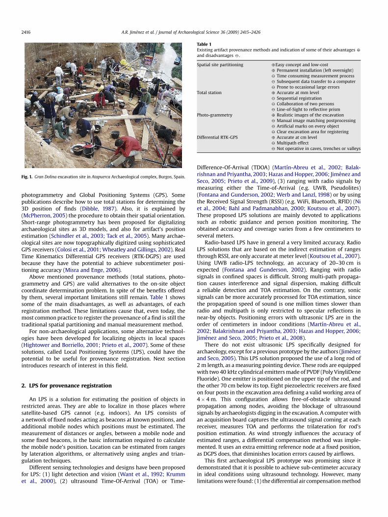
Fig. 1. Gran Dolina excavation site in Atapuerca Archaeological complex, Burgos, Spain.
Table 1Existing artifact provenance methods and indication of some of their advantages 4
and disadvantages 2.
Spatial site partitioning 4Easy concept and low-cost4 Permanent installation (left overnight)2 Time consuming measurement process2 Subsequent data transfer to a computer2 Prone to occasional large errors
Total station 4 Accurate at mm level2 Sequential registration2 Collaboration of two persons2 Line-of-Sight to reflective prism
Photo-grammetry 4 Realistic images of the excavation2 Manual image matching postprocessing2 Artificial marks on every object2 Clear excavation area for registering
Differential RTK-GPS 4 Accurate at cm level2 Multipath effect2 Not operative in caves, trenches or valleys
A.R. Jimenez et al. / Journal of Archaeological Science 36 (2009) 2415–24262416
photogrammetry and Global Positioning Systems (GPS). Somepublications describe how to use total stations for determining the3D position of finds (Dibble, 1987). Also, it is explained by(McPherron, 2005) the procedure to obtain their spatial orientation.Short-range photogrammetry has been proposed for digitalizingarchaeological sites as 3D models, and also for artifact’s positionestimation (Schindler et al., 2003; Tack et al., 2005). Many archae-ological sites are now topographically digitized using sophisticatedGPS receivers (Colosi et al., 2001; Wheatley and Gillings, 2002). RealTime Kinematics Differential GPS receivers (RTK-DGPS) are usedbecause they have the potential to achieve subcentimeter posi-tioning accuracy (Misra and Enge, 2006).
Above mentioned provenance methods (total stations, photo-grammetry and GPS) are valid alternatives to the on-site objectcoordinate determination problem. In spite of the benefits offeredby them, several important limitations still remain. Table 1 showssome of the main disadvantages, as well as advantages, of eachregistration method. These limitations cause that, even today, themost common practice to register the provenance of a find is still thetraditional spatial partitioning and manual measurement method.
For non-archaeological applications, some alternative technol-ogies have been developed for localizing objects in local spaces(Hightower and Borriello, 2001; Prieto et al., 2007). Some of thesesolutions, called Local Positioning Systems (LPS), could have thepotential to be useful for provenance registration. Next sectionintroduces research of interest in this field.
2. LPS for provenance registration
An LPS is a solution for estimating the position of objects inrestricted areas. They are able to localize in those places wheresatellite-based GPS cannot (e.g. indoors). An LPS consists ofa network of fixed nodes acting as beacons at known positions, andadditional mobile nodes which positions must be estimated. Themeasurement of distances or angles, between a mobile node andsome fixed beacons, is the basic information required to calculatethe mobile node’s position. Location can be estimated from rangesby lateration algorithms, or alternatively using angles and trian-gulation techniques.
Different sensing technologies and designs have been proposedfor LPS: (1) light detection and vision (Want et al., 1992; Krummet al., 2000), (2) ultrasound Time-Of-Arrival (TOA) or Time-
Difference-Of-Arrival (TDOA) (Martın-Abreu et al., 2002; Balak-rishnan and Priyantha, 2003; Hazas and Hopper, 2006; Jimenez andSeco, 2005; Prieto et al., 2009), (3) ranging with radio signals bymeasuring either the Time-of-Arrival (e.g. UWB, Pseudolites)(Fontana and Gunderson, 2002; Werb and Lanzl, 1998) or by usingthe Received Signal Strength (RSSI) (e.g. WiFi, Bluetooth, RFID) (Niet al., 2004; Bahl and Padmanabhan, 2000; Koutsou et al., 2007).These proposed LPS solutions are mainly devoted to applicationssuch as robotic guidance and person position monitoring. Theobtained accuracy and coverage varies from a few centimeters toseveral meters.
Radio-based LPS have in general a very limited accuracy. RadioLPS solutions that are based on the indirect estimation of rangesthrough RSSI, are only accurate at meter level (Koutsou et al., 2007).Using UWB radio-LPS technology, an accuracy of 20–30 cm isexpected (Fontana and Gunderson, 2002). Ranging with radiosignals in confined spaces is difficult. Strong multi-path propaga-tion causes interference and signal dispersion, making difficulta reliable detection and TOA estimation. On the contrary, sonicsignals can be more accurately processed for TOA estimation, sincethe propagation speed of sound is one million times slower thanradio and multipath is only restricted to specular reflections innear-by objects. Positioning errors with ultrasonic LPS are in theorder of centimeters in indoor conditions (Martın-Abreu et al.,2002; Balakrishnan and Priyantha, 2003; Hazas and Hopper, 2006;Jimenez and Seco, 2005; Prieto et al., 2008).
There do not exist ultrasonic LPS specifically designed forarchaeology, except for a previous prototype by the authors (Jimenezand Seco, 2005). This LPS solution proposed the use of a long rod of2 m length, as a measuring pointing device. These rods are equippedwith two 40 kHz cylindrical emitters made of PVDF (Poly VinyliDeneFluoride). One emitter is positioned on the upper tip of the rod, andthe other 70 cm below its top. Eight piezoelectric receivers are fixedon four posts in the excavation area defining a valid working area of4� 4 m. This configuration allows free-of-obstacle ultrasoundpropagation among nodes, avoiding the blockage of ultrasoundsignals by archaeologists digging in the excavation. A computer withan acquisition board captures the ultrasound signal coming at eachreceiver, measures TOA and performs the trilateration for rod’sposition estimation. As wind strongly influences the accuracy ofestimated ranges, a differential compensation method was imple-mented. It uses an extra emitting reference node at a fixed position,as DGPS does, that diminishes location errors caused by airflows.
This first archaeological LPS prototype was promising since itdemonstrated that it is possible to achieve sub-centimeter accuracyin ideal conditions using ultrasound technology. However, manylimitations were found: (1) the differential air compensation method
A.R. Jimenez et al. / Journal of Archaeological Science 36 (2009) 2415–2426 2417
was not effective enough since it is only valid for homogeneousairflow (i.e without turbulence), and it depends on the proximity ofthe pointing device to the reference node; (2) the limited bandwidthof transducers restricts the number of users (tools) operating at thesame time; (3) the system can only support 8 receivers (not scalable)and the location area is restricted to a square of 4� 4 m (poorcoverage); (4) the acoustic pattern of cylindrical transducer on therod forces the receiving nodes to be on posts close to the excavationsurface (intrusive system); additionally, (5) there is an excessivecabling among the PC and each node. These limitations encouragedus to design a new second LPS version for archaeology (3D-LOCUS),which is described in this paper.
The next section gives a thorough description of the new 3D-LOCUS LPS. Section 4 evaluates localization and sketching results inboth laboratory and Gran Dolina site conditions. Section 5 discussesthe main results found, and finally, the last section gives someconclusions.
3. 3D-LOCUS system description
3D-LOCUS is a new system for registering the three-dimensionallocation, shape and orientation of finds in archaeological digs. Itsdesign took into account the performance and operativenessexpected for most archaeological sites requiring a high level ofrecorded detail. Mainly those requirements are high accuracy, easeof use, and validity for different excavations. Our proposed solutioninherits some of the features of the first LPS (Jimenez and Seco,2005): long pointing devices and acoustic ranging. Additionally, 3D-LOCUS incorporates many new design improvements, e.g. trans-ducers having a wide bandwidth, bidirectional signal propagation,wireless pointing devices, multiuser operation, and robustness toairflows. The next subsections give more details on these topics.
3.1. Design concept and functional description
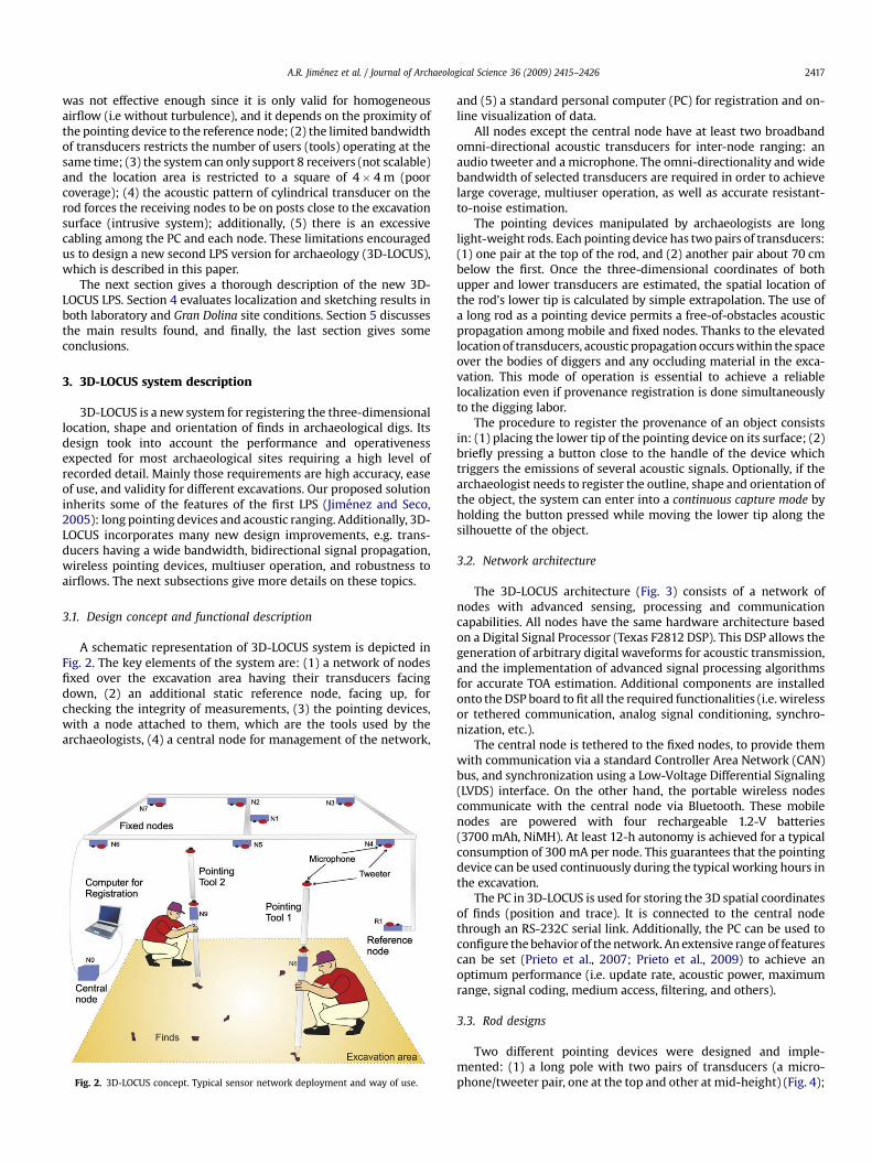
A schematic representation of 3D-LOCUS system is depicted inFig. 2. The key elements of the system are: (1) a network of nodesfixed over the excavation area having their transducers facingdown, (2) an additional static reference node, facing up, forchecking the integrity of measurements, (3) the pointing devices,with a node attached to them, which are the tools used by thearchaeologists, (4) a central node for management of the network,
Fig. 2. 3D-LOCUS concept. Typical sensor network deployment and way of use.
and (5) a standard personal computer (PC) for registration and on-line visualization of data.
All nodes except the central node have at least two broadbandomni-directional acoustic transducers for inter-node ranging: anaudio tweeter and a microphone. The omni-directionality and widebandwidth of selected transducers are required in order to achievelarge coverage, multiuser operation, as well as accurate resistant-to-noise estimation.
The pointing devices manipulated by archaeologists are longlight-weight rods. Each pointing device has two pairs of transducers:(1) one pair at the top of the rod, and (2) another pair about 70 cmbelow the first. Once the three-dimensional coordinates of bothupper and lower transducers are estimated, the spatial location ofthe rod’s lower tip is calculated by simple extrapolation. The use ofa long rod as a pointing device permits a free-of-obstacles acousticpropagation among mobile and fixed nodes. Thanks to the elevatedlocation of transducers, acoustic propagation occurs within the spaceover the bodies of diggers and any occluding material in the exca-vation. This mode of operation is essential to achieve a reliablelocalization even if provenance registration is done simultaneouslyto the digging labor.
The procedure to register the provenance of an object consistsin: (1) placing the lower tip of the pointing device on its surface; (2)briefly pressing a button close to the handle of the device whichtriggers the emissions of several acoustic signals. Optionally, if thearchaeologist needs to register the outline, shape and orientation ofthe object, the system can enter into a continuous capture mode byholding the button pressed while moving the lower tip along thesilhouette of the object.
3.2. Network architecture
The 3D-LOCUS architecture (Fig. 3) consists of a network ofnodes with advanced sensing, processing and communicationcapabilities. All nodes have the same hardware architecture basedon a Digital Signal Processor (Texas F2812 DSP). This DSP allows thegeneration of arbitrary digital waveforms for acoustic transmission,and the implementation of advanced signal processing algorithmsfor accurate TOA estimation. Additional components are installedonto the DSP board to fit all the required functionalities (i.e. wirelessor tethered communication, analog signal conditioning, synchro-nization, etc.).
The central node is tethered to the fixed nodes, to provide themwith communication via a standard Controller Area Network (CAN)bus, and synchronization using a Low-Voltage Differential Signaling(LVDS) interface. On the other hand, the portable wireless nodescommunicate with the central node via Bluetooth. These mobilenodes are powered with four rechargeable 1.2-V batteries(3700 mAh, NiMH). At least 12-h autonomy is achieved for a typicalconsumption of 300 mA per node. This guarantees that the pointingdevice can be used continuously during the typical working hours inthe excavation.
The PC in 3D-LOCUS is used for storing the 3D spatial coordinatesof finds (position and trace). It is connected to the central nodethrough an RS-232C serial link. Additionally, the PC can be used toconfigure the behavior of the network. An extensive range of featurescan be set (Prieto et al., 2007; Prieto et al., 2009) to achieve anoptimum performance (i.e. update rate, acoustic power, maximumrange, signal coding, medium access, filtering, and others).
3.3. Rod designs
Two different pointing devices were designed and imple-mented: (1) a long pole with two pairs of transducers (a micro-phone/tweeter pair, one at the top and other at mid-height) (Fig. 4);
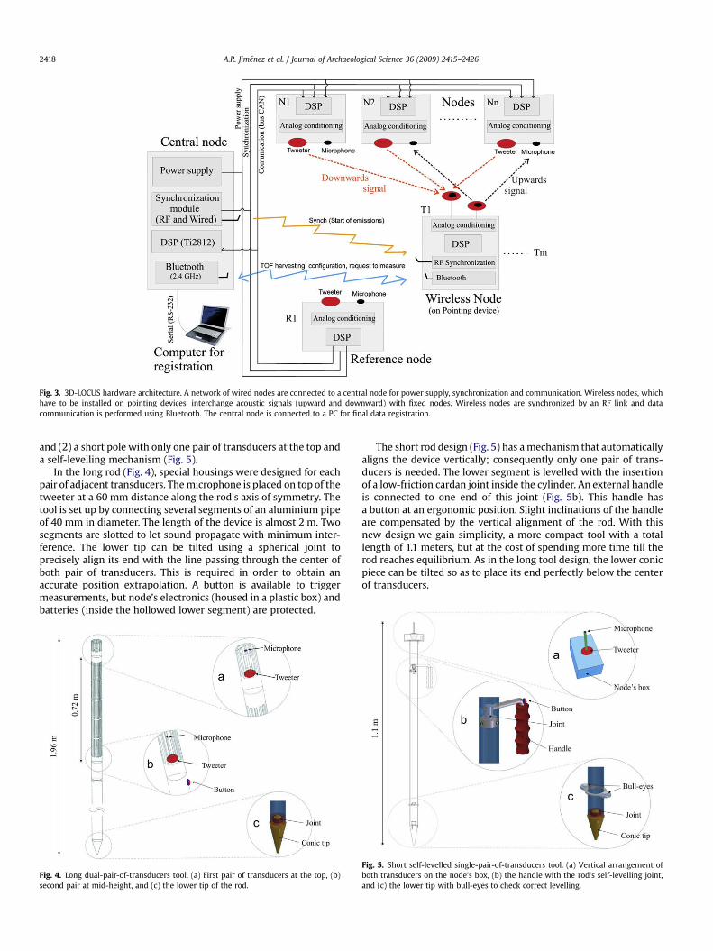
Fig. 3. 3D-LOCUS hardware architecture. A network of wired nodes are connected to a central node for power supply, synchronization and communication. Wireless nodes, whichhave to be installed on pointing devices, interchange acoustic signals (upward and downward) with fixed nodes. Wireless nodes are synchronized by an RF link and datacommunication is performed using Bluetooth. The central node is connected to a PC for final data registration.
A.R. Jimenez et al. / Journal of Archaeological Science 36 (2009) 2415–24262418
and (2) a short pole with only one pair of transducers at the top anda self-levelling mechanism (Fig. 5).
In the long rod (Fig. 4), special housings were designed for eachpair of adjacent transducers. The microphone is placed on top of thetweeter at a 60 mm distance along the rod’s axis of symmetry. Thetool is set up by connecting several segments of an aluminium pipeof 40 mm in diameter. The length of the device is almost 2 m. Twosegments are slotted to let sound propagate with minimum inter-ference. The lower tip can be tilted using a spherical joint toprecisely align its end with the line passing through the center ofboth pair of transducers. This is required in order to obtain anaccurate position extrapolation. A button is available to triggermeasurements, but node’s electronics (housed in a plastic box) andbatteries (inside the hollowed lower segment) are protected.
Fig. 4. Long dual-pair-of-transducers tool. (a) First pair of transducers at the top, (b)second pair at mid-height, and (c) the lower tip of the rod.
The short rod design (Fig. 5) has a mechanism that automaticallyaligns the device vertically; consequently only one pair of trans-ducers is needed. The lower segment is levelled with the insertionof a low-friction cardan joint inside the cylinder. An external handleis connected to one end of this joint (Fig. 5b). This handle hasa button at an ergonomic position. Slight inclinations of the handleare compensated by the vertical alignment of the rod. With thisnew design we gain simplicity, a more compact tool with a totallength of 1.1 meters, but at the cost of spending more time till therod reaches equilibrium. As in the long tool design, the lower conicpiece can be tilted so as to place its end perfectly below the centerof transducers.
Fig. 5. Short self-levelled single-pair-of-transducers tool. (a) Vertical arrangement ofboth transducers on the node’s box, (b) the handle with the rod’s self-levelling joint,and (c) the lower tip with bull-eyes to check correct levelling.

A.R. Jimenez et al. / Journal of Archaeological Science 36 (2009) 2415–2426 2419
For those experienced archaeologist who prefer to level theshort rod manually, bull’s eyes are installed at both sides of thecylinder (see Fig. 5c). This non-self-levelled mode of operation isvalid for single measurements but we believe it is not very appro-priate for continuous mode of operation since it requires a dynamicmanual levelling.
3.4. Acoustic transducers and signal processing
In order to cope with 3D-LOCUS requirements we decided to usebroadband and omnidirectional transducers, together with a spread-spectrum signal processing method that uses pseudo-random noise(PRN) digital codes. Since classical ultrasonic transducers do notcope with these features we decided to use acoustic transducersoperating mainly in the audible region.
As the emitter, we use the CP13 tweeter from Visaton. It hasa usable frequency band up to 25 kHz, and a wide emission patternthat is omnidirectional for audible frequencies. As the receiver, weuse the WM61 microphone from Panasonic, which has a goodsensitivity and an omnidirectional directivity at frequencies below42 kHz (Prieto et al., 2007). The diameter of the tweeter and themicrophone are 35 mm and 6 mm, respectively. Fig. 6 shows bothtransducers installed in one 3D-LOCUS node’s box.
In order to avoid audible signals which can disturb archaeolo-gists in the excavation area, emission frequencies were selectedevading the frequency band were humans are most sensitive (2–5 kHz). Emitted signals use a bandwidth between 5 and 25 kHz,which is large enough to provide accurate ranging and good noiseresistance. Signals are generated using a 15 kHz sinusoidal carriermodulated with PRN codes by Direct-Sequence Binary Phase ShiftKeying (DS-BPSK) (Oppenheim et al., 1999).
To unambiguously identify each node and to allow multi-useroperation, we use a unique Golay PRN codes in the signals generatedby every node (Popovic, 1999). Long PRN codes provide accurateranging but the detection capability can be degraded in turbulentairflow scenarios such as archaeological sites (Alvarez et al., 2006). APRN code length of 32 chips was used as a compromise betweenaccurate ranging and detection capability.
Cumulative XYZ error for
3.5. Node calibration for accurate ranging
If transducers are non-symmetric and the orientation betweennodes varies, the accuracy of the measured ranges could be
Fig. 6. Acoustic transducers (tweeter and microphone) installed in a 3D-LOCUS node.
deteriorated. Reliable ranging with independence of node’s orien-tation can be achieved if transducers are point-like or at least theybehave as having a virtual center of emission or reception. Ina previous work by the authors (Prieto et al., 2007), it was found thatboth tweeter and microphone behave as point-like transducers. Atotal ranging error of �1.5 mm was found for an angular variationbetween transducers of�90�. The virtual center of emission of CP13tweeter was found to be 4.2 mm ahead from the surface of the box(Fig. 6) along tweeter’s axis of revolution. The virtual center ofreception of Panasonic’s microphone is 0.4 mm ahead box’s surface.
A second important issue for accurate ranging is the determi-nation and compensation of any existing delay affecting TOF esti-mations. They can be caused by non-perfect RF synchronization,and also provoked by the joint transfer function of transducers andelectronics. As presented in (Prieto et al., 2007), these delays weredetermined accurately for 3D-LOCUS nodes, being 82.8 ms for RFsynchronization, and 128.6 ms for a joint transducer/electronicstransfer function.
3.6. Bidirectional and redundant positioning
One of the major limitations of acoustic LPS, when used inoutdoor sites, is the influence of wind on actual TOA. Wind fromemitter to receiver, or downstream, increases propagation speedand therefore measured TOA are shorter than in calm air orupstream. Ideally, the effect of airflows on measured TOA dependson wind intensity along the propagation axis, Val, and the actualrange, r, between nodes; as given by the following equationDt¼ rVal/Vs
2, where Vs is the speed of sound in calm air and Dt is thefinal error in TOA.
A solution to this airflow problem was proposed in the firstultrasonic LPS for archaeology (Jimenez and Seco, 2005) that con-sisted in adding a reference node for estimating the three compo-nents of the speed of air. By including this anemometry informationin the positioning algorithms, localization estimation was morereliable. However this procedure is only valid in the ideal case ofuniform airflow. In a realistic terrain, like an archaeological site,airflows are not uniform but turbulent.
The approach in 3D-LOCUS consists in transmitting acousticsignals in both directions between every pair of nodes involved inthe trilateration. In a first phase, nodes on the pointing device are
0 2 4 6 8 10 120
10
20
30
40
50
60
70
80
90
100
3D position error (mm)
Percen
tag
e o
f read
in
gs w
ith
erro
r
less th
an
ab
scisa (%
)
BIDIRECTIONAL location mode
Calm airWindy conditions
Fig. 7. Accuracy determination of 3D-LOCUS with a cumulative XYZ errorrepresentation.
A.R. Jimenez et al. / Journal of Archaeological Science 36 (2009) 2415–24262420
initially configured to emit, and therefore, nodes fixed on theceiling of the excavation are configured to receive (upward TOAestimation). In a second phase, nodes change their roles (down-ward TOA estimation). This bidirectional emission gives us enoughinformation to estimate the wind magnitude and direction alongthe axis of propagation between nodes. The estimation of airinfluence is therefore local to that path, and consequently supportsnon-uniform and turbulent winds.
Initially, 3D-LOCUS estimates separately the position of theemitter and the microphone on the pointing device’s node. Afterthat, a weighted average of both emitter and receiver positions givesthe airflow-compensated position estimation. Using the sequentialbidirectional emission strategy, and assuming a maximum propa-gation distance of 8 meters between nodes and a typical propaga-tion speed of sound in air (340 m/s), the maximum measurementupdate rate of 3D-LOCUS is about 10 Hz.
During on-site operation, the bodies of archaeologist cantemporally occlude transducers or block acoustic propagation. Thisblockage could potentially affect the accuracy of estimations. To
−760−740−720−700−680−660−640−790
−780
−770
−760
−750
−740
−730
−720
−710
−700
X (mm)
Y (m
m)
10 mm 9 8 7 6 5 4 3 21
Emitter
Central point
Receiver
Trajectory on X−Y plane
−760−740−720−700−680−660−640−790
−780
−770
−760
−750
−740
−730
−720
−710
−700
X (mm)
Y (m
m)
10 mm 9 8 7 6 5 4 3 21
Emitter
Central point
Receiver
Trajectory on X−Y plane
(Wind 1.5 m/s with 2 different directions)
b
a
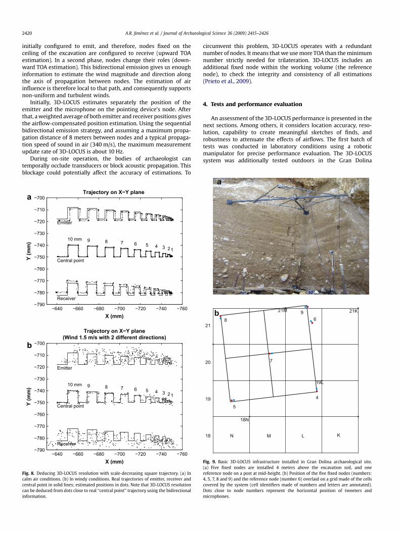
Fig. 8. Deducing 3D-LOCUS resolution with scale-decreasing square trajectory. (a) Incalm air conditions. (b) In windy conditions. Real trajectories of emitter, receiver andcentral point in solid lines; estimated positions in dots. Note that 3D-LOCUS resolutioncan be deduced from dots close to real ‘‘central point’’ trajectory using the bidirectionalinformation.
circumvent this problem, 3D-LOCUS operates with a redundantnumber of nodes. It means that we use more TOA than the minimumnumber strictly needed for trilateration. 3D-LOCUS includes anadditional fixed node within the working volume (the referencenode), to check the integrity and consistency of all estimations(Prieto et al., 2009).
4. Tests and performance evaluation
An assessment of the 3D-LOCUS performance is presented in thenext sections. Among others, it considers location accuracy, reso-lution, capability to create meaningful sketches of finds, androbustness to attenuate the effects of airflows. The first batch oftests was conducted in laboratory conditions using a roboticmanipulator for precise performance evaluation. The 3D-LOCUSsystem was additionally tested outdoors in the Gran Dolina
18N
19L
21K21M
N M L K18
19
20
21
4
5
6
7
89
a
b
Fig. 9. Basic 3D-LOCUS infrastructure installed in Gran Dolina archaeological site.(a) Five fixed nodes are installed 4 meters above the excavation soil, and onereference node on a post at mid-height. (b) Position of the five fixed nodes (numbers:4, 5, 7, 8 and 9) and the reference node (number 6) overlaid on a grid made of the cellscovered by the system (cell identifiers made of numbers and letters are annotated).Dots close to node numbers represent the horizontal position of tweeters andmicrophones.

A.R. Jimenez et al. / Journal of Archaeological Science 36 (2009) 2415–2426 2421
archaeological site, giving the excavators the opportunity to use thetwo types of tools (Section 3.3) for provenance registration.
4.1. Location accuracy and wind influence
Before the installation of the system in Gran Dolina, we evalu-ated the 3D-LOCUS positioning accuracy in laboratory conditions.This tests were performed using a network of seven fixed nodesplaced on a frame at a height of 3 m above the floor. In order toevaluate the system accuracy with enough exactitude, weemployed a Staubli RX90 robotic manipulator as a ground truth.The mobile node was affixed to the wrist of the manipulator andthen moved at 22 different positions within the available workingvolume of the robot. At each position we captured sequences ofmore than 200 measurements in windy and calm air conditions.
The wind was created using an industrial fan able to generateairflows up to 5 m per second. The cumulative errors in localizationusing the bidirectional compensation method are presented inFig. 7. In ideal conditions the positioning error is below 5 mm in 98%of the occurrences; a slight deterioration is perceived in windyconditions but is below 7 mm at the same confidence level. Errorsare no larger than 8 mm, which is an important fact demonstratingthe robustness of the estimation process.
4.2. Trace resolution
In order to evaluate the real capability of the system to sketch anobject, we firstly studied its resolution, i.e. the minimum tooldisplacement that causes a significative change in the positionestimation. For resolution estimation we moved the Staubli robotalong a trajectory that reproduces a sequence of decreasing-sizesquares (10 consecutive steps, with a 1 mm decrease per step,starting at 10 mm). Fig. 8 shows with solid lines the real trajectoriesdescribed by the tweeter, the microphone and the mid-pointbetween both transducers that form part of the mobile node.
The estimated tweeter’s positions, using only upward emissionsin calm air conditions, are represented with a trail of dots close tothe real emitter trajectory in Fig. 8a. Under the same conditions, theestimated microphone’s position is shown with dots in this figure.Some bias is detected on microphone and tweeter trajectories withrespect to the actual path, probably due to errors while positioningthe mobile node on manipulator’s wrist or other calibration errors.The average of both independent position estimations, representedby the intermediate trail of dots in Fig. 8a, is found to perfectly fitthe mid-point real trajectory. From these results it can be deduceda discernible resolution of about 2 mm.
Fig. 10. Using the 3D-LOCUS system in Gran Dolina dig. (a) The short self-levelled rod. (bDisplay of position estimation relative, in this case, to cell 19L.
The resolution was also evaluated in variant windy conditions.The individual estimations of tweeter and microphone are signifi-cantly affected in accuracy and resolution, as can be seen in Fig. 8b(upper and lower cloud of dots). However using the bidirectionalcompensation method proposed in 3D-LOCUS, not only accuracy isimproved (as shown in last section) but the resolution is keptwithout too much degradation. The discernible resolution isapproximately 5 mm.
4.3. Deployment in Gran Dolina
The purpose of the 3D-LOCUS tests in Gran Dolina was to validateits functionality and to get feedback from excavators for furtherrefinements. Since the goal was not yet to substitute the currentmethod of registration, we only covered a fraction of the wholeexcavation site using a minimal sensor network infrastructure.
The 3D-LOCUS installation in Gran Dolina, apart from a PC anda central node, comprised a network of five fixed nodes, a referencenode and two pointing devices (the long and short rods). A squarestructure of 2.4 m side was installed 4 m above the site’s terrain(Fig. 9a). Affixed to this structure, five nodes (numbered 4, 5, 7, 8and 9) are attached in locations shown in Fig. 9b. This 3D-LOCUSdeployment covers an area of 16 m2. The wired reference node, forintegrity monitoring (numbered 6), is placed at a fixed positionover the excavation soil.
The exact 3D position of sensing nodes (microphone and tweeter)was calibrated using a Trimble 3605 total station. Since the totalstation was referenced to the excavation coordinate frame, the 3D-LOCUS nodes are also referred to the same frame as well as allposition estimations.
The excavators used the pointing devices, as shown in Fig. 10.The estimated 3D location of the lower tip of the rod was displayedon the PC’s screen for immediate feedback (Fig. 10c). This infor-mation can include the absolute coordinates, or alternatively themore usual representation relative to a unit cell (cell identity plusrelative coordinates).
4.4. Robustness to turbulent airflows
The bidirectional compensation method to robustly estimatelocation has been experimentally tested in Gran Dolina. Some of thetests in Gran Dolina under windy conditions are shown in Fig. 11a.The measured upward and downward TOA are shown in dashedand dotted lines, respectively. In this case the propagation isbetween reference node 6 and some fixed nodes above the
) The long dual-sensor rod that does not require prior levelling before measuring. (c)
a
1
1.02
1.04x 10⁴
TOF (us) bidirectional between
Node 6 and fixed nodes
TO
F6
,5
6400
6600
6800
TO
F6,7
8800
8900
9000
TO
F6
,8
5450
5500
5550
TO
F6
,9
TimeStamp
b
2.055
2.06
2.065x 10⁴
XYZ vs time (Node 6)
X (m
m)
1.128
1.13
1.132
1.134x 10⁴
Y (m
m)
0 20 40 60 80 100 120 140
0 20 40 60 80 100 120 140
0 20 40 60 80 100 120 140
0 20 40 60 80 100 120 140
0 20 40 60 80 100 120 140
0 20 40 60 80 100 120 140
0 20 40 60 80 100 120 140
−1990
−1980
−1970
Z (m
m)
TimeStamp
c
2.058 2.06 2.062x 10⁴
1.129
1.13
1.131
1.132
1.133x 10⁴ X−Y view (Node 6)
Y (m
m)
X (mm)
2.058 2.06 2.062x 10⁴
−1985−1980−1975
X−Z view (Node 6)
X (mm)
Z (m
m)
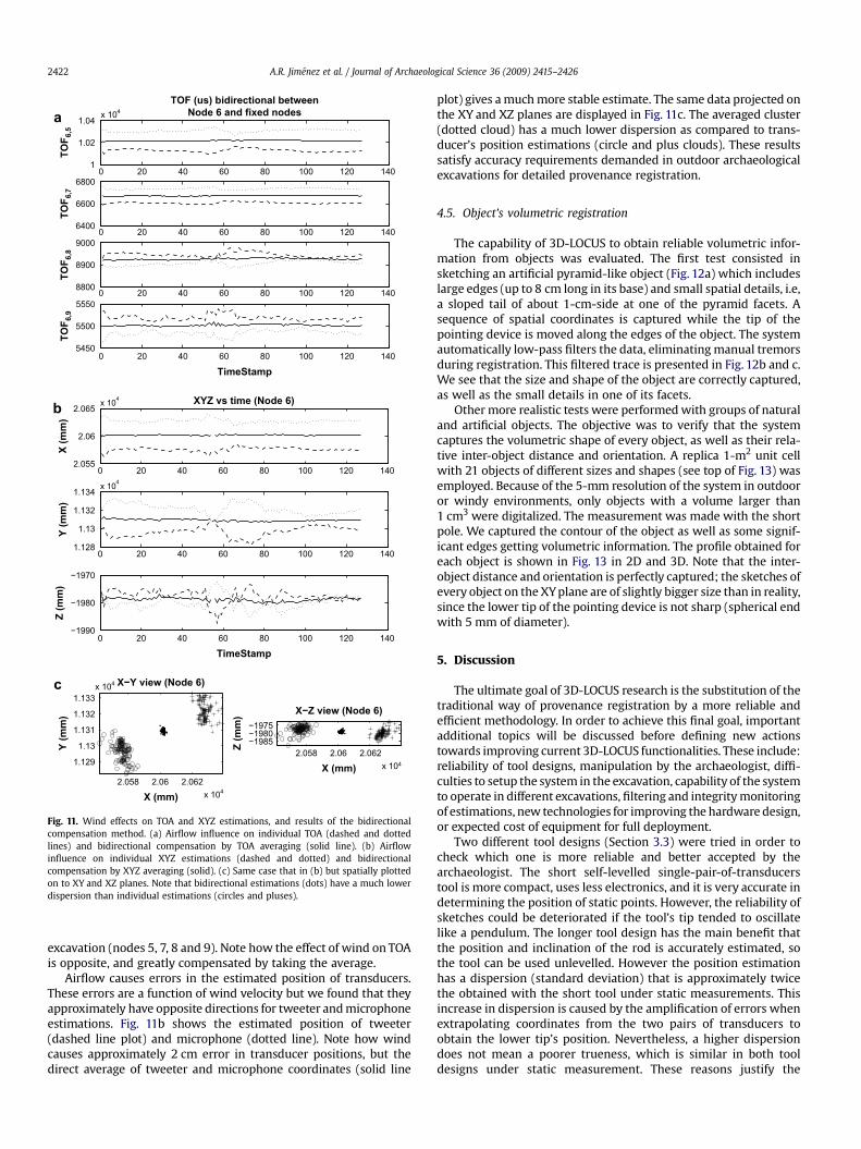
Fig. 11. Wind effects on TOA and XYZ estimations, and results of the bidirectionalcompensation method. (a) Airflow influence on individual TOA (dashed and dottedlines) and bidirectional compensation by TOA averaging (solid line). (b) Airflowinfluence on individual XYZ estimations (dashed and dotted) and bidirectionalcompensation by XYZ averaging (solid). (c) Same case that in (b) but spatially plottedon to XY and XZ planes. Note that bidirectional estimations (dots) have a much lowerdispersion than individual estimations (circles and pluses).
A.R. Jimenez et al. / Journal of Archaeological Science 36 (2009) 2415–24262422
excavation (nodes 5, 7, 8 and 9). Note how the effect of wind on TOAis opposite, and greatly compensated by taking the average.
Airflow causes errors in the estimated position of transducers.These errors are a function of wind velocity but we found that theyapproximately have opposite directions for tweeter and microphoneestimations. Fig. 11b shows the estimated position of tweeter(dashed line plot) and microphone (dotted line). Note how windcauses approximately 2 cm error in transducer positions, but thedirect average of tweeter and microphone coordinates (solid line
plot) gives a much more stable estimate. The same data projected onthe XY and XZ planes are displayed in Fig. 11c. The averaged cluster(dotted cloud) has a much lower dispersion as compared to trans-ducer’s position estimations (circle and plus clouds). These resultssatisfy accuracy requirements demanded in outdoor archaeologicalexcavations for detailed provenance registration.
4.5. Object’s volumetric registration
The capability of 3D-LOCUS to obtain reliable volumetric infor-mation from objects was evaluated. The first test consisted insketching an artificial pyramid-like object (Fig. 12a) which includeslarge edges (up to 8 cm long in its base) and small spatial details, i.e,a sloped tail of about 1-cm-side at one of the pyramid facets. Asequence of spatial coordinates is captured while the tip of thepointing device is moved along the edges of the object. The systemautomatically low-pass filters the data, eliminating manual tremorsduring registration. This filtered trace is presented in Fig. 12b and c.We see that the size and shape of the object are correctly captured,as well as the small details in one of its facets.
Other more realistic tests were performed with groups of naturaland artificial objects. The objective was to verify that the systemcaptures the volumetric shape of every object, as well as their rela-tive inter-object distance and orientation. A replica 1-m2 unit cellwith 21 objects of different sizes and shapes (see top of Fig. 13) wasemployed. Because of the 5-mm resolution of the system in outdooror windy environments, only objects with a volume larger than1 cm3 were digitalized. The measurement was made with the shortpole. We captured the contour of the object as well as some signif-icant edges getting volumetric information. The profile obtained foreach object is shown in Fig. 13 in 2D and 3D. Note that the inter-object distance and orientation is perfectly captured; the sketches ofevery object on the XY plane are of slightly bigger size than in reality,since the lower tip of the pointing device is not sharp (spherical endwith 5 mm of diameter).
5. Discussion
The ultimate goal of 3D-LOCUS research is the substitution of thetraditional way of provenance registration by a more reliable andefficient methodology. In order to achieve this final goal, importantadditional topics will be discussed before defining new actionstowards improving current 3D-LOCUS functionalities. These include:reliability of tool designs, manipulation by the archaeologist, diffi-culties to setup the system in the excavation, capability of the systemto operate in different excavations, filtering and integrity monitoringof estimations, new technologies for improving the hardware design,or expected cost of equipment for full deployment.
Two different tool designs (Section 3.3) were tried in order tocheck which one is more reliable and better accepted by thearchaeologist. The short self-levelled single-pair-of-transducerstool is more compact, uses less electronics, and it is very accurate indetermining the position of static points. However, the reliability ofsketches could be deteriorated if the tool’s tip tended to oscillatelike a pendulum. The longer tool design has the main benefit thatthe position and inclination of the rod is accurately estimated, sothe tool can be used unlevelled. However the position estimationhas a dispersion (standard deviation) that is approximately twicethe obtained with the short tool under static measurements. Thisincrease in dispersion is caused by the amplification of errors whenextrapolating coordinates from the two pairs of transducers toobtain the lower tip’s position. Nevertheless, a higher dispersiondoes not mean a poorer trueness, which is similar in both tooldesigns under static measurement. These reasons justify the

460480
500520
540
550
600
650
700−300
−290
−280
−270
−260
−250
X (mm)
Tridimensional trace of piramid−like object
Y (mm)
Z (m
m)
480 500 520580
590
600
610
620
630
640
650
660
670
680
XY projection of piramid−like object’s trace
X (mm)
Y (m
m)
a
b
c
Fig. 12. Sketching a regular object using 3D-LOCUS. (a) A pyramid-like object with some low profile details and straight and curved edges (size: L 80 mm�W 60 mm�H 45 mm).(b) Resulting estimated 3D trace of this object. (c) Projection of 3D trace on XY plane (traditional representation of find’s shape).
A.R. Jimenez et al. / Journal of Archaeological Science 36 (2009) 2415–2426 2423

0 200 400 600 800 1000
0
100
200
300
400
500
600
700
800
900
1000
1 2
3
4
5 67
8
9 10 11
1213 1415
16 17 1819
20
21
X (mm)
Y (m
m)
300400
500600
700800
9001000
4500
600700
800900
1000Y (mm)
X (mm)
a
b
c
Fig. 13. Sketching, with 3D-LOCUS, several objects within a square cell of 1 m side. At the top, a photograph of the cell containing 21 objects. In the middle, an XY projection of thetraces captured with 3D-LOCUS. At the bottom, a 3D representation of captured traces.
A.R. Jimenez et al. / Journal of Archaeological Science 36 (2009) 2415–24262424

A.R. Jimenez et al. / Journal of Archaeological Science 36 (2009) 2415–2426 2425
filtering of position estimations from both tool designs to alleviatethe oscillation impact and the extrapolation effects.
From the archaeologists’ point of view, the short self-levelledtool it is not ideal for tracing object’s contours, since the pointingdevice has to be moved with one hand very slowly to avoidpendular oscillations. If they occur, the other hand has to be used toattenuate them (see Fig. 10a). Since the short tool is prepared to bevertically aligned, it is not valid for registering objects in placeswhere the tool cannot be kept upright (e.g. object close to a wallthat is inclined over the excavation area). On the other hand, thelong tool design, is heavier and bulkier. It has to be manipulatedwith both hands, one positioned at the tool’s center of mass to holdits weight, and the other one close to the lower tip, pointing to thelocation of interest. The main advantage is that the long tool can bemanipulated in a more agile and quick manner. Besides, the tool canbe inclined to locate objects in areas of difficult access. For thesereasons, most of the archaeologists believe that the long rod designis more versatile and easy to use.
During measurement it is recommended not to contact the lowertip of the pointing device with the object to avoid any damage ordisplacement of the find. For that reason, when the user presses thebutton to start a measurement, the tool tip should be a few milli-meters away from the object’s surface, until the measurement ends.The archaeologist knows when measurements are being taken placebecause he/she receives an acoustic feedback. This sound beep iscreated by the acoustic emissions for inter-node ranging, whichhave part of their transmitted energy band (5–25 kHz) in theaudible region. This way of operation has resulted positive from thepoint of view of archaeologists to let them know when measure-ments actually take place.
The current 3D-LOCUS prototype has been tested with twopointing devices operating in parallel. These tests were restrictedby the number of tools available, but the design is prepared toadmit more tools in parallel. The requests prompted by each tool tostart a measurement are attended by time-multiplexing by thecentral node. Since the update rate for a single tool is about 10 Hz,the response time after a button is pressed in a tool depends on thenumber of simultaneous requests. It is expected a maximum delayof 1 s, between the action of pressing a button and the actualbeginning of the measurement, if 10 tools are requesting a singlepoint measurement at the same time. For continuous measure-ments (sketching objects) the number of parallel sketches is morelimited. A maximum of two sketches at a time is recommended inorder to avoid the acquisition of too few points per trace.
Each tool has its own identification code, so parallel measure-ments are not confused, and the central node knows which positionestimation corresponds to what tool. Additionally, although notimplemented yet in the current prototype, 3D-LOCUS tools coulduse their Bluetooth channels to receive a unique identification labelfor the particular find under provenance. This is possible sincearchaeologists in Gran Dolina already obtain a unique identificationlabel per find while they use a PDA (Personal Digital Assistant) forannotating other descriptive features such as the find’s taxonomy. Aserver computer is in charge of generating new identification labelswhenever a PDA requests the storage of data in the server database.This is a very interesting feature that could guarantee the integrityof data (object ID, position, taxonomy, etc.) in a unique record in theexcavation database.
The 3D-LOCUS system can be adapted to the shape and size ofa particular dig, by adequately distributing the necessary number ofnodes over the excavation. For this purpose, the authors havedeveloped a software tool (Laguna et al., 2009) that, given a desiredarea for localization and the type of transducers used, generates anoptimal layout of nodes that minimizes cost (number of nodes)while giving maximum accuracy and coverage.
In order to install the network of sensor nodes over the exca-vation, a specially designed frame or ceiling is needed to secure thenodes at fixed positions. To avoid the re-calibration of all nodesfrequently, which could take a couple of hours, it is recommendedto do the installation once at the beginning of the excavationcampaign, and keep it until the end of the season. This proceduremeans to leave the sensors overnight, which is problematic if thesite is not watched out because vandals could damage the equip-ment. Nevertheless, as sensors are placed at a significant heightabove the terrain (4 m), damage is not too likely. The maintenanceof the equipment during the excavation campaign only consists incharging the batteries of each tool during the night.
3D-LOCUS was tested in open-spaces and in trenches, howeverthe installation of 3D-LOCUS in caves could also be possible.Reverberation in a cave could affect 3D-LOCUS performance due tomultipath propagation. A further study should be done to check itsoperation in caves and to determine if it is necessary to includeadvanced multipath-cancellation techniques.
Noise reduction techniques such as Kalman filters are a commonpractice to reduce the variance of noise-corrupted estimations. Thepositioning results presented along this paper for accuracy andresolution determination are obtained without the help of anyKalman-like filter. The only results that are automatically smoothed(for tremor suppression) are those presented in Figs. 12 and 13corresponding to the profiling of objects. The implementation ofKalman filters, robust estimators and auto-calibration methods willfurther improve the results already presented, making possiblevery repetitive estimations and probably errors below 5 mm inalmost all conditions.
Some new technologies could be used to improve the hardwaredesign of 3D-LOCUS. One possibility could be to convert all sensingnodes to wireless using mesh-like or ad-hoc communicationsprotocols (e.g. Zigbee). If so, cabling among nodes would be elimi-nated and a more flexible non-centralized inter-node communica-tion could be implemented. The energy for powering nodes could beobtained from batteries connected to local solar panels. Additionally,other types of omnidirectional broadband transducers could be usedin order to increase the number of simultaneous pointing devices ina dig, and to minimize the number of nodes for a complete instal-lation (Gran Dolina could need about 20 nodes). Some new trans-ducer designs based on ferroelectrectric films are being studied byour group to achieve this goal (Ealo et al., 2006, 2008).
The cost of the equipment required to achieve a full 3D-LOCUSdeployment on a excavation is very important. The most expensivecomponents within a node are the Texas Instruments 2812 DSP chip(25 $), the Visaton CP13 tweeter (40 $) and the Bluetooth commu-nication module (50 $). At this stage we cannot assume wholesaleprices, therefore retail costs imply a minimum of 250 $ per node. Thismeans that a 100 m2 excavation needing a total of 20 fixed nodes,a pair of reference nodes, two rod tools, a central node and a laptopcomputer, can cost about 8000 $ (no engineering and fabricationcosts included). Consequently, the price for a 3D-LOCUS-like prove-nance registration equipment is expected to be similar to a commonmid-performance total station (about 15,000 $). After a hypotheticalcommercial exploitation of 3D-LOCUS prototype, a decrease inequipment costs is expected, but this effect would be dictated by thevolume market of archaeological sites around the world.
6. Conclusions
This paper has presented a new sensor equipment (3D-LOCUS)based on the bidirectional acoustic propagation of signals in air tomeasure the three-dimensional position of finds in archaeologicalexcavations. This system can also be used to trace the outline ofnatural objects and artifacts, and therefore to accurately register
A.R. Jimenez et al. / Journal of Archaeological Science 36 (2009) 2415–24262426
their size, shape and orientation. In the paper, we described the 3D-LOCUS architecture, which consists of a network of distributedintelligent nodes installed above the excavation site, a central nodefor centralized synchronization and communication, a personalcomputer, and some portable wireless tools. Advanced processingDSP-based platforms and broadband transducers in each nodeallow the use of spread spectrum signal coding in order to achievemultiple access and good ranging accuracy. A bidirectional trilat-eration scheme is used to minimize errors provoked by turbulentairflows. Tests in laboratory conditions and in a real excavation sitewere performed.
The typical location accuracies obtained without filtering arebelow 10 mm in natural conditions, and the achieved resolution isabout 5 mm. Results are good at obtaining the find’s profile on thehorizontal plane, and also capturing significative edges on itssurface. The long rod resulted easier to manipulate and moreversatile. The time required to capture objects, after some initialtraining, is faster than manual drawing, and is more accurate, sinceit places objects correctly in space capturing simultaneously loca-tion, shape and orientation.
The next actions to improve 3D-LOCUS prototype, probably willbe focused towards improving the ergonomy and ease of use oftools; applying robust techniques to filter out Gaussian and non-Gaussian noise; employing communication protocols like Zigbee tocreate a total mesh-like wireless node network; and studying newtransducing methods to further reduce the node density to cover anexcavation area. The study of the applicability of the system in cavescan also be investigated by implementing multipath cancellationtechniques. It also would be desirable to have a faster installationand calibration of the system.
We believe that the 3D-LOCUS concept and realization repre-sents a significant contribution in the computerization of archae-ological sites. It has the ultimate goal of replacing the traditionalway of provenance registration by a more reliable and efficientmethodology. A practical consequence of this new methodology isa significant reduction of the time needed by an archeologist tocapture and verify that their spatial annotations and drawings arecorrect. This data could be automatically transferred to a databasein conjunction with other find’s features. These facts finally implya more productive and efficient excavation. Consequently moretime will be available for the analysis and interpretation of results,and less for non-scientific systematic tasks.
Acknowledgements
This work has been supported by the Spanish Atapuerca Foun-dation who also helped in the evaluation of the system in the GranDolina archaeological site. The fundamental acoustic positioningresearch was funded by the Spanish Ministry of Science andTechnology under PARMEI research (Ref. DIP2003-08715-C02-02)and some other previous projects.
References
Alvarez, F.J., Urena, J., Mazo, M., Hernandez, A., Garcıa, J.J., Marziani, C., 2006. Highreliability outdoor sonar prototype based on efficient signal coding. IEEE Trans-actions on Ultrasonics, Ferroelectrics and Frequency Control 53 (10), 1862–1871.
Bahl, P., Padmanabhan, V.N., 2000. Radar: an in-building user location and trackingsystem. In: Proceedings of the IEEE Infocom, Tel Aviv. pp. 775–784.
Balakrishnan, H., Priyantha, N., 2003. The cricket indoor location system: experi-ence and status. WorkShop on location-aware computing, Ubicomp, p. 7–9.
Colosi, F., Gabrielli, R., Rose, D., 2001. Integrated use of DGPS and the total station forthe survey of archaeological sites: the case of Colle Breccioso. ComputingArchaeology for Understanding the Past. Computer Applications and Quanti-tative Methods in Archaeology. Archaeopress, Oxford, pp. 9–12.
Dibble, H.L., 1987. Measurement of artifact provenience with an electronic theod-olite. Journal of Field Archaeology 14, 249–254.
Dibble, H.L., McPherron, S.P., 1988. On the computarization of archaeologicalprojects. Journal of Field Archaeology 15 (4), 431–440.
Doran, J.E., Hodson, F.R., 1975. Mathematics and Computers in Archaeology. Edin-burgh University Press.
Ealo, J.L., Jimenez, A.R., Seco, F., Prieto, C., Roa, J., Ramos, F., Guevara, J., 3–6 October2006. Broadband omnidirectional ultrasonic transducer for airborne ultrasoundbased on EMFi. IEEE International Ultrasonics Symposium, Vancouver-CA, pp.544–545.
Ealo, J.L., Seco, F., Jimenez, A.R., 2008. Broadband EMFi-based airbone ultrasonictransducers for robotic applications. IEEE Transactions on Ultrasonics, Ferro-electrics and Frequency Control 55 (4), 919–928.
Fernandez-Jalvo, Y., Andrews, P., 1992. Small mammal taphonomy of Gran Dolina,Atapuerca (Burgos), Spain. Journal of Archaeological Science 19, 407–428.
Fontana, R.J., Gunderson, S.J., 2002. Ultra-wideband precision asset location system.In: Proceedings of IEEE Conference on Ultra Wideband Systems and Technol-ogies, Baltimore, pp. 147–150.
Hazas, M., Hopper, A., 2006. Broadband ultrasonic location systems for improvedindoor positioning. IEEE Transactions on Mobile Computing 5 (5), 536–547.
Hightower, J., Borriello, G., 2001. Location systems for ubiquitous computing. IEEEComputer 34 (8), 57–66.
Jimenez, A.R., Seco, F., 2005. Precise localisation of archaeological findings witha new ultrasonic 3D positioning sensor. Sensors and Actuators A 123–124,224–233.
Koutsou, A.D., Seco, F., Jimenez, A.R., Roa, J., Ealo, J., Prieto, C., Guevara, J., 3–5October 2007. Preliminary localization results with an RFID based indoorguiding system. IEEE International Symposium on Intelligent Signal Processing,Alcala de Henares, Spain, pp. 1–6.
Krumm, J., Harris, S., Meyers, B., Brumitt, B., Hale, M., Shafer, S., 2000. Multi-cameramultiperson tracking for easyliving. Third IEEE International Workshop onVisual Surveillance (VS2000), pp. 3–10.
Laguna, M., Roa, J.O., Jimenez, A.R., Seco, F., 2009. Diversified local search for optimallayout of beacons in an indoor positioning system. IIE Transactions Desing andManufacturing 41 (3), 247–259.
Martın-Abreu, J.M., Jimenez, A.R., Seco, F., Calderon, L., Pons, J.L., Ceres, R., 2002.Estimating the 3D-position from time delay data of us-waves: experimentalanalysis and new processing algorithm. Sensors and Actuators A 101, 311–321.
McPherron, S.J.P., 2005. Artifact orientations and site formation processes from totalstation proveniences. Journal of Archaeological Science 32, 1003–1014.
Misra, P., Enge, P., 2006. Global Positioning System: Signals, Measurements, andPerformance. Ganga-Jamuna Press, MA, ISBN 0-9709544-1-7.
Ni, L.M., Liu, Y., Lau, Y.C., Patil, A.P., 2004. Landmarc: indoor location sensing usingactive RFID. Wireless networks. Special Issue on Pervasive Computing andCommunications 10 (6), 701–710.
Oppenheim, V., Schafer, R.W., Buck, J.R., 1999. Discrete-Time Signal Processing.Pretince Hall.
Popovic, B.M., 1999. Efficient Golay correlator. Electronics Letters 35, 1427–1428.Prieto, J.C., Jimenez, A.R., Guevara, J., Ealo, J., Seco, F., Roa, J., Ramos, F., 3–5 October
2007. Subcentimeter-accuracy localization through broadband acoustic trans-ducers. IEEE International Symposium on Intelligent Signal Processing, Alcalade Henares, Spain, pp. 1–6.
Prieto, J.C., Jimenez, A.R., Guevara, J., Ealo, J., Seco, F., Roa, J., Koutsou, A., 6–8 May2008. Robust regression applied to ultrasound location systems. In: Proceedingsof IEEE/ION PLANS, Monterey, California, USA, pp. 181–186.
Prieto, J.C., Jimenez, A.R., Guevara, J., Ealo, J., Seco, F., Roa, J., Ramos, F., 2009.Performance evaluation of 3D-LOCUS advanced acoustic LPS. IEEE Transactionson Intrumentation and Measurement 58 (8), 2385–2395.
Schindler, K., Grabner, M., Leberl, F., 2003. Fast on-site reconstruction and visuali-zation of archaeological finds. In: Proceedings of CIPA Symposium, Antalya,Turkey.
Tack, F., Debie, J., Goossens, R., De Meulemeester, J., Devriendt, D., 2005. A feasiblemethodology for the use of close range photogrammetry for the recording ofarchaeological excavations. In: XX CIPA International Symposium, Torino, Italy.
Want, R., Hopper, A., Falcao, V., Gibbons, J., 1992. The active badge location system.ACM Transations Information Systems 10, 91–102.
Wheatley, D., Gillings, M., 2002. Spatial technology and archaeology. The Archae-ological Application of GIS. Taylor & Francis, London.
Werb, J., Lanzl, C., 1998. Designing a positioning system for finding things andpeople indoors. IEEE Spectrum, 71–78.