journal of intelligent material systems and structuresrbatra/pdfpapers/intelligentmaterial...journal...
TRANSCRIPT

http://jim.sagepub.com/Structures
Journal of Intelligent Material Systems and
http://jim.sagepub.com/content/12/3/165The online version of this article can be found at:
DOI: 10.1106/MW7X-YEJK-17XD-GD2N
2001 12: 165Journal of Intelligent Material Systems and StructuresB. Jiang and R. C. Batra
Micromechanical Modeling of a Composite Containing Piezoelectric and Shape Memory Alloy Inclusions
Published by:
http://www.sagepublications.com
can be found at:Journal of Intelligent Material Systems and StructuresAdditional services and information for
http://jim.sagepub.com/cgi/alertsEmail Alerts:
http://jim.sagepub.com/subscriptionsSubscriptions:
http://www.sagepub.com/journalsReprints.navReprints:
http://www.sagepub.com/journalsPermissions.navPermissions:
http://jim.sagepub.com/content/12/3/165.refs.htmlCitations:
What is This?
- Mar 1, 2001Version of Record >>
at Virginia Tech on November 15, 2013jim.sagepub.comDownloaded from at Virginia Tech on November 15, 2013jim.sagepub.comDownloaded from

Micromechanical Modeling of a Composite ContainingPiezoelectric and Shape Memory Alloy Inclusions
B. JIANG AND R. C. BATRA*
Department of Engineering Science and Mechanics, MC 0219, Virginia Polytechnic Institute
and State University, Blacksburg, VA 24061
ABSTRACT: Macroscopic constitutive relations based on the mean-field theory and theMori–Tanaka method are derived for a 3-phase composite consisting of a polymer matrix andshape memory alloy (SMA) and piezoceramic (PZT) inclusions. Effective moduli arecomputed for likewise oriented spherical and cylindrical inclusions. Results are also computedfor cylindrical PZT and ellipsoidal SMA inclusions. Even though the PZT and the matrixmaterials are assumed to be linear, the overall response of the composite is nonlinear becauseof the phase transformations in the SMA inclusions. The 3-phase composite exhibitspyroelectric effects even when none of its constituents is pyroelectric. It is found that thespherical inclusions are more effective than the cylindrical inclusions in the sense that lowervalues of the average axial stress induce phase transformations in the SMA inclusions, and themaximum principal tensile strain induced in the PZT inclusions is only about 7% ofthe average axial strain. However, spherical PZT inclusions require a very high value of theelectric field to induce any noticeable axial strain in the hybrid composite.
INTRODUCTION
A‘‘smart composite’’ should be distinguished from anordinary composite that is primarily used as a
structural material. A smart composite can be tailoredto control its shape when subjected to different loads.One or more constituents of a smart composite andhence the composite itself exhibits coupling between atleast two of the following four effects: mechanical,thermal, electrical and magnetic. Thus, besides thepolymer matrix, other constitutents of a smart compo-site can be a piezoceramic, a shape memory alloy, and/or a magnetostrictive material.A variety of piezoelectric composite materials, usually
called piezocomposites, can be made by combininga piezoelectric ceramic (PZT) with either a non-piezo-electric or a piezoelectric polymer phase; e.g. see the website (http://www.matsysinc.com/piezopg.html) forpiezocomposites made by Materials System Inc. Soonafter the appearance of barium titanate as a usefulpiezoelectric ceramic, researchers at the Naval ResearchLaboratory embedded it in a polymer matrix tomake a flexible hydrophone material (Smith, 1989).Pauer (1973) made flexible piezocomposites bycombining lead zirconate-titanate ceramic powderswith a polymer. Measurements showing the potentialfor improvement in the performance of naval
hydrophones provided a major impetus to research onpiezocomposites (Harrison, 1976).
Piezocomposites have been used as electromechanicaland medical ultrasonic imaging transducers. They aremore suitable for damage monitoring due to the easewith which their mechanical properties can be tailored,and better impedance matching with that of the hoststructure. By altering the shape, the size, the volumefraction of the PZTs, and the material of the two phases,a cost-effective piezo-composite with the desired elec-tromechanical coupling constants and impedance can bemanufactured.
Newnham et al.’s (1978, 1980) connectivity theorycharacterized piezocomposites according as the phasesare connected in series or in parallel. They alsodetermined the effective properties of these composites.Banno (1983) extended their analyses to discontinuousPZT fibers, and Smith and Auld (1991) to continuousPZT fibers. Smith and Auld (1991) studied the thick-ness-mode oscillations in thin plates of 1–3 piezo-composites. Such piezocomposites can be treated as ahomogeneous medium with new effective materialproperties so long as the size of the PZT rods andtheir spacings are sufficiently fine compared with allrelevant acoustic wavelengths. Badcock and Birt (2000)have described a technique used to prepare and pole 0–3piezocomposites, and have also computed their electro-mechanical properties.
One way to compute effective properties of a piezo-composite is to use the Eshelby tensor for a PZT
JOURNAL OF INTELLIGENT MATERIAL SYSTEMS AND STRUCTURES, Vol. 12—March 2001 165
1045-389X/01/03 0165-18 $10.00/0 DOI: 10.1106/MW7X-YEJK-17XD-GD2N� 2001 Sage Publications
*Author to whom correspondence should be addressed.E-mail: [email protected]
at Virginia Tech on November 15, 2013jim.sagepub.comDownloaded from

inclusion in an infinite matrix. Several researchers (e.g.see Deeg (1980), Wang (1992), Dunn and Taya (1993),Chen (1994), Hwang and Yu (1994), Jiang et al. (1997))have derived Eshelby tensors for piezocomposites. Ifboth the matrix and the inclusions exhibit coupledelectromechanical properties, then the Eshelby tensor isexpressed in terms of four Green’s functions which aredifficult to obtain in closed form. However, for apiezocomposite made of piezoelectric inclusionsembedded in a non-piezoelectric matrix, only twoGreen’s functions suffice to describe the electroelasticEshelby tensors (e.g. see Jiang et al. (1997)) and theirclosed form expressions can be obtained. Benveniste andDvorak (1990), and Schulgasser (1992) have providedinternal consistency relations between the effectivemoduli of a piezocomposite with continuous PZTfibers. Benveniste (1993a,b) and Benveniste andDvorak (1990) have generalized the fields concept ofDvorak (1990) to the coupled electroelastic behavior ofa piezocomposite. Dunn and Taya (1993) consideredellipsoidal PZT inclusions in a non-piezoelectric elasticmatrix and used various micromechanics models tostudy their electromechanical properties. Dunn (1994)has proved that a piezocomposite can exhibit pyro-electric effects even though neither of its constituents ispyroelectric. He has also estimated the effective thermalexpansion and pyroelectric coefficients of a two-phasepyroelectric composite (Dunn, 1993b). The interactionsamong densely distributed inclusions or inhomogeneitiesare usually approximated by the Mori–Tanaka (1973)mean field approach. For small concentrations ofinclusions, one can use the rule of mixtures to computethe effective properties of a piezocomposite. An alter-native to these analytical techniques is to numericallyanalyze deformations of a representative volume ele-ment of a piezocomposite, and determine materialproperties of an equivalent homogenized system; e.g.see Gabbert et al. (1999).It is rather well known that PZT actuators supply a
small actuation strain but respond quickly to the appliedelectric field. However, shape memory alloy (SMA)actuators exert significant actuation strains but respondslowly. We take advantage of the beneficial properties ofthese two materials and study composites made of SMAand PZT inclusions embedded in an elastic matrix.Bidaux et al. (1995), Hamada et al. (1997) and Lee et al.(1997) have developed manufacturing and processingtechniques for embedding SMA particles into either anelastic or a ductile matrix. The strengthening effect ofSMA wires in an elastic matrix has been studied byArmstrong and Kino (1995), Furuya et al. (1993) andYamada et al. (1993). The constitutive properties of anSMA composite with an elastic matrix have beenstudied, amongst others, by Boyd and Lagoudas(1994), Jonnalagadda and Sottos (1995), Sottos et al.(1996), Stalmans et al. (1997), and Sun and Sun (1995).
A micromechanical model of an SMA composite withan elastoplastic matrix has been proposed and analyzedby Cherkaoui et al. (1998) and Song et al. (1999). Theyhave also used a self-consistent scheme to determine theeffective properties of an SMA composite in whichidentical ellipsoidal SMA inclusions are unidirectionallyaligned. Taya et al. (1995), Song et al. (1999) andFuruya et al. (1997) used the Eshelby tensor to predictthe compressive stress in the matrix material of aSMA composite that was prestrained at the room tem-perature and then subjected to a temperature increasebeyond the austenitic finish temperature. This com-pressive stress significantly enhanced the tensile pro-perties of a NiTi (Nickel Titanium) SMA fiber/Aluminum matrix composite and of a NiTi SMA fiber/epoxy matrix composite. Other phenomenologicalmacroscopic constitutive models (e.g., Tanaka et al.1986; Liang and Rogers, 1990; Raniecki et al., 1992;Bekker and Brinson, 1997), and micromechanicalmodels based on the mean field theory (e.g. Patooret al., 1988; Sun and Hwang, 1993; Boyd and Lagoudas,1996; Song et al., 1997; Lu and Weng, 1997) have alsobeen proposed. Fischer et al. (1996) and Birman (1997)have reviewed the research on the SMAs.
Because the behavior of a SMA fiber can be modeledas either pseudoelastic (Muller, 1998) or thermo-elasto-plastic (Cherkaoui et al., 2000) and it undergoes a phasetransformation with a change in temperature, and thePZT fiber’s response is electro-elastic, the macroscopicresponse of a hybrid composite consisting of PZT andSMA fibers in an elastic matrix will be thermo-electro-elasto-plastic. In order to keep the analysis tractable,only infinitesimal deformations are considered. This isreasonable because the PZT is a brittle material with anultimate tensile strain of about 2%.
Here we use the mean field theory and the Mori–Tanaka method to derive macroscopic constitutiverelations of a composite consisting of a polymermatrix and PZT and SMA inclusions. As shown byDunn (1993b) for a piezocomposite, the three-phasecomposite studied herein exhibits pyroelectric propertieseven when none of its constituents is pyroelectric. Forcylindrical PZT and SMA inclusions, the axial straininduced by an applied axial electric field decreases as thevolume fraction of the PZT inclusions is increased.Results are also computed when PZT and SMAinclusions are spherical.
CONSTITUTIVE RELATIONS FOR THE MATRIX
AND THE INCLUSIONS
A schematic sketch of the problem studied is shown inFigure 1. Figures 2a and 2b respectively depict acomposite with all cylindrical and all spherical PZTand SMA inclusions. We presume that the matrix and
166 B. JIANG AND R. C. BATRA
at Virginia Tech on November 15, 2013jim.sagepub.comDownloaded from

the SMA are nonpiezoelectric, the response of PZTinclusions and the matrix material can be modeled aslinear, the deformations are infinitesimal, the values ofthe material parameters of the matrix, the PZT and theSMA are independent of the time and the temperature,the inclusions are perfectly bonded to the matrix, andthe temperature of the composite is always uniform. Inrectangular Cartesian coordinates, the constitutiverelations for the matrix, the PZT inclusions and theSMA are
�ij ¼ CMijkl�kl � �Mij �, Di ¼ kMij Ej þ pMi �,
for the matrix, ð1Þ
�ij ¼ CPijkl�kl � ePkijEk � �Pij �, Di ¼ ePijk�jk þ kPijEj
þ pPi �, for the PZT, ð2Þ
�ij ¼ CSijklð�kl � �trklÞ � �Sij�, Di ¼ kSijEj þ pSi �,
for the SMA: ð3Þ
Here �ij is the stress tensor, �ij the strain tensorappropriate for infinitesimal deformations, �trij thetransformation strain in the SMA, Ei the electric field,� the change in the temperature from that in the ref-erence configuration, Cijkl ¼ Cklij ¼ Cijlk are the elasti-cities, �ij the stress-temperature moduli, kij the dielectricconstants, pi the pyroelectric coefficients, and eijk the
Figure 2a. The hybrid composite with cylindrical PZT and SMAinclusions.
Figure 2b. The hybrid composite with spherical PZT and SMAinclusions.
Figure 1. A schematic sketch of the problem studied.
Micromechanical Modeling of a Composite Containing Piezoelectric and Shape Memory Alloy Inclusions 167
at Virginia Tech on November 15, 2013jim.sagepub.comDownloaded from

piezoelectric constants. Superscripts M and P signify,respectively, quantities for the matrix and the PZT.We note that two phases, namely austenite and
martensite, can coexist in the SMA. The materialproperties of an SMA can be determined from thoseof the austenite and the martensite phases by usingeither the mean field theory or the energy equivalencemethod or the rule of mixtures. Following Boyd andLagoudas (1994) we assume that the rule of mixturesapproximates well the overall properties of an SMA.Thus
CSijkl ¼ ð1� �ÞCa
ijkl þ �Cmijkl ð4Þ
and similar relations hold for kSij , �Sij and pSi , where �S
ij
are the coefficients of thermal expansion of the SMA. InEquation (4), superscripts S, a and m signify quantitiesfor an SMA, austenite and martensite respectively. Thevolume fraction � of the martensite phase is given by
� ¼�tre�trmax
, �tre ¼2
3�trij �
trij
� �1=2
, ð5Þ
where �trij is the transformation induced strain in theSMA, and �trmax is the maximum value of the equivalenttransformation strain, �tre , which is regarded as amaterial property (Song et al., 1999). We note that�Sij ¼ CS
ijkl�Skl .
EFFECTIVE MODULI OF THE HYBRID
COMPOSITE
Let �M , �P and �S denote respectively the regionsoccupied by the matrix, the PZT inclusions and theSMA inclusions. Constitutive relations (1), (2) and (3)can be written as
�ijðxÞ ¼ CijklðxÞ�klðxÞ � ekijðxÞEkðxÞ � �ijðxÞ�ðxÞ þ ��ijðxÞ,
DiðxÞ ¼ eijkðxÞ�jkðxÞ þ kijðxÞEjðxÞ þ piðxÞ�ðxÞ: ð6Þ
If x 2 �M , �P or �S, the material parameters in (6)are, respectively, those for the matrix, the PZT and theSMA. When x 2 �P or �M , ��
ijðxÞ ¼ 0. However, forx 2 �S, ��
ijðxÞ ¼ �CSijkl�
trkl . This essentially smears the
austenite/martensite together into a homogeneousmedium. A more sophisticated treatment would havebeen to consider the martensite moduli and thetransformation strain to compute the transformationinduced stress.We assume that the hybrid composite can be regarded
as statistically homogeneous, and the transformationstrains in the SMA can also be assumed to be statisticallyhomogeneous. The effective thermo-electro-elastic
constants of the hybrid composite are defined by therelations
���ij ¼ �CCijkl ���kl � �eekij �EEk � ���ij ��� þ ����ij,
�DDi ¼ �eeijk ���jk þ �kkij �EEj þ �ppi ��� þ �DD��i , ð7Þ
where ����ij and
�DD�"i are, respectively, the residual stress
and the residual electric displacement caused by thetransformation strain, and an overbar on a quantitydenotes its volume average over the entire domain � ofthe hybrid composite, or over the rth phase �r ðr ¼ P,S or MÞ as is appropriate. For example
��� ¼ �h i ¼1
�
Z�
� d�: ð8Þ
Let displacements corresponding to the uniformstrain �0ij, the electric potential corresponding to theuniform electric field E0
i and the uniform temperature �0
be applied on the boundary @� of �. Then underequilibrium conditions, the fields within � are given by
���ijðxÞ ¼ �0ij ,�EEiðxÞ ¼ E0
i ,���ðxÞ ¼ �0: ð9Þ
However, in general
�ijðxÞ ¼ LijklðxÞ�0kl þNijkðxÞE
0k þ RijðxÞ�
0 þ ���ij ðxÞ,
EiðxÞ ¼ PijkðxÞ�0jk þQijðxÞE
0j þ JiðxÞ�
0 þ E��i ðxÞ, ð10Þ
where the influence functions L,N,R,P,Q and J, andthe concentration tensors ���ij and E��
i obtained by theMori–Tanaka method are given in the Appendix.Substitution from (10) into (9) and exploiting the factthat the resulting equations must hold for all choices of�0ij , E
0i and �0, we obtain
LijklðxÞ� �
¼ Iijkl , NðxÞ� �
¼ 0, RðxÞ� �
¼ 0, e��ðxÞ� �
¼ 0,
PðxÞ� �
¼ 0, QijðxÞ� �
¼ �ij , JðxÞ� �
¼ 0, E��ðxÞ� �
¼ 0, ð11Þ
where Iijkl ¼ ð�ik�jl þ �il�jkÞ=2, and �ij is the Kroneckerdelta. From Equations (6), (7), (10) and (11) we con-clude that
�CCijkl ¼ CijmnLmnkl � emijPmkl
� �,
�eekij ¼ emijQmk � CijmnNmnk
� �,
�kkij ¼ eilmNlmj þ kilQlj
� �,
���ij ¼ �ij � CijklRkl þ ekijJk� �
,
�ppi ¼ pi þ eijkRjk þ kijJj� �
,
����ij ¼ ��
ij þ Cijkl���kl � ekijE
��k
D E,
�DD��i ¼ eijk�
��jk þ kijE
��j
D E:
ð12Þ
168 B. JIANG AND R. C. BATRA
at Virginia Tech on November 15, 2013jim.sagepub.comDownloaded from

The influence functions must satisfy the consistencycondition
Qijeilm �NpqjCpqlm
� �¼ ejpqLpqlm þ kjpPplm
� �: ð13Þ
Benveniste (1993) derived Equation (13) by using theprinciple of virtual work. Substitution for the materialproperties of the matrix, the piezoelectric inclusions, andthe SMA inclusions into (12) gives the followingexpressions for the effective properties of the hybridcomposite.
�CCijkl ¼ �1ijmnL
Mmnkl þ�2
ijmPMmkl ,
�eekij ¼ �3kmnL
Mmnij þ�4
kmPMmij,
�kkij ¼ �3ilmN
Mlmj þ�4
imQMmj,
���ij ¼ �1ij ��1
ijmnRMmn ��2
ijmJMm ,
�ppi ¼ �2i þ�3
imnRMmn þ�4
ijJMj ,
����ij ¼ �1
ij þ�1ijmn�
��Mmn þ�2
ijmE��Mm ,
�DD��i ¼ �3
ikl���Mkl þ�4
ijE��Mj ,
ð14Þ
where
�1ijkl ¼ fM CM
ijkl
D EMþfS CS
ijpqH1Spqkl
D ES
þ fP CPijpqH
1Ppqkl � ePmijH
3Pmkl
D EP,
�2ijk ¼ fP CP
ijmnH2Pmnk � ePmijH
4Pmk
D EP,
�3ilm ¼ fP ePijkH
1Pjklm þ kPijH
3Pjlm
D EP,
�4ij ¼ fM kMij
D EMþfS kSilH
4Slj
D ESþfP ePilmH
2Plmj þ kPilH
4Plj
D EP,
�1ij ¼
Xr¼M,P,S
fr �rij
D Er�fS CS
ijlmF1Slm
D ES
� fP CPijlmF
1Plm � ePlijF
2Pl
D EP,
�2i ¼
Xr¼M,P,S
fr pri
� �rþfS kSijF
2Sj
D ESþfP ePijkF
1Pjk þ kPij F
2Pj
D EP,
�1ij ¼ fS CS
ijklðS1Sklmn � IklmnÞ�
trmn
D ES:
ð15Þ
Here fM , fP and fS equal, respectively, the total volumefractions of the matrix, the PZT inclusions and the SMAinclusions. Expressions for the thermoelastic Eshelbytensors H1,F1 etc. are given in the Appendix; the addedsuperscripts M, P and S signify quantities for thematrix, the PZT and the SMA respectively.The constitutive relations (7)1 (i.e. the first of
Equations (7)) can be solved for ���ij in terms of ���ij , �EEi, ���and ����
ij and the result substituted into Equation (7)2 toobtain ���ij and �DDi as a linear function of the ���ij , �EEi, and ���.Equation (14)5 implies that �pp need not vanish even
when pM ¼ pP ¼ pS ¼ 0. That is, the hybrid composite
may exhibit the pyroelectric effect even when none of itsconstituents is pyroelectric; a similar result was obtainedby Dunn (1993b) for a composite made of PZTinclusions and an elastic matrix. This is because thermalstresses caused by a change in the temperature of thehybrid composite induce an electric field in the PZTinclusions which gives rise to the effective or overallpyroelectric effect. However, when kM ¼ kP ¼ kS, thenthe hybrid composite exhibits no pyroelectric effect.
Even though there is no residual electric displacementin the PZT inclusions, the residual electric displacementof the hybrid composite is nonzero due to the eigen-strain in the SMA inclusions. The effective thermo-electroelastic moduli �CC, �ee and �kk of the hybrid compositeare related to Cr, er and kr ðr ¼ M,P,SÞ and the shapesand the orientations of the inclusions, but are indepen-dent of kr and pr. However, �kk and �pp of the hybridcomposite depend upon all of the material properties ofits constituents and also on its microstructure. If thematerial properties of the austenite and the martensiteare the same, we find that the effective thermo-electroelastic moduli are independent of the volumefraction � of the martensite but the residual stressesand the residual electric displacement vary with �.
PHASE TRANSFORMATIONS IN THE SMA
The evolution of the volume fraction, �, of themartensite depends upon the state of stress andtemperature in the SMA. The stress state in the SMAis given by
�Sij ¼ US
ijkl�0kl þ VS
ijkE0k þWS
ij �0 þ ���S
ij , ð16Þ
where
USijkl ¼ H5S
ijmnL�mnkl , VS
ijk ¼ H5SijmnN
�mnk,
WSij ¼ F3S
ij þH5SijmnR
�mn,
���Sij ¼ S5S
ijkl"trkl � fSU
Sijkl S
5Sklmn�
trmn
� �S,
ð17Þ
and matrices H5S, S5S,L�,N�, F3S and R� are definedin the Appendix. When the orientation of each SMAinclusion is the same, we have
���Sij ¼ YS
ijkl�trkl , ð18Þ
where
YSijkl ¼ ðIijmn � fSU
SijmnÞS
5Smnkl, ð19Þ
and the matrix S5S is defined in the Appendix. Let _��0ij
equal the change of the stress in the SMA inclusions dueto the variation of the applied fields r0, E0 and �0, and_���ij the change of the stress in the SMA due to the
Micromechanical Modeling of a Composite Containing Piezoelectric and Shape Memory Alloy Inclusions 169
at Virginia Tech on November 15, 2013jim.sagepub.comDownloaded from

evolution of the martensite phase. That is,
_��0ij ¼ US
ijkl _��0kl þ VS
ijk_EE0k þWS
ij_��0,
_���ij ¼
@USijkl
@��0kl þ
@VSijk
@�E0k þ
@WSij
@��0 þ
@YSijkl
@��trkl
!_��
þ YSijkl _��
trkl , ð20Þ
where a superimposed dot indicates a change or anincrement in the quantity. Using Equation (5)1, one canexpress _�� in terms of _��trij . Following Boyd and Lagoudas(1994), Song et al. (1999) and Cherkaoui et al. (2000), weassume that
_eetr ¼_��sS for the forward transformation,_��reetr for the reverse transformation,
�ð21Þ
where _�� and _��re are proportionality factors to bedetermined from the consistency condition, and s is thedeviatoric stress tensor. Note that _�� and _��re havedifferent dimensions. Evaluating the incremental changein different quantities from Equation (16) and usingEquations (5), (20) and (21) we arrive at
_�� ¼ �sSij
_��0ij � ð2=3Þseð@s
fSe =@�Þ _��0
sSij ð2=3Þ�trmax�tre_���ijð�
trkls
SklÞ þ YS
ijklsSkl
h i ð22Þ
for the forward (austenite ! martensite) and
_��re ¼ �sSij
_��0ij � ð2=3Þseð@s
rSe =@�Þ _��0
sSij ð�tre =�trmaxÞ
_���ij þ YS
ijkl�trkl
h i ð23Þ
for the reverse (martensite ! austenite) transformation.Here
se ¼ ð3=2Þsijsij� �1=2
ð24Þ
is the equivalent or the effective or the von Mises stress,and the forward transformation initiates when sSe ¼
sfSe ð�Þ and the reverse transformation begins whensSe ¼ srSe ð�Þ. Note that sfSe ð�Þ and srSe ð�Þ are temperaturedependent material parameters. However, here thetemperature of the composite is assumed to be uniformand constant.
COMPARISON OF RESULTS WITH
EXPERIMENTAL FINDINGS AND
PREDICTIONS FROM OTHER MODELS
To the authors’ knowledge, there is no experimentaldata available for the 3-phase composite studied herein.Therefore, we first compare computed values of some of
the effective moduli of an 1–3 piezocomposite with theexperimental results of Chan and Unsworth (1989).Subsequently, for a composite made of an elastic matrixand cylindrical SMA inclusions aligned along the x3-axis, we compare our results with those reported byLagoudas et al. (1994).
Figures 3a and 3b depict the experimental andthe computed values of the effective piezoelectricconstant ~dd333, the effective dielectric constant ~kk33, the
Figure 3b. Comparison of the computed and the experimentalvalues of kp and kt for an 1–3 piezocomposite.
Figure 3a. Comparison of the computed and the experimentalvalues of d333 and k33 for an 1–3 piezocomposite.
170 B. JIANG AND R. C. BATRA
at Virginia Tech on November 15, 2013jim.sagepub.comDownloaded from

effective thickness coupling constant kt, and the effectiveplanar coupling constant kp for the 1–3 piezocompositemade of PZT7A cylindrical wires embedded in anAraldite D material. The matrix is modeled as anisotropic material and the PZT7A as transverselyisotropic with the axis of polarization coincident withthe x3-axis. Values of material constants for these twomaterials are given in Chan and Unsworth (1989). Theplanar moduli kp and kt are given by
kp ¼
ffiffiffiffiffiffiffiffiffiffiffiffiffiffiffiffiffiffiffiffiffiffiffiffiffiffiffiffiffiffiffiffiffiffiffiffiffiffiffi2ð ~dd311Þ
2
~kk33ð ~MM1111 þ ~MM1122Þ
s, kt ¼
B� Akpffiffiffiffiffiffiffiffiffiffiffiffiffiffi1� A2
p ffiffiffiffiffiffiffiffiffiffiffiffiffi1� k2p
q ,
where
A ¼
ffiffiffiffiffiffiffiffiffiffiffiffiffiffiffiffiffiffiffiffiffiffiffiffiffiffiffiffiffiffiffiffiffiffiffiffiffiffiffiffiffiffiffiffiffi2ð ~MM1133Þ
2
~MM3333ð ~MM1111 þ ~MM1122Þ
s, B ¼
ffiffiffiffiffiffiffiffiffiffiffiffiffiffiffiffiffið ~dd333Þ
2
~kk33 ~MM333
s:
It is clear that the two sets of results agree well with eachother. With an increase in the volume fraction of thePZT7A inclusions, ~kk33 increases linearly and kt appearsto approach a saturation value. The slope of the~dd333 vs: f P curve decreases with an increase in thevalue of f P and is nearly a constant for f P � 0:5.For values of material parameters of the matrix and
the SMA listed in Lagoudas et al. (1994) and bothmaterials modeled as isotropic, Figure 4 depicts the axialstress, �33, vs. the axial strain curves for a rectangular
block of the composite material loaded in the x3-direction only. The cylindrical SMA inclusions withf S ¼ 0:30 are aligned along the x3-axis. Subsequent tothe initiation of the phase transformation in the SMA,our results differ from those of Lagoudas et al. (1994)because they account for work hardening of the SMAand we do not. The values of the effective Young’smodulus and the effective Poisson’s ratio computed bythe two models essentially coincide with each other.
RESULTS AND DISCUSSION
We compute and discuss results for a hybridcomposite comprised of a polymer matrix, BaTiO3 asthe PZT material and the SMA made of a NiTi alloy.Nonzero values of material parameters are listed inTable 1. We model the polymer matrix and the SMA asisotropic, and the PZT as transversely isotropic with thex3-axis as the axis of polarization and hence oftransverse isotropy. We investigate the following threecases: (i) identically oriented cylindrical PZT and SMAinclusions, (ii) identically aligned spherical PZT andSMA inclusions, and (iii) cylindrical PZT and ellipsoidalSMA inclusions. In each case, the temperature of thecomposite stays uniform at 10�C which is abovethe austenite finish temperature. Each constituent andthe body is assumed to be stress free in the referenceconfiguration at 10�C.
Axial Stress–Axial Strain Relations
Figures 5 and 6 exhibit respectively, the variation ofthe axial strain with the axial stress for the hybridcomposite containing cylindrical and spherical inclu-sions, loaded only along the x3-axis, and zero electricfield and no temperature change applied on thebounding surfaces. Prior to the initiation of the forwardtransformation in the SMA, the stress–strain relation-ship for the composite is linear and the macroscopicaxial strain is quite small. When the equivalent stresssfSe ð�Þ in the SMA reaches 100 MPa, the value requiredfor the initiation of the forward transformation in theSMA, the forward transformation ensues in the SMAinclusions and the macroscopic strain of the compositeincreases noticeably. For both spherical and cylindricalinclusions, the forward transformation in the SMAinclusions initiates at a value of the applied axial stresswhich is considerably smaller than that required toinitiate the forward transformation in the pure SMA.This is because the values of the elasticities of thepolymer matrix are at least an order of magnitude lowerthan those of the inclusions. Consequently, in order forthe axial strain to be the same in the matrix and theinclusions, inclusions take up a larger portion of theapplied axial tractions. This also explains the increase in
Figure 4. Comparison of the axial stress vs. axial and lateral strainsfor a uniaxially loaded composite comprised of an elastic matrix andcylindrical SMA inclusions.
Micromechanical Modeling of a Composite Containing Piezoelectric and Shape Memory Alloy Inclusions 171
at Virginia Tech on November 15, 2013jim.sagepub.comDownloaded from

the applied axial stress at the initiation of the forwardtransformation with an increase in the volume fractionof the PZT inclusions. The applied axial stress at theconclusion of the forward transformation in the SMAalso increases with an increase in the volume fraction ofthe PZT inclusions. However, the macroscopic strain inthe composite decreases because of an increase in thestiffness of the composite containing a larger volumefraction of the PZT inclusions. The macroscopic strainof the composite increases with an increase in thevolume fraction of the SMA inclusions because of thelarger transformation strain induced in the SMA.
Results plotted in Figures 5 and 6 also establish thatthe axial stress vs. the axial strain curves are sensitive tothe shapes of the inclusions. Since the spherical SMAinclusions are completely embedded in the softerpolymeric matrix, the equivalent stress for the initiationof the forward transformation is reached at a highervalue of the applied axial stress than that in thecylindrical SMA inclusions. In general, the stressdistribution in the inclusions is such that the equivalentstress or the von Mises stress in the spherical inclusionsis larger than that in the cylindrical inclusions for thesame value of the applied axial stress. Thus the forward
Table 1. Material parameters of the three constituents of the hybrid composite.
Polymera BaTiOa2 Austeniteb Martensiteb
C1111 (Gpa) 8.0 150.0 143.57 56.36C1122 (Gpa) 4.4 66.0 95.71 37.57C1133 (Gpa) 4.4 66.0 95.71 37.57C3333 (Gpa) 8.0 146.0 143.57 56.36C1313 (Gpa) 1.8 44.0 23.93 9.39e311 (C=m2) 0 �4.35 0 0e333 (C=m2) 0 17.5 0 0e131 (C=m2) 0 11.4 0 0k11=kc0 4.0 1115.0 0 0k33=k0 4.0 1260.0 0 0�11 (MPa=�C) 1.008 1.974 3.685 0.8679�33 (MPa=�C) 1.008 1.471 3.685 0.8679p3 (10�3C=m2 �C) 0 1.877 0 0At 10�C, sfS ¼ 100MPa, srS ¼ 80MPa, �trmax ¼ 0:048: @sfs@� ¼ @srS@� ¼ 8MPa=�C MPa=�C (Ref. (b))aDunn, M.D., 1993b;bSong, G.Q., Sun, Q.P. and Cherakoui, C., 1999;ck0 ¼ 8:85� 10�12 C/Vm2
Figure 5 Axial stress vs. axial strain in an hybrid compositeconsisting of a polymeric matrix and cylindrical SMA and PZTinclusions.
Figure 6 Axial stress vs. axial strain in an hybrid compositeconsisting of a polymeric matrix and spherical SMA and PZTinclusions.
172 B. JIANG AND R. C. BATRA
at Virginia Tech on November 15, 2013jim.sagepub.comDownloaded from
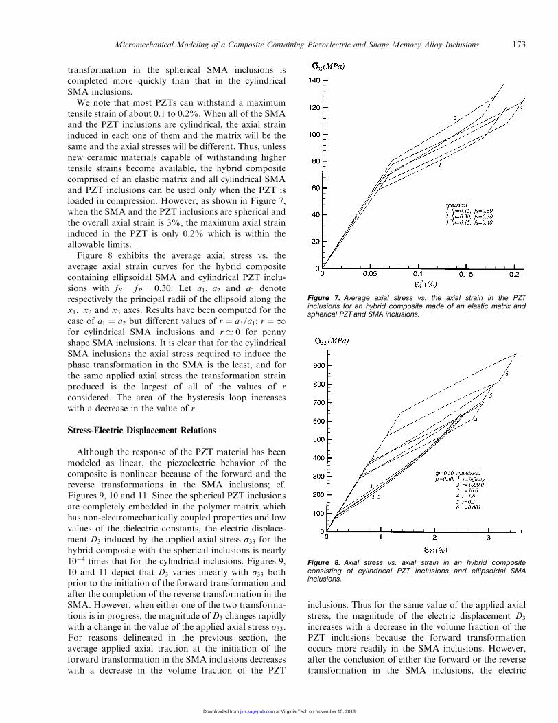
transformation in the spherical SMA inclusions iscompleted more quickly than that in the cylindricalSMA inclusions.We note that most PZTs can withstand a maximum
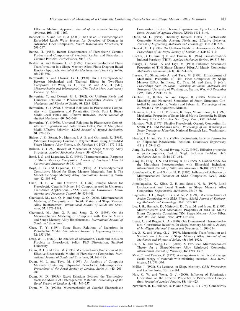
tensile strain of about 0.1 to 0.2%. When all of the SMAand the PZT inclusions are cylindrical, the axial straininduced in each one of them and the matrix will be thesame and the axial stresses will be different. Thus, unlessnew ceramic materials capable of withstanding highertensile strains become available, the hybrid compositecomprised of an elastic matrix and all cylindrical SMAand PZT inclusions can be used only when the PZT isloaded in compression. However, as shown in Figure 7,when the SMA and the PZT inclusions are spherical andthe overall axial strain is 3%, the maximum axial straininduced in the PZT is only 0.2% which is within theallowable limits.Figure 8 exhibits the average axial stress vs. the
average axial strain curves for the hybrid compositecontaining ellipsoidal SMA and cylindrical PZT inclu-sions with fS ¼ fP ¼ 0:30. Let a1, a2 and a3 denoterespectively the principal radii of the ellipsoid along thex1, x2 and x3 axes. Results have been computed for thecase of a1 ¼ a2 but different values of r ¼ a3=a1; r ¼ 1
for cylindrical SMA inclusions and r ’ 0 for pennyshape SMA inclusions. It is clear that for the cylindricalSMA inclusions the axial stress required to induce thephase transformation in the SMA is the least, and forthe same applied axial stress the transformation strainproduced is the largest of all of the values of rconsidered. The area of the hysteresis loop increaseswith a decrease in the value of r.
Stress-Electric Displacement Relations
Although the response of the PZT material has beenmodeled as linear, the piezoelectric behavior of thecomposite is nonlinear because of the forward and thereverse transformations in the SMA inclusions; cf.Figures 9, 10 and 11. Since the spherical PZT inclusionsare completely embedded in the polymer matrix whichhas non-electromechanically coupled properties and lowvalues of the dielectric constants, the electric displace-ment D3 induced by the applied axial stress �33 for thehybrid composite with the spherical inclusions is nearly10�4 times that for the cylindrical inclusions. Figures 9,10 and 11 depict that D3 varies linearly with �33 bothprior to the initiation of the forward transformation andafter the completion of the reverse transformation in theSMA. However, when either one of the two transforma-tions is in progress, the magnitude of D3 changes rapidlywith a change in the value of the applied axial stress �33.For reasons delineated in the previous section, theaverage applied axial traction at the initiation of theforward transformation in the SMA inclusions decreaseswith a decrease in the volume fraction of the PZT
inclusions. Thus for the same value of the applied axialstress, the magnitude of the electric displacement D3
increases with a decrease in the volume fraction of thePZT inclusions because the forward transformationoccurs more readily in the SMA inclusions. However,after the conclusion of either the forward or the reversetransformation in the SMA inclusions, the electric
Figure 7. Average axial stress vs. the axial strain in the PZTinclusions for an hybrid composite made of an elastic matrix andspherical PZT and SMA inclusions.
Figure 8. Axial stress vs. axial strain in an hybrid compositeconsisting of cylindrical PZT inclusions and ellipsoidal SMAinclusions.
Micromechanical Modeling of a Composite Containing Piezoelectric and Shape Memory Alloy Inclusions 173
at Virginia Tech on November 15, 2013jim.sagepub.comDownloaded from

displacement of the hybrid composite decreases with adecrease in the volume fraction of the PZT inclusions.Said differently, the phase transformation in the SMAinclusions enhances the electromechanical couplingproperties of the composite. For the same volumefraction of the PZT inclusions and the applied axialstress, the magnitude of the axial electric displacement
decreases with an increase in the volume fraction of theSMA inclusions.
We have plotted in Figure 11 the axial stress vs. theaxial electric displacement for the case of the cylindricalPZT and the ellipsoidal SMA inclusions. A comparisonof these results with the curve 2 of Figure 9 reveals thatfor the cylindrical SMA inclusions the axial stress for thesame value of the axial electric displacement is the least.The axial stress required to induce the same axial electricdisplacement increases with a decrease in the value ofthe aspect ratio r.
Effect of the Applied Electric Field
For the case of the spherical PZT inclusions com-pletely embedded in a non-electromechanically coupledpolymer matrix with low values of the dielectric con-stants, the electrical field applied to the hybridcomposite to induce a phase transformation in theSMA inclusions is very large. Thus we discuss only thecase of the cylindrical PZT inclusions for which Figures12 and 13 depict the relationship between the appliedaxial electric field E3 and the induced axial strain �33.Both prior to the initiation and after the conclusion ofthe phase transformation in the SMA, �33 varies linearlywith E3, and, for a fixed value of E3, the macroscopicaxial strain �33 increases with an increase in the volumefraction of the PZT inclusions. This is because theaxial strain is induced only due to the electro-mechanical coupling properties of the PZT inclusions.The applied electric field at the initiation of the forward
Figure 10. Axial stress vs. axial electric displacement for a three-phase composite consisting of a polymeric matrix and sphericalSMA and PZT inclusions.
Figure 11. Axial stress vs. axial electric displacement for a three-phase composite consisting of a polymeric matrix, cylindrical PZTand ellipsoidal SMA inclusions with fS ¼ fP ¼ 0:3.
Figure 9. Axial stress vs. axial electric displacement for a three-phase composite consisting of a polymeric matrix and cylindricalSMA and PZT inclusions.
174 B. JIANG AND R. C. BATRA
at Virginia Tech on November 15, 2013jim.sagepub.comDownloaded from

transformation in the SMA decreases with an increase inthe volume fraction of the PZT inclusions, and increaseswith an increase in the volume fraction of the SMAinclusions. However, as the phase transformation in theSMA progresses, the transformation strain is muchlarger than the strain induced by the applied electric
field in a pure PZT material and the relation betweenE3 and �33 for the three-phase composite is nonlinear.Results depicted in Figure 13 suggest that for thecylindrical SMA inclusions, the value of the axialelectric field at the initiation of the phase transformationin the SMA is the lowest. The area of the ‘‘hysteresis
Figure 12. Axial electric field vs. axial strain for a three-phasecomposite consisting of a polymeric matrix and cylindrical SMA andPZT inclusions.
Figure 13. Axial electric field vs. axial strain for a three-phasecomposite made of a polymeric matrix, cylindrical PZT inclusionsand ellipsoidal SMA inclusions with fS ¼ fP ¼ 0:3.
Figure 14. Axial electric field vs. axial electric displacement in athree-phase composite consisting of a polymeric matrix andcylindrical SMA and PZT inclusions.
Figure 15. Axial electric field vs. axial electric displacement in athree-phase composite made of a polymeric matrix, cylindrical PZTinclusions, and ellipsoidal SMA inclusions with fS ¼ fP ¼ 0:3.
Micromechanical Modeling of a Composite Containing Piezoelectric and Shape Memory Alloy Inclusions 175
at Virginia Tech on November 15, 2013jim.sagepub.comDownloaded from

loop’’ does not vary monotonically as the value of theaspect ratio, r, is decreased from 1 to 10�3, i.e., theshape of the SMA inclusions is changed from cylindricalto penny shape.Figures 14 and 15 depict the variation of the axial
electric displacement D3 with the applied axial electricfield E3. The effect of the phase transformation in theSMA inclusions is much less noticeable on these curves.The magnitude of the electric displacement in the hybridcomposite increases with an increase in the volumefraction of the PZT inclusions.Recalling that the dielectric strength of a typical PZT
is about 2MV/m, results plotted in Figures 12 and 13suggest that it may not be possible to induce largeactuation strains just by applying an electric field acrossthe faces of a patch made of the hybrid composite. The
consideration of the electric heat generated by theelectric current should facilitate the initiation of thephase transformation in the SMA and will reducesomewhat the required electric field.
Tabulated Values
In Tables 2 through 7 we have listed the computedvalues of the effective electromechanical moduli of the3-phase composite with the x3-axis aligned along thepolarization axis of the PZT inclusions. Values listed inTables 2, 3 and 4 assume that all of the SMA inclusionsare in the austenite phase, and those in Tables 5, 6 and 7are for the case of the SMA inclusions in the martensitephase. It is clear from these results that the effectiveelectroelastic moduli are symmetric when all of the
Table 2. Values of effective moduli for the 3-phase composite made of polymeric matrix, and cylindrical PZTand SMA inclusions. The SMA material is modeled as austenite.
fS ¼ 0:15 fS ¼ 0:30 fS ¼ 0:40
fP ¼ 0:15 fP ¼ 0:30 fP ¼ 0:40 fP ¼ 0:15 fP ¼ 0:30 fP ¼ 0:40 fP ¼ 0:15 fP ¼ 0:30 fP ¼ 0:40
�CC1111 (GPa) 12.20 15.81 19.36 15.77 21.63 28.10 19.27 28.04 39.09�CC1122 (GPa) 6.40 8.09 9.76 8.18 11.00 14.16 9.96 14.31 19.93�CC1133 (GPa) 6.59 8.27 9.92 8.67 11.54 14.72 10.72 15.18 20.84�CC3333 (GPa) 34.00 50.16 61.28 44.92 61.92 74.10 52.72 70.86 84.78�CC1212 (GPa) 2.90 3.86 4.80 3.80 5.31 6.97 4.66 6.86 9.58�CC1313 (GPa) 3.13 4.31 5.47 4.19 6.02 8.02 5.19 7.82 11.04�ee311 (C/m2) �6:60� 10�2 �0:163 �0:259 �8:19� 10�2 �0:215 �0:363 �9:76� 10�2 �0:273 �0:496�ee333 (C/m2) 2.98 5.94 7.89 2.97 5.90 7.81 2.95 5.85 7.72�ee131 (C/m2) 1:02� 10�3 2:98� 10�3 5:34� 10�3 1:08� 10�3 3:24� 10�3 6:02� 10�3 1:16� 10�3 3:62� 10�3 7:09� 10�3
�kk11=k0 3.99 5.39 6.63 2.95 3.99 4.87 2.40 3.26 3.98�kk33=k0 194.66 385.79 513.08 194.05 385.12 512.29 193.64 384.64 511.66���11 (MPa/�C) 1.06 1.09 1.12 1.12 1.18 1.24 1.17 1.27 1.39���33 (MPa/�C) 1.10 1.09 1.09 1.22 1.23 1.25 1.32 1.35 1.42�pp1 (C/m2 �C) 0.00 0.00 0.00 0.00 0.00 0.00 0.00 0.00 0.00�pp3 (C/m2 �C) 2:76� 10�4 5:53� 10�4 7:37� 10�4 2:76� 10�4 5:54� 10�4 7:39� 10�4 2:77� 10�4 5:547� 10�4 7:416� 10�4
k0 ¼ 8:85� 10�12 pF/m
Table 3. Values of effective moduli for the 3-phase composite made of a polymeric matrix, and spherical PZTand SMA inclusions. The SMA material is modeled as austenite.
fS ¼ 0:15 fS ¼ 0:30 fS ¼ 0:40
fP ¼ 0:15 fP ¼ 0:30 fP ¼ 0:40 fP ¼ 0:15 fP ¼ 0:30 fP ¼ 0:40 fP ¼ 0:15 fP ¼ 0:30 fP ¼ 0:40
�CC1111 (GPa) 12.94 17.16 21.27 17.07 23.08 31.10 21.07 30.96 43.10�CC1122 (GPa) 6.53 8.33 10.09 8.44 11.43 14.77 10.34 14.95 20.85�CC1133 (GPa) 6.52 8.28 10.01 8.41 11.36 14.62 10.31 14.84 20.61�CC3333 (GPa) 12.98 17.27 21.48 17.13 23.98 31.47 21.14 31.23 43.73�CC1212 (GPa) 3.20 4.42 5.59 4.32 6.18 8.17 5.36 8.01 11.13�CC1313 (GPa) 3.23 4.49 5.73 4.35 6.30 8.42 5.41 8.19 11.54�ee311 (C/m2) �6:23� 10�4 �1:83� 10�3 �3:31� 10�3 �6:87� 10�4 �2:08� 10�3 �3:88� 10�3 �7:49� 10�4 �2:34� 10�3 �4:54� 10�3
�ee333 (C/m2) 2:50� 10�3 7:37� 10�3 1:34� 10�2 2:81� 10�3 8:61� 10�3 1:63� 10�2 3:13� 10�3 1:00� 10�2 1:996� 10�2
�ee131 (C/m2) 1:78� 10�3 5:25� 10�3 9:52� 10�3 1:99� 10�3 6:10� 10�3 1:15� 10�3 2:21� 10�3 7:05� 10�3 1:399� 10�2
�kk11=k0 4.96 7.43 9.69 3.98 6.075 7.93 3.41 5.296 6.936�kk33=k0 4.96 7.44 9.70 3.99 6.082 7.94 3.42 5.301 6.945���11 (MPa/�C) 1.07 1.12 1.17 1.14 1.22 1.31 1.20 1.324 1.479���33 (MPa/�C) 1.01 0.975 0.94 1.07 1.03 0.997 1.12 1.096 1.077�pp1 (C/m2 �C) 0.00 0.00 0.00 0.00 0.00 0.00 0.00 0.00 0.00�pp3 (C/m2 �C) 2:08� 10�6 4:99� 10�6 7:68� 10�6 1:92� 10�6 4:56� 10�6 6:95� 10�6 1:83� 10�6 4:32� 10�6 6:559� 10�6
176 B. JIANG AND R. C. BATRA
at Virginia Tech on November 15, 2013jim.sagepub.comDownloaded from

inclusions are of the same shape, and do not retain thesymmetry properties when inclusions are of differentshapes. This asymmetry in the material moduli comesfrom the use of the mean field theory. However, whenan energy equivalent method is used to derive thematerial properties, the effective material moduli aresymmetric even when inclusions are of different shapes.When a phase transformation occurs in the SMA phase,approximate values of the effective moduli can beobtained by using the rule of mixtures. We hope thatthe values provided in these tables will enable research-ers in the field to analyze other problems for the 3-phasecomposite and explore their use as sensors andactuators.
Remarks
The heat generated by the electric field and thehysteresis exhibited by the SMA have been neglected.Also, creep effects in the epoxy matrix have beenignored. One way to account for all these effects is tonumerically solve an initial-boundary-value problemwhich is computationally expensive.
CONCLUSIONS
Based on the mean field theory and the Mori–Tanakamethod, we have derived macroscopic constitutive
Table 5. Values of effective moduli for the 3-phase composite made of a polymeric matrix, and cylindrical PZTand SMA inclusions. The SMA material is modeled as martensite.
fS ¼ 0:15 fS ¼ 0:30 fS ¼ 0:40
fP ¼ 0:15 fP ¼ 0:30 fP ¼ 0:40 fP ¼ 0:15 fP ¼ 0:30 fP ¼ 0:40 fP ¼ 0:15 fP ¼ 0:30 fP ¼ 0:40
�CC1111 (GPa) 11.846 15.275 18.605 14.739 19.877 25.363 17.398 24.517 32.888�CC1122 (GPa) 6.308 7.952 9.558 7.887 10.492 13.332 9.393 13.184 17.809�CC1133 (GPa) 6.425 8.026 9.585 8.180 10.725 13.462 9.814 13.495 17.879�CC3333 (GPa) 27.771 43.890 54.947 32.360 49.143 61.014 35.785 53.378 66.409�CC1212 (GPa) 2.769 3.661 4.523 3.426 4.692 6.015 4.002 5.667 7.539�CC1313 (GPa) 2.954 4.039 5.088 3.692 5.195 6.756 4.327 6.258 8.402�ee311 (C/m2) �6:464� 10�2 �0:1594 �0:252 �7:793� 10�2 �0:202 �0:335 �9:030� 10�2 �0:245 �0:430�ee333 (C/m2) 2.979 5.939 7.894 2.969 5.907 7.833 2.959 5.874 7.763�ee131 (C/m2) 9:854� 10�4 2:845� 10�3 5:066� 10�3 9:901� 10�4 2:898� 10�3 5:247� 10�3 1:016� 10�3 3:035� 10�3 5:632� 10�3
�kk11=k0 3.993 5.393 6.635 2.951 3.987 4.867 2.396 3.262 3.982�kk33=k0 194.661 385.794 513.094 194.052 385.137 512.344 193.643 384.679 511.774���11 (MPa/�C) 1.018 1.038 1.057 1.014 1.038 1.065 1.011 1.039 1.073���33 (MPa/�C) 0.983 0.970 0.964 0.9766 0.966 0.9658 0.971 0.964 0.969�pp1 (C/m2 �C) 0.00 0.00 0.00 0.00 0.00 0.00 0.00 0.00 0.00�pp3 (C/m2 �C) 2:759� 10�4 5:520� 10�4 7:363� 10�4 2:758� 10�4 5:520� 10�4 7:364� 10�4 2:758� 10�4 5:520� 10�4 7:365� 10�4
Table 4. Values of effective moduli for the 3-phase composite made of a polymeric matrix, and cylindrical PZT andspherical SMA inclusions. The SMA material is modeled as austenite.
fS ¼ 0:15 fS ¼ 0:30 fS ¼ 0:40
fP ¼ 0:15 fP ¼ 0:30 fP ¼ 0:40 fP ¼ 0:15 fP ¼ 0:30 fP ¼ 0:40 fP ¼ 0:15 fP ¼ 0:30 fP ¼ 0:40
�CC1111 (GPa) 12.55 16.23 19.84 16.61 22.65 29.28 20.54 29.60 40.89�CC1122 (GPa) 6.47 8.18 9.86 8.36 11.23 14.44 10.25 14.69 20.40�CC1133 (GPa) 6.43 8.07 9.68 8.29 11.04 14.07 10.15 14.35 19.63�CC3311 (GPa) 6.52 8.30 10.04 8.56 11.73 15.23 10.62 15.66 22.00�CC3333 (GPa) 28.14 46.57 59.20 34.45 56.77 72.50 40.22 66.39 85.69�CC1212 (GPa) 3.04 4.03 4.99 4.126 5.71 7.42 5.15 7.45 10.24�CC1313 (GPA) 3.17 4.36 5.52 4.290 6.14 8.16 5.34 7.99 11.23�ee311 (C/m2) �4:65� 10�2 �0.115 �0.183 �2:55� 10�2 �6:70� 10�2 �0.113 3:30� 10�3 9:19� 10�3 1:66� 10�2
�ee333 (C/m2) 3.44 6.86 9.135 4.05 8.10 10.78 4.61 9.21 12.29�ee131 (C/m2Þ 1:06� 10�3 3:13� 10�3 5:70� 10�3 1:14� 10�3 3:50� 10�3 6:63� 10�3 1:23� 10�3 3:94� 10�3 7:85� 10�3
�kk11=k0 4.32 5.91 7.37 3.39 4.69 5.84 2.85 3.98 4.97�kk33=k0 181.09 358.93 477.41 168.77 335.06 445.86 161.42 320.85 427.14���11 (MPa/�C) 1.06 1.09 1.12 1.12 1.18 1.24 1.18 1.28 1.39���33 (MPa/�C) 1.047 1.06 1.076 1.13 1.19 1.25 1.21 1.33 1.45�pp1 (C/m2 �C) 0 0 0 0 0 0 0 0 0�pp3 (C/m2 � C) 2:719� 10�4 5:44� 10�4 7:26� 10�4 2:66� 10�4 5:33� 10�4 7:11� 10�4 2:61� 10�4 5:23� 10�4 6:79� 10�4
Micromechanical Modeling of a Composite Containing Piezoelectric and Shape Memory Alloy Inclusions 177
at Virginia Tech on November 15, 2013jim.sagepub.comDownloaded from

relations for a three phase composite made of PZT andSMA inclusions embedded in a non-electromechanicallycoupled polymer matrix. All of the PZT inclusionsconsidered are identical in shape and have the same axisof polarization. Similarly, all of the SMA inclusionshave the same shape. However, the PZT and SMAinclusions may have different shapes. Because of thetransformation strains induced in the SMA inclusions,the hybrid composite exhibits a nonlinear behavior eventhough the matrix and the PZT are modeled as linearmaterials. It is found that the cylindrical inclusions arebetter than the spherical ones in the sense that theapplied electric field at the instant of the initiation ofthe forward transformation in the SMA inclusions isconsiderably lower for the cylindrical inclusions thanthat for the spherical inclusions. However, for sphericalinclusions, for the same axial stress, the axial strain
induced in the PZTs is considerably less than that incylindrical inclusions; the latter equals the overall axialstrain. Also, the phase transformation in the SMAinclusions is found to enhance the electromechanicalcoupling properties of the 3-phase composite. Thehybrid composite exhibits pyroelectric effect even ifnone of its constituents is pyroelectric; a similar resultwas obtained earlier by Dunn (1993b) for a piezo-composite.
A hybrid composite with about 15% PZT and 30%SMA spherical inclusions can make an effective straingauge since about 3% axial strain is produced byonly100MPa axial stress.
The macroscopic properties of the hybrid compositeprovided herein should facilitate the solution ofboundary-value problems and the design of such3-phase sensors and actuators.
Table 7. Values of effective moduli for the 3-phase composite made of a polymeric matrix, and cylindrical PZT andspherical SMA inclusions. The SMA material is modeled as martensite.
fS ¼ 0:15 fS ¼ 0:30 fS ¼ 0:40
fP ¼ 0:15 fP ¼ 0:30 fP ¼ 0:40 fP ¼ 0:15 fP ¼ 0:30 fP ¼ 0:40 fP ¼ 0:15 fP ¼ 0:30 fP ¼ 0:40
�CC1111 (GPa) 12.07 15.51 18.85 15.22 20.37 25.82 18.05 25.14 33.32�CC1122 (GPa) 6.37 8.02 9.64 8.03 10.66 13.50 9.61 13.41 17.99�CC1133 (GPa) 6.32 7.89 9.41 7.94 10.38 12.97 9.46 12.93 16.99�CC3311 (GPa) 6.50 8.35 10.13 8.44 11.68 15.12 10.31 15.21 20.95�CC3333 (GPa) 27.31 45.27 57.59 32.21 53.23 68.05 36.44 60.34 77.85�CC1212 (GPa) 2.85 3.75 4.61 3.59 4.86 6.16 4.22 5.86 7.66�CC1313 (GPa) 2.98 4.06 5.11 3.74 5.24 6.79 4.39 6.31 8.42�ee311 (C/m2) �2:63� 10�2 �6:48� 10�2 �0:102 2:55� 10�2 6:58� 10�2 0.107 8:33� 10�2 0.225 0.39�ee333 (C/m2) 3.35 6.69 8.91 3.81 7.63 10.19 4.21 8.449 11.32�ee131ðC=m2Þ 1:02� 10�3 2:99� 10�3 5:39� 10�3 1:04� 10�3 3:12� 10�3 5:74� 10�3 1:07� 10�3 3:282� 10�3 6:20� 10�3
�kk11=k0 4.32 5.91 7.37 3.39 4.69 5.84 2.85 3.99 4.97�kk33=k0 181.10 359.00 477.54 168.80 335.21 446.21 161.47 321.10 427.70���11 (MPa/�C) 1.02 1.04 1.06 1.014 1.039 1.065 1.011 1.04 1.074���33 (MPa/�C) 0.98 0.97 0.96 0.976 0.962 0.961 0.970 0.957 0.962�pp1 (C/m2 �C) 0 0 0 0 0 0 0 0 0�pp3 (C/m2 �C) 2:76� 10�4 5:53� 10�4 7:37� 10�4 2:77� 10�4 5:54� 10�4 7:383� 10�4 2:77� 10�4 5:55� 10�4 7:39� 10�4
Table 6. Values of effective moduli for the 3-phase composite made of a polymeric matrix,and spherical PZT and SMA inclusions. The SMA material is modeled as martensite.
fS ¼ 0:15 fS ¼ 0:30 fS ¼ 0:40
fP ¼ 0:15 fP ¼ 0:30 fP ¼ 0:40 fP ¼ 0:15 fP ¼ 0:30 fP ¼ 0:40 fP ¼ 0:15 fP ¼ 0:30 fP ¼ 0:40
�CC1111 (GPa) 12.452 16.427 20.247 15.666 21.467 27.541 18.567 26.421 35.385�CC1122 (GPa) 6.434 8.176 9.875 8.117 10.869 13.850 9.714 13.696 18.491�CC1133 (GPa) 6.420 8.136 9.803 8.099 10.814 13.744 9.693 13.626 18.350�CC3333 (GPa) 12.485 16.527 20.430 15.711 21.612 27.827 18.624 26.615 35.797�CC1212 (GPa) 3.009 4.125 5.186 3.775 5.299 6.846 4.426 6.363 8.447�CC1313 (GPa) 3.032 4.193 5.310 3.805 5.395 7.034 4.464 6.489 8.710
�ee311 (C/m2) �5:936� 10�4 �1:723� 10�3 �3:083� 10�3 �6:116� 10�4 �1:792� 10�3 �3:233� 10�3 �6:277� 10�4 �1:851� 10�3 �3:353� 10�3
�ee333 (C/m2) 2:416� 10�3 7:062� 10�3 1:272� 10�2 2:590� 10�3 7:746� 10�3 1:429� 10�2 2:761� 10�3 8:468� 10�3 1:608� 10�2
�ee131 (C/m2) 1:715� 10�3 5:008� 10�3 9:009� 10�3 1:825� 103 5:438� 10�3 9:996� 10�3 1:931� 10�3 5:884� 10�3 1:109� 10�2
�kk11=k0 4.955 7.434 9.689 3.985 6.076 7.928 3.415 5.296 6.936�kk33=k0 4.958 7.441 9.702 3.987 6.082 7.939 3.417 5.301 6.946���11 (MPa/�C) 1.029 1.066 1.100 1.027 1.070 1.115 1.025 1.074 1.129���33 (MPa/�C) 0.972 0.926 0.881 0.962 0.904 0.845 0.952 0.884 0.809
�pp1 (C/m2 �C) 0.00 0.00 0.00 0.00 0.00 0.00 0.00 0.00 0.00
�pp3 (C/m2 �C) 2:078� 10�6 4:990� 10�6 7:683� 10�6 1:924� 10�6 4:562� 10�6 6:951� 10�6 1:834� 10�6 4:320� 10�6 6:548� 10�6
178 B. JIANG AND R. C. BATRA
at Virginia Tech on November 15, 2013jim.sagepub.comDownloaded from

APPENDIX
Eshelby Tensors for Thermoelectroelastic
Deformations
Consider an ellipsoidal piezoelectric (PZT) inclusionwith a uniform eigenstrain ��ij and a uniform eigen-electric field E�
i embedded in an infinite nonpiezoelectricbut pyroelectric matrix. The constitutive behavior of thePZT inclusion is described by Equation (2), with �kl andEk replaced by �kl � ��kl and Ek � E�
k respectively, andthat of the matrix by Equation (1). In terms of thecharacteristic function hðxÞ defined as
hðxÞ ¼1 when x 2 �P,0 when x =2 �P,
�ðA1Þ
constitutive relations for the PZT and the matrix can bewritten as
�ij ¼ CMijkluk, l � �Mij � þ ��ijhðxÞ,
Di ¼ �kMij �, j þ pMi � þ DDihðxÞ,ðA2Þ
where
��ij ¼ C0ijkluk, l � �0ij� þ eImijð�,m þ E�
mÞ � CIijkl�
�kl ,
DDi ¼ �k0im�,m þ p0i � þ eIijkðuj, k � ��jkÞ � kIimE�m,
�ij ¼ ðui, j þ uj, iÞ=2, Ei ¼ ��, i,
C0ijkl ¼ CI
ijkl � CMijkl, k0ij ¼ kIij � kMij , �0ij ¼ �Iij � �Mij ,
p0i ¼ pIi � pMi : ðA3Þ
Here u is the mechanical displacement, � the electricpotential, and �, i ¼ @�=@xi, Ei ¼ ��, i, and the super-script I refers to the PZT inclusion.Henceforth we assume that the temperature is uni-
form throughout the body. In the absence of body forcesand free charges, static electroelastic deformations of thePZT and the matrix are governed by
�ij, j ¼ 0, Di, i ¼ 0: ðA4Þ
Substituting from (A2) into (A4) and recalling that thetemperature � is uniform, we arrive at
CMijkluk, lj ¼ �½��ijhðxÞ�, j, kMij �, ji ¼ ½DDihðxÞ�, i: ðA5Þ
The terms on the right-hand sides of Equations (A5)1and (A5)2 can be regarded as body forces anddistributed charges applied to the matrix. FollowingJiang et al. (1997, 1999), the concentration strain eI andthe concentration electric field EI in the PZT inclusioncan be obtained from
�Iij ¼ H1ijkl�
0kl þH2
ijkE0k þ F1
ij�0 þ S1
ijkl��kl þ S2
ijkE�k ,
E1i ¼ H3
ijk�0jk þH4
ijE0j þ F2
i �0 þ S3
ijk��jk þ S4
ijE�j , ðA6Þ
where
H1ijkl ¼ XijmnAmnkl, H2
ijk ¼ Xijmn�mnpBpk,
H3ijk ¼ �YimmnpAnpjk, H4
ij ¼ YimBmj,
S1ijkl ¼ Iijkl � XijmnðImnkl � �mnklÞ,
S2ijk ¼ �Xijmn�mnpð�pk � pkÞ,
S3imn ¼ YijjklðIklmn � �klmnÞ,
S4ij ¼ �ij � Yilð�lj � ljÞ,
F1ij ¼ �Xijmnð�mn þ �mnp�pÞ,
F2i ¼ Yijðjkl�kl � �jÞ,
ðA7Þ
are the thermoelectroelastic Eshelby tensors. In Equa-tions (A7),
Aijkl ¼ ½Iijkl þ SuijmnðC
MmnpqÞ
�1C0pqij �
�1,
Bij ¼ ½�ij þ S�imðk
MmnÞ
�1k0nj ��1,
�ijk ¼ ZijmneIkmn, ijk ¼ zime
Imjk, �ijkl ¼ ZijmnC
Imnkl,
ij ¼ zimkImj, �ij ¼ �Zijmn�
0mn, �i ¼ zijp
0j ,
Xijkl ¼ ðIijkl þ �ijmmklÞ�1, Yij ¼ ð�ij þ imn�mnjÞ
�1,
Zijkl ¼ AijmnSumnpqðC
MpqklÞ
�1, zij ¼ BimS�mnðk
Mnj Þ
�1
Iijkl ¼1
2ð�ik�jl þ �il�jkÞ,
ðA8Þ
where Su and S� are respectively the Eshelby tensors forthe elastic and the dielectric inclusions whose shapes andorientations are the same as those of the PZT inclusionsconsidered herein. When thermal effects are notconsidered, i.e., kP ¼ 0 and pP ¼ 0, expressions (A7)for the thermoelectroelastic Eshelby tensors reduce tothose derived by Jiang et al. (1997). For a nonpiezo-electric inclusion, eP ¼ 0, and expressions (A7) simplifyto those of Benveniste and Dvorak (1990). In the spaceof stress and electric field, we have
�Iij ¼ H5
ijkl�0kl þH6
ijkE0k þ F3
ij�0 þ S5
ijkl��kl þ S6
ijkE�k ,
EIi ¼ H7
ikl�0kl þH4
ijE0j þ F2
i �0 þ S3
ikl��kl þ S4
ijE�j ,
ðA9Þ
where
H5ijkl ¼ ½CI
ijmnH1mnpq � eImijH
3mpq�ðC
MpqklÞ
�1,
H6ijk ¼ CI
ijmnH2mnk � eImijH
4mk,
H7ijk ¼ H3
imnðCMmnjkÞ
�1,
F3ij ¼ CI
ijmnF1mn � eImijF
2m � �Iij ,
S5ijkl ¼ CI
ijmnðS1mnkl � ImnklÞ � eImijS
3mkl ,
S6ijk ¼ CI
ijmnS2mnk � eImijðS
4mk � �mkÞ:
ðA10Þ
Micromechanical Modeling of a Composite Containing Piezoelectric and Shape Memory Alloy Inclusions 179
at Virginia Tech on November 15, 2013jim.sagepub.comDownloaded from

For the hybrid composite studied herein, only the SMAinclusion has an eigenstrain, and there is no eigen-electric field in any phase.
Mori–Tanaka Approximation for
Thermoelectroelastic Concentration Tensors
The Mori–Tanaka method approximately accountsfor the interaction among inclusions embedded in amatrix. This method gives the following values of theaverage strain and the average electric field in thematrix.
���Mij ¼ LMijkl�
0kl þNM
ijkE0k þ RM
ij �0 þ ���Mij ,
�EEMi ¼ PM
ijk�0jk þQM
ij E0j þ JM
i �0 þ E��Mi ,
ðA11Þ
where
LMijkl ¼ H1
ijkl �H2ijmðH
4mnÞ
�1H3
nkl
h i�1
,
NMijk ¼ �LM
ijmnH2mnpðH
4pkÞ
�1,
PMijk ¼ �ðH4
im�1H3
mpqLMpqjk,
QMij ¼ ðH4
im�1 �mj �H3
mklNMklj
,
RMij ¼ � LM
ijklF1kl þNM
ijkF2k
,
JMi ¼ � PM
imnF1mn þQM
imF2m
� �,
���Mij ¼ �fSLMijkl S
1Sklmn�
trmn
� �S,
E��Mi ¼ �fSP
Mikl S
1Sklmn�
trmn
� �S,
H1ijkl ¼ Iijkl �
Xr¼S,P
fr Iijkl � H1rijkl
D Er
h i,
H2ijk ¼ fP H2P
ijk
D EP,
H3Pijk ¼ fP H3P
ijk
D EP
H4ij ¼ �ij �
Xr¼S,P
fr �ij � H4rij
D Er
h i
F 1ij ¼
Xr¼S,P
fr F1rij
D Er, F 2
i ¼Xr¼S,P
fr F2ri
� �r: ðA12Þ
The constraint strain and the constraint electric field inthe PZT inclusion ðr ¼ PÞ and the SMA inclusionðr ¼ SÞ are given by
���rij ¼ Lrijkl�
0kl þNr
ijkE0k þ Rr
ij�0 þ ���rij ,
�EEri ¼ Pr
ijk�0jk þQr
ijE0j þ Jr
i �0 þ E��r
i ,
where
Lrijkl ¼ H1r
ijmnLMmnkl þH2r
ijmPMmkl ,
Nrijk ¼ H1r
ijmnNMmnk þH2r
ijmQMmk,
Prijk ¼ H3r
imnLMmnjk þH4r
imPMmjk,
Qrij ¼ H3r
imnNMmnj þH4r
imQMmj,
Rrij ¼ F1r
ij þH1rijmnR
Mmn þH2r
ijmJMm ,
Jri ¼ F2r
i þH3rimnR
Mmn þH4r
imJMm ,
���rij ¼ S1rijmn�
�rmn þH1r
ijmn���Mmn þH2r
ijmE��Mm ,
E��ri ¼ H3r
imn���Mmn þH4r
imE��Mm ,
In the space of stress and electric field, we have
����ij ¼ L�
ijkl�0kl þN�
ijkE0k þ R�
ij�0 þ ����
ij ,
�EE�i ¼ P�
ikl�0kl þQ�
ijE0j þ J�
i �0 þ E���
i ,
where
L�ijkl ¼ H5
ijkl �H6ijmðH
4mnÞ
�1H7
nkl
h i�1
,
N�ijk ¼ �L�
ijmnH6mnpðH
4pkÞ
�1,
P�ijk ¼ �ðH4
im�1H7
mpqL�pqjk,
Q�ij ¼ ðH4
imÞ�1ð�mj �H7
mpqN�pqjÞ,
R�ij ¼ �ðL�
ijmnF3mn þN�
ijpF2pÞ,
J�i ¼ �ðP�
imnF3mn þQ�
imF2mÞ,
����ij ¼ �fSL
�ijkl S
5Sklmn�
trmn
� �S,
E���i ¼ �fSP
�ikl S
5Sklmn�
trmn
� �S,
H5ijkl ¼ Iijkl �
Xr¼S,P
fr Iijkl � H5rijkl
D Er
h i,
H6ijk ¼ fP H6P
ijk
D EP,
H7ijk ¼ fP H7P
ijk
D EP,
F 3ij ¼
Xr¼S,P
fr F3rij
D Er:
ACKNOWLEDGEMENT
This work was partially supported by the NSF grantCMS9713453 to Virginia Polytechnic Institute and StateUniversity.
REFERENCES
Armstrong, W. D. and Kino, H. (1995). Martensitic Transformationsin a TiNi Fiber Reinforced 6061 Aluminum Matrix Composite.Journal of Intelligent Material Systems and Structures, 6: 809–816.
Armstrong, W. D. (1996). A One-Dimensional Model of a ShapeMemory Alloy Fiber Reinforced Aluminum Metal Matrix Com-posite. Journal of Intelligent Material Systems and Structures,7: 448–454.
Avellaneda, M. and Swart, P. J. (1998). Calculating the Performanceof 1–3 Piezoelectric Composite for Hydrophone Applications: An
180 B. JIANG AND R. C. BATRA
at Virginia Tech on November 15, 2013jim.sagepub.comDownloaded from
Effective Medium Approach. Journal of the acoustic Society ofAmerica, 103: 1449–1467.
Badcock, R. A. and Birt, E. A. (2000). The Use of 0–3 PiezocompositeEmbedded Lamb Wave Sensors for Detection of Damage inAdvanced Fiber Composites. Smart Material and Structures, 9:291–297.
Banno, H. (1983). Recent Developments of Piezoelectric CeramicProducts and Composites of Synthetic Rubber and PiezoelectricCeramic Particles. Ferroelectrics, 50: 3–12.
Bekker, A. and Brinson, L. C. (1997). Temperature-Induced PhaseTransformation in a Shape Memory Alloy: Phase Diagram BasedKinetics Approach. Journal of the Mechanics and Physics of Solids,45: 949–988.
Benveniste, Y. and Dvorak, G. J. (1990). On a CorrespondenceBetween Mechanical and Thermal Effects in Two-PhaseComposites. In: Weng, G. J., Taya, M. and Abe, H. (eds.),Micromechanics and Inhomogeneity, The Toshio Mura AnniversaryVolume. pp. 65–81.
Benveniste, Y. and Dvorak, G. J. (1992). On Uniform Fields andUniversal Relations in Piezoelectric Composites. Journal of theMechanics and Physics of Solids, 40: 1295–1312.
Benveniste, Y. (1993a). Universal Relations in Piezoelectric Compo-sites with Eigenstress and Polarization Fields, Part I: BinaryMedia-Local Fields and Effective Behavior. ASME Journal ofApplied Mechanics, 60: 265–269.
Benveniste, Y. (1993b). Universal Relations in Piezoelectric Compo-sites with Eigenstress and Polarization Fields, Part II: MultiphaseMedia-Effective Behavior. ASME Journal of Applied Mechanics,60: 270–275.
Bidaux, J. E., Bernet, N., Manson, J. A. E. and Gotthardt, R. (1995).Vibration Frequency Control of Polymer Beam Using EmbeddedShape-Memory-Alloy Fibers. J. de. Physique IV, 5(C8): 1177–1182.
Birman, V. (1997). Review of Mechanics of Shape Memory AlloyStructures. Applied Mechanics Review, 50: 629–645.
Boyd, J. G. and Lagoudas, D. C. (1994). Thermomechanical Responseof Shape Memory Composites. Journal of Intelligent MaterialSystems and Structures, 5: 333–346.
Boyd, J. G. and Lagoudas, D. C. (1996). A ThermodynamicalConstitutive Model for Shape Memory Materials. Part I: TheMonolithic Shape Memory Alloy. International Journal of Plasti-city, 12: 805–842.
Chan, H. L. W. and Unsworth, J. (1989). Simple Model forPiezoelectric Ceramic/Polymer 1–3 Composites used in UltrasonicTransducer Applications. IEEE Trans. on Ultrasonics, Ferro-electrics and Frequency Control, 36: 434–441.
Cherkaoui, M., Sun, Q. P. and Song, G. Q. (2000). MicromechanicsModeling of Composite with Ductile Matrix and Shape MemoryAlloy Reinforcement. International Journal of Solids and Struc-tures, 37: 1577–1594.
Cherkaoui, M., Sun, Q. P. and Song, G. Q. (1998). On theMicromechanics Modeling of Composite with Ductile Matrixand Shape Memory Alloy Reinforcement. International Journal ofSolids and Structures.
Chen, T. Y. (1994). Some Exact Relations of Inclusions inPiezoelectric Media. International Journal of Engineering Science,32: 553–556.
Deeg, W. F., (1980). The Analysis of Dislocation, Crack and InclusionProblem in Piezoelectric Solids. PhD Dissertation, StanfordUniversity.
Dunn, D. L. and Taya, M. (1993). Micromechanics Predictions of theEffective Electroelastic Moduli of Piezoelectric Composites. Inter-national Journal of Solids and Structures, 30: 161–175.
Dunn, M. L. and Taya, M. (1993). An Analysis of CompositeMaterials Containing Ellipsoidal Piezoelectric Inhomogeneities.Proceedings of the Royal Society of London, Series A, 443: 265–287.
Dunn, M. D. (1993a). Exact Relations Between the Thermoelec-troelastic Moduli of Heterogeneous Materials. Proceedings of theRoyal Society of London A, 441: 549–557.
Dunn, M. D. (1993b). Micromechanics of Coupled Electroelastic
Composites: Effective Thermal Expansion and Pyroelectric Coeffi-cients. Journal of Applied Physics, 73(10): 5131–5140.
Dunn, M. L. (1994). Thermally Induced Fields in ElectroelasticComposite Materials: Average Fields and Effective Behavior.Journal of Engineering Materials and Technology, 116: 200–207.
Dvorak, G. J. (1990). On Uniform Fields in Heterogeneous Media.Proceedings of the Royal Society of London, A 431: 89–110.
Fischer, D. D., Sun, Q. P. and Tanaka, K. (1996). Transformation-Induced Plasticity (TRIP). Applied Mechanics Review, 49: 317–364.
Furuya, Y., Sasaki, A. and Taya, M. (1993). Enhanced MechanicalProperties of TiNi Shape Memory Fiber/Al Matrix Composite.Materials Transactions JIM, 34: 224–227.
Furuya, Y., Shimamoto A. and Taya, M. (1997). Enhancement ofMechanical Properties of TiNi Fiber Composites by ShapeMemory Effect. In: Inoue, K., Taya, M. and Shen, S. (eds.),Proceedings First US-Japan Workshop on Smart Materials andStructures. University of Washington, Seattle, WA, 4–5 December1995, TMS-AIME, 65–74.
Gabbert, U., Kreher, W. and Koppe, H. (1999). MathematicalModeling and Numerical Simulation of Smart Structures Con-trolled by Piezoelectric Wafers and Fibers. In: Proceedings of theEUROMAT ‘99 Conference, Munich.
Hamada, K., Lee, J. H., Mizuuchi, K. Taya, M. and Inoue, K. (1997).Mechanical Properties of Smart Metal Matrix Composite by ShapeMemory Effects. Mat. Res. Soc. Symp. Proc., 459: 143–148.
Harrison, W.B. (1976). Flexible Piezoelectric Organic Composites. In:Smith, P.L. and Pohanka (eds.), Proceedings of the Workshop onSonar Transducer Materials. National Research Lab, Washington,D.C., 257–268.
Hwang, J. H. and Yu, J. S. (1994). Electroelastic Eshelby Tensors foran Ellipsoidal Piezoelectric Inclusion. Composites Engineering,4(11): 1169–1182.
Jiang, B., Fang, D. N. and Hwang, K. C. (1997). Effective propertiesof piezocomposites, Part I: Single Inclusion Problem. ActaMechanica Sinica, 13(4): 347–354.
Jiang, B., Fang, D. N. and Hwang, K. C. (1999). A Unified Model forthe Multiphase Piezocomposites with Ellipsoidal Inclusions.International Journal of Solids and Structures, 36(18): 2707–2733.
Jonnalagadda, K. and Sottos, N. R. (1995). Influence of Adhesion onMicromechanical Behavior of SMA Composites. SPIE, 2442:143–151.
Jonnalagadda, K., Kline, G. E. and Sottos, N. R. (1997). LocalDisplacement and Local Transfer in Shape Memory AlloyComposites. Experimental Mechanics, 37: 78–86.
Lagoudas, D. C., Boyd, J. G. and Bo, Z. (1994). Micromechanics ofActive Composites with SMA Fibers. ASME Journal of Engineer-ing Materials and Technology, 116: 337–347.
Lee, J. H., Hamada, K., Miziuuchi, K., Taya, M. and Inoue, K. (1997).Microstructures and Mechanical Properties of 6061 Al MatrixSmart Composite Containing TiNi Shape Memory Alloy Fiber.Mat. Res. Soc. Symp. Proc., 459: 419–424.
Liang, C. and Rogers, C. A. (1990). One Dimensional Thermomecha-nical Constitutive Relations for Shape Memory Materials. Journalof Intelligent Material Systems and Structures, 1: 207–234.
Lu, Z. K. and Weng, G. J. (1997). Martensitic Transformation andStress-Strain Relations of Shape Memory Alloy. Journal of theMechanics and Physics of Solids, 45: 1905–1928.
Lu, Z. K. and Weng, G. J. (2000). A Two-Level MicromechanicalTheory for a Shape-Memory Alloy Reinforced Composite.International Journal of Plasticity, 16: 1289–1307.
Mori, T. and Tanaka, K. (1973). Average stress in matrix and averageelastic energy of materials with misfitting inclusion. Acta Metal-lurgica, 21: 571–574.
M �uuller, I. (1998). Six Lectures on Shape Memory. CRM Proceedingsand Lecture Notes, 13: 125–161.
Nan, C. W. and Weng, G. J. (2000). Influence of PolarizationOrientation on the Effective Properties of Piezoelectric Compo-sites. Journal of Applied Physics, 88: 416–423.
Newnham, R. E., Skinner, D. P. and Cross, L. E. (1978). Connectivity
Micromechanical Modeling of a Composite Containing Piezoelectric and Shape Memory Alloy Inclusions 181
at Virginia Tech on November 15, 2013jim.sagepub.comDownloaded from

and Piezoelectric-Pyroelectric Composites. Materials in Engineer-ing, 2: 93–106.
Newnham, R. E., Bowen, L. J., Klicker, K. A. and Cross, L. E.(1980).Composite Piezoelectric Transducers. Materials in Engineer-ing, 2: 93–106.
Patoor, E., Eberhardt, A. and Berveiller, M. (1988). Thermomecha-nical Behavior of Shape Memory Alloy. Archives of Mechanics, 40:775–794.
Pauer, L. A. (1973). Flexible Piezoelectric Material. IEEE Intl. Conv.Rec., 1–5.
Raniecki, B., Lexcellent, C. and Tanaka, K. (1992). ThermodynamicModels of Pseudoelastic Behavior of Shape Memory Alloys.Archives of Mechanics, 44: 261–284.
Schulgasser, K. (1992). Relationships Between the Effective Propertiesof Transversely Isotropic Piezoelectric Composites. Journal of theMechanics and Physics of Solids, 40(2): 473–479.
Smith, W. A. (1989). The Role of Piezocomposites in UltrasonicTransducers. Proceedings of the IEEE Ultrasonic Symposium,755–766.
Smith, W. A. and Auld, B. A. (1991). Modeling 1–3 Com-posite Piezoelectrics: Thickness-Mode Oscillations, IEEE Transac-tions on Ultrasonics, Ferroelectrics, and Frequency Control, 38:40–47.
Sottos, N. R., Kline, G. E., Qidwai, M. A. and Lagoudas, D. C.(1996). Analysis of Phase Transformation Fronts in SMAComposites. SPIE, 2715: 27–438.
Song, G. Q., Sun, Q. P. and Hwang, K. C. (22–25 April, 1997).Micromechanics Constitutive Modelling for Polycrystalline SMA.In: Proceedings of IUTAM Symposium Variation of Domains andFree-Boundary Problems in Solid Mechanics. Paris, France.
Song G. Q., Sun, Q. P. and Cherkaoui, C. (1999). Role ofMicrostructure in the Thermomechanical Behavior of SMAComposites. ASME Journal of Engineering Materials and Technol-ogy, 121: 86–92.
Stalmans, R., Delaey, L. and Van Humbeeck, J. (1997). Modelling ofAdaptive Composite Materials with Embedded Shape MemoryAlloy Wires. Mat. Res. Soc. Symp. Proc., 459: 119–130.
Sun, Q. P. and Hwang, K. C. (1993). Micromechanics Modelling forthe Constitutive Behavior of Polycrystalline Shape Memory Alloys:I. Derivation of General Relations, II. Study of the IndividualPhenomena. Journal of the Mechanics and Physics of Solids, 41:1–33.
Sun, G. J. and Sun, C. T. (1995). Bending of Shape Memory AlloyReinforced Composite Beam. Journal of Materials Sciences, 30:5750–5754.
Tanaka, K., Kobayashi, S. and Sato, Y. (1986). Thermomechanics ofTransformation Pseudoelasticity and Shape Memory Effect inAlloys. International Journal of Plasticity, 2: 59–72.
Taya, M., Shimamoto, A. and Furuya, Y. (1995). Design of SmartComposites Based on Shape Memory Effect. In: Poursartip, A. andStreet, K. (eds.), Proceedings ICCM-10. Whristler, BC, Canada,Vol. 275–282.
Wang, B. (1992). Three-dimensional Analysis of an EllipsoidalInclusion in a Piezoelectric Material. International Journal Solidsand Structures, 29: 293–308.
Yamada, Y., Taya, M. and Watanabe, R. (1993). Strengthening ofMetal Matrix Composite by Shape Memory Effect. MaterialsTransactions, JIM, 34: 254–260.
182 B. JIANG AND R. C. BATRA
at Virginia Tech on November 15, 2013jim.sagepub.comDownloaded from