journal of la lu factorization with partial pivoting for a ... · lu factorization with partial...
TRANSCRIPT
JOURNAL OF LATEX CLASS FILES, VOL. 6, NO. 1, JANUARY 2007 1
LU Factorization with Partial Pivotingfor a Multicore System with AcceleratorsJakub Kurzak, Member, IEEE, Piotr Luszczek, Member, IEEE,Mathieu Faverge, Member, IEEE,
and Jack Dongarra, Life Fellow, IEEE
Abstract—LU factorization with partial pivoting is a canonical numerical procedure and the main component of the High Performance Linpackbenchmark. This article presents an implementation of the algorithm for a hybrid, shared memory, system with standard CPU cores andGPU accelerators. The diXculty of implementing the algorithm for such a systems lies in the disproportion between the computatinal powerof the CPUs, compared to the GPUs, and in the meager bandwidth of the communication link between their memory systems. Additionalchallenge comes from the complexity of the memory-bound and synchronization-rich nature of the panel factorization component of the blockLU algorithm, imposed by the use of partial pivoting. The challenges are tackled with the use of a data layout geared towards complex memoryhierarchies, autotuning of GPU kernels, Vne grain parallelization of memory-bound CPU operations and dynamic scheduling of tasks to diUerentdevices. Performance in excess of one TeraFLOPS is achieved using four AMD Magny Cours CPUs and four NVIDIA Fermi GPUs.
Index Terms—Gaussian elimination, LU factorization, partial pivoting, multicore, manycore, GPU, accelerator
F
1 IntroductionThis paper presents an implementation of the canonicalformulation of the LU factorization, which relies on par-tial pivoting for numerical stability. It is equivalent to theDGETRF function from the LAPACK numerical library. Sincethe algorithm is coded in double precision, it can serve as thebasis for an implementation of the High Performance Lin-pack benchmark (HPL) [14]. The target platform is a systemcombining one CPU board with four 12-core CPUs and oneGPU board with four 14-core GPUs, for the total numberof 104 hybrid cores. Here GPU core means a device thatcan independently schedule instructions, which in NVIDIAnomenclature is called a Streaming Multiprocessor (SM). Itis not to be confused with a CUDA core. The memorysystem of the CPUs, referred to as the host memory is acache-coherent Non-Uniform Memory Access (ccNUMA) sharedmemory system. The GPUs have their private memories,referred to at device memories. Communication between thehost memory and the device memories is handled by DirectMemory Access (DMA) engines of the GPUs and crosses thePCI Express (PCIe) bus.Numerous challenges are posed both by the target hard-
ware and the target algorithm. Although presenting a similarnumber of cores, the GPUs have an order of magnitudehigher Woating-point peak performance. The disproportionis exacerbated by the fact that GPUs are tasked with regular,data-parallel and compute intensive work, while CPU aretasked with irregular, synchronization-rich and memory-bound work. The algorithm itself is challenging, speciVcally
• J. Kurzak, P. Luszczek, M. Faverge and J. Dongarra are with the ElectricalEngineering and Computer Science Department, University of Tennessee.
• J. Dongarra is also with Computer Science and Mathematics Division,Oak Ridge National Laboratory and School of Mathematics and School ofComputer Science, University of Manchester.
the technique of partial pivoting, which introduces irregularprocessing patterns and hard synchronization points. Thesechallenges are tackled with a combination of both wellestablished and novel techniques in parallel dense linearalgebra, such as:
• tile matrix layout,• GPU kernel autotuning,• parallel recursive panel factorization,• the technique of lookahead,• dynamic (superscalar) task schedulig,• communication and computation overlapping.
Notably, the level of performance reported in this work couldbe accomplished thanks to recently developed capatilities,such as a GPU kernel autotuning methodology and super-scalar scheduling techniques.
1.1 MotivationTwo trends can be clearly observed in microprocessor tech-nology: steadily increasing number of cores, and integrationof hybrid cores in a signle chip. Current commodity pro-cessors go as high as 16 cores (e.g. AMD Interlagos) andall major microprocessor companies develop hybrid chips(NVIDIA Tegra, AMD Fusion, Intel MIC). It is to be expected,then, that in a few years hybrid chips with O(100) coreswill be the norm, which is why the platform of choice forthis paper is a system with 104 cores, 48 classic superscalarcores and 56 accelerator (GPU) cores. At the same timeaccelerators are steadily gaining traction in many areas ofscientiVc computing [4], [19], [22], [34].
1.2 Original ContributionThe main original contribution of this paper is in developinghighly optimized CPU and GPU components of the LU algo-rithm and then uniquely combining them throught the useof a dynamic scheduler and the technique of lookahead. This
JOURNAL OF LATEX CLASS FILES, VOL. 6, NO. 1, JANUARY 2007 2
work leverages recent developments in parallel panel factor-izations [13], GPU kernel autotuning [28] and dynamic (su-perscalar) scheduling of dense linear algebra operations [18],[26]. The authors are not aware of any other multi-CPU,multi-GPU implementation of the LU factorization capableof reaching similar level of performance for similar range ofproblem sizes.
2 BackgroundThe following three sections provide a brief introduction tothe vital concepts in this work: the block LU factorizationalgorithm, the superscalar scheduling methodology and theNVIDIA CUDA programming system, followed by the sum-mary of closely related previous developments in this ares.
2.1 Block LU FactorizationThe LU factorization of a matrix A has the form
A = PLU,
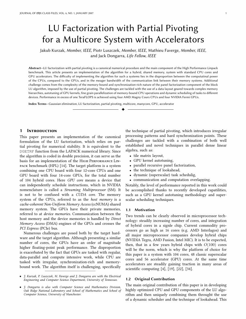
where L is a unit lower triangular matrix, U is an uppertriangular matrix and P is a permutation matrix. The blockLU factorization algorithm [12] proceeds in the followingsteps: Initially, a set of NB columns (the panel) is factoredand a pivoting pattern is produced. Then the elementarytransformations, resulting from the panel factorization, areapplied in block fashion to the remaining part of the ma-trix (the trailing submatrix). First, NB rows of the trailingsubmatrix are swapped, according to the pivoting pattern.Then a triangular solve is applied to the top NB rows of thetrailing submatrix. Finally, matrix multiplication of the formAij ← Aij−Aik×Akj is performed, where Aik is the panelwithout the top NB rows, Akj is the top NB rows of thetrailing submatrix and Aij is the trailing submatrix withoutthe top NB rows. Then the procedure is applied repeatedly,descending down the diagonal of the matrix (Figure 1). Theblock algorithm is described in detail in section 2.6.3. of thebook by Demmel [12]
U (done)
L (d
on
e)
Aij
Akj
Aik
Fig. 1. Block LU factorization (Level 3 BLAS algorithm ofLAPACK) [12].
In the LAPACK software library, panel factorization isperformed by the DGETF2 routine, swapping of rows by the
DLASWP routine, triangular solve by the DTRSM routine andmatrix multiplication by the DGEMM routine. The DGETF2and DLASWP routines are implemented in LAPACK, whilethe DTRSM and DGEMM routines are part of the Basic LinearAlgebra Subroutines (BLAS) standard. LAPACK is an academicproject and therefore the source code is freely distributedonline. BLAS is a set of standardized routines, and is availablein commercial packages (e.g. MKL from Intel, ACML fromAMD, ESSL from IBM), in academic packages (e.g. ATLAS)and also as a reference implementation in FORTRAN 77from the Netlib software repository. Notably, the last sourceprovides an unoptimized code, which is only meant to serveas the deVnition of BLAS.
2.2 Superscalar SchedulingSuperscalar schedulers exploit multithreaded parallelism ina similar way as sperscalar processors exploit InstructionLevel Parallelism (ILP). Scheduling proceeds under the con-straints of data hazards: Read after Write (RaW), Write afterRead (RaW) and Write after Write (RaW). In addition, theWaR and WaW dependencies can be removed by usingthe tachnique of renaming. The Vrst processor archtectureto use superscalar scheduling was the CDC 6600, and theVrst architecture to use register renaming was the IBMSystem/360 (Tomasulo algorithm).
In the context of multithreading, superscalar schedulingis a way of automatically parallelizing serial code. Theprogrammer is responsible for encapsulating the work inside-eUect-free functions (parallel tasks) and providing di-rectionality of their parameters (input, output, inout), andthe scheduling is left to the runtime. Scheduling is done byconceptually exploring the Directed Acyclic Graph (DAG), ortask graph, of the problem. In practice the DAG is explored ina sliding window fashion and actually not explicitly built. It isrepresented inplicitly through data structures such as linkedlists and hash tables, keeping track of data dependencies.
The oldest system, that the authors are aware of, is theJade project from Stanford Univesity [37], [38]. Two well es-tablished projects are StarSs from Barcelona SupercomputerCenter [35], [36] and StarPU from INRIA Bordeaux [3]. Thescheduler used in this work is QUeuing And Runtime forKernels (QUARK) [46], currently the system of choice forthe PLASMA project [20]. It is suitable for this work dueto a number of vital extensions, discussed in more detail insection 3.6.
2.3 NVIDIA CUDAIn November 2006, NVIDIA introduced the Compute UniVedDevice Architecture (CUDATM), a general purpose parallelcomputing architecture, with a new parallel programmingmodel and instruction set architecture, that leverages theparallel compute engine in NVIDIA GPUs to solve complexcomputational problems [33].
At its core are three key abstractions: a hierarchy of threadgroups, shared memories, and barrier synchronization, thatare exposed to the programmer as a set of language exten-sions. They guide the programmer to partition the problem
JOURNAL OF LATEX CLASS FILES, VOL. 6, NO. 1, JANUARY 2007 3
into coarse sub-problems that can be solved independentlyin parallel by blocks of threads, and each sub-problem intoVner pieces that can be solved cooperatively in parallel byall threads within the block. CUDA C extends C by allowingthe programmer to deVne C functions, called kernels, that,when called, are executed N times in parallel by N diUerentCUDA threads.
The CUDA architecture is built around a scalable arrayof multithreaded Streaming Multiprocessors (SMs). When aCUDA program on the host CPU invokes a kernel grid, theblocks of the grid are enumerated and distributed to multi-processors with available execution capacity. The threads ofa thread block execute concurrently on one multiprocessor,and multiple thread blocks can execute concurrently on onemultiprocessor. As thread blocks terminate, new blocks arelaunched on the vacated multiprocessors.
A multiprocessor is designed to execute hundreds ofthreads concurrently. To manage such a large amount ofthreads, it employs a unique architecture called Single-Instruction, Multiple-Thread (SIMT). The instructions arepipelined to leverage instruction-level parallelism within asingle thread, as well as thread-level parallelism extensivelywith simultaneous hardware multithreading. However, unlikeCPU cores, they are issued in order and there is no branchprediction and no speculative execution.
The multiprocessor creates, manages, schedules, and exe-cutes threads in groups of 32 parallel threads called warps.Individual threads composing a warp start together at thesame program address, but they have their own instructionaddress counter and register state and are therefore free tobranch and execute independently. The term warp originatesfrom weaving, the Vrst parallel thread technology. When amultiprocessor is given one or more thread blocks to execute,it partitions them into warps that get scheduled by a warpscheduler for execution.
2.4 Related Work
Work on GPU accelerated dense linear algebra routinesstarted before general purpose programming environments,such as CUDA or OpenCL, were available. This time isoftern referred to, somewhat ironically, as the General PurposeGPU (GPGPU) era. The earliest implementation of a matrixfactorization was reported by Galoppo [15], who imple-mented the non-blocked LU decomposition without pivoting,with partial pivoting and with full pivoting.
More papers followed when CUDA became available,largly thanks to the CUBLAS library (CUDA BLAS) providedby NVIDIA. Implementations of dense matrix factorizationswere reported by Barrachina et al. [6], Baboulin et al. [5],and Castillo et al. [9]. Seminal work was done by Volkov andDemmel [45], where notably a two-GPU implementation ofthe LU factorization was reported, and 1D block cyclic datadistribution was used. It was followed by the work of Tomovet al. [42], [43] in the context of the Matrix Algebra for GPUsand Multicore Architectures (MAGMA) library.Important part of these developments is the work solely
focusing on optimizing matrix multiplication. Early work on
tuning GEMMs in CUDA for NVIDIA GPUs targeted the pre-vious generation of GPUs, of the GT200 architecture, such asthe popular GTX 280. Pioneering work was done by Volkovand Demmel [45]. Similar eUorts followed in the MAGMAproject [29]. The introduction of the NVIDIA Fermi architec-ture triggered the development of MAGMA GEMM kernelsfor that architecture [31], [32], which recently evolved intoa systematic autotuning approach named Automatic StencilTunerR for Accelerators (ASTRA) [28]. Other related eUortsinclude the compiler-based work by Rudy et al. [39] and Cuiet al. [11], and low-level kernel development by Nakasato [30]and Tan et al. [41].
Dense linear albebra codes, including the Cholesky, LU andQR factorizations have also been oYoaded to the IBM CellB. E. accelerator [10], [23]–[25]. Two eUorts are speciVcallyworth mentioning. Chen et al. developed a single precisionimplementation of the Linpack benchmark for the QS20system, which relied on a tile matrix layout and a cache-resident panel factorization [10]. Kistler et al. developed adouble precision implementation of the Linpack benchmarkfor the QS22 system, which employed a recursive panelfactorization [21].
Panel factorization has been successfully parallelized andincorporated into a general LU factorization code [7] usingan optimized implementation of mostly Level 1 BLAS. Thiswas done in a Wat parallelism model with Block SynchronousProcessing (BSP) model [44] also referred to as fork-joinexecution. The authors refer to their approach as ParallelCache Assignment (PCA). Our work on parallelizing thepanel factorization [13] diUers in a few key aspects. Weemploy recursive formulation of the factorization [16] andtherefore are able to use Level 3 BLAS as opposed to justLevel 1 BLAS. Another important diUerence is the nestedparallelism with which we have the Wexibility to allocateonly a small set of cores for the panel work while othercores carry on with the remaining tasks such as the Schurcomplement updates. Finally, we use dynamic schedulingthat executes Vne grained tasks asynchronously, which isdrastically diUerent from a BSP or fork-join parallelism.
3 SolutionThe solution follows the design principles of the PLASMAnumerical library by storing and processing the matrix bytiles and using dynamic, dependency-driven, runtime taskscheduling. The approach was successfully applied to the QRfactorization in the past [27]. Here similar methodology is ap-plied to the LU factorization for a system with multiple GPUs.The sections to follow outline the main hybridization idea,provide the motivation for the use of a tile matrix layout,describe the development of CPU and GPU kernels, explainthe scheduling methodology and discuss the communicationrequirements.
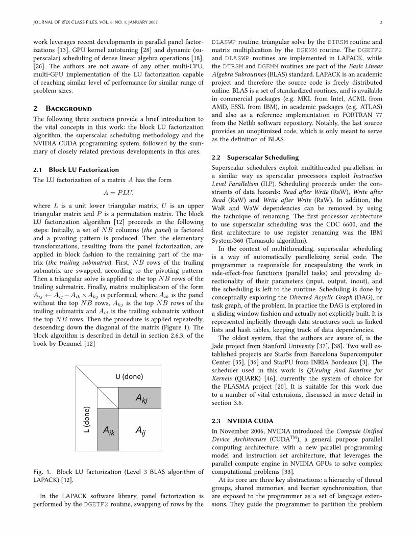
3.1 HybridizationThe main hybridization idea is captured on Figure 2 and relieson representing the work as a Directed Acyclic Graph (DAG)and dynamic task scheduling, with CPU cores handling the
JOURNAL OF LATEX CLASS FILES, VOL. 6, NO. 1, JANUARY 2007 4
complex Vne-grained tasks on the critical path and GPUshandling the coarse-grained data-parallel tasks outside of thecritical path.
Fig. 2. The basic hybridization idea, with Vne-grained taskson the critical path being dispatched to individual CPU coresand coarse-grained tasks outside of the critical path beingdispatched to GPU devices.
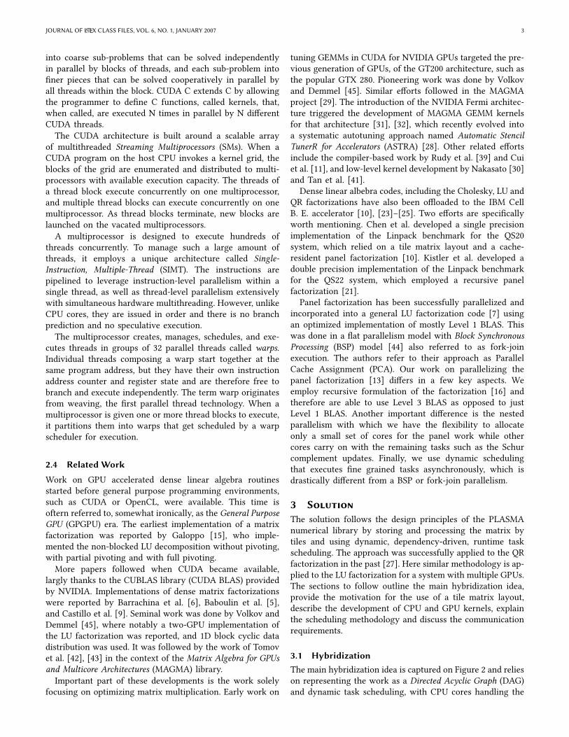
Some number of columns (lookahead) are assigned to theCPUs and the rest of the matrix is assigned to the GPUsin a 1D block-cyclic fashion (Figure 3). In each step ofthe factorization, the CPUs factor a panel and update theirportion of the trailing submatrix, while the GPUs updatetheir portions of the trailing submatrix. After each step, onecolumn of tiles shifts from the GPUs to the CPUs. (fromdevice memory to host memory).
CPU cores GPU 0 GPU 1
step 3
step 2step 1
step 0 step 0 step 0
GPU 1
step 1 step 1
GPU 0
step 2
GPU 0
step 2
GPU 1
Fig. 3. The splitting of work between the CPUs and theGPUs, with a number of columns on the left side (lookahead)processed by the CPUs and the remaining columns on theright side processed by the GPUs.
The main advantage of this solution is the capability ofoverlapping the CPU processing and the GPU processing(and also overlapping of communication and computation).
The GPUs have to be idle while the Vrst panel is factored.However, the factorization of the second panel can proceedin prallel with the application of the Vrst panel to the trailingsubmatrix. In practice, the level of overlapping is muchbigger, i.e., the panel factorizations are a few steps aheadof updates.
3.2 Data Layout
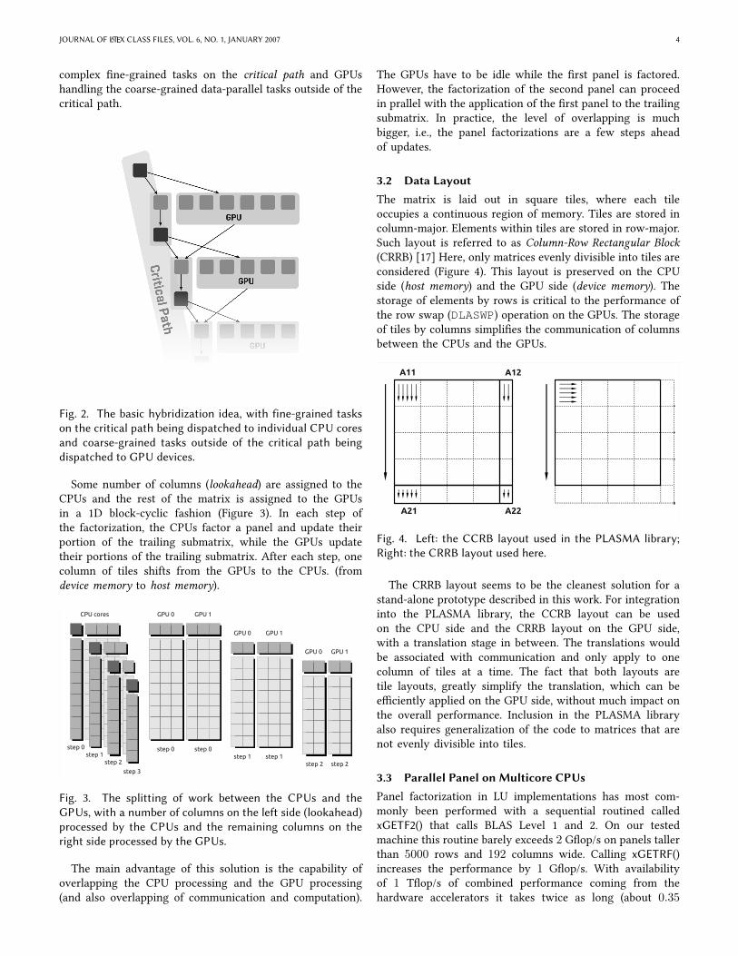
The matrix is laid out in square tiles, where each tileoccupies a continuous region of memory. Tiles are stored incolumn-major. Elements within tiles are stored in row-major.Such layout is referred to as Column-Row Rectangular Block(CRRB) [17] Here, only matrices evenly divisible into tiles areconsidered (Figure 4). This layout is preserved on the CPUside (host memory) and the GPU side (device memory). Thestorage of elements by rows is critical to the performance ofthe row swap (DLASWP) operation on the GPUs. The storageof tiles by columns simpliVes the communication of columnsbetween the CPUs and the GPUs.
A11
A21
A12
A22
Fig. 4. Left: the CCRB layout used in the PLASMA library;Right: the CRRB layout used here.
The CRRB layout seems to be the cleanest solution for astand-alone prototype described in this work. For integrationinto the PLASMA library, the CCRB layout can be usedon the CPU side and the CRRB layout on the GPU side,with a translation stage in between. The translations wouldbe associated with communication and only apply to onecolumn of tiles at a time. The fact that both layouts aretile layouts, greatly simplify the translation, which can beeXciently applied on the GPU side, without much impact onthe overall performance. Inclusion in the PLASMA libraryalso requires generalization of the code to matrices that arenot evenly divisible into tiles.
3.3 Parallel Panel on Multicore CPUs
Panel factorization in LU implementations has most com-monly been performed with a sequential routined calledxGETF2() that calls BLAS Level 1 and 2. On our testedmachine this routine barely exceeds 2 GWop/s on panels tallerthan 5000 rows and 192 columns wide. Calling xGETRF()increases the performance by 1 GWop/s. With availabilityof 1 TWop/s of combined performance coming from thehardware accelerators it takes twice as long (about 0.35
JOURNAL OF LATEX CLASS FILES, VOL. 6, NO. 1, JANUARY 2007 5
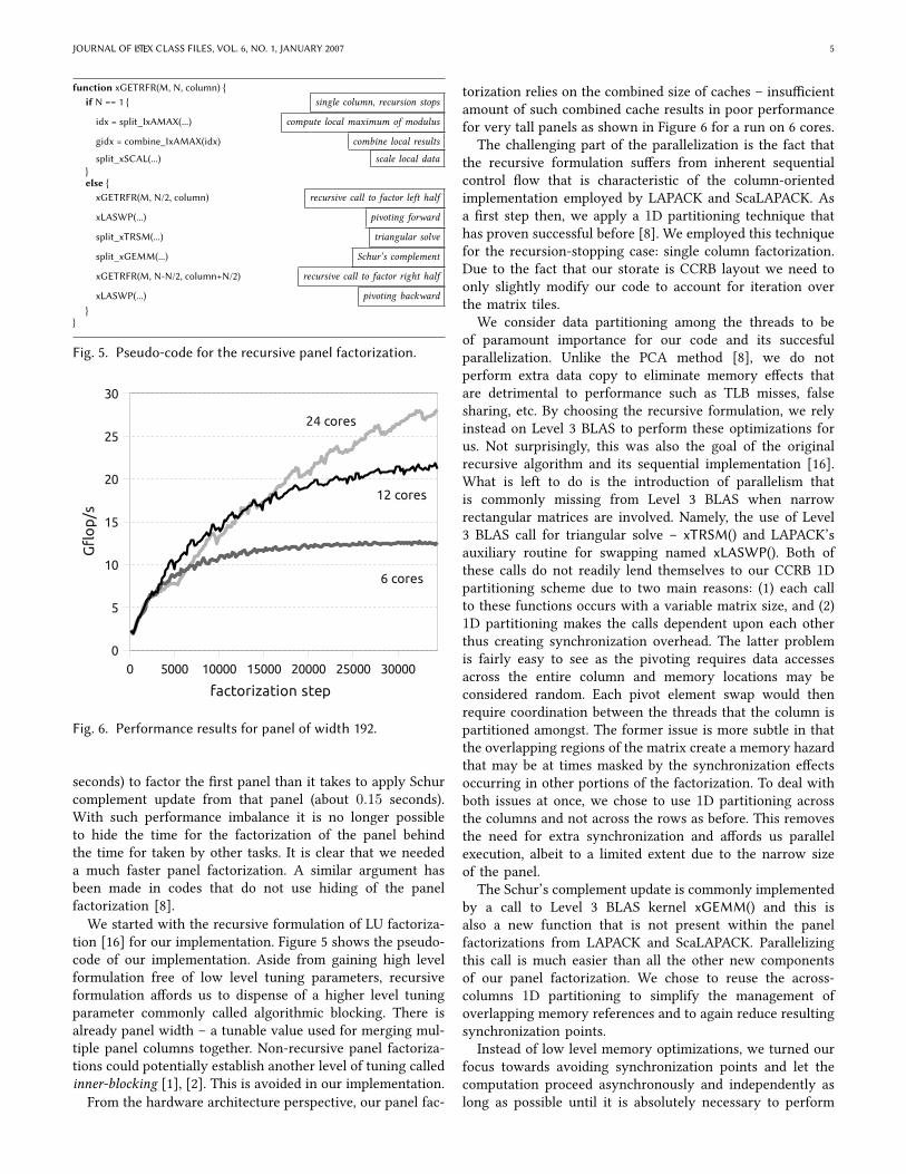
function xGETRFR(M, N, column) {if N == 1 { single column, recursion stops
idx = split_IxAMAX(...) compute local maximum of modulus
gidx = combine_IxAMAX(idx) combine local results
split_xSCAL(...) scale local data}else {
xGETRFR(M, N/2, column) recursive call to factor left half
xLASWP(...) pivoting forward
split_xTRSM(...) triangular solve
split_xGEMM(...) Schur’s complement
xGETRFR(M, N-N/2, column+N/2) recursive call to factor right half
xLASWP(...) pivoting backward}
}
Fig. 5. Pseudo-code for the recursive panel factorization.
0 5000 10000 15000 20000 25000 300000
5
10
15
20
25
30
factorization step
Gfl
op
/s
6 cores
12 cores
24 cores
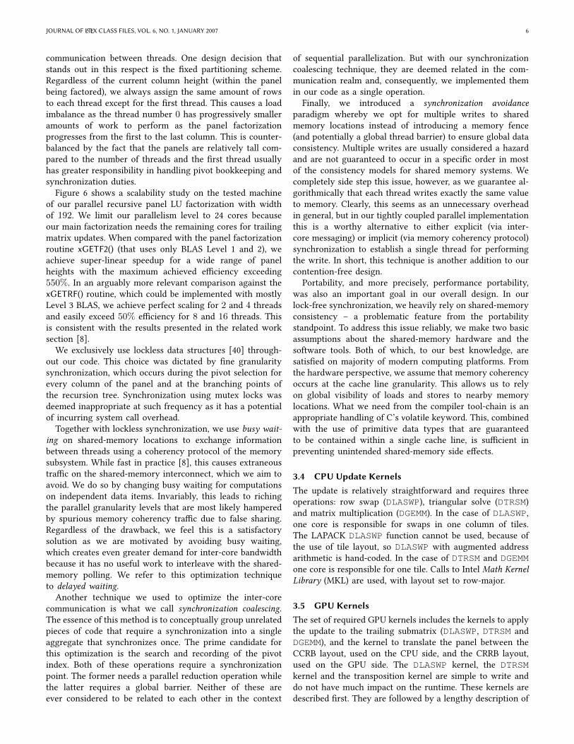
Fig. 6. Performance results for panel of width 192.
seconds) to factor the Vrst panel than it takes to apply Schurcomplement update from that panel (about 0.15 seconds).With such performance imbalance it is no longer possibleto hide the time for the factorization of the panel behindthe time for taken by other tasks. It is clear that we neededa much faster panel factorization. A similar argument hasbeen made in codes that do not use hiding of the panelfactorization [8].
We started with the recursive formulation of LU factoriza-tion [16] for our implementation. Figure 5 shows the pseudo-code of our implementation. Aside from gaining high levelformulation free of low level tuning parameters, recursiveformulation aUords us to dispense of a higher level tuningparameter commonly called algorithmic blocking. There isalready panel width – a tunable value used for merging mul-tiple panel columns together. Non-recursive panel factoriza-tions could potentially establish another level of tuning calledinner-blocking [1], [2]. This is avoided in our implementation.From the hardware architecture perspective, our panel fac-
torization relies on the combined size of caches – insuXcientamount of such combined cache results in poor performancefor very tall panels as shown in Figure 6 for a run on 6 cores.
The challenging part of the parallelization is the fact thatthe recursive formulation suUers from inherent sequentialcontrol Wow that is characteristic of the column-orientedimplementation employed by LAPACK and ScaLAPACK. Asa Vrst step then, we apply a 1D partitioning technique thathas proven successful before [8]. We employed this techniquefor the recursion-stopping case: single column factorization.Due to the fact that our storate is CCRB layout we need toonly slightly modify our code to account for iteration overthe matrix tiles.
We consider data partitioning among the threads to beof paramount importance for our code and its succesfulparallelization. Unlike the PCA method [8], we do notperform extra data copy to eliminate memory eUects thatare detrimental to performance such as TLB misses, falsesharing, etc. By choosing the recursive formulation, we relyinstead on Level 3 BLAS to perform these optimizations forus. Not surprisingly, this was also the goal of the originalrecursive algorithm and its sequential implementation [16].What is left to do is the introduction of parallelism thatis commonly missing from Level 3 BLAS when narrowrectangular matrices are involved. Namely, the use of Level3 BLAS call for triangular solve – xTRSM() and LAPACK’sauxiliary routine for swapping named xLASWP(). Both ofthese calls do not readily lend themselves to our CCRB 1Dpartitioning scheme due to two main reasons: (1) each callto these functions occurs with a variable matrix size, and (2)1D partitioning makes the calls dependent upon each otherthus creating synchronization overhead. The latter problemis fairly easy to see as the pivoting requires data accessesacross the entire column and memory locations may beconsidered random. Each pivot element swap would thenrequire coordination between the threads that the column ispartitioned amongst. The former issue is more subtle in thatthe overlapping regions of the matrix create a memory hazardthat may be at times masked by the synchronization eUectsoccurring in other portions of the factorization. To deal withboth issues at once, we chose to use 1D partitioning acrossthe columns and not across the rows as before. This removesthe need for extra synchronization and aUords us parallelexecution, albeit to a limited extent due to the narrow sizeof the panel.
The Schur’s complement update is commonly implementedby a call to Level 3 BLAS kernel xGEMM() and this isalso a new function that is not present within the panelfactorizations from LAPACK and ScaLAPACK. Parallelizingthis call is much easier than all the other new componentsof our panel factorization. We chose to reuse the across-columns 1D partitioning to simplify the management ofoverlapping memory references and to again reduce resultingsynchronization points.
Instead of low level memory optimizations, we turned ourfocus towards avoiding synchronization points and let thecomputation proceed asynchronously and independently aslong as possible until it is absolutely necessary to perform
JOURNAL OF LATEX CLASS FILES, VOL. 6, NO. 1, JANUARY 2007 6
communication between threads. One design decision thatstands out in this respect is the Vxed partitioning scheme.Regardless of the current column height (within the panelbeing factored), we always assign the same amount of rowsto each thread except for the Vrst thread. This causes a loadimbalance as the thread number 0 has progressively smalleramounts of work to perform as the panel factorizationprogresses from the Vrst to the last column. This is counter-balanced by the fact that the panels are relatively tall com-pared to the number of threads and the Vrst thread usuallyhas greater responsibility in handling pivot bookkeeping andsynchronization duties.
Figure 6 shows a scalability study on the tested machineof our parallel recursive panel LU factorization with widthof 192. We limit our parallelism level to 24 cores becauseour main factorization needs the remaining cores for trailingmatrix updates. When compared with the panel factorizationroutine xGETF2() (that uses only BLAS Level 1 and 2), weachieve super-linear speedup for a wide range of panelheights with the maximum achieved eXciency exceeding550%. In an arguably more relevant comparison against thexGETRF() routine, which could be implemented with mostlyLevel 3 BLAS, we achieve perfect scaling for 2 and 4 threadsand easily exceed 50% eXciency for 8 and 16 threads. Thisis consistent with the results presented in the related worksection [8].
We exclusively use lockless data structures [40] through-out our code. This choice was dictated by Vne granularitysynchronization, which occurs during the pivot selection forevery column of the panel and at the branching points ofthe recursion tree. Synchronization using mutex locks wasdeemed inappropriate at such frequency as it has a potentialof incurring system call overhead.
Together with lockless synchronization, we use busy wait-ing on shared-memory locations to exchange informationbetween threads using a coherency protocol of the memorysubsystem. While fast in practice [8], this causes extraneoustraXc on the shared-memory interconnect, which we aim toavoid. We do so by changing busy waiting for computationson independent data items. Invariably, this leads to richingthe parallel granularity levels that are most likely hamperedby spurious memory coherency traXc due to false sharing.Regardless of the drawback, we feel this is a satisfactorysolution as we are motivated by avoiding busy waiting,which creates even greater demand for inter-core bandwidthbecause it has no useful work to interleave with the shared-memory polling. We refer to this optimization techniqueto delayed waiting.
Another technique we used to optimize the inter-corecommunication is what we call synchronization coalescing.The essence of this method is to conceptually group unrelatedpieces of code that require a synchronization into a singleaggregate that synchronizes once. The prime candidate forthis optimization is the search and recording of the pivotindex. Both of these operations require a synchronizationpoint. The former needs a parallel reduction operation whilethe latter requires a global barrier. Neither of these areever considered to be related to each other in the context
of sequential parallelization. But with our synchronizationcoalescing technique, they are deemed related in the com-munication realm and, consequently, we implemented themin our code as a single operation.
Finally, we introduced a synchronization avoidanceparadigm whereby we opt for multiple writes to sharedmemory locations instead of introducing a memory fence(and potentially a global thread barrier) to ensure global dataconsistency. Multiple writes are usually considered a hazardand are not guaranteed to occur in a speciVc order in mostof the consistency models for shared memory systems. Wecompletely side step this issue, however, as we guarantee al-gorithmically that each thread writes exactly the same valueto memory. Clearly, this seems as an unnecessary overheadin general, but in our tightly coupled parallel implementationthis is a worthy alternative to either explicit (via inter-core messaging) or implicit (via memory coherency protocol)synchronization to establish a single thread for performingthe write. In short, this technique is another addition to ourcontention-free design.
Portability, and more precisely, performance portability,was also an important goal in our overall design. In ourlock-free synchronization, we heavily rely on shared-memoryconsistency – a problematic feature from the portabilitystandpoint. To address this issue reliably, we make two basicassumptions about the shared-memory hardware and thesoftware tools. Both of which, to our best knowledge, aresatisVed on majority of modern computing platforms. Fromthe hardware perspective, we assume that memory coherencyoccurs at the cache line granularity. This allows us to relyon global visibility of loads and stores to nearby memorylocations. What we need from the compiler tool-chain is anappropriate handling of C’s volatile keyword. This, combinedwith the use of primitive data types that are guaranteedto be contained within a single cache line, is suXcient inpreventing unintended shared-memory side eUects.
3.4 CPU Update KernelsThe update is relatively straightforward and requires threeoperations: row swap (DLASWP), triangular solve (DTRSM)and matrix multiplication (DGEMM). In the case of DLASWP,one core is responsible for swaps in one column of tiles.The LAPACK DLASWP function cannot be used, because ofthe use of tile layout, so DLASWP with augmented addressarithmetic is hand-coded. In the case of DTRSM and DGEMMone core is responsible for one tile. Calls to Intel Math KernelLibrary (MKL) are used, with layout set to row-major.
3.5 GPU KernelsThe set of required GPU kernels includes the kernels to applythe update to the trailing submatrix (DLASWP, DTRSM andDGEMM), and the kernel to translate the panel between theCCRB layout, used on the CPU side, and the CRRB layout,used on the GPU side. The DLASWP kernel, the DTRSMkernel and the transposition kernel are simple to write anddo not have much impact on the runtime. These kernels aredescribed Vrst. They are followed by a lengthy description of
JOURNAL OF LATEX CLASS FILES, VOL. 6, NO. 1, JANUARY 2007 7
the DGEMM kernel, which dominates the execution time andis complex to optimize to the fullest.
3.5.1 DLASWP
The DLASWP routine swaps rows of the trailing submatrixaccording to the pivoting pattern, established in the panelfactorization. This operation only performs data motion andthe GPUs are very sensitive to the matrix layout in memory.In raw-major layout, threads in a warp can simultaneouslyaccess consecutive memory locations. This is not the case incolumn-major layout, where threads access memory with astride. In this case, each thread generates a separate memoryrequest, which is devastating to performance. As a result,performance is two orders of magnitude lower than in theformer case, and the swap operation dominates the update.
This forces the use of the CRRB format, i.e., row-majorstorage of elements within tiles. As soon as the CRRB formatis used a straightforward implementation of the DLASWPoperation completely suXces. Each thread block is taskedwith swaps in one column of tiles and creates NB threadsto perform them, one thread per one column of elements.Although this may not be the fastest possible way of im-plementing the swap, when implemented like that, the swapoperation becomes negligible.
3.5.2 DTRSM
The DTRSM routine uses the lower triangle of the NB ×NBdiagonal block to apply triangular solve to the block ofright-hand-sides formed by the top NB rows of the trailingsubmatrix. An eXcient implementation of this routine on aGPU is diXcult due to the data-parallel nature of GPUs andsmall size of the solve (32 ≤ NB ≤ 288).
In such case, the standard procedure for GPUs is to replacethe in-place triangular solve operation with an out-of-placemultiplication of the block of right-hand-sides by the inverseof the triangle. After the panel factorization, one CPU coreapplies the triangular solve to an NB×NB identity matrix.In the update phase, the GPUs call the DGEMM routine toapply the inverted matrix to the block of right-hand-sides inan out-of-place fashion, followed by a copy of the result tothe location of the original block of right-hand-sides.
This operation executes at the speed of the DGEMM op-eration, with twice as many FLOPs as the standard DTRSMroutine. This is the fastest way of implementing it, knownto the authors. Because it only aUects small portion of thetrailing submatrix, its execution time is negligible, comparedto the large DGEMM, which follows.
3.5.3 CCRB - CRRB Conversion
As already mentioned in section 3.2, tile layout has numerousadvantages and is the layout of choice for the PLASMAlibrary. However, PLASMA lays out data in tiles by columns,and the GPUs require data to be laid out out by rows.Otherwise the DLASWP operation cannot perform adequately.Therefore, an operation is needed which internally transposeseach tile, i.e., makes a conversion between the CCRB and theCRRB formats.
A very simple implementation is used here. Each threadblock launches 1024 threads arranged in a 32 × 32 grid,and each thread swaps two elements of the matrix to theirtransposed locations. The submatrix (column) being trans-posed is overlaid with a rectangular grid of blocks. Threadswith the Vrst element below the tile’s diagonal perform theswap. Threads with the Vrst element above the diagonal quit.As naive as this implementation is, its execution time isnegligible.
3.5.4 DGEMMThe most important operation oYoaded to the GPUs is theSchur complement part of the LU factorization, which is amatrix multiplication of the form C = C −A×B, where Ais N ×K , B is K ×N and C is M ×N and in most casesM = N � K . The value of K corresponds to the width ofthe panel in each step of the factorization and is commonlyreferred to as NB in LAPACK and PLASMA nomenclature.
The development of DGEMM presented here follows tosome extent the autotuning methodology used for producingGEMM kernels for the MAGMA project [28]. There are,however, major diUerences: First, the code has been rewrittento operate on data in row-major layout. Second, addressarithmetic has been changed to work on matrices storedin tiles. Generation and pruning of the search space hasalso been modiVed to account for tiling of input matrices,and Vnally, benchmarking has been done for the case of(M = N � K = NB), instead of the usual case of(M ' N ' K).
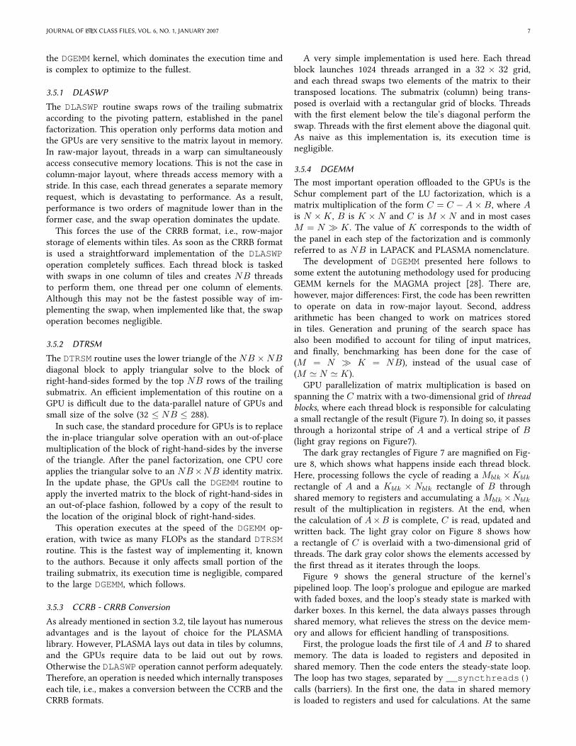
GPU parallelization of matrix multiplication is based onspanning the C matrix with a two-dimensional grid of threadblocks, where each thread block is responsible for calculatinga small rectangle of the result (Figure 7). In doing so, it passesthrough a horizontal stripe of A and a vertical stripe of B(light gray regions on Figure7).
The dark gray rectangles of Figure 7 are magniVed on Fig-ure 8, which shows what happens inside each thread block.Here, processing follows the cycle of reading a Mblk ×Kblk
rectangle of A and a Kblk × Nblk rectangle of B throughshared memory to registers and accumulating a Mblk×Nblk
result of the multiplication in registers. At the end, whenthe calculation of A×B is complete, C is read, updated andwritten back. The light gray color on Figure 8 shows howa rectangle of C is overlaid with a two-dimensional grid ofthreads. The dark gray color shows the elements accessed bythe Vrst thread as it iterates through the loops.
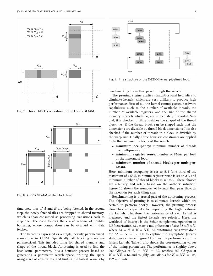
Figure 9 shows the general structure of the kernel’spipelined loop. The loop’s prologue and epilogue are markedwith faded boxes, and the loop’s steady state is marked withdarker boxes. In this kernel, the data always passes throughshared memory, what relieves the stress on the device mem-ory and allows for eXcient handling of transpositions.
First, the prologue loads the Vrst tile of A and B to sharedmemory. The data is loaded to registers and deposited inshared memory. Then the code enters the steady-state loop.The loop has two stages, separated by __syncthreads()calls (barriers). In the Vrst one, the data in shared memoryis loaded to registers and used for calculations. At the same
JOURNAL OF LATEX CLASS FILES, VOL. 6, NO. 1, JANUARY 2007 8
Nblk
Mblk
Kblk
Kblk
NB
NB
NB % Mblk = 0NB % Nblk = 0NB % Kblk = 0
A C
B
Fig. 7. Thread block’s operation for the CRRB GEMM.
Nblk
Mblk
Kblk
Kblk blockDim.y
bloc
kDim
.x
A
B
C
Fig. 8. CRRB GEMM at the block level.
time, new tiles of A and B are being fetched. In the secondstep, the newly fetched tiles are dropped to shared memory,which is than consumed as processing transitions back tostep one. The code follows the classic scheme of double-buUering, where computation can be overlaid with datafetches.
The kernel is expressed as a single, heavily parametrized,source Vle in CUDA. SpeciVcally, all blocking sizes areparametrized. This includes tiling for shared memory andshape of the thread block. Autotuning is used to Vnd thebest kernel parameters. It is a heuristic process based ongenerating a parameter search space, pruning the spaceusing a set of constraints, and Vnding the fastest kernels by
SHM
REG
CMP
MEM
REG SHM
REG SHM
REG
CMP
MEM
REG
SHM
even
odd
Fig. 9. The structure of the DGEMM kernel pipelined loop.
benchmarking those that pass through the selection.The pruning engine applies straightforward heuristics to
eliminate kernels, which are very unlikely to produce highperformance. First of all, the kernel cannot exceed hardwarecapabilities, such as the number of available threads, thenumber of available registers, and the size of the sharedmemory. Kernels which do, are immediately discarded. Sec-ond, it is checked if tiling matches the shaped of the threadblock, i.e., if the thread block can be shaped such that tiledimensions are divisible by thread block dimensions. It is alsochecked if the number of threads in a block is divisible bythe warp size. Finally, three heuristic constraints are appliedto further narrow the focus of the search:
• minimum occupancy: minimum number of threadsper multiprocessor,
• minimum register reuse: number of FMAs per loadin the innermost loop,
• minimum number of thread blocks per multipro-cessor.
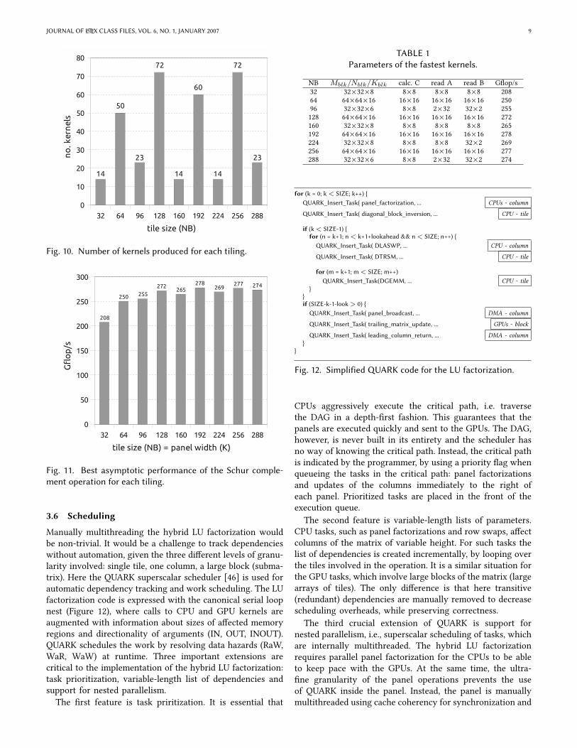
Here, minimum occupancy is set to 512 (one third of themaximum of 1,536), minimum register reuse is set to 2.0, andminimum number of thread blocks is set to 2. These choicesare arbitrary and solely based on the authors’ intuition.Figure 10 shows the numbers of kernels that pass throughthe selection for each tiling size.
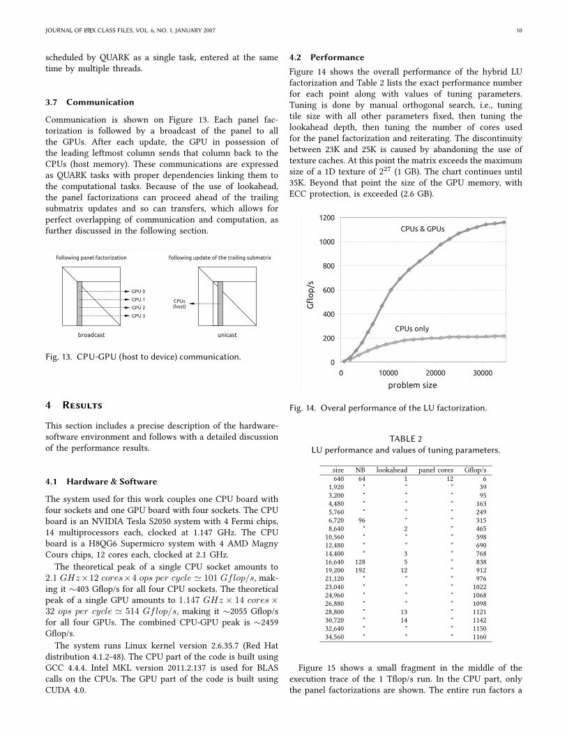
Benchmarking is a crucial part of the autotuning process.The objective of pruning is to eliminate kernels which arecertain to perform poorly. However, the pruning processalone has no capability to pinpointing the high perform-ing kernels. Therefore, the performance of each kernel ismeasured and the fastest kernels are selected. Here, theworkload of interest is the Schur complement operation inLU factorization, i.e., matrix multiplication of sizeM×N×K ,where M = N � K = NB. All autotuning runs were donefor M = N = 12, 000 to capture the asymptotic (steadystate) performance. Figure 11 shows the performance of thefastest kernels. Table 1 also shows the corresponding valuesof the tuning parameters. The performance is slighlty above200 GWop/s at K = NB = 32, reaches 250 GWop/s atK = NB = 64 and roughly 280 GWop/s for K = NB = 128,192 and 256.
JOURNAL OF LATEX CLASS FILES, VOL. 6, NO. 1, JANUARY 2007 9
32 64 96 128 160 192 224 256 2880
10
20
30
40
50
60
70
80
tile size (NB)
no
. ker
nel
s
14
50
23
72
60
72
23
14 14
Fig. 10. Number of kernels produced for each tiling.
32 64 96 128 160 192 224 256 2880
50
100
150
200
250
300
tile size (NB) = panel width (K)
Gfl
op
/s
208
250 255
272265
278269
277 274
Fig. 11. Best asymptotic performance of the Schur comple-ment operation for each tiling.
3.6 Scheduling
Manually multithreading the hybrid LU factorization wouldbe non-trivial. It would be a challenge to track dependencieswithout automation, given the three diUerent levels of granu-larity involved: single tile, one column, a large block (subma-trix). Here the QUARK superscalar scheduler [46] is used forautomatic dependency tracking and work scheduling. The LUfactorization code is expressed with the canonical serial loopnest (Figure 12), where calls to CPU and GPU kernels areaugmented with information about sizes of aUected memoryregions and directionality of arguments (IN, OUT, INOUT).QUARK schedules the work by resolving data hazards (RaW,WaR, WaW) at runtime. Three important extensions arecritical to the implementation of the hybrid LU factorization:task prioritization, variable-length list of dependencies andsupport for nested parallelism.
The Vrst feature is task priritization. It is essential that
TABLE 1Parameters of the fastest kernels.
NB Mblk/Nblk/Kblk calc. C read A read B GWop/s32 32×32×8 8×8 8×8 8×8 20864 64×64×16 16×16 16×16 16×16 25096 32×32×6 8×8 2×32 32×2 255128 64×64×16 16×16 16×16 16×16 272160 32×32×8 8×8 8×8 8×8 265192 64×64×16 16×16 16×16 16×16 278224 32×32×8 8×8 8×8 32×2 269256 64×64×16 16×16 16×16 16×16 277288 32×32×6 8×8 2×32 32×2 274
for (k = 0; k < SIZE; k++) {QUARK_Insert_Task( panel_factorization, ... CPUs - column
QUARK_Insert_Task( diagonal_block_inversion, ... CPU - tile
if (k< SIZE-1) {for (n = k+1; n < k+1+lookahead && n < SIZE; n++) {QUARK_Insert_Task( DLASWP, ... CPU - column
QUARK_Insert_Task( DTRSM, ... CPU - tile
for (m = k+1; m < SIZE; m++)QUARK_Insert_Task(DGEMM, ... CPU - tile
}}if (SIZE-k-1-look > 0) {
QUARK_Insert_Task( panel_broadcast, ... DMA - column
QUARK_Insert_Task( trailing_matrix_update, ... GPUs - block
QUARK_Insert_Task( leading_column_return, ... DMA - column}
}
Fig. 12. SimpliVed QUARK code for the LU factorization.
CPUs aggressively execute the critical path, i.e. traversethe DAG in a depth-Vrst fashion. This guarantees that thepanels are executed quickly and sent to the GPUs. The DAG,however, is never built in its entirety and the scheduler hasno way of knowing the critical path. Instead, the critical pathis indicated by the programmer, by using a priority Wag whenqueueing the tasks in the critical path: panel factorizationsand updates of the columns immediately to the right ofeach panel. Prioritized tasks are placed in the front of theexecution queue.
The second feature is variable-length lists of parameters.CPU tasks, such as panel factorizations and row swaps, aUectcolumns of the matrix of variable height. For such tasks thelist of dependencies is created incrementally, by looping overthe tiles involved in the operation. It is a similar situation forthe GPU tasks, which involve large blocks of the matrix (largearrays of tiles). The only diUerence is that here transitive(redundant) dependencies are manually removed to decreasescheduling overheads, while preserving correctness.
The third crucial extension of QUARK is support fornested parallelism, i.e., superscalar scheduling of tasks, whichare internally multithreaded. The hybrid LU factorizationrequires parallel panel factorization for the CPUs to be ableto keep pace with the GPUs. At the same time, the ultra-Vne granularity of the panel operations prevents the useof QUARK inside the panel. Instead, the panel is manuallymultithreaded using cache coherency for synchronization and
JOURNAL OF LATEX CLASS FILES, VOL. 6, NO. 1, JANUARY 2007 10
scheduled by QUARK as a single task, entered at the sametime by multiple threads.
3.7 Communication
Communication is shown on Figure 13. Each panel fac-torization is followed by a broadcast of the panel to allthe GPUs. After each update, the GPU in possession ofthe leading leftmost column sends that column back to theCPUs (host memory). These communications are expressedas QUARK tasks with proper dependencies linking them tothe computational tasks. Because of the use of lookahead,the panel factorizations can proceed ahead of the trailingsubmatrix updates and so can transfers, which allows forperfect overlapping of communication and computation, asfurther discussed in the following section.
GPU 0
GPU 1
GPU 2
GPU 3
CPUs(host)
broadcast unicast
following panel factorization following update of the trailing submatrix
Fig. 13. CPU-GPU (host to device) communication.
4 Results
This section includes a precise description of the hardware-software environment and follows with a detailed discussionof the performance results.
4.1 Hardware & Software
The system used for this work couples one CPU board withfour sockets and one GPU board with four sockets. The CPUboard is an NVIDIA Tesla S2050 system with 4 Fermi chips,14 multiprocessors each, clocked at 1.147 GHz. The CPUboard is a H8QG6 Supermicro system with 4 AMD MagnyCours chips, 12 cores each, clocked at 2.1 GHz.
The theoretical peak of a single CPU socket amounts to2.1 GHz×12 cores×4 ops per cycle ' 101 Gflop/s, mak-ing it ∼403 GWop/s for all four CPU sockets. The theoreticalpeak of a single GPU amounts to 1.147 GHz × 14 cores×32 ops per cycle ' 514 Gflop/s, making it ∼2055 GWop/sfor all four GPUs. The combined CPU-GPU peak is ∼2459GWop/s.
The system runs Linux kernel version 2.6.35.7 (Red Hatdistribution 4.1.2-48). The CPU part of the code is built usingGCC 4.4.4. Intel MKL version 2011.2.137 is used for BLAScalls on the CPUs. The GPU part of the code is built usingCUDA 4.0.
4.2 Performance
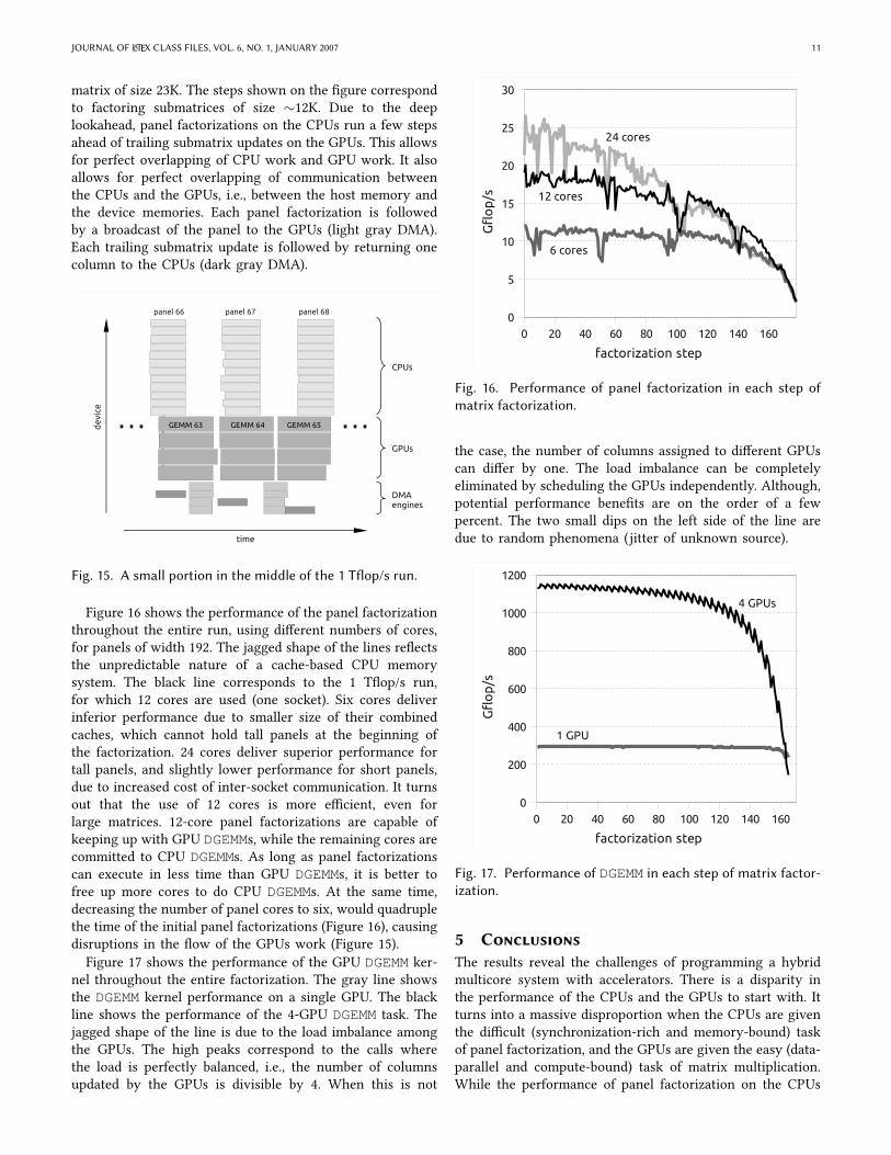
Figure 14 shows the overall performance of the hybrid LUfactorization and Table 2 lists the exact performance numberfor each point along with values of tuning parameters.Tuning is done by manual orthogonal search, i.e., tuningtile size with all other parameters Vxed, then tuning thelookahead depth, then tuning the number of cores usedfor the panel factorization and reiterating. The discontinuitybetween 23K and 25K is caused by abandoning the use oftexture caches. At this point the matrix exceeds the maximumsize of a 1D texture of 227 (1 GB). The chart continues until35K. Beyond that point the size of the GPU memory, withECC protection, is exceeded (2.6 GB).
0 10000 20000 30000
0
200
400
600
800
1000
1200
problem size
Gfl
op
/s
CPUs & GPUs
CPUs only
Fig. 14. Overal performance of the LU factorization.
TABLE 2LU performance and values of tuning parameters.
size NB lookahead panel cores GWop/s640 64 1 12 6
1,920 " " " 393,200 " " " 954,480 " " " 1635,760 " " " 2496,720 96 " " 3158,640 " 2 " 46510,560 " " " 59812,480 " " " 69014,400 " 3 " 76816,640 128 5 " 83819,200 192 12 " 91221,120 " " " 97623,040 " " " 102224,960 " " " 106826,880 " " " 109828,800 " 13 " 112130,720 " 14 " 114232,640 " " " 115034,560 " " " 1160
Figure 15 shows a small fragment in the middle of theexecution trace of the 1 TWop/s run. In the CPU part, onlythe panel factorizations are shown. The entire run factors a
JOURNAL OF LATEX CLASS FILES, VOL. 6, NO. 1, JANUARY 2007 11
matrix of size 23K. The steps shown on the Vgure correspondto factoring submatrices of size ∼12K. Due to the deeplookahead, panel factorizations on the CPUs run a few stepsahead of trailing submatrix updates on the GPUs. This allowsfor perfect overlapping of CPU work and GPU work. It alsoallows for perfect overlapping of communication betweenthe CPUs and the GPUs, i.e., between the host memory andthe device memories. Each panel factorization is followedby a broadcast of the panel to the GPUs (light gray DMA).Each trailing submatrix update is followed by returning onecolumn to the CPUs (dark gray DMA).
panel 66 panel 67 panel 68
GEMM 63 GEMM 64 GEMM 65
CPUs
GPUs
DMAengines
time
de
vice … …
Fig. 15. A small portion in the middle of the 1 TWop/s run.
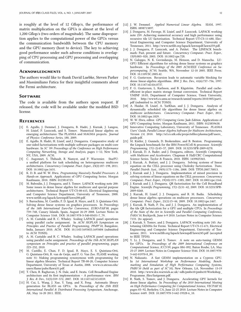
Figure 16 shows the performance of the panel factorizationthroughout the entire run, using diUerent numbers of cores,for panels of width 192. The jagged shape of the lines reWectsthe unpredictable nature of a cache-based CPU memorysystem. The black line corresponds to the 1 TWop/s run,for which 12 cores are used (one socket). Six cores deliverinferior performance due to smaller size of their combinedcaches, which cannot hold tall panels at the beginning ofthe factorization. 24 cores deliver superior performance fortall panels, and slightly lower performance for short panels,due to increased cost of inter-socket communication. It turnsout that the use of 12 cores is more eXcient, even forlarge matrices. 12-core panel factorizations are capable ofkeeping up with GPU DGEMMs, while the remaining cores arecommitted to CPU DGEMMs. As long as panel factorizationscan execute in less time than GPU DGEMMs, it is better tofree up more cores to do CPU DGEMMs. At the same time,decreasing the number of panel cores to six, would quadruplethe time of the initial panel factorizations (Figure 16), causingdisruptions in the Wow of the GPUs work (Figure 15).Figure 17 shows the performance of the GPU DGEMM ker-
nel throughout the entire factorization. The gray line showsthe DGEMM kernel performance on a single GPU. The blackline shows the performance of the 4-GPU DGEMM task. Thejagged shape of the line is due to the load imbalance amongthe GPUs. The high peaks correspond to the calls wherethe load is perfectly balanced, i.e., the number of columnsupdated by the GPUs is divisible by 4. When this is not
0 20 40 60 80 100 120 140 1600
5
10
15
20
25
30
factorization step
Gfl
op
/s
6 cores
12 cores
24 cores
Fig. 16. Performance of panel factorization in each step ofmatrix factorization.
the case, the number of columns assigned to diUerent GPUscan diUer by one. The load imbalance can be completelyeliminated by scheduling the GPUs independently. Although,potential performance beneVts are on the order of a fewpercent. The two small dips on the left side of the line aredue to random phenomena (jitter of unknown source).
0 20 40 60 80 100 120 140 1600
200
400
600
800
1000
1200
factorization step
Gfl
op
/s
1 GPU
4 GPUs
Fig. 17. Performance of DGEMM in each step of matrix factor-ization.
5 ConclusionsThe results reveal the challenges of programming a hybridmulticore system with accelerators. There is a disparity inthe performance of the CPUs and the GPUs to start with. Itturns into a massive disproportion when the CPUs are giventhe diXcult (synchronization-rich and memory-bound) taskof panel factorization, and the GPUs are given the easy (data-parallel and compute-bound) task of matrix multiplication.While the performance of panel factorization on the CPUs
JOURNAL OF LATEX CLASS FILES, VOL. 6, NO. 1, JANUARY 2007 12
is roughly at the level of 12 GWop/s, the performance ofmatrix multiplication on the GPUs is almost at the level of1,200 GWop/s (two orders of magnitude). The same dispropor-tion applies to the computational power of the GPUs versusthe communication bandwidth between the CPU memoryand the GPU memory (host to device). The key to achievinggood performance under such adverse conditions is overlap-ping of CPU processing and GPU processing and overlappingof communication.
AcknowledgmentsThe authors would like to thank David Luebke, Steven Parkerand Massimiliano Fatica for their insightful comments aboutthe Fermi architecture.
SoftwareThe code is available from the authors upon request. Ifreleased, the code will be available under the modiVed BSDlicense.
References[1] E. Agullo, J. Demmel, J. Dongarra, B. Hadri, J. Kurzak, J. Langou,
H. Ltaief, P. Luszczek, and S. Tomov. Numerical linear algebra onemerging architectures: The PLASMA and MAGMA projects. Journalof Physics: Conference Series, 180, 2009.
[2] E. Agullo, B. Hadri, H. Ltaief, and J. Dongarrra. Comparative study ofone-sided factorizations with multiple software packages on multi-corehardware. In SC ’09: Proceedings of the Conference on High PerformanceComputing Networking, Storage and Analysis, pages 1–12, New York,NY, USA, 2009. ACM.
[3] C. Augonnet, S. Thibault, R. Namyst, and P. Wacrenier. StarPU:a uniVed platform for task scheduling on heterogeneous multicorearchitectures. Concurrency Computat. Pract. Exper., 23(2):187–198, 2011.DOI: 10.1002/cpe.1631.
[4] K. D. B. and W. W. Hwu. Programming Massively Parallel Processors: AHands-on Approach. Applications of GPU Computing Series. MorganKaufmann, 2010. ISBN: 0123814723.
[5] M. Baboulin, J. J. Dongarra, and S. Tomov. LAPACK working note 200:Some issues in dense linear algebra for multicore and special purposearchitectures. Technical Report UT-CS-08-615, Electrical Engineeringand Computer Science Department, University of Tennessee, 2008.www.netlib.org/lapack/lawnspdf/lawn200.pdf.
[6] S. Barrachina, M. Castillo, F. D. Igual, R. Mayo, and E. S. Quintana-Orti.Solving dense linear systems on graphics processors. In Proceedingsof the 14th International Euro-Par Converence, EURO-PAR’08, pages739–748, Canary Islands, Spain, August 26-29 2008. Lecture Notes inComputer Science 5168. DOI: 10.1007/978-3-540-85451-7_79.
[7] A. M. Castaldo and R. C. Whaley. Scaling LAPACK panel operationsusing parallel cache assignment. In ACM SIGPLAN Symposium onPrinciples and Practice of Parallel Programming, PPoPP’10, Bangalore,India, January 2010. ACM. DOI: 10.1145/1693453.1693484 (submittedto ACM TOMS).
[8] A. M. Castaldo and R. C. Whaley. Scaling LAPACK panel operationsusing parallel cache assignment. Proceedings of the 15th ACM SIGPLANsymposium on Principles and practice of parallel programming, pages223–232, 2010.
[9] M. Castillo, E. Chan, F. D. Igual, R. Mayo, E. S. Quintana-Orti,G. Quintana-Orti, R. van de Geijn, and F. G. Van Zee. FLAME workingnote 31: Making programming synonymous with programming forlinear algebra libraries. Technical Report TR-08-20, Computer ScienceDepartment, University of Texas at Austin, 2008. www.cs.utexas.edu/users/Wame/pubs/Wawn31.pdf.
[10] T. Chen, R. Raghavan, J. N. Dale, and E. Iwata. Cell Broadband Enginearchitecture and its Vrst implementation – A performance view. IBMJ. Res. & Dev., 51(5):559–572, 2007. DOI: 10.1147/rd.515.0559.
[11] H. Cui, L. Wang, J. Xue, Y. Yang, and X. Feng. Automatic librarygeneration for BLAS3 on GPUs. In Proceedings of the 25th IEEEInternational Parallel & Distributed Processing Symposium, Anchorage,AK, May 16-20 2011. IEEE.
[12] J. W. Demmel. Applied Numerical Linear Algebra. SIAM, 1997.ISBN: 0898713897.
[13] J. Dongarra, M. Faverge, H. Ltaief, and P. Luszczek. LAPACK workingnote 259: Achieving numerical accuracy and high performance usingrecursive tile LU factorization. Technical Report UT-CS-11-688, Elec-trical Engineering and Computer Science Department, University ofTennessee, 2011. http://www.netlib.org/lapack/lawnspdf/lawn259.pdf.
[14] J. J. Dongarra, P. Luszczek, and A. Petitet. The LINPACK bench-mark: Past, present and future. Concurrency Computat.: Pract. Exper.,15(9):803–820, 2003. DOI: 10.1002/cpe.728.
[15] N. Galoppo, N. K. Govindaraju, M. Henson, and D. Manocha. LU-GPU: EXcient algorithms for solving dense linear systems on graphicshardware. In Proceedings of the 2005 ACM/IEEE Conference on Su-percomputing, SC’05, Seattle, WA, November 12-18 2005. IEEE Press.DOI: 10.1109/SC.2005.42.
[16] F. G. Gustavson. Recursion leads to automatic variable blocking fordense linear-algebra algorithms. IBM J. Res. Dev., 41(6):737–756, 1997.DOI: 10.1147/rd.416.0737.
[17] F. G. Gustavson, L. Karlsson, and B. Kågström. Parallel and cache-eXcient in-place matrix storage format conversion. Technical ReportUMINF 10.05, Department of Computer Science, Umeå University,2010. http://www8.cs.umu.se/research/uminf/reports/2010/005/part1.pdf (submitted to ACM TOMS).
[18] A. Haidar, H. Ltaief, A. YarKhan, and J. J. Dongarra. Analysis ofdynamically scheduled tile algorithms for dense linear algebra onmulticore architectures. Concurrency Computat.: Pract. Exper., 2011.DOI: 10.1002/cpe.1829.
[19] W. W. Hwu, editor. GPU Computing Gems Jade Edition. Applications ofGPU Computing Series. Morgan Kaufmann, 2011. ISBN: 0123859638.
[20] Innovative Computing Laboratory, University of Tennessee. PLASMAUsers’ Guide, Parallel Linear Algebra Software for Multicore Architectures,Version 2.0, 2010. http://icl.cs.utk.edu/projectsVles/plasma/pdf/users_guide.pdf.
[21] M. Kistler, J. Gunnels, D. Brokenshire, and B. Benton. Programmingthe Linpack benchmark for the IBM PowerXCell 8i processor. ScientiVcProgramming, 17(1-2):43–57, 2009. DOI: 10.3233/SPR-2009-0278.
[22] J. Kurzak, D. A. Bader, and J. Dongarra, editors. ScientiVc Computingwith Multicore and Accelerators. Chapman & Hall/CRC ComputationalScience Series. Taylor & Francis, 2010. ISBN: 1439825365.
[23] J. Kurzak, A. Buttari, and J. J. Dongarra. Solving systems of linearequation on the CELL processor using Cholesky factorization. Trans.Parallel Distrib. Syst., 19(9):1175–1186, 2008. DOI: TPDS.2007.70813.
[24] J. Kurzak and J. J. Dongarra. Implementation of mixed precision insolving systems of linear equations on the CELL processor. ConcurrencyComputat.: Pract. Exper., 19(10):1371–1385, 2007. DOI: 10.1002/cpe.1164.
[25] J. Kurzak and J. J. Dongarra. QR factorization for the Cell BroadbandEngine. ScientiVc Programming, 17(1-2):31–42, 2009. DOI: 10.3233/SPR-2009-0268.
[26] J. Kurzak, H. Ltaief, J. J. Dongarra, and R. M. Badia. Schedulingdense linear algebra operations on multicore processors. ConcurrencyComputat.: Pract. Exper., 21(1):15–44, 2009. DOI: 10.1002/cpe.1467.
[27] J. Kurzak, R. Nath, P. Du, and J. J. Dongarra. An implementation ofthe tile QR factorization for a GPU and multiple CPUs. In Proceedingsof the State of the Art in ScientiVc and Parallel Computing Conference,PARA’10, Reykjavík, June 6-9 2010. Lecture Notes in Computer Science7133. (to appear).
[28] J. Kurzak, S. Tomov, and J. Dongarra. LAPACK working note 245: Au-totuning GEMMs for Fermi. Technical Report UT-CS-11-671, ElectricalEngineering and Computer Science Department, University of Ten-nessee, 2011. www.netlib.org/lapack/lawnspdf/lawn245.pdf (acceptedto IEEE TPDS).
[29] Y. Li, J. Dongarra, and S. Tomov. A note on auto-tuning GEMMfor GPUs. In Proceedings of the 2009 International Conference onComputational Science, ICCS’09, pages 884–892, Baton Roube, LA, May25-27 2009. Lecture Notes in Computer Science 5544. DOI: 10.1007/978-3-642-01970-8_89.
[30] N. Nakasato. A fast GEMM implementation on a Cypress GPU.In 1st International Workshop on Performance Modeling, Bench-marking and Simulation of High Performance Computing Systems,PMBS’10 (held as part of SC’10), New Orleans, LA, November 13-192010. http://www.dcs.warwick.ac.uk/~sdh/pmbs10/pmbs10/Workshop_Programme_Vles/fastgemm.pdf.
[31] R. Nath, S. Tomov, and J. Dongarra. Accelerating GPU kernels fordense linear algebra. In Proceedings of the 2010 International Meetingon High Performance Computing for Computational Science, VECPAR’10,pages 83–92, Berkeley, CA, June 22-25 2010. Lecture Notes in ComputerScience 6449. DOI: 10.1007/978-3-642-19328-6_10.
JOURNAL OF LATEX CLASS FILES, VOL. 6, NO. 1, JANUARY 2007 13
[32] R. Nath, S. Tomov, and J. Dongarra. An improved MAGMA GEMMfor Fermi graphics processing units. Int. J. High Perf. Comput. Applic.,24(4):511–515, 2010. DOI: 10.1177/1094342010385729.
[33] NVIDIA. NVIDIA CUDA C Programming Guide, Version 4.0,2011. http://developer.download.nvidia.com/compute/cuda/4_0/toolkit/docs/CUDA_C_Programming_Guide.pdf.
[34] J. D. Owens, D. Luebke, N. Govindaraju, M. Harris, J. Krüger, A. E.Lefohn, and T. J. Purcell. A survey of general-purpose computationon graphics hardware. Comp. Graph. Forum, 26(1):80–113, 2007.DOI: 10.1111/j.1467-8659.2007.01012.x.
[35] J. M. Perez, P. Bellens, R. M. Badia, and J. Labarta. CellSs: Making iteasier to program the Cell Broadband Engine processor. IBM J. Res. &Dev., 51(5):593–604, 2007. DOI: 10.1147/rd.515.0593.
[36] J. Planas, R. M. Badia, E. Ayguadé, and J. Labarta. Hierarchical task-based programming with StarSs. Int. J. High Perf. Comput. Applic.,23(3):284–299, 2009. DOI: 10.1177/1094342009106195 .
[37] M. C. Rinard and M. S. Lam. The design, implementation, andevaluation of Jade. ACM Trans. Programming Lang. Syst., 20(3):483–545, 1998. DOI: 10.1145/291889.291893.
[38] M. C. Rinard, D. J. Scales, and M. S. Lam. Jade: a high-level, machine-independent language for parallel programming. Computer, 26(6):28–38, 1993. DOI: 10.1109/2.214440.
[39] G. Rudy, M. M. Khan, M. Hall, C. Chen, and J. Chame. A programminglanguage interface to describe transformations and code generation.In Proceedings of the 23rd International Workshop on Languages andCompilers for Parallel Computing, LCPC’10, pages 136–150, Houston,TX, October 7-9 2010. Lecture Notes in Computer Science 6548.DOI: 10.1007/978-3-642-19595-2_10.
[40] H. Sundell. EXcient and Practical Non-Blocking Data Structures. De-partment of computer science, Chalmers University of Technology,Göteborg, Sweden, November 5 2004. PhD dissertation.
[41] G. Tan, L. Li, S. Triechle, E. Phillips, Y. Bao, and N. Sun. Fast imple-mentation of DGEMM on Fermi GPU. In Proceedings of the IEEE/ACMSupercomputing Conference 2011, SC’11, Seattle, WA, November 12-182011. IEEE.
[42] S. Tomov, J. Dongarra, and M. Baboulin. Towards dense linear algebrafor hybrid GPU accelerated manycore systems. Parellel Comput. Syst.Appl., 36(5-6):232–240, 2010. DOI: 10.1016/j.parco.2009.12.005.
[43] S. Tomov, R. Nath, H. Ltaief, and J. Dongarra. Dense linear algebrasolvers for multicore with GPU accelerators. In Proceedings of the2010 IEEE International Parallel & Distributed Processing Symposium,IPDPS’10, pages 1–8, Atlanta, GA, April 19-23 2010. IEEE ComputerSociety. DOI: 10.1109/IPDPSW.2010.5470941.
[44] L. Valiant. A bridging model for parallel computation. Communicationsof ACM, 33(8):103–111, 1990.
[45] V. Volkov and J. W. Demmel. Benchmarking GPUs to tune denselinear algebra. In Proceedings of the 2008 ACM/IEEE conference onSupercomputing, SC’08, Austin, TX, November 15-21 2008. IEEE Press.DOI: 10.1145/1413370.1413402.
[46] A. YarKhan, J. Kurzak, and J. Dongarra. QUARK users’ guide: QUeueingAnd Runtime for Kernels. Technical Report ICL-UT-11-02, InnovativeComputing Laboratory, University of Tennessee, April 2011. http://icl.cs.utk.edu/projectsVles/plasma/pubs/56-quark_users_guide.pdf.
Jakub Kurzak received the MSc degree in Elec-trical and Computer Engineering from WroclawUniversity of Technology, Poland, and the PhD de-gree in Computer Science from the University ofHouston. He is a Research Director in the Inno-vative Computing Laboratory in the Departmentof Electrical Engineering and Computer Science atthe University of Tennessee, Knoxville. His researchinterests include parallel algorithms, speciVcally inthe area of numerical linear algebra, and also paral-lel programming models and performance optimiza-
tion for parallel architectures multicore processors and GPU accelerators.
Piotr Luszczek is a Research Director of Inno-vative Computing Laboratory at the University ofTennessee Knoxville. His core research activity iscentered around performance modeling and eval-uation. He has an extensive experience throughhigh performance numerical linear algebra and sig-nal processing codes that achieve high eXciencyon a varied array of hardware architectures suchas massively parallel high end distributed mem-ory machines, shared memory servers, and mobileplatforms that all feature specialized and general
purpose accelerators running on the major operating systems. His researchalso revolves around long term energy consumption and performance trendsin high performance and cloud computing. His contribution to the scientiVccommunity include conference proceedings, journals, book chapters, andpatent applications that show case his main research agenda expertize aswell as programming paradigms, parallel language design and productivityaspects of high performance scientiVc computing.
Mathieu Faverge is a Post Doctoral Research As-sociate of Innovative Computing Laboratory at theUniversity of Tennessee Knoxville. He received aPhD degree in Computer Science from the Uni-versity of Bordeaux 1, France. His main researchinterests are numerical linear algebra algorithmsfor sparse and dense problems on massively par-allel architectures, and especially DAG algorithmsrelying on dynamic schedulers. He has experienceon hierarchical shared memory, heterogeneous anddistributed systems and his contributions to the
scientiVc community includes eXcient linear algebra algorithms for thosesystems.
Jack Dongarra holds an appointment at the Uni-versity of Tennessee, Oak Ridge National Labora-tory, and the University of Manchester. He spe-cializes in numerical algorithms in linear algebra,parallel computing, use of advanced-computer ar-chitectures, programming methodology, and toolsfor parallel computers. He was awarded the IEEESid Fernbach Award in 2004 for his contributionsin the application of high performance computersusing innovative approaches; in 2008 he was therecipient of the Vrst IEEE Medal of Excellence in
Scalable Computing; in 2010 he was the Vrst recipient of the SIAM SpecialInterest Group on Supercomputing’s award for Career Achievement; and in2011 he was the recipient of the IEEE IPDPS 2011 Charles Babbage Award. Heis a Fellow of the AAAS, ACM, IEEE, and SIAM and a member of the NationalAcademy of Engineering.