journal of metals 1955 - progress in extractive metallurgy –...
TRANSCRIPT

Oxygen
Flash Smelting
C ONCENTRATES at the rate of 1000 tons a day are being smelted by International Nickel Co.'s
new commercial flash smelting furnace. Developed by Inco, the process is a radical departure from the former practice which involved conventional smelt- ing in pulverized coal fired reverberatory furnaces.
In the new process copper flotation concentrate and flux are injected horizontally with oxygen into a specially designed reverberatory ' furnace, and smelting temperature is maintained solely by the flash combustion of iron and sulphur while the par- ticles are in suspension. The major benefits of this
, new process stem from two sources: A - Substitu- tion of energy from local resources for imported coal; and B - Production of liquid sulphur dioxl ide, replacing equivalent imported sulphur. A measure of these benefits is afforded by considering the saving, in 1954, of 60,000 tons of coal and the production of 70,000 tons of liquid sulphur dioxide, equivalent to 35,000 tons of sulphur.
1000 Ton Flash Smelting Furnace When laboratory and pilot plant investigations
showed that autogeneous oxygen smelting of fine sulphides was commercially feasible, a commercial
Swings Into furnace treating 500 tons of sulphides was started in January 1952. The second commercial flash smelt- ing furnace, rated at 1000 tons of concentrate per day, began production in December 1953, and the 500 ton furnace became a standby unit.
The 1000 ton furnace similar in design to the 500 COm rnercial Operation ton unit, is 68 ft long, 24 f t wide, and 17 f t high at the ends. outside the steel casing. The u ~ t a k e . with center line 27 f t from the slag end, ;s thk full width of the furnace, 11% ft long, and rises 22 ft above the furnace roof. The settling chamber is 60 ft long, 16 f t wide and 23 ft high. Matte is tapped through the side of the furnace about 13 ft from the slag end. Roof and side walls are chrome magnesite and bottom magnestite brick. Among the important advantages already noted for the larger combustion chamber are, the marked de- crease in brick erosion formerly caused by im- pingement of molten particles on the roof and side walls, and improved separation of matte and slag. The furnace has smelted up to 1200 tons of concen- trates or 1450 tons of dry solid charge in 24 hr.
by the Staff,
Mining & Smelting Div.,
International Nickel Co.
of Canada Ltd.
Oxygen at about 23 psig flows to the furnace through a 16 in., insulated, steam-traced line. Pressure is reduced to 17 psig for distribution through the 8 in. branch lines and automatically regulated valves to each burner.
As in conventional furnaces, refractory life is affected by initial heating rates. A satisfactory prac- tice for this furnace entails preheating to 400°F in one day with a wood fire, then to 2200°F in four days by oil heating. Oil-firing is continued for a fifth day at 2200°F, while the roof is thoroughly grouted with a mixture of fine magnesite dust and basic cement. Roof cover plates are then set in place, bolted together and bolted to the furnace shell to form a gas-tight unit.
The oil burners are then removed and ,the sul- phide burners inserted. The burners are started singly by turning on the oxygen to full volume be- fore starting the feed conveyors and ' feeders, whereupon smelting commences immediately. The operation is quiet. The smelting action appears as a fog formed by sulphides burning in suspension.
To insure smooth, continuous operation, furnace temperatures, controlled by the oxygen to sulphide
742-JOURNAL OF METALS, JUNE 1955
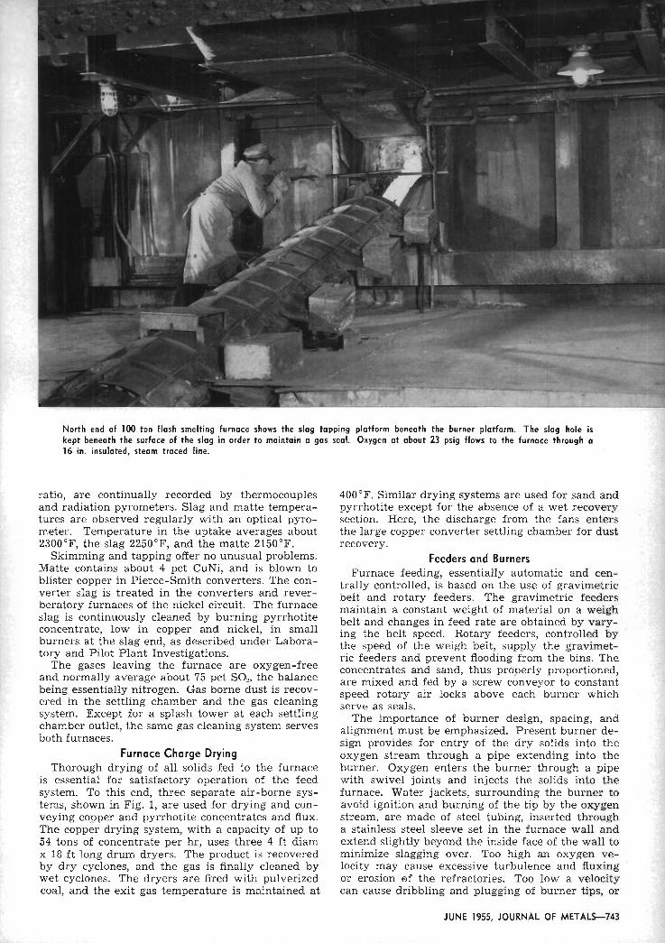
North end of 100 ton flash smelting furnace shows the slag tapping platform beneath the burner platform. The slag hole is kept beneath the surface of the slag in order to maintain a gas seal. Oxygen at about 23 psig flows to the furnace through a 16 in. insulated, steam traced line.
ratio, are continually recorded by thermocouples and radiation pyrometers. Slag and matte tempera- tures are observed regularly with an optical pyro- meter. Temperature in the uptake averages about 2300°F, the slag 2250°F, and the matte 2150°F.
Skimming and tapping offer no unusual problems. Matte contains about 4 pct CuNi, and is blown to blister copper in Pierce-Smith converters. The con- verter slag is treated in the converters and rever- beratory furnaces of the nickel circuit. The furnace slag is continuously cleaned by burning pyrrhotite concentrate, low in copper and nickel, in small burners at the slag end, as described under Labora- tory and Pilot Plant Investigations.
The gases leaving the furnace are oxygen-free and normally average about 75 pct SO,, the balance being essentially nitrogen. Gas borne dust is recov- ered in the settling chamber and the gas cleaning system. Except for a splash tower at each settling chamber outlet, the same gas cleaning system serves both furnaces.
Furnace Charge Drying Thorough drying of all solids fed to the furnace
is essential for satisfactory operation of the feed system. To this end, three separate air-borne sys- tems, shown in Fig. 1, are used for drying and con- veying copper and pyrrhotite concentrates and flux. The copper drying system, with a capacity of up to 54 tons of concentrate per hr, uses three 4 ft diam x 18 f t long drum dryers. The product is recovered by dry cyclones, and the gas is finally cleaned by wet cyclones. The dryers are fired with pulverized coal, and the exit gas temperature is maintained at
400°F. Similar drying systems are used for sand and pyrrhotite except for the absence of a wet recovery section. Here, the discharge from the fans enters the large copper converter settling chamber for dust recovery.
Feeders and Burners Furnace feeding, essentially automatic and cen-
trally controlled, is based on the use of gravimetric belt and rotary feeders. The gravimetric feeders maintain a constant weight of material on a weigh belt and changes in feed rate are obtained by vary- ing the belt speed. Rotary feeders, controlled by the speed of the weigh belt, supply the gravimet- ric feeders and prevent flooding from the bins. The concentrates and sand, thus properly proportioned, are mixed and fed by a screw conveyor to constant speed rotary air locks above each burner which serve as seals.
The importance of burner design, spacing, and alignment must be emphasized. Present burner de- sign provides for entry of the dry solids into the oxygen stream through a pipe extending into the burner. Oxygen enters the burner through a pipe with swivel joints and injects the solids into the furnace. Water jackets, surrounding the burner to avoid ignition and burning of the tip by the oxygen stream, are made of steel tubing, inserted through a stainless steel sleeve set in the furnace wall and extend slightly beyond the inside face of the wall to minimize slagging over. Too high an oxygen ve- locity may cause excessive turbulence and fluxing or erosion of the refractories. Too low a velocity can cause dribbling and plugging of burner tips, or
JUNE 1955, JOURNAL OF M E T A L S 7 4 3

!
. . ...... DTITi! COMCLMTRITC
0 I
- - - . . Fx l " N C R . . Tr'rlne sox
Fig. 1-Three separate air-borne systems are used for drying and conveying copper and pyrrhotite concentrates and flux. Dryers are fired with pulverized coal with exit gas temperature maintained a t 400°F.
pile-up of feed in the furnace below the burners.
Gas Cleaning System
Production of liquid sulphur dioxide from the furnace gas imposes a major gas cleaning and cool- ing problem rarely encountered in metallurgical operations, since a 75 pct SO, gas must be cooled through about 2200°F and cleaned to less than 0.003 grains of dust per cu ft. This is accomplished in three major steps, comprising: A-mechanical set- tling of dust and gas cooling by passage through a large, uninsulated, air-cooled settling chamber, B- countercurrent water scrubbing to clean and cool the gas to about 80°F without excessive loss of SO, to the scrubber water, and C-final treatment through a wet electrostatic precipitator for SO, removal.
The dust laden gases enter the settling chamber at about 2300°F. Here, a large part of the dust set- tles and the gas temperature drops to about 1200°F before entering the wet system. The gas flows through a water spray tower shown in Fig. 2 which is 4 f t in diam and 17 ft high, the sludge from which
Table I . Heat Evolved in Flash Smelting Process a t 1250°C
Constituent Kcal Pct
Matte 68 Slag 53 S On 38 Radiation loss 82
Total 241
drains to a 10 f t diam settling cone. The cone over- flow recirculates to the splash tower while cone underflow slurry is treated with lime to neutralize acid. The solids are recovered as filter cake.
The water saturated gas passes through three Venturi scrubbers in series, engineered by Sing- master & Breyer, New York, N. Y. The spray water flows countercurrent to the gas through the scrub- bing system and is cooled in heat exchangers be- tween each of the three stages. Final gas cleaning is by a wet Cottrell precipitator for removal of re- sidual SO, fume. The gas cleaning system is served by a 3600 rpm, 200 hp centrifugal fan rated at 4000 cfm at 115 in. W.G. at 105'F.
Corrosion by the strong, wet sulphur dioxide gas containing small amounts of SOa, and by the SO, saturated .solutions, is an ever present problem. However, type 316 stainless steel and lead provide satisfactory resistance. The splash tower, scrub- bers, cyclones, fans, circulating water pumps and discharge piping, heat exchanger tubes and all duct- work are of stainless steel, while the settling cone, standpipe, Cottrell precipitator and return water lines are of lead. The 16 in. diam 1500 f t line de- livering the cleaned gas to C.I.L. is also of stainless steel.
The cleaned gas is dried with sulphuric acid, then compressed and cooled to condense sulphur diox- ide. The liquid is drawn off to storage and the re- maining gas is further compressed and cooled to liquefy more sulphur dioxide. Following the sec- ond condensation, the tail gas is sent to the sul- phuric acid plant.
744-JOURNAL OF METALS, JUNE 1955

Fig. 2-Gas cleaning system is unique. In the production of liquid sulphur dioxide the 75 pct 502 gas must be cooled through about 2200°F and cleaned to less than 0.003 grains of dust per cu ft.
The entire operation is centrally controlled. Each burner is controlled by three instruments, two in- dicating, recording, and totalling concentrate and sand feed, the other, recording and totalling oxy- gen flow. Any one of eight abnormal conditions will shut off the oxygen and feed to all burners.
Furnace draft is regulated by a butterfly valve between the fan and the Cottrell, actuated by a re- cording controller. The furnace is operated at low draft to minimize air infiltration. Draft losses at various stages in the gas cleaning system are shown by a series of gages used to indicate build-up of sludge at any point.
Temperatures are recorded by pyrometers in the roof of the furnace and the sidewall of the uptake. Furnace temperature is controlled by minor adjust- ment of oxygen flow rate. Temperatures at specific locations in the roofs, bottom and side walls of the furnacc and temperatures of the gas and circulat- ing water in the gas cleaning system are measured by a 36-point indicating pyrometer.
The furnace exhaust system has three outlets as follows:
A-16 in. line to the C.I.L. liquefaction and acid plant.
B-bypass to the converter flue from the deliv- ery line situated between the furnace scrubber sys- tem and the C.I.L. plant. The bypass automatically opens if abnormal delivery pressure develops in the line.
C-bell damper arrangement from the settling chamber to the converter flue. The damper is oper- ated from the control room and is used to bypass the furnace gases during periods of cleaning or re-
pairs to the scrubbing system or when the furnace is being heated.
The volume of gas to C.I.L. is measured by a to- tallizing flowmeter and the SO? content is continu- ously recorded.
Oxygen Plant The Copper Cliff L'Air Liquide Oxyton oxygen
plant, third largest in the world, produces 325 tons per day of 95 pct oxygen, corresponding to 2 2/3 billion cu ft of oxygen per year or three times the production of all the cylinder oxygen plants in Canada. The Oxyton commenced production in January 1952, and has given excellent performance. Since temperatures as low as -300°F are involved, embrittling most ferrous metals, certain parts of the plant were made from a special Inco developed 8.5 pct nickel steel.
Fig. 3-Flash smelting furnace diagram proposed by Bridgman is reproduced from U. 5. Patent 578,912 dated Mar . 16, 1897.
JUNE 1955, JOURNAL OF METALS-745

I n I L a
I VI
FLUX 8 OXYGEN VS M A T T E GR&O,J)EI I I I I I
30, 40. 5 0 6 0 7 0 8 0 MATTE GRADE % Cu Ni
Fig. L O x y g e n requirement as percent of copper concen- trate for given matte grades and sand required as percent of copper concentrate to produce various matte grades and 35 pct SiOl slag are shown.
Oxygen plant operation is automatic once the liquefaction process has been started. Control and metering are carried out by some forty centralized control instruments. About 30,000 scfm of air is compressed to 68 psig in a turboblower, water- scrubbed, and sent through reversing regenerators where the carbon dioxide and water are frozen out. The resulting cold air, near its dew point, is then passed directly to a high pressure rectification col- umn. Necessary refrigeration is supplied by ex- panding some of the gas through a turbo-expander, simultaneously generating power. Rectification of the liquid air is effected in three columns working at 5, 2.5 and 1.2 atm absolute respectively, thereby effecting separation of oxygen from nitrogen. The gaseous oxygen produced is then carried 6000 f t in a 16 in. diam elevated pipeline to the oxygen flash smelting furnace.
6 0 'I
5 0
4 0
3 0
! 1 MATTE GRAOE VS
20
Fig. %Weights of furnace products per 100 Ib of copper concentrate are graphed as a function of matte grade.
V) 0 z
No storage facilities are provided but the demand for oxygen at the flash smelting furnace is rela- tively constant. The pressure in the pipeline to the furnace is controlled at 25 psig and excess oxygen is bypassed.
History of Process
I
There have been numerous proposals during the past half-century for smelting fine sulphide ores in suspension but, until recently, none of these plans for flash smelting has been commercially success- ful. In 1897, H. L. Bridgman; with remarkable pre-
3 10 0 3 0 b
4 0 5 0 6 0 7 0 8 0
MATTE GRADE % Cu Ni
science suggested the reverberatory furnace shown in Fig. 3 for the flash smelting of sulphide ores "by means of the heat generated by their own combus- tion" and by feeding the ore "as a spray of dust into the . . . strongly oxidizing atmosphere of a furnace chamber." J. H. Klepinger, M. W. Krejci, and C. R. Kuzell~ecommended the use of preheated air in the process.
AND ITS DISTRIBUTION
I200 , I I
3 0 4 0 5 0 60 7 0 8 0
MATTE GRAOE % Cu NI
Fig. M e a t of combustion in Btu's per Ib of copper con- centrate and the distribution of that heat between the fur- nace products and furnace losses ore shown.
In 1931, Frederick Laist and J. P. Cooper" carried out experiments along the lines of the later devel- opment at the Harjavalta smelter of Outokumpu Oy, Finland. The Laist-Cooper system consisted of a shaft furnace mounted over a reverberatory fur- nace for suspension roasting and smelting of cop- per concentrates.
Norman4 recommended the use of oxygen or oxy- gen-enriched air for autoge'nous flash smelting of copper and copper-nickel concentrates. His calcula- tions indicated that oxygen flash smelting could be economically attractive.
A number of others, including Chase, Freeman, Vanyultov, Zeisberg, and H a g l ~ n d , " ~ ~ ' , ~ ~ " have de- scribed related procedures, including the use of oxygen or oxygen-enriched air for roasting and pro- duction of sulphur dioxide, the use of auxiliary oil burners, and the use of oxygen or oxygen-enriched air to produce molten iron oxides from pyrite.
In the past decade autogenous flash smelting was independently developed both at the Copper Cliff smelter of the International Nickel Co. of Canada, Ltd.,'o.u and at the Harjavalta smelter of Outo- kumpu Oy, Finland."," In the former operation
746JOURNAL OF METALS, JUNE 1955

Controt room for the 1000 ton flash smelt- ing furnace contains instruments for con- trolling and record- ing pertinent data of the furnace op- eration.
oxygen is used to smelt the sulphides whereas in the latter the combustion air is preheated by heat exchange with the exit gases. Inco began mini-plant tests on oxygen flash smelting in 1945, pilot plant studies in January 1947, and commercial operation on an autogenous basis in January 1952. The Outo- kumpu Oy started pilot plant studies in February 1947, and semiautogenous commercial operations in 1949. The processes meet the economic requirements of their res~ective localities. In Finland hvdroelec- tric power cost, following annexation of territory by the USSR, is too high to permit production of low cost oxygen and there is a good market for sul- phuric acid. On the other hand, Inco hydroelectric power cost in northern Ontario permits production of low cost oxygen and there is a good market for liquid sulphur dioxide.
Two essentials in the development of the Inco low cost oxygen and there is a good market for sul- process, low cost oxygen and conversion of the fur- nace exhaust gas to liquid sulphur dioxide, were provided by the Canadian Liquid Air Co.'"" and Canadian Industries Ltd.,'o respectively.
In general, the oxygen flash smelting process in- volves drying the sulphide concentrates, and flux, and injecting them with oxygen into the smelting furnace to produce matte, slag, and a gas containing about 75 pct SO,. The gas is water-scrubbed and treated by a wet Cottrell before delivery to the Canadian Industries' plant. Production of liquid sulphur dioxide involves drying, compressing and cooling the cleaned gas. The liquid sulphur dioxide is used almost entirely in the preparation of cooking acid by sulphite pulp mills within a radius of 400 miles of Copper Cliff. Such use of liquid sulphur dioxide, in place of sulphur burning, has proven most satisfactory."
almost equals that obtained by sulphur oxidation. The primary matte contains about 50 pct copper, approximating Cu,S.FeS, but is diluted to a lower copper content when pyrrhotite is burned for slag cleaning. This novel method of cleaning the copper- rich slag by flash smelting pyrrhotite at the skim- ming end of the furnace is an important feature of the Inco process. Siliceous flux is used for slag formation. Principal reactions may be expressed as follows:
2CuFeS,+2Y'OC+Cu,S-FeS+2SO,+FeO [l] -AH, = 179 kcal
FeS + 0.75 0,+ 0.5 FeS + 0.5 FeO + 0.5 SO, [2] -AH?.. = 56 kcal
1.5 FeO + 0.75 SiO, + 0.75 ( 2 FeO.Si0,) -AH, = 6 kcal
131
Cu,O + FeS + Cu,S + FeO [41 Some copper is oxidized and is dissolved in the
slag, probably as Cu,O, and some copper sulphide is both dissolved in the slag and suspended as matte prills. On burning pyrrhotite according to Eq. 2, the matte prills and dissolved copper sulphide are washed from the slag by molten iron sulphide drop- lets, and the oxidized copper is reduced according Eq. 4 resulting in a slag lower in copper. Since rela- tively little copper oxide is involved in this reduc- tion, its effect on the overall heat balance is negligible.
The total heat evolved in smelting chalcopyrite
- - -
Table 11. Comparison Between Pilot Plont Flash Smelting and Conventional Reverberatory Smelting, Pct
S l a ~ Matie
Item CuNi CuNi 8 1 0 2
Thermal Considerations Copper concentrate and sand flux, without slag cleaning 57.7 0.74 34.4
In the furnace, the oxygen combines with some C o ~ , " ~ , r $ ~ ~ ~ ~ ~ $ , " , " ~ ~ n d 57.2 0.48 35.9
of the sulphur and iron of the chalcopyrite CuFeS,, St:;$;;z:;;;~d~;;;;;;;- 44.3 0.70 36.9
to form SO, and FeO. The heat from FeO formation
JUNE 1955, JOURNAL OF M E T A L S 7 4 7

Fig. 7-Diagram of first commercial flash smelting furnace shows construction details. Furnace was started up in January 1952 and treated 500 tons of sulphides per day.
and burning pyrrhotite as depicted 3 is 241 kcal. At 1250°C this heat shown in Table I.
by Eqs. 1, 2, and Laboratory and Pilot Plant Investigations is apportioned as Mini-plant tests on autogenous smelting of sul-
phides with oxygen were conducted in the Copper Cliff laboratories, using a horizontal gas-tight fur- nace, 12x15~48 in., fitted with an injection type burner. This furnace smelted up to 3 tons of con- centrate per day and produced 98 pct SO, gas. The matte contained about 5 pct Cu and the slag 0.45 pct Cu. With these encouraging results, and with the prospects of obtaining low cost oxygen and markets for the sulphur products, a pilot plant investigation was undertaken.
The pilot plant was designed to smelt 20 tons per day of sulphide concentrates with oxygen (95 to 99 pct 0,) from a 5-ton per day plant. The furnace, initially 8 ~ 2 ~ 2 % ft high inside, consisted of gas- tight welded steel shell with insulation between the shell and the refractory lining. The furnace and dust settling chamber were modified several times, and various refractories and methods of insulation were tried. The final pilot plant furnace measured
Fig. &Section A-A' through flash smelting furnace 1 5 x 4 ~ 4 ft high at the skewbacks and had a capacity shows the gas tight welded steel casing which encloses of about 25 tons of concentrates per day. Refrac- the furnace. tories which gave satisfactory service were forsterite
748-JOURNAL OF METALS, JUNE 1955

roof and magnesite walls and bottom. The furnace was preheated with oil but thereafter operation was autogenous by burning of the sulphides with oxygen. Temperatures were measured by optical pyrometer as thermocouple wells were attacked.
Mini-plant operation had demonstrated the ne- cessity of a dry, properly proportioned, and uni- formly fed charge. To provide for such conditions in the pilot plant, sulphide concentrates and flux were dried, ground, and transferred to separate bins at the furnace. Feed from each bin was then con- trolled by an integrating gravimetric belt-type feeder and conveyed to a mixing and sealing feeder discharging to the burner. Oxygen, delivered to the burner at 10 psig, injected the solids into the furnace.
Skimming and tapping offered no unusual prob- lems but gas cleaning prior to delivery to the Canadian Industries Ltd. liquefaction pilot plant required considerable development. Slag was skimmed from the end of the furnace opposite the burner, and matte was tapped either from the same location or from the side of the furnace. After con- siderable revision, gas was cleaned by passage through a settling chamber, a water spray scrub- ber, a wet cyclone, and a baghouse equipped with fiberglass bags. Draft for the gas recovery system was supplied by a high-speed fan which delivered the cleaned sulphur dioxide gas under pressure to the Canadian Industries Ltd. liquefaction pilot plant. A Leeds & Northrup sulphur dioxide ana- lyzer-recorder was connected through a drier and filter to the blower outlet. When using oxygen of 95 pct purity, the furnace gases contained 80 to 90
South end of the platform shows the burner platform of the 1000 ton flash smelting furnace. Feed pipes extend from the burners up to the rotary air locks above and up to the aravirnetric feeders on the umer floor.
~ , . ~
pct SO,, the balance being mainly nitrogen. flux with lime and other slag-modifying agents; B- The pilot plant operated for about two Years and slag cleaning with pyrrhotite concentrate; c - ~ d -
treated over 7000 tons of concentrates. Most of this dition of converter slag to the furnace; and ~ - ~ h ~ time was spent on flash smelting of regular copper smelting of higher grade sulphide concentrates to and nickel concentrates. Some of the specific items produce higher grade mattes, white metal, and me- tested were as follows: A-Use of sand or quartzite tallic copper. Various injection burners were used,
CXCLO.IO* HLCK VALVE
-- - cbftl!* . .
SAUO COMCEMTRATE
P Y # * R O T I T E SAM0 COUCCUTIATL
Y C L L . C O * " t l O l
5 L R C I C O * V C I O l
I O T b R V S L A L
-a! A . .:
-.
C? 1 - 7 . ~ . 70 COIIC. , , v l r r c COIIL~TI.~ : -i L ~ C L L
i .. T R A N 8 P L I Can
Fig. 9-During one month the daily furnace charge averaged 520 tons of copper concentrate, 97 tons of pyrrhotite concentrate, and 87 tons of sand flux. Oxygen averaged 128 tons per day or 20.8 pct of the sulphides treated.
JUNE 1955, JOURNAL OF M E T A L S 7 4 9

Table Ill. Pilot Plant Data With No Pyrrhotite Used For Slag Cleaning
Item Data
Assay of copper concentrate CuNi Fe
Si02 Slag produced, SiO? Sand flux, SiO? Feed temperature Matte temperature Slag and gas temperature
31.5 pct 30.7 ~ c t 33.3 pct
1.9 pct 35.0 pct 79.0 pct 50°F
2050°F 2250°F
and the oxygen purity was varied between 95 and 99.5 pct.
Slag losses from both nickel and copper concen- trates were lower than those of conventional re- verberatory practice, in spite of higher matte grades and such losses were substantially decreased by flash smelting pyrrhotite concentrate in the furnace before skimming. Typical results for copper are shown in Table 11.
The results of the pilot plant campaign fully confirmed the indications from the mini-plant stud- ies that the oxygeh flash smelting process was sound, and demonstrated that, under appropriate conditions, sulphide concentrates containing over 15 pct S could be flash smelted autogenously with oxygen more economically than by normal re- verberatory practice.
Pilot plant data used for the design of the first 1 commercial furnace are shown in Figs. 4, 5, and 6.
These apply for the conditions shown in Table I11 when no pyrrhotite is used for slag cleaning. In the commercial operation, using pyrrhotite, matte grades are lower.
First Commercial Furnace Immediately following completion of the pilot
plant investigations in 1949, work began on a com- mercial furnace to treat 500 tons of sulphides per day. However, slow deliveries delayed start-up until January 1952. The furnace is shown in Figs. 7, 8, and 9. A short cross flue, not shown, connects the uptake to a settling chamber. The upper sections of the furnace walls and uptake were tied to the fur- nace shell with steel strips imbedded in the brick joints. An opening in the roof of the uptake was used to vent furnace gases when heating with oil or to bypass the gas cleaning system when maintenance was required.
The settling chamber, of welded steel plate, was 40 f t long, 16 f t wide, and 17% f t high. The cross flue from the furnace uptake and the walls and roof of the settling chamber directly opposite the uptake were lined with firebrick. Fins were welded to the outside of the walls and roof and were covered to form ducts through which air was blown to increase gas cooling before scrubbing and to cool the steel plate. Two parallel hoppers at the bottom of the
Table IV. Heat Distribution in the 500 Ton Furnace, Pct
Heat to the matte and slag 57 Heat radiated from furnace walls, roof and uptake
including water jackets 26 Heat radiated from settling chamber. including flue dust 9 Heat removed by heat exchangers in gas cleaning 7 Heat in gases to C.I.L. saturated 100°F 1
settling chamber collected the flue dust and dis- charged i t by a screw conveyor through air locks to conveyors and thence to the sand dryer for re- treatment.
Although initially there was considerable diffi- culty with such items as feeders and gas-cleaning equipment, the technical and economic success of the project was never in doubt. During one month the daily furnace charge averaged 520 tons of c ~ p - per concentrate, 97 tons of pyrrhotite concentrate and 87 tons of sand flux. Oxygen averaged 128 tons per day or 20.8 pct of the sulphides treated. Daily production, excluding flue dust and slimes, averaged 310 tons of matte containing 45.4 pct CuNi and 284 tons of slag containing 38 pct SiOz and 0.76 pct CuNi. Gases leaving the furnace carried about 100 tons of SO, per day.
High smelting rates were responsible for rather severe refractory attack, the strongest attack being on the side walls above the slag line, especially be- low the uptake. Deterioration of the roof was great- est near the uptake, and the uptake arches were also fluxed and eroded. There was, however, no notice- able attack on the furnace bottom. To decrease flame erosion of the roof and side walls, the original fur- nace was modified to provide a sloping roof with a rise of approximately 3 f t from the ends of the fur- nace to the bottom of the uptake, and the burners a t each end of the furnace were brought 1 f t closer together. Heat loss from the furnace was also in- creased by removing the insulation between the re- fractory brick and the steel shell, by welding fins to the furnace shell a t 10 in. centers, and by insert- ing copper water jackets in the refractory lining of the furnace in the uptake area. The rate of fluxing of magnesite and forsterite brick by oxides increases rapidly above 2450°F and constant care was re- quired to avoid high flame temperatures. Heat dis- tribution in the 500 ton furnace is given in Table IV.
References 'H. L. Bridgman: U. S. Patent 578,912, Mar. 16,
1897. ' J. H. Klepinger, M. W. Krejci, and C. R. Kuzell:
U. S. Patent 1,164,653, Dec. 21, 1915. ' F. Laist and J. P. Cooper: Trans. AIME (1933) 106,
DD. 104 to 110. - - T. E. Norman: Eng. & Min. Jour. (1936) 137, pp. 499
to 502. 'M. F. Chase, F. E. Pierce, and J. Skogmark: U. S.
Patent 1,447,645, Mar. 6, 1923. W. Freeman: Can. Min. & Metall. Bulle t in (1930)
23, pp. 471 to 476. V. A. Vanyukov: T z v e t n u y e Metal ly (1930) pp. 365
to 376. 'F. C. Zeisberg: U.S. Patent 2,086,201, July 6, 1937. 'T. R. Haglund: U. S. Patent 2,209,331, July 30, 1940. 'OR. C. Stanley: Annual Address to Shareholders,
International Nickel Co. of Canada, April 1948. " J. R. Gordon, G. H. C. Norman, P. E. Queneau,
W. K. Sproule, and C. E. Young: Canadian Patent 503,- 466, June 1, 1954; U. S. Patent 2,668,107, Feb. 2, 1954. *P. Bryk: Misc. Publication No. 435 (December
1951) British Non-Ferrous Metals Research Assn. * F. Benitez: Eng. and Min. Jour. (1953) 154, pp. 76
to 80. " J. Grunberg: Ind. Chemis t (1950) 26, pp. 61 to 66. =J. R. ~ u ~ i l l : Chemis t ry in ~ a n a d a (i952) 4, pp.
172 to 178. '@ R. W. Allgood: Can. Min. & Metall. Bulle t in (1952)
p. 153. l7 R. D. i itch field: Pulp Paper Mag., Canada (1954)
55, pp. 247 to 252.
7 5 J O U R N A L OF METALS, JUNE 1955