journal of science protection coordination practice in
TRANSCRIPT
*Corresponding author, e-mail: [email protected]
GU J Sci 30(4): 180-198 (2017)
Gazi University
Journal of Science
http://dergipark.gov.tr/gujs
Protection Coordination Practice in Electrical Substation Part-1
Overcurrent and Earth Fault Protection - Case Study of Siddik Kardesler
Substation (SKS), Istanbul, Turkey
Abdulfetah SHOBOLE1, Mustafa BAYSAL
2, Mohammed WADI
3, Mehmet Rida TUR
4*
1,3 Electrical & Electronics Engineering Department, Istanbul Sabahettin Zaim University, Halkalı Mahallesi, Halkalı Caddesi, Halkalı Kampüsü No:2, 34303 Küçükçekmece, Istanbul, Turkey
2 Electrical Engineering Department, Yildiz Technical University, Davutpaşa St., 34220 Esenler, Davutpasa, Istanbul, Turkey
4Electrical Engineering Department, Mardin Artuklu University, Diyarbakır St. Yenişehir Campus, Mardin, Turkey
Article Info
Abstract
Protection coordination is the heart of all power systems. To ensure a quality and reliable
operation of the power systems, an electrical fault must be cleared within a short time. This can
be achieved by proper coordination between the protection relays. In Siddik Kardesler
Substation the MV voltage feeders’ protection is provided by overcurrent relays. This paper is
principally concerned with practical protection coordination of the electrical substation by
using Siddik Kardesler Substation substation as a case study. In the Part-2, distance and
differential protection will be discussed. Finally, after test and commissioning, the substation is
successfully energized without a problem.
Received: 26/12/2016
Accepted:14/08/2017
Keywords
Earth Fault Protection
Over Current Protection
Protection Coordination Electrical Substation
1. INTRODUCTION
The power system is among very complex systems which consist of many expensive types of
equipment. Especially, Electrical Substations (ESS) are among the critical components of the power
system and the availability of a power system is based on their performance. For example, the
switching and fault clearing actions of power systems are performed by the ESS. ESS are
interconnected by transmission line to make the power system meshed or networked increasing the
reliability [1]. Thus, they represent a huge capital investment which has to be operated securely and
reliably to minimize the payback period.
Some of the roles of substations in power systems are [2, 3]:
• Stepping up the voltage at generating stations to high voltage levels (generating station);
• Changing between the voltage levels within the high-voltage system (system stations);
• Stepping down to a distribution or medium-voltage level. (distribution stations);
• Interconnect the same voltage levels and etc.
Substations can be either Air Insulated (AIS), Gas Insulated (GIS), compact or hybrid based on [3],
the function and location of the power supply, environmental and climatic conditions, specific
requirements regarding the locations, and cost and space limitations. A GIS uses sulfur hexafluoride
(SF6) to provide insulation while the AIS uses atmospheric air [3, 6]. GIS is more compact structure,
reliable and requires less maintenance compared to AIS. In addition, the service life of GIS is longer
compared to AIS. But GISs are expensive than AIS and mostly used where space is expensive or not
available.
As an important component of power systems, substations are required to operate safely all through
their lifetime. The arc-current generated during fault can burn and weld copper conductors of
transformer and machines’ core laminations in a very short time [6]. In addition, the insulation may
break down, causing the flow of current between phases or phase to ground. Consequently, an
adequate protection system which detects faults and disconnects elements of the power system during

181 Abdulfetah SHOBOLE, Mustafa BAYSAL, Mohammed WADI, Mehmet Rida TUR / GU J Sci, 30(4): 180-198 (2017)
a fault is an essential design subject of the power system. The protection system cannot prevent the
occurrence of the fault, but they should act immediately after the occurrence of the fault. The
protection system is an arrangement between protection equipment (like relays, fuses, etc.) and other
devices (like transformers, circuit breakers, batteries, etc.) which are vital to accomplishing a specified
function depending on the protection principles applied [6].
This paper is concerned with the protection coordination (ProC) study of Siddik Kardesler Substation
(SKS) which is an AIS type. The protection study is planned to be presented in two parts (Part-1 and
Part-2) the first part is concerned with over current and EFPs of the SKS. The second part is concerned
with the differential and distance protection aspects of the SKS. This paper (Part-1), is outlined as
follows; the components of the SKS and its protection arrangements will be discussed in sections 2
and 3 respectively. The important over current relay characteristics will be discussed in section-4. The
overcurrent coordination study of SKS with necessary procedures will be discussed in section-5.
Finally, the EFP will be discussed in section-6.
2. COMPONENTS OF THE SKS
The SKS consists of 154 kV and 34.5 kV components that serve numerous purposes. Components like
circuit breakers, isolators, current transformers (CTs), surge arrestors, power transformers, meters,
control, relay equipment and etc. are shown symbolically upon the substation’s single line diagram as
shown in Figure 1. In Tables 1 and 2 brief descriptions of these components are provided.
Table1. Components of Substation (154 kV)
154 kV components of substation
Code Name Description
1/1A Voltage Transformer Used to convert the voltage from HV to the level that can be
used for protection, control, automation devices and etc.
2 Lin Traps Used for Power Line Carrier (PLC) Communication.
3/3A Current Transformer Used to convert from very high current to the level that can be
used for protection, control, automation devices and etc.
4T Isolator with Grounding
blade
For no load opening and closing, and isolate the downstream
device to be worked on. The grounding blade is used to ground
the isolated part for more safety.
5 Circuit breaker Make and break all currents within the scoped of their rating.
5T Circuit Breaker with
Auto-reclosing
Circuit breaker with auto-reclosing capability.
4 Isolator For no load opening and closing, and isolate the downstream
device to be worked on.
6 Surge Arrester To discharge high voltages caused by lightning strikes or
switching operations and earth faults.
7 Power Transformer To transform the voltage level from 154 kV to 34.5 kV.
Table 2. Components of Substation (34 kV)
34 kV Components of the Substation Code Name Description
8c/8b/8c Cable Medium Voltage (MV) XLPE underground cable for
transporting the energy.
6a Surge Arrestor MV surge arrestor.
5a/5b/5c Circuit Breaker MV circuit breaker.
3a/3b/3c Current Transformers MV current transformer.
14 Voltage Indicator Indicates the availability of voltage on each phase.
4t Grounding Switch Used to ground the isolated part for more safety.
10 Voltage Transformer MV voltage transformer.

182 Abdulfetah SHOBOLE, Mustafa BAYSAL, Mohammed WADI, Mehmet Rida TUR / GU J Sci, 30(4): 180-198 (2017)
ÇOLAKOĞLU SUBSTATION
154/34.5kV 125(150) MVA
1272MCM
5T
4
(Phase A)
1
MAIN BUSBAR
TRANSFER FEEDER
4
3
67/67N
RE LAY PANEL
CO NTRO L PANEL
WA3 2
2
mA
W1
mA
VA r
VA r1
V1
1
SYNC.
Vk
3
mA
A
3
GEBZE OSB SUBSTATION
154kV
M
M
M
M
MM
M
M
M
M
M
1272MCM
21 21N 25
10kA34.5kV
51N
GROUNDING TRANSFORMER
TCR.
& 2
. HA
RM
ON
IC F
ILT
ER
INPUT
POTA
FU
RNA
NC
E
AUX. TRANS.
34.5 kV, 50 Hz, 25 kA, 2500 A METAL CLAD
H01 H02 H03 H04 H05 H06 H07
ARC
FU
RN
AN
CE
87T
RELAY PANEL
Wh Varh
M ain Energy M eter
Varh
Spare Energy Meter
Wh
CONTROL PANEL
WA3 1
1
mA
W1
mA
VA r
VAr1
V1
1
SYNC.
Vk
3
mA
A
50 51 50N 51N
METERING PANEL
Diff. P
rotectio
n
Power Quality
67/67N
RE LAY PANEL
CO NTRO L PANEL
WA3 2
2
mA
W1
mA
VA r
VA r1
V1
1
SYNC.
Vk
3
mA
A
3
M
M
M
M
21 21N 25
4
4
4T
3
2
1
5
4
3A
61A
7
8C
6a
5T
4
4
4
4
4T
3
2
1
5
1
4t14
10
11 5b 5a 5a 5a
14 14 14 14 14
3a 3b 3c 3c 3c
5c
12
8a
4t 4t 4t 4t
8b 8c 8c 8c8c
TRANSFER BUSBAR
Meas. System
TRANSFORMER
3.&
4. H
AR
MO
NIC
FIL
TER
Figure 1. Siddik Kardeşler Substation Single Line Diagram.
3. PROTECTION ARRANGEMENTS OF THE SKS
In Figure 1 protection functions used in SKS are indicated by the American National Standards
Institute (ANSI) codes. Based on the single line diagram shown in Figure 1, the protection
arrangements for the SKS are as follow:
1. For the 154 kV incoming transmission lines, distance protection (21/21N), directional OCP
(67/67N) and frequency protection (25) are implemented.
2. Differential protection (87T), over current and earth fault protections (50/51/50N/51N) are
implemented for the power transformer.
183 Abdulfetah SHOBOLE, Mustafa BAYSAL, Mohammed WADI, Mehmet Rida TUR / GU J Sci, 30(4): 180-198 (2017)
3. For the MV outgoing feeders, over current and earth fault protections (50/51/50N/51N) are
implemented.
4. Auxiliary Transformer is protected by MV fuse.
4. CHARACTERISTICS OF OVERCURRENT PROTECTION RELAY
4.1. Selectivity
The protection relays have to operate in a way that should provide adequate selectively by isolating the
fault through opening the circuit breakers. This requires coordination of protection functions between
the protective relays. Time grading, current grading or unit protection methods are commonly used to
provide the required coordination between the relays.
In the time grading method, the protection relays in successive zones are arranged in time so that only
the relays near to the fault operate first. For this purpose, definite time relays are used and it is
independent of the level of fault current. However, as a disadvantage, the relay near to the source (with
highest fault level) clears the fault with longer time delay.
Current based grading takes the advantage of variation of fault current at different parts of the
network. The variation of impedance according to the location between the fault point and the source
is the main cause of the fault current variation. In order to use this approach; there must be an
appreciable impedance between the two relaying points.
To overcome the limitations of current based and time-based grading, the inverse time overcurrent
relay characteristic was developed. The inverse time characteristics are defined by standard curves. In
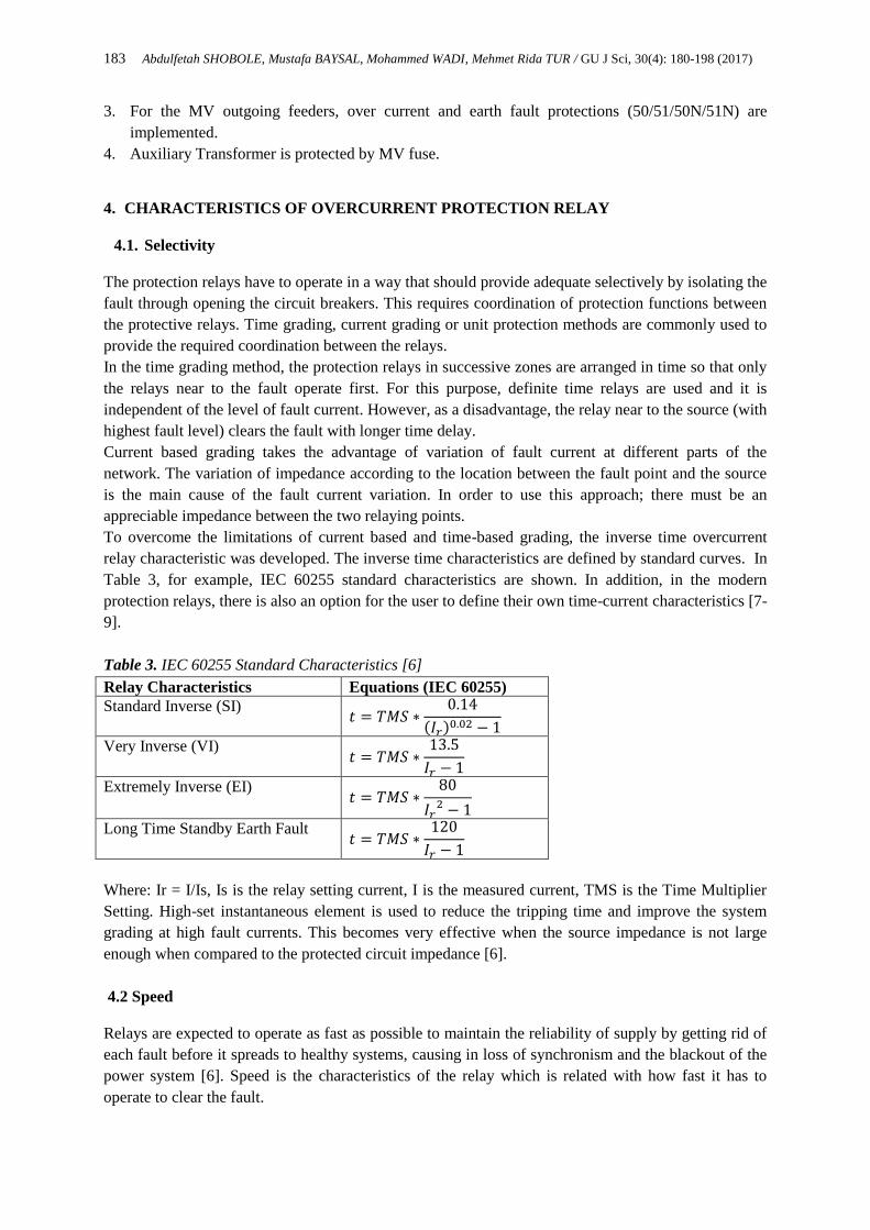
Table 3, for example, IEC 60255 standard characteristics are shown. In addition, in the modern
protection relays, there is also an option for the user to define their own time-current characteristics [7-
9].
Table 3. IEC 60255 Standard Characteristics [6]
Relay Characteristics Equations (IEC 60255)
Standard Inverse (SI) 𝑡 = 𝑇𝑀𝑆 ∗
0.14
(𝐼𝑟)0.02 − 1
Very Inverse (VI) 𝑡 = 𝑇𝑀𝑆 ∗
13.5
𝐼𝑟 − 1
Extremely Inverse (EI) 𝑡 = 𝑇𝑀𝑆 ∗
80
𝐼𝑟2 − 1
Long Time Standby Earth Fault 𝑡 = 𝑇𝑀𝑆 ∗
120
𝐼𝑟 − 1
Where: Ir = I/Is, Is is the relay setting current, I is the measured current, TMS is the Time Multiplier
Setting. High-set instantaneous element is used to reduce the tripping time and improve the system
grading at high fault currents. This becomes very effective when the source impedance is not large
enough when compared to the protected circuit impedance [6].
4.2 Speed
Relays are expected to operate as fast as possible to maintain the reliability of supply by getting rid of
each fault before it spreads to healthy systems, causing in loss of synchronism and the blackout of the
power system [6]. Speed is the characteristics of the relay which is related with how fast it has to
operate to clear the fault.

184 Abdulfetah SHOBOLE, Mustafa BAYSAL, Mohammed WADI, Mehmet Rida TUR / GU J Sci, 30(4): 180-198 (2017)
4.3 Sensitivity
Additionally, relays must be sensitive enough to identify minimum operating fault level (current,
voltage, power etc.).
4.4 Reliability
Furthermore, protection relays are required to be highly reliable, by reducing the risk of failure to trip
(dependability) and risk of over tripping (security).
4.5 Directionality
For the parallel feeders, line with two end feeds and ring networks, the OCP cannot provide
selectivity. Therefore, directional control facility can be included to the protection relays to provide
better selectivity [10]. To determine the direction of the fault current, voltage data is required. The
connection of the voltage and current information to the relays depends on the phase angle between
the voltage and current to be applied to the relay at unity system power factor [6]. In numerical or
digital relays, phase displacements can be obtained by software in contrast to electromechanical and
static relays in which the phase displacements are obtained by applying the voltage and the current
inputs to the relay [11-12].
The commonly used standard connection for the relays is 90° Quadrature Connection [6]. In this type,
two forms of connections are available based on the Relay Characteristic Angle (RCA). The RCA is
the angle by which the voltage applied to the relay is shifted to produce maximum sensitivity to the
relay. These connections are:
4.5.1 90°-30° Characteristic (30° RCA)
This is obtained by connecting the Phase-A current (Ia) to the phase-A relay element and the Vbc
voltage is displaced by 30o in a counter-clockwise direction. In this connection type when the current
lags the phase to neutral voltage by 60o the maximum sensitivity will be produced. The correct
directional tripping can be obtained for current angle 30o leading to 150o lagging; as shown in Figure
2 (a).

185 Abdulfetah SHOBOLE, Mustafa BAYSAL, Mohammed WADI, Mehmet Rida TUR / GU J Sci, 30(4): 180-198 (2017)
MTA
V�bc
Vbc
Vb
Vc
Va
Ia
Zero torque line
(a)
MTA
V�bc
Vbc
Vb
Vc
Va
Ia
Zero torque line
(b)
Figure 2. (a). Vector Diagram for the 90o-30o Connection, (b). Vector Diagram for the 90o-45o
Connection
4.5.2 90°-45° Characteristic (45° RCA)
In this case, phase-A current (Ia) is connected to the phase-A relay element and Vbc is shifted by 45o
in a counter-clockwise direction. In the SKS directional over current and EFP (67/67N) are used as the
backup protection for the distance relay (21/21N) [10]. The maximum sensitivity is produced for the
45o current lagging from system phase to neutral voltage. The correct directional tripping zone is from
45o leading to 135
o lagging as shown in Figure 2 (b).
5. OVERCURRENT PROTECTION COORDINATION STUDY
The coordination study between overcurrent relay requires the following data [6, 12, and 13]:
1. The single line diagram of the system with rating and type of protection system specified on it.

186 Abdulfetah SHOBOLE, Mustafa BAYSAL, Mohammed WADI, Mehmet Rida TUR / GU J Sci, 30(4): 180-198 (2017)
2. The impedance of power system components like cables, transmission lines, transformers, rotating
machines and etc.
3. The minimum and maximum short circuit currents estimated to flow through each of the protection
relays.
4. The maximum load current through each of the protection device.
5. Starting currents of different types of motors.
6. The thermal withstands, transformer inrush, and damage characteristics curves.
7. The curve showing generators’ fault current rate of decay.
8. The current transformers’ performance curves.
5.1 Fault Current
For the protection relay coordination, distribution of the fault current throughout the network has to be
known. Especially the minimum and the maximum short circuit currents have to be calculated through
each relaying points. Short circuit fault study for the coordination of protection relays in the practical
application involves the following steps [6]:
1. Identifying the possible operating conditions and stability limits by using network diagram and
available data.
2. Calculating minimum and maximum fault currents for each type of fault through each relaying
points.
3. Calculating the fault current distribution in the network, especially through each relaying point.
Based on the above steps, the protection system and the classes of protection, such as high or low have
to be determined. During the occurrence of the fault in power system, the three-phase current and
voltage are no more balanced except in three phase short circuit faults. Therefore, the protection
engineer is concerned with symmetrical faults and asymmetrical faults involving phase-to-phase and
one or two phases to earth faults [8, 13].
For the analysis of unbalanced fault conditions, balanced symmetrical components are used.
Symmetrical components can also be used to detect different types of faults and differentiate between
the faults. For example, zero sequence and negative sequence voltages and currents are used mostly in
non-directional or directional earth fault OCPs settings. In this study, the analysis of symmetrical
components will not be discussed. However, the symmetrical components (voltage and current) which
are available in different type of faults are summarized in Table 4.
Table 4. Symmetrical Components and Fault Types
Sequence
Currents
Single
Phase to
Earth Fault
Phase-
Phase
Fault
Phase-Phase
to Earth
Fault
Three
Phase
Fault
Three Phase
to Earth
Fault
I1 x x x x x
I2 x x x
I0 x x
Turkish electricity transmission corporation (TEİAŞ) publishes the maximum and minimum short
circuit currents and power each year. The short circuit currents which are taken from the published
data [14] for ‘Gebze Industrialized Zone’ as well as ‘Çolakoğlu Substations’ are summarized in Table
5. These values are used in the short circuit analysis of the SKS. In this study, the short circuit analysis
is realized by using the ETAP power system analysis software. The impedance data of the line, cable,
and transformer used in this study can be referred as systems data. Based on these data and the short
circuit current from the network side, the short circuit analysis is conducted and the results are
summarized in Table 6. The fault current will decrease from the TEİAŞ 154 kV towards the 33 kV
187 Abdulfetah SHOBOLE, Mustafa BAYSAL, Mohammed WADI, Mehmet Rida TUR / GU J Sci, 30(4): 180-198 (2017)
side as shown in Table 6. The software can calculate the maximum and minimum fault current through
each relaying points based on the IEC 60909 method or other standards. For this study, IEC 60909
method is used.
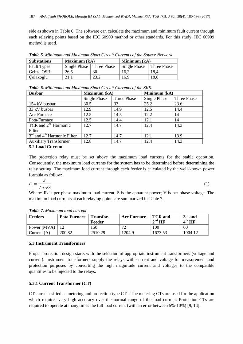
Table 5. Minimum and Maximum Short Circuit Currents of the Source Network
Substations Maximum (kA) Minimum (kA)
Fault Types Single Phase Three Phase Single Phase Three Phase
Gebze OSB 26,5 30 16,2 18,4
Çolakoğlu 21,1 23,2 16,9 18,8
Table 6. Minimum and Maximum Short Circuit Currents of the SKS.
Busbar Maximum (kA) Minimum (kA)
Single Phase Three Phase Single Phase Three Phase
154 kV busbar 30.5 33 25.2 23.6
33 kV busbar 12.9 14.9 12.5 14.4
Arc-Furnace 12.5 14.5 12.2 14
Pota-Furnace 12.5 14.4 12.1 14
TCR and 2nd
Harmonic
Filter
12.7 14.7 12.4 14.3
3rd
and 4th Harmonic Filter 12.7 14.7 12.1 13.9
Auxiliary Transformer 12.8 14.7 12.4 14.3
5.2 Load Current
The protection relay must be set above the maximum load currents for the stable operation.
Consequently, the maximum load currents for the system has to be determined before determining the
relay setting. The maximum load current through each feeder is calculated by the well-known power
formula as follow:
𝐼𝐿 =𝑆
𝑉 ∗ √3 (1)
Where: IL is per phase maximum load current; S is the apparent power; V is per phase voltage. The
maximum load currents at each relaying points are summarized in Table 7.
Table 7. Maximum load current
Feeders Pota Furnace Transfor.
Feeder
Arc Furnace TCR and
2nd
HF
3rd
and
4th
HF
Power (MVA) 12 150 72 100 60
Current (A) 200.82 2510.29 1204.9 1673.53 1004.12
5.3 Instrument Transformers
Proper protection design starts with the selection of appropriate instrument transformers (voltage and
current). Instrument transformers supply the relays with current and voltage for measurement and
protection purposes by converting the high magnitude current and voltages to the compatible
quantities to be injected to the relays.
5.3.1 Current Transformer (CT)
CTs are classified as metering and protection type CTs. The metering CTs are used for the application
which requires very high accuracy over the normal range of the load current. Protection CTs are
required to operate at many times the full load current (with an error between 5%-10%) [9, 14].
188 Abdulfetah SHOBOLE, Mustafa BAYSAL, Mohammed WADI, Mehmet Rida TUR / GU J Sci, 30(4): 180-198 (2017)
Current Transformer Ratio
The CTs has to be selected based on the maximum load current on the primary side and the maximum
secondary current under fault condition (generally, 100 times rated secondary current). Additionally,
the thermal withstand current during fault must be considered. Based on IEC 60255 standard, the
thermal withstand current of the current input has to be 100-times nominal current (100xIn). For
example, for the system with fault current of 25 kA, the lowest possible CT rated current must not fall
below 25 kA / 100 = 250 A. Consequently, the selection of the primary rated current of 300 A is
correct.
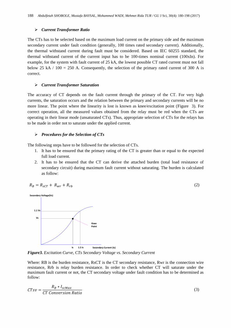
Current Transformer Saturation
The accuracy of CT depends on the fault current through the primary of the CT. For very high
currents, the saturation occurs and the relation between the primary and secondary currents will be no
more linear. The point where the linearity is lost is known as knee/excitation point (Figure 3). For
correct operation, all the measured values obtained from the relay must be red when the CTs are
operating in their linear mode (unsaturated CTs). Thus, appropriate selection of CTs for the relays has
to be made in order not to saturate under the applied current.
Procedures for the Selection of CTs
The following steps have to be followed for the selection of CTs.
1. It has to be ensured that the primary rating of the CT is greater than or equal to the expected
full load current.
2. It has to be ensured that the CT can derive the attached burden (total load resistance of
secondary circuit) during maximum fault current without saturating. The burden is calculated
as follow:
𝑅𝐵 = 𝑅𝑠𝐶𝑇 + 𝑅𝑤𝑟 + 𝑅𝑟𝑏 (2)
1.1 Vs
Vs
Is 1.5 Is
Secondary Voltage(Vs)
Secondary Current (Is)
Knee Point
Figure3. Excitation Curve, CTs Secondary Voltage vs. Secondary Current
Where: RB is the burden resistance, RsCT is the CT secondary resistance, Rwr is the connection wire
resistance, Rrb is relay burden resistance. In order to check whether CT will saturate under the
maximum fault current or not, the CT secondary voltage under fault condition has to be determined as
follow:
𝐶𝑇𝑠𝑣 =𝑅𝐵 ∗ 𝐼𝑠𝑐𝑀𝑎𝑥
𝐶𝑇 𝐶𝑜𝑛𝑣𝑒𝑟𝑠𝑖𝑜𝑛 𝑅𝑎𝑡𝑖𝑜 (3)

189 Abdulfetah SHOBOLE, Mustafa BAYSAL, Mohammed WADI, Mehmet Rida TUR / GU J Sci, 30(4): 180-198 (2017)
Where: CTsv is the CT secondary voltage and, IscMax is the maximum fault current.
The resulting value from equation (3) is plotted on the CT excitation curve and if it is below the knee
point of the CT there would be no saturation and if it is above the knee point there would be
saturation. Based on the above procedures, all the CTs in the SKS are determined.
5.3.2 Voltage Transformer (VT)
There are two types of voltage transformers which are used in power industry, namely electromagnetic
and capacitive voltage transformers. Electromagnetic voltage transformers are used for accurate
metering and used for lower level voltage applications. Capacitive voltage transformers are used for
high-voltage transmission line applications. It consists of coupling capacitors, compensating reactor,
step-down transformer and Ferro-resonance suppression circuit as shown in Figure 4.
C1
C2
L
Step Down Transformer
CompensatingReactor
Relay Voltage
Ferro Resonance Suppression Circuit
Coupling Capacitors
Figure 4. Capacitive Voltage Transformers
In voltage transformers, accuracy class and the burden rating are very important. The common
accuracy class and the burden ratings are given in Table 8. The voltage transformers used in the SKS
for both medium voltage and high voltage are fulfilling the accuracy requirements as per the standard.
Table 8. Typical Voltage Transformer Accuracy Class and Burden Ratings
Potential Transformer Accuracy Class
Common Classes
(IEEE)
Accuracy Designations
(IEEE)
Accuracy
maintained below
1.2 98.8-101.2% W 12.5 VA
0.6 99.4-100.6% X 25 VA
0.3 99.7-100.3% Y 75 VA
Burden Rating Z 200 VA
ZZ 400 VA
5.4 Coordination Procedure
The protection relays have to be set to not operate for the maximum load current but must operate at
the minimum expected fault current. Furthermore, the overload protection can also be provided by the
relays. It is recommended to use relays with the identical operating characteristics in succession. In
addition, the relay which is furthest from the source must have a current setting which is equal to or
less than the primary current required to operate the relay behind it. Furthermore, for the relays to
operate correctly, sufficient time has to be left which is referred to as grading margin. The grading
margin depends on the following factors [8, 13]:
circuit breaker’s fault current interrupting time
relay timing errors (variation from the characteristic time delay curve)
the overshoot time of the relay
CT errors

190 Abdulfetah SHOBOLE, Mustafa BAYSAL, Mohammed WADI, Mehmet Rida TUR / GU J Sci, 30(4): 180-198 (2017)
the final margin on completion of the operation
At the relaying point under consideration, initially the grading is carried out for the maximum fault
level, but it is checked if the grading margin exists for all current levels between relay pickup current
and maximum fault level. Fixed grading margin is popular, but for low fault current levels, it is better
to calculate the grading margin at each relaying points. Thus, a proper minimum grading time interval,
CTI, can be given as [6]:
𝐶𝑇𝐼 = [2𝐸𝑅 + 𝐸𝐶𝑇
100] 𝑡 + 𝑡𝐶𝐵 + 𝑡0 + 𝑡𝑆 (4)
Where: ER = relay timing error (as defined in IEC60255-4), ECT = allowance for CT ratio error (%), t
= nominal operating time of relay nearer to fault (sec), tCB = CB interrupting time (sec), tO = relay
overshoot time (sec), tS = safety margin (sec).
5.5 SKS Overcurrent Coordination
For the OCP coordination of the SKS, the protection arrangement shown in Figure 1 has to be
referred. The IEC normal inverse characteristic curve is chosen for the inverse time protection relay.
Firstly, the operating time and time multiplier setting (TMS) for the furthest relay from the source has
to be determined. The smallest available TMS in the relay has to be selected if there are many relays
to be coordinated in series (e.g. for REF 615 ABB relay, TMS=0.05 can be used). Then, if the tn,
TM’n, In, Ipn are downstream relay’s operating time, time multiplier setting, maximum fault current
and peak up current respectively, the operating time of the of this relay can be calculated as:
Table 9. Typical Relay Timing Errors – Standard IDMT Relay [6]
Times Relay Technology
Electro-Mechanical Static Digital Numerical
Typical basic timing error
(%)
7.5 5 5 5
Overshoot time(s) 0.05 0.03 0.02 0.02
Safety margin(s) 0.10 0.05 0.03 0.03
Typical overall grading
margin-relay to relay(s)
0.40 0.35 0.30 0.30
𝑡𝑛 = 𝑇𝑀𝑆𝑛 ∗0.14
(𝐼𝑛𝐼𝑝𝑛
)0.02
− 1
(5)
If fixed grading margin is selected for the coordination, which is about 200 ms for the modern IEDs,
the time multiplier setting and operating time of an immediate upstream relay can be calculated as
follows:
𝑇𝑀𝑆𝑛+1 =𝑡𝑛 + 0.2
0.14
(𝐼𝑛
𝐼𝑝_𝑛+1)
0.02
− 1
(6)
𝑡𝑛+1 = 𝑇𝑀𝑆𝑛+1 ∗0.14
(𝐼𝑛+1𝐼𝑝𝑛+1
)0.02
− 1
(7)
191 Abdulfetah SHOBOLE, Mustafa BAYSAL, Mohammed WADI, Mehmet Rida TUR / GU J Sci, 30(4): 180-198 (2017)
Where: In is the fault current for the downstream relay; In+1 is the fault current for the upstream relay.
Ip_n+1 the pickup current for the upstream relay; TMSn+1 is the time multiplier setting for the upstream
relay.
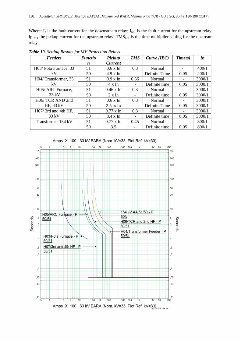
Table 10. Setting Results for MV Protection Relays
Feeders Functio
n
Pickup
Current
TMS Curve (IEC) Time(s) In
H03/ Pota Furnace, 33
kV
51 0.6 x In 0.3 Normal - 400/1
50 4.9 x In - Definite Time 0.05 400/1
H04/ Transformer, 33
kV
51 0.9 x In 0.36 Normal - 3000/1
50 4 x In - Definite time 0.05 3000/1
H05/ ARC Furnace,
33 kV
51 0.46 x In 0.3 Normal - 3000/1
50 2 x In - Definite time 0.05 3000/1
H06/ TCR AND 2nd
HF, 33 kV
51 0.6 x In 0.3 Normal - 3000/1
50 2.5 x In Definite Time 0.05 3000/1
H07/ 3rd and 4th HF,
33 kV
51 0.77 x In 0.3 Normal - 3000/1
50 3.4 x In - Definite time 0.05 3000/1
Transformer 154 kV 51 0.77 x In 0.45 Normal - 800/1
50 3.5 - Definite time 0.05 800/1

192 Abdulfetah SHOBOLE, Mustafa BAYSAL, Mohammed WADI, Mehmet Rida TUR / GU J Sci, 30(4): 180-198 (2017)
Figure 5. SKS Relays Coordination Curve
In the SKS when the maximum fault current occurs at the load terminal, the MV feeders’ relays which are
nearer to the source than the load feeders’ relays have to give 0.5-second gap to ensure the load feeders’
relay to operate. By following the above procedures (equations 6-8), this corresponds to TMS of 0.3. The
pickup currents are chosen as 1.1 times the maximum load currents. By using equations (6) to (8) the time
multiplier settings for all the relays are determined and summarized in Table 8. In Table 8, the pickup
settings are normalized with a ratio of current transformer primary currents. The coordination curve is
shown in Figure 5. The curve shows the proper coordination between the relays, for example, the
upstream relays (154 kV transformer feeder protection) operates only after the MV feeder protection fails
to operate for the fault happening on MV side. In addition to the time inverse, short circuit protection is
realized by definite time function. The current setting is determined so that it is below the minimum short
circuit current and above the load current. The pickup settings and time delay settings are shown in Table
8.
6. EARTH FAULT PROTECTION
Earth fault is the most frequent one of all faults. Its protection is provided by the relay which has a
response to the residual current. The load current must not affect the relay that is used for the EFP. Earth
contact resistance or neutral earthing impedance can limit the earth fault current. Consequently, to take
into consideration this low-level current, the earth fault relay is set to the minimum earth fault current or
20-40% of full-load current flowing through the system being protected [15-17]. Furthermore, similar to
the directional OCP, directional earth fault overcurrent can be applied in the following situations [17, 18]:
when the OCP is done by directional relays,
in insulated-earth networks or in Petersen coil earthed networks,
when the sensitivity of EFP is insufficient.
6.1 Influence of Earthing Nature on the Earth Fault Protection
The nature of zero sequence currents which are produced during earth fault is influenced by the method of
earthing. Thus, zero sequence currents and voltages which are utilized for the earth fault detection depend
on the system connections to the earth and the potential difference between the earthing points resulting
in a current flow in the earth paths. In the following sections, the effect of earthing types on the EFP and
the techniques to be used for detecting earth fault will be discussed.
6.1.1 Earth Fault Protection on Insulated Networks
In the insulated network, there is no earth fault current pass, so the whole system may remain operational
under earth fault condition. The system has to be designed to withstand the high steady-state and transient
overvoltage. The disadvantage of such network is the difficulty of detecting earth fault current. In modern
relays, the following methods are available.
6.1.1.1 Residual Voltage Method
The un-faulted phase voltages magnitude increases by a factor of √3 and their sum is no longer zero
during the occurrence of single phase to earth fault. Consequently, the earth fault can be detected by the
residual voltage element. The advantage of this method is that CTs are not used and only the voltage is
being measured. However, the unbalanced voltage happens on the whole affected system and it is difficult
to provide any discrimination.

193 Abdulfetah SHOBOLE, Mustafa BAYSAL, Mohammed WADI, Mehmet Rida TUR / GU J Sci, 30(4): 180-198 (2017)
6.1.1.2 Sensitive Earth Fault Method
This method is based on detection of imbalance charging currents per phase and mostly used in MV
networks. According to this mechanism, the relays on the healthy feeders detects the unbalance in
charging currents for their own feeders. In contrast, the relay in the faulted feeder detects the charging
currents in the rest of the system, with the current of its’ own feeders, canceled out (IH1+IH2 for feeder-3
of Figure 5).
In the insulated network due to the capacitive effect, the unbalance current on the un-faulted feeders leads
the residual voltage by 90º.
Due to the fault, the phase to earth voltage and consequently the charging current of healthy phases
rise by √3 .The resulting residual current will be three times the steady-state charging current per
phase.
Using the advantage of opposite current flow direction between the residual currents on the un-
faulted and faulted feeders, discrimination can be provided by using directional earth fault relay.
To make the residual current seen by the relay lie within the operating zone, the residual voltage
which is used as the polarizing quantity is shifted by 90o as shown in Figure 6.
(a)

194 Abdulfetah SHOBOLE, Mustafa BAYSAL, Mohammed WADI, Mehmet Rida TUR / GU J Sci, 30(4): 180-198 (2017)
(b)
Figure 6. (a). Phasor diagram for insulated system with phase (b) C-earth fault [6]
6.3.2 Earth Fault Protection on Petersen Coil Earthed Networks
In the Petersen coil earthed systems, reactance which is equal to the system capacitance to ground is used
to earth the system (Figure 7). Under steady state conditions, similar to the insulated system, no earth
fault current results when a single phase to earth fault occurs.
By using Figure 7 the following equations can be derived.
If = −IB − IC +Van
jXL 0 = −IB − IC +
Van
jXL
Van
jXL= IB + IC (8)
IL = IH1 + IH2 + IH3 + IF IR3 = IH3 + IF IR3 = IL − IH1 − IH2 (9)
IL=Van/jXL
jXL
-jXc
If=-IB-IC+Van/jXL=0
If Van/jXL=IB+IC
-jXc
-IB
-IC
Peterson Coil
If
-Vac/jXC=-IC
-Vab/jXC=-IB
-jXc
Source
IL
B
A
N
-IB
-IC
VabVac
Current Vector for A Phase Fault
Figure 7. Earth fault in Petersen Coil Earthed System [6]
195 Abdulfetah SHOBOLE, Mustafa BAYSAL, Mohammed WADI, Mehmet Rida TUR / GU J Sci, 30(4): 180-198 (2017)
By using equation (9) and Figure 8. Considering Figure 8, the magnitude of the residual current IR1 equals
to three times the steady-state charging current per phase. In contrast, the residual current on the faulted
feeder is equal to IL - IH1 - IH2. For the residual voltage (Vres) polarization, the residual current phase is
shifted by an angle less than 90o on the faulted feeder and greater than 90
o on the healthy feeders due to
the presence of resistance effect.
If directional relay with RCA of 0o is used, the faulted feeder through falls in the ‘operate’ area while the
residual current healthy feeder falls in the ‘restrain’ area of the relay characteristic. Therefore, in order to
increase the angular difference between the residual signals and to ensure a measurable earth fault
current, a resistance can be inserted in parallel with the Petersen Coil. It was already mentioned that the
method of system earthing also affects the Relay Characteristic Angle (RCA). In the practical
applications, there are varieties of grounding systems. The corresponding the RCA values to be used for
such systems are listed as follows:
0o RCA can be used for the resistance-earthed system,
-45o RCA can be used for the solidly-earthed distribution system and
-60o RCA can be used for the solidly-earthed transmission system.
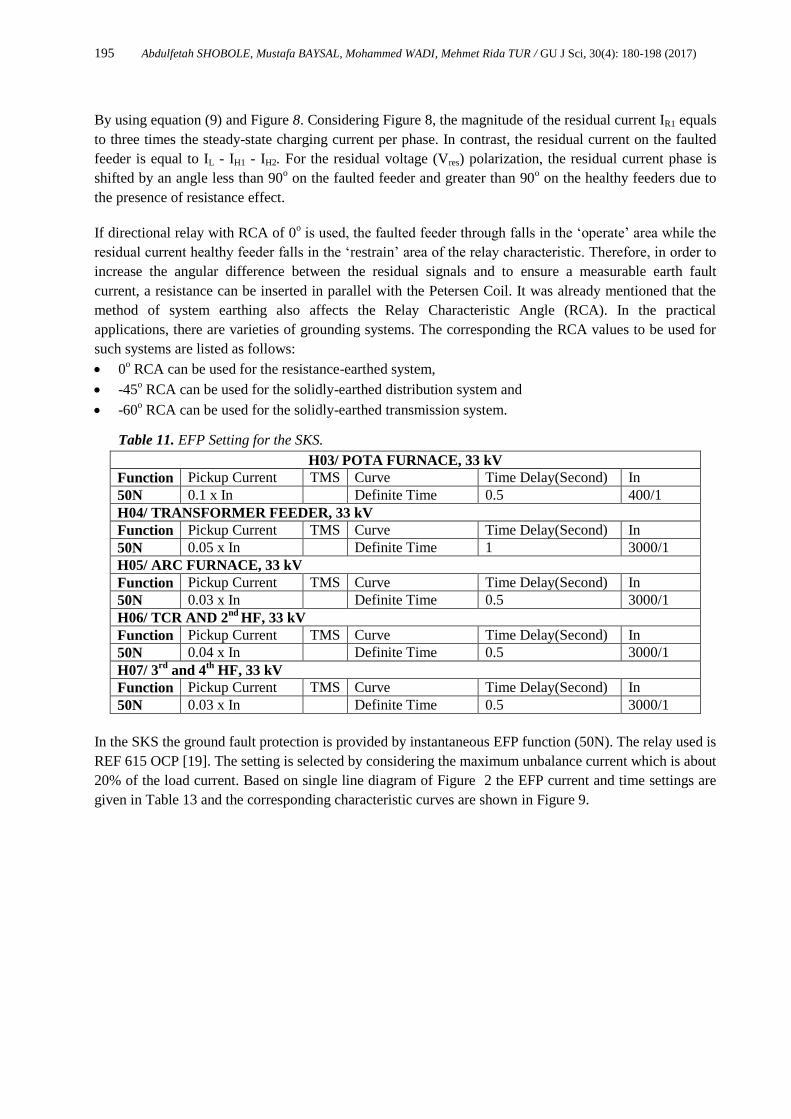
Table 11. EFP Setting for the SKS.
H03/ POTA FURNACE, 33 kV
Function Pickup Current TMS Curve Time Delay(Second) In
50N 0.1 x In Definite Time 0.5 400/1
H04/ TRANSFORMER FEEDER, 33 kV
Function Pickup Current TMS Curve Time Delay(Second) In
50N 0.05 x In Definite Time 1 3000/1
H05/ ARC FURNACE, 33 kV
Function Pickup Current TMS Curve Time Delay(Second) In
50N 0.03 x In Definite Time 0.5 3000/1
H06/ TCR AND 2nd
HF, 33 kV
Function Pickup Current TMS Curve Time Delay(Second) In
50N 0.04 x In Definite Time 0.5 3000/1
H07/ 3rd
and 4th
HF, 33 kV
Function Pickup Current TMS Curve Time Delay(Second) In
50N 0.03 x In Definite Time 0.5 3000/1
In the SKS the ground fault protection is provided by instantaneous EFP function (50N). The relay used is
REF 615 OCP [19]. The setting is selected by considering the maximum unbalance current which is about
20% of the load current. Based on single line diagram of Figure 2 the EFP current and time settings are
given in Table 13 and the corresponding characteristic curves are shown in Figure 9.

196 Abdulfetah SHOBOLE, Mustafa BAYSAL, Mohammed WADI, Mehmet Rida TUR / GU J Sci, 30(4): 180-198 (2017)
Figure 8. Distribution of currents during a C-phase-earth fault on radial distribution system [6]
Figure 9. Ground Fault ProC Curve
Ia1
Ib1
IR1
Ia2
Ib2
Ia3
Ib3
IC3=IF
IL
jXL
IR2
IR3
-jXc1
-jXc2
-jXc3
IH1
IH2
IH3IH1+IH2
IF
IL
IL=IF+IH1+IH2-IH3

197 Abdulfetah SHOBOLE, Mustafa BAYSAL, Mohammed WADI, Mehmet Rida TUR / GU J Sci, 30(4): 180-198 (2017)
7. CONCLUSION
The electrical power system is expensive investments which have to be designed, implemented and
operated with great care so that it provides valuable results. ESS is one of the components of such
investment which requires detailed engineering work from its design phase to the implementation phase.
If proper protection system design procedure is not followed, the fault currents that may result from
abnormal conditions can damage the components of this expensive investment within a fraction of
minutes. Thus, during substation design stage, detailed analysis of the system, like a short circuit and load
analysis has to be made. Based on the analysis results, protection systems, equipment and techniques have
to be properly determined before the implementation stage. This involves the selection of appropriate
circuit breakers, fuses, isolators, instrument transformers, protection relays, etc. Moreover, proper
coordination among these equipments is a crucial task which has to be handled by protection engineer. In
this paper, the proper steps for designing protection system is discussed with a practical case study of
SKS project. The engineering steps start from load analysis and short circuit study, which is discussed in
this study. The selection of appropriate instrument transformers is also among the fundamental steps for
proper operation of the protection system. Based on the requirement of the system to be protected, over-
current, differential and distance protection schemes are implemented in the study. However, the distance
and differential protection will be covered in the part-2 of this paperwork. Overcurrent and EFP are the
earliest protection to be used for the protection of power systems. The engineering issues related to
overcurrent and EFP are discussed in detail. In addition, this protection system is designed and
implemented for the SKS by providing the necessary coordination among the protection relays.
Generally, this paper discussed the necessary engineering steps to be followed for the currently used
protection schemes for the modern IEDs. The results from the coordination study are implemented to the
substation protection relays. After the necessary test and commissioning of the protection system, SKS is
successfully energized.
REFERENCES
[1] M. Wadi, M. Baysal and A. Shobole “Comparison between Open-Ring and Closed-Ring Grids
Reliability”, 4th International Conference on Electrical and Electronics Engineering, Ankara,
Turkey, (2017).
[2] Electric Power Engineering Handbook, Electrical Power Substation Engineering, edited by John D.
McDonald, 2nd edition, Taylor & Francis Group, LLC, (2007).
[3] Switch Gear and Substations, Siemens Energy Sector, Power Engineering Guide, Edition 7.
[4] Raj Nagarsheth, Sushant Singh, Study of gas insulated substation and its comparison with air
insulated substation, International Journal of Electrical Power and Energy Systems, pp 481–485,
(2014).
[5] IEEE Power Engineering Society, IEEE Guide for Recommended Electrical Clearances and
Insulation Levels in Air-Insulated Electrical Power Substations, IEEE-SA Standards Board, and
Approved 6 December 2006 accessed online on
http://ieeexplore.ieee.org/stamp/stamp.jsp?tp=&arnumber=4201973, (2006).
[6] Network Protection and Automation Guide, Protective Relays Measurement and Control, ISBN:
978-0-9568678-0-3 Published by Alstom Grid, (2011).
[7] C.R. Bayliss, B.J. Hardy, Transmission and Distribution Electrical Engineering Fourth Edition, pp
93–119, (2012).

198 Abdulfetah SHOBOLE, Mustafa BAYSAL, Mohammed WADI, Mehmet Rida TUR / GU J Sci, 30(4): 180-198 (2017)
[8] Carlos A. Castillo Salazar, Arturo Conde Enríquez, Satu Elisa Schaeffer, Directional overcurrent
relay coordination considering non-standardized time, Electric Power Systems Research, Volume
122, pp 42-49, (2015).
[9] Dr C.R. Bayliss, CEng FIET, B.J. Hardy, CEng FIET, Transmission and Distribution Electrical
Engineering, Fourth Edition, Chapter 10 – Relay Protection pp 287–359, (2012).
[10] C.R. Bayliss, B.J. Hardy, Current and Voltage Transformers, Transmission and Distribution
Electrical Engineering, Fourth Edition, pp 157-170, (2012)
[11] A.H.A. Bakar, BanJuan Ooi, P. Govindasamyb, ChiaKwang Tana, H.A. Illiasc, H. Mokhlisc,
Directional overcurrent and earth-fault protections for a biomass microgrid system in Malaysia,
International Journal of Electrical Power & Energy Systems Volume 55, pp 581–591, (2014).
[12] A.H.A. Bakar, H. Mokhlis, H.A. Illias, P.L. Chong, The study of directional overcurrent relay and
directional earth-fault protection application for 33 kV underground cable system in Malaysia,
International Journal of Electrical Power & Energy Systems Volume 40, Issue 1, pp 113–119,
(2012).
[13] S.A. Ahmadia, H. Karamib, M.J. Sanjarib, H. Tarimoradib, G.B. Gharehpetianb, Application of
hyper-spherical search algorithm for optimal coordination of overcurrent relays considering
different relay characteristics, International Journal of Electrical Power & Energy Systems, Volume
83, pp 443–449, (2016).
[14] http://www.teias.gov.tr/Eng/.
[15] M. Wadi, M. R. Tur and M. Tanriöven “Optimization of Distributed Generation Using Homer
Software and Fuzzy Logic Control”, 3rd European Conference on Renewable Energy Systems,
Antalya, Turkey, 7-10 Oct., (2015).
[16] A. Shobole, M. Baysal, M. Wadi and M. R. Tur “Effects of Distributed Generations’ Integration to
the Distribution Networks Case Study of Solar Power Plant”, International Journal of Renewable
Energy Research, Vol. 7, Issue 2, pp 954-964, (2017).
[17] Li-Hsiung Chen, OCP for distribution feeders with renewable generation, International Journal of
Electrical Power & Energy Systems Volume 84, pp 202–213, (2017).
[18] Thanga Raj Chelliaha, Radha Thangaraja, Srikanth Allamsettya, Millie Pantb, Coordination of
directional overcurrent relays using opposition based chaotic differential evolution algorithm,
International Journal of Electrical Power & Energy Systems, Volume 55, pp 341–350, (2014)
[19] Relion Protection and Control 615 series Technical Manual, Document ID: 1MRS756887 Issued:
2010-09-24 Revision: E Product version: 3.0, ABB, (2010).