journal of science thermodynamic analysis of industrial
TRANSCRIPT

*Corresponding author, e-mail: [email protected]
Research Article GU J Sci 34(4): 1145-1161 (2021) DOI: 10.35378/gujs.788864
Gazi University
Journal of Science
http://dergipark.gov.tr/gujs
Thermodynamic Analysis of Industrial Cooling Systems with the Usage of
Different Types of Evaporators: Experimental Study
Suleyman ERTEN1 , Meltem KOSAN2,* , Furkan ISGEN1 , Esra DEMIRCI1 , Mustafa AKTAS3
1Nurdil Technical Cooling, 06500, Ankara, Turkey 2Kahramanmaras Istiklal University, 46100, Kahramanmaras, Turkey 3Gazi University, Department of Energy Systems Engineering, 06500, Ankara, Turkey
Highlights
• 1/2" smooth tube and 3/8" grooved tube types evaporators are designed for industrial refrigerators.
• Theoretical and experimental analysis and comparison of smooth and grooved tube evaporators.
• The system COP value is 2.807, while it is calculated as 3.013 for the second system.
• The grooved tube evaporator has better cooling performance compared to the smooth tube evaporator.
Article Info
Abstract
Energy efficiency and the amount of refrigerant in heat exchangers used in cooling systems has
recently been an important research subject. In this study, in order to compare and analyze
different types of evaporators, industrial refrigerators were designed and in this context, test
setups in accordance with TS EN ISO 23953-2 standard were produced. R290 (propane) was used
as the refrigerant in the designed system. During the experiment, temperature-pressure
measurements were taken at a certain point in the cooling system equipment of the products,
which were cooled every minute, and test data were recorded. As a result of the data obtained
from the experimental results, while the temperature difference of the air entering and leaving the
evaporators was 6.797 ℃ in the first system using ½” tube diameter evaporator, it was calculated
as 7.052 ℃ in the corrugated and hydrophilic coated second system using 3/8” tube diameter. In
the experimental setups, the energy consumed in the first and second systems and the masses of
R-290 refrigerant were measured as 24.64 kWh, 23.39 kWh and 700 grams, 430 grams,
respectively. Consequently, it was calculated that the second system was 5.073% and 38.57%
more efficient in terms of energy efficiency and the refrigerant mass used. Coefficient of
performance values for the first and second systems were found as 2.807 and 3.013, respectively.
Received:01 Sep 2020 Accepted:09 Jan 2021
Keywords
Cooling Evaporator
Energy efficiency
Hydrophilic coating
1. INTRODUCTION
At present, it is known that aluminum fins are used in heat exchangers, which are frequently used for
industrial cooling systems. Bacteria and fungi can survive on the surface of aluminum fins and cause
contamination of the air to be conditioned. Therefore, hydrophilic, anticorrosive and antibacterial coatings
have been developed for aluminum fins [1]. In addition to its anti-corrosive effect, the hydrophilic coating
increases the wettability of the applied surface by reducing its hydrophobic property. If the evaporator
surface has a hydrophobic structure, the moisture in the environment will condense as drops on the fins.
Instead of spreading to the surface, the water molecules on the surface in the form of drops will create
resistance against the air passing through the fins of the evaporator, causing an increase in pressure between
the evaporator inlet and outlet, while adversely affecting the heat transfer. Min et al. investigated the
surface wettability of the hydrophilic coated evaporator and the pressure change in the long-term operating
conditions of the evaporator, and it was determined that the hydrophilic coated surface reduced the pressure
drop by 34% [2]. Shen et al. applied different concentrations to improve the hydrophilic coating applied to
the copper fin evaporators. They investigated the increase in evaporator capacity for 20%, 50% and 80%
relative humidity conditions, respectively, and observed that the capacity increased by 1.3%, 2.5% and 5%
1146 Meltem KOSAN et al. / GU J Sci, 34(4): 1145-1161 (2021)
[3]. Moallem et al. examined the freezing behavior of hydrophilic and hydrophobic coated microchannel
heat exchangers. They found that hydrophobic and hydrophilic coated heat exchangers freeze after 13
minutes and 20 minutes, respectively, and that the cooling performance of hydrophilic coated microchannel
heat exchangers is 4.5% better [4].
In addition to the geometry of the evaporators, the fins used, the material produced and the applied coatings,
one of the parameters that change the cooling capacity is to accelerate the evaporation of the standard
liquids and refrigerants passing through the evaporator tubes. Developing technology has led to the
enhancement of in-tube evaporation used in many air conditioning and cooling systems. Considering the
improvement of the total heat transfer of the evaporator, it is necessary to consider the external heat transfer
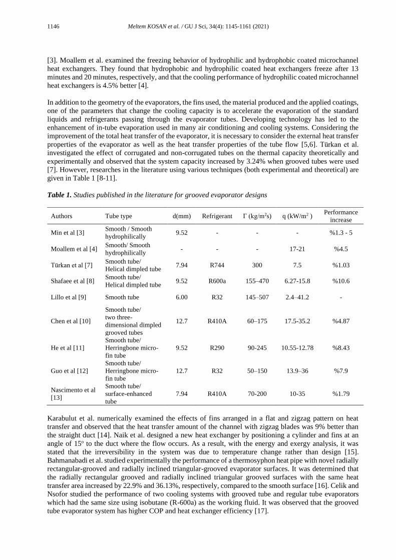
properties of the evaporator as well as the heat transfer properties of the tube flow [5,6]. Türkan et al.
investigated the effect of corrugated and non-corrugated tubes on the thermal capacity theoretically and
experimentally and observed that the system capacity increased by 3.24% when grooved tubes were used
[7]. However, researches in the literature using various techniques (both experimental and theoretical) are
given in Table 1 [8-11].
Table 1. Studies published in the literature for grooved evaporator designs
Authors Tube type d(mm) Refrigerant Γ (kg/m2s) q (kW/m2 ) Performance
increase
Min et al [3] Smooth / Smooth
hydrophilically 9.52 - - - %1.3 - 5
Moallem et al [4] Smooth/ Smooth
hydrophilically - - - 17-21 %4.5
Türkan et al [7] Smooth tube/
Helical dimpled tube 7.94 R744 300 7.5 %1.03
Shafaee et al [8] Smooth tube/
Helical dimpled tube 9.52 R600a 155–470 6.27-15.8 %10.6
Lillo et al [9] Smooth tube 6.00 R32 145–507 2.4–41.2 -
Chen et al [10]
Smooth tube/
two three-
dimensional dimpled
grooved tubes
12.7 R410A 60–175 17.5-35.2 %4.87
He et al [11]
Smooth tube/
Herringbone micro-
fin tube
9.52 R290 90-245 10.55-12.78 %8.43
Guo et al [12]
Smooth tube/
Herringbone micro-
fin tube
12.7 R32 50–150 13.9–36 %7.9
Nascimento et al
[13]
Smooth tube/
surface-enhanced
tube
7.94 R410A 70-200 10-35 %1.79
Karabulut et al. numerically examined the effects of fins arranged in a flat and zigzag pattern on heat
transfer and observed that the heat transfer amount of the channel with zigzag blades was 9% better than
the straight duct [14]. Naik et al. designed a new heat exchanger by positioning a cylinder and fins at an
angle of 15o to the duct where the flow occurs. As a result, with the energy and exergy analysis, it was
stated that the irreversibility in the system was due to temperature change rather than design [15].
Bahmanabadi et al. studied experimentally the performance of a thermosyphon heat pipe with novel radially
rectangular-grooved and radially inclined triangular-grooved evaporator surfaces. It was determined that
the radially rectangular grooved and radially inclined triangular grooved surfaces with the same heat
transfer area increased by 22.9% and 36.13%, respectively, compared to the smooth surface [16]. Celik and
Nsofor studied the performance of two cooling systems with grooved tube and regular tube evaporators
which had the same size using isobutane (R-600a) as the working fluid. It was observed that the grooved
tube evaporator system has higher COP and heat exchanger efficiency [17].

1147 Meltem KOSAN et al. / GU J Sci, 34(4): 1145-1161 (2021)
In this study, the effects of finned tube evaporator and hydrophilic coating, which are among the evaporator
types used in cooling and heating applications, on system performance were analyzed. The aim of the study
is to investigate theoretically and experimentally the effect of grooved and hydrophilic coated evaporators
on vertical type open positive industrial refrigerators. In this context, a cooling test mechanism was installed
and the changing temperature, pressure and power values were recorded instantly and presented in graphs,
and recommendations were made to improve the cooling system economically and technically by
determining their effects on the system performance.
2. MATERIAL METHOD
In this study, it is aimed to compare and analyze different types of evaporators in an industrial refrigeration
system. M1 type vertical, open, vapor compression industrial refrigeration system operating with R290
(Propane) refrigerant was designed, manufactured and tested by calculating the cooling load. Tests were
carried out in the test room under Class-3 25 ℃ temperature and 60% relative humidity conditions. In
addition, the tests were conducted equally and in accordance with the ISO 23953-2 standard, using
equipments with the same properties in both types of evaporators. At this point, from the evaporators whose
properties are given in Table 2, 1/2 "diameter straight tube evaporator and 3/8" diameter corrugated tube,
hydrophilic coated evaporator were connected to the test setup and the experimental data were recorded.
Table 2. Technical and geometrical characteristics of evaporators tested in experimental setup
1/2" smooth tube 3/8" grooved tube
Type of Tube Smooth tube Grooved Tube Unit
Geometry-Diameter 40x35-1/2" 35x35-3/8" inc
Number of Tube 32 40 -
Heat Exchanger Surface 22.1 26.1 m2
Tube outer diameter (do) 12.700 9.52 mm
Tube inner diameter (di) 11.360 8.82 mm
Tube grooved diameter (dt) - 8.46 mm
Grooved heıght (f) - 0.2 mm
Grooved apex angle (θ) - 53o degree
Grooved angle (β) - 20o degree
Number of grooved (n) - 65 -
Coated Aluminium - hydrophilically (0.02 mm) mm
Refrigerant liquid R290 (propane) R290 (propane) -
Refrigerant quantities 700 430 (g)
Environmental temperature 24.77 24.51 ℃
In the produced experimental setup, two condensers and compressors are operated together with an
evaporator with two inlets and outlets. Two pressure zones were created in the system using capillary tubes.
Experimental set up and its measurement points are given in Figure 1.

1148 Meltem KOSAN et al. / GU J Sci, 34(4): 1145-1161 (2021)
Figure 1. Cooling system and measuring points
The experiments were carried out in the test room with calibrated test devices within the scope of TS EN
ISO 23953-2 standard. Cooling performance of the system, energy consumption, temperature
measurements, pressure measurements and energy efficiency tests were performed. While performing these
tests, temperature measurements were taken every minute by means of thermocouples from certain points
of cooling systems equipment (compressor, condenser and evaporator inlet-outlet temperature values).
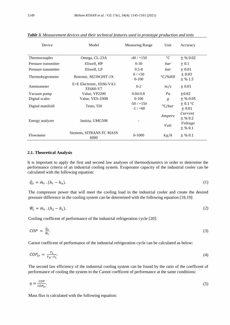
Information for measurement equipments used in prototype production and tests is given in Table 3.
1149 Meltem KOSAN et al. / GU J Sci, 34(4): 1145-1161 (2021)
Table 3. Measurement devices and their technical features used in prototype production and tests
Device
Model Measuring Range Unit Accuracy
Thermocouples Omega, CL-23A -40 / +150 °𝐶 ± % 0.02
Pressure transmitter Eliwell, HP 0-30 𝑏𝑎𝑟 ± 0.1
Pressure transmitter Eliwell, LP 0.5-8 𝑏𝑎𝑟 ± 0.01
Thermohygrometer Rotronic, M23W2HT-1X 0 / +50
0-100 °𝐶/%𝑅𝐻
± 0.03
± % 1.5
Anemometer E+E Electronic, EE66-VA3
EE660-V7 0-2 𝑚/𝑠 ± 0.01
Vacuum pump Value, VP2200 0.04-0.8 𝑃𝑎 ±0.02
Digital scales Value, VES-100B 0-100 𝑔 ± % 0.05
Digital manifold Testo, 550 -50 / +150
-1 / +60 ℃/𝑏𝑎𝑟
± 0.1 °𝐶
± 0.01
Energy analyzer Janitza, UMG508 -
𝐴𝑚𝑝𝑒𝑟𝑒
𝑉𝑜𝑙𝑡
𝐶𝑢𝑟𝑟𝑒𝑛𝑡
± % 0.2
𝑉𝑜𝑙𝑡𝑎𝑔𝑒
± % 0.1
Flowmeter Siemens, SITRANS FC MASS
6000 0-1000 𝑘𝑔/ℎ ± % 0.1
2.1. Theoretical Analysis
It is important to apply the first and second law analyses of thermodynamics in order to determine the
performance criteria of an industrial cooling system. Evaporator capacity of the industrial cooler can be
calculated with the following equation:
�̇�𝑒 = �̇�𝑟 . (ℎ1 − ℎ4). (1)
The compressor power that will meet the cooling load in the industrial cooler and create the desired
pressure difference in the cooling system can be determined with the following equation [18,19]:
�̇�𝑐 = �̇�𝑟 . (ℎ2 − ℎ1). (2)
Cooling coefficent of performance of the industrial refrigeration cycle [20]:
𝐶𝑂𝑃 = �̇�𝑒
�̇�𝑐. (3)
Carnot coefficent of performance of the industrial refrigeration cycle can be calculated as below:
𝐶𝑂𝑃𝑡𝑟 = 𝑇𝐿
𝑇𝐻−𝑇𝐿. (4)
The second law efficiency of the industrial cooling system can be found by the ratio of the coefficent of
performance of cooling the system to the Carnot coefficent of performance at the same conditions:
𝜂 =𝐶𝑂𝑃
𝐶𝑂𝑃𝑡𝑟. (5)
Mass flux is calculated with the following equation:
1150 Meltem KOSAN et al. / GU J Sci, 34(4): 1145-1161 (2021)
Γ =�̇�𝑟
𝐴𝑐. (6)
Using the experimental data, the heat transfer coefficient resulting from the difference between the
temperature of the refrigerant inside the evaporator (𝑇𝑒,𝑟) and the air temperature outside the evaporator
(𝑇𝑎) can be determined using the following equation [21]:
ℎ𝑒𝑥𝑝 =�̇�𝑒
𝐴s.(𝑇𝑎−𝑇𝑒,𝑟). (7)
Bond number, which is used to describe the contribution of the liquid-gas interface to heat transfer, which
will be formed by the evaporation of the R290 refrigerant in the evaporator, is known as the ratio of
gravitational forces to surface tension forces and can be calculated with the following equation [22]:
𝐵𝑜 =𝑔.𝜋.𝜌𝑙.𝑓.𝑑𝑡
8.𝑛.𝜎. (8)
The Froude number is used to define the flow characteristic due to the dual phase flow formed in the
evaporator and can be calculated with the following equation:
𝐹𝑟 =Г2
𝑔.𝜌𝑣2.𝑑𝑡
. (9)
In order to determine the flow type in the case of two-phase flow in pipes containing grooved, the proposed
Reynolds number is given with the following equation [23]:
𝑅𝑒𝑥 =
2.f.n.(1−sin (𝜃2⁄ )
𝜋.𝑑𝑡.cos (𝜃2⁄ )
+1
cos (𝛽).
(10)
The two-phase flow that occurs in the evaporator makes it difficult to resolve heat transfer. One of these
difficulties is determining the evaporation heat transfer coefficient. Zhang et al. Presented the following
equation to find the heat transfer coefficient in two-phase flow developed for azeotropic refrigerants [24,
25]:
𝑁𝑢𝑐𝑣 = (0.023. (Г. 𝑑𝑡
𝜇𝑙)
0.8
. 𝑃𝑟𝑙1/3) . ((1 − x) + 2.63. x. (
𝜌𝑙
𝜌𝑣)
1/2
)
0.8
, (11)
ℎ𝑐𝑣 = (𝑘𝑙
𝑑𝑡) . 𝑁𝑢𝑐𝑣 . 𝑅𝑒𝑥
2.14. (𝐵𝑜. 𝐹𝑟)−0.15. (𝑑𝑜
𝑑𝑡)
0.59
. (100
Г)
0.36
, (12)
ℎ𝑛𝑏 = 55. Pr0.12. (−logPr)−0.55. M−0.5. q2/3. 𝐴𝑐 . 𝑋𝑡𝑡0.36. (
𝑑𝑜
𝑑𝑡)
0.38
, (13)
𝑋𝑡𝑡 = (1 − x
x)
0.9
. (𝜌𝑣
𝜌𝑙)
0.5
. (𝜇𝑙
𝜇𝑣)
0.1
, (14)
ℎ𝑡𝑝 = ℎ𝑛𝑏 + ℎ𝑐𝑣 . (15)
With the developing technology and industry day by day, CO2 emissions are increasing. Heat pumps used
in cooling and heating applications are known to produce much lower CO2 emissions than other fossil
fuels. With the improvement refrigerant technology, the use of natural refrigerants in cooling systems
1151 Meltem KOSAN et al. / GU J Sci, 34(4): 1145-1161 (2021)
enables heat pumps to be much more environmentally friendly. Using the equation below, it can be
calculated how many kilograms of CO2 emitted annually for the preferred refrigerant [26]:
𝐶𝑂2𝑒 = (𝑇𝑅410 ∗ 10−3) ∗ 𝑡𝑦𝑒𝑎𝑟 ∗ (𝐺𝑊𝑃𝐶𝑂2410𝑎⁄
∗ (0.5 ∗ (𝑅32 + 𝑅125))). (16)
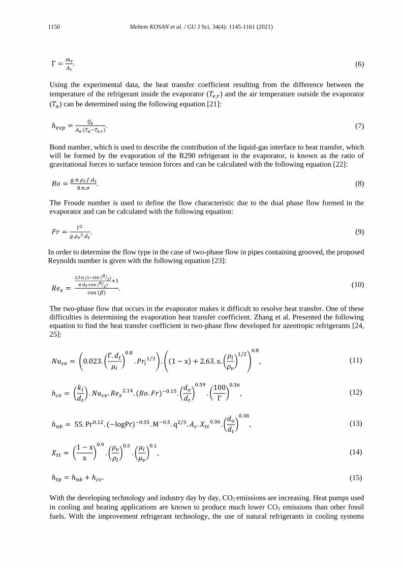
3. RESULTS AND DISCUSSIONS
The experimental set-up designed, produced and analyzed within the scope of ISO 23953-2 standard is
shown in Figure 1. In this study, two alternatives for evaporators used in refrigeration cycles were examined
theoretically and experimentally. First system a 1/2 "pipe diameter smooth tube and hydrophilic uncoated
evaporator was used, in the second system a 3/8" diameter grooved tube and hydrophilic coated lamellar
evaporator was used. Thermodynamic properties of the refrigerant used in evaporator theoretical and
experimental values are given in Table 4.
Table 4. Thermodynamic properties of refrigerant used in theoretical and experimental values
Smooth tube evaporator Grooved tube evaporator
Г (kg/m2s) 294.375 177.452
X tt N/A 0.299
Prl 23.085 23.085
Bo 2.94E-03 2.94E-03
Fr 7345.670 7345.670
Nucv 585.633 585.633
X 0.35 0.334
M (kg/kmol) 0.0441 0.0441
μv 5.61E-06 5.61E-06
μl 0.000148431 0.000148431
kl(W/mK) 0.0153 0.0153
ρv (kg/m3) 7.187 7.187
ρL(kg/m3) 535.026 535.026
σ (N/m) 2.14E-02 2.14E-02
Pr (pressure / critical pressure) N/A 0.081
It is known that by increasing the effect of frictional forces on hydrophilic coated lamellae, water droplets
do not remain in a spherical form on the surface, but tend to spread on the surface. Due to this effect of
water drops, the surface areas in contact with the blades will increase and faster evaporation and slow ice
formation will be observed. Thus, the water resistance on the coverslips is weakened and the thermal
resistance caused by the water decreases and accordingly an increase in heat transfer is expected. Gibbons
et al. (2020) examined the water droplet on the hydrophilic coated surface and the heat and mass transfer
of the water droplet showing superhydrophobic properties and found that the evaporation rate of the water
droplet on the hydrophilic coated surface was 34% faster [27].
The total energy consumption and charged R-290 refrigerant mass in the first and second systems in the
experimental setup were measured as 24.64 kWh, 23.39 kWh and 700 grams, 430 grams, respectively. As
a result of these data, it is calculated that the second system is 5.073% and 38.57% more efficient in terms
of energy efficiency and refrigerant mass.
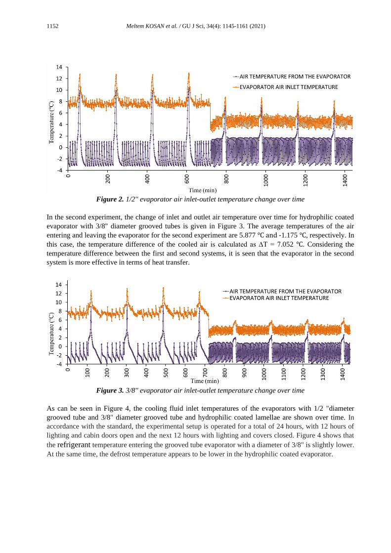
In the first experiment, the changing of the inlet and outlet air temperature during the experiment for the
evaporator with 1/2" tube diameter without groove and lamellar coating is given in Figure 2. Looking at
the air temperatures in Figure 2, the system performs defrosting every 3 hours. At the same time, the average
temperatures of the air entering and leaving the evaporator are seen as 6.327 ℃, and -0.407 ℃, respectively.
In this case, the temperature difference of the cooled air is calculated as ∆T = 6.797 ℃.
1152 Meltem KOSAN et al. / GU J Sci, 34(4): 1145-1161 (2021)
Figure 2. 1/2'' evaporator air inlet-outlet temperature change over time
In the second experiment, the change of inlet and outlet air temperature over time for hydrophilic coated
evaporator with 3/8" diameter grooved tubes is given in Figure 3. The average temperatures of the air
entering and leaving the evaporator for the second experiment are 5.877 ℃ and -1.175 ℃, respectively. In
this case, the temperature difference of the cooled air is calculated as ∆T = 7.052 ℃. Considering the
temperature difference between the first and second systems, it is seen that the evaporator in the second
system is more effective in terms of heat transfer.
Figure 3. 3/8'' evaporator air inlet-outlet temperature change over time
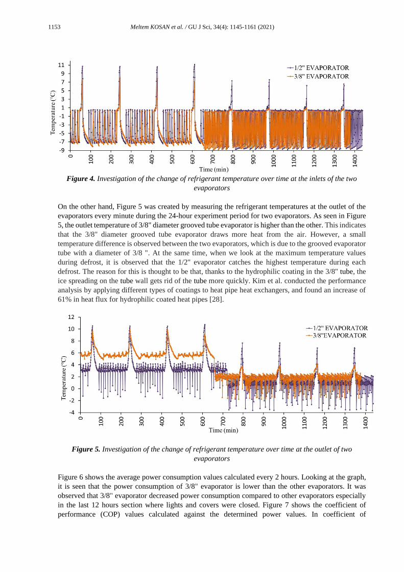
As can be seen in Figure 4, the cooling fluid inlet temperatures of the evaporators with 1/2 "diameter
grooved tube and 3/8" diameter grooved tube and hydrophilic coated lamellae are shown over time. In
accordance with the standard, the experimental setup is operated for a total of 24 hours, with 12 hours of
lighting and cabin doors open and the next 12 hours with lighting and covers closed. Figure 4 shows that
the refrigerant temperature entering the grooved tube evaporator with a diameter of 3/8" is slightly lower.
At the same time, the defrost temperature appears to be lower in the hydrophilic coated evaporator.
1153 Meltem KOSAN et al. / GU J Sci, 34(4): 1145-1161 (2021)
Figure 4. Investigation of the change of refrigerant temperature over time at the inlets of the two
evaporators
On the other hand, Figure 5 was created by measuring the refrigerant temperatures at the outlet of the
evaporators every minute during the 24-hour experiment period for two evaporators. As seen in Figure
5, the outlet temperature of 3/8" diameter grooved tube evaporator is higher than the other. This indicates
that the 3/8" diameter grooved tube evaporator draws more heat from the air. However, a small
temperature difference is observed between the two evaporators, which is due to the grooved evaporator
tube with a diameter of 3/8 ". At the same time, when we look at the maximum temperature values
during defrost, it is observed that the 1/2" evaporator catches the highest temperature during each
defrost. The reason for this is thought to be that, thanks to the hydrophilic coating in the 3/8" tube, the
ice spreading on the tube wall gets rid of the tube more quickly. Kim et al. conducted the performance
analysis by applying different types of coatings to heat pipe heat exchangers, and found an increase of
61% in heat flux for hydrophilic coated heat pipes [28].
Figure 5. Investigation of the change of refrigerant temperature over time at the outlet of two
evaporators
Figure 6 shows the average power consumption values calculated every 2 hours. Looking at the graph,
it is seen that the power consumption of 3/8" evaporator is lower than the other evaporators. It was
observed that 3/8" evaporator decreased power consumption compared to other evaporators especially
in the last 12 hours section where lights and covers were closed. Figure 7 shows the coefficient of
performance (COP) values calculated against the determined power values. In coefficient of

1154 Meltem KOSAN et al. / GU J Sci, 34(4): 1145-1161 (2021)
performance values, the average coefficient of performance value for 1/2" evaporator was 2.807, while
it was calculated as 3.013 for 3/8" evaporator.
Figure 6. Comparison of average power values calculated every 2 hours
Figure 7. Comparision of COP values calculated every 2 hours
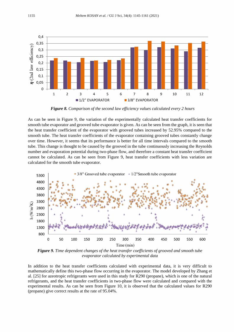
The second law efficiency of both evaporators is given in Figure 8. The second law efficiency values are
ranging from 20.551 – 32.012 % and 20.925 – 36.921 % for 1/2" and 3/8" evaporators, respectively. The
average second law efficiency values of 1/2" and 3/8" evaporators were determined as 26.126 % and
28.898 %, too. The highest exergy efficiencies were 32.012 % for 1/2" evaporator and 36.921 % for 3/8"
evaporator. Evaluating Figure 8, the second-law efficiency of 3/8" diameter grooved tube evaporator is
9.593 % higher than the other, meaning that it has a better thermodynamic perfection.
1155 Meltem KOSAN et al. / GU J Sci, 34(4): 1145-1161 (2021)
Figure 8. Comparison of the second law efficiency values calculated every 2 hours
As can be seen in Figure 9, the variation of the experimentally calculated heat transfer coefficients for
smooth tube evaporator and grooved tube evaporator is given. As can be seen from the graph, it is seen that
the heat transfer coefficient of the evaporator with grooved tubes increased by 52.95% compared to the
smooth tube. The heat transfer coefficients of the evaporator containing grooved tubes constantly change
over time. However, it seems that its performance is better for all time intervals compared to the smooth
tube. This change is thought to be caused by the grooved in the tube continuously increasing the Reynolds
number and evaporation potential during two-phase flow, and therefore a constant heat transfer coefficient
cannot be calculated. As can be seen from Figure 9, heat transfer coefficients with less variation are
calculated for the smooth tube evaporator.
Figure 9. Time dependent changes of the heat transfer coefficients of grooved and smooth tube
evaporator calculated by experimental data
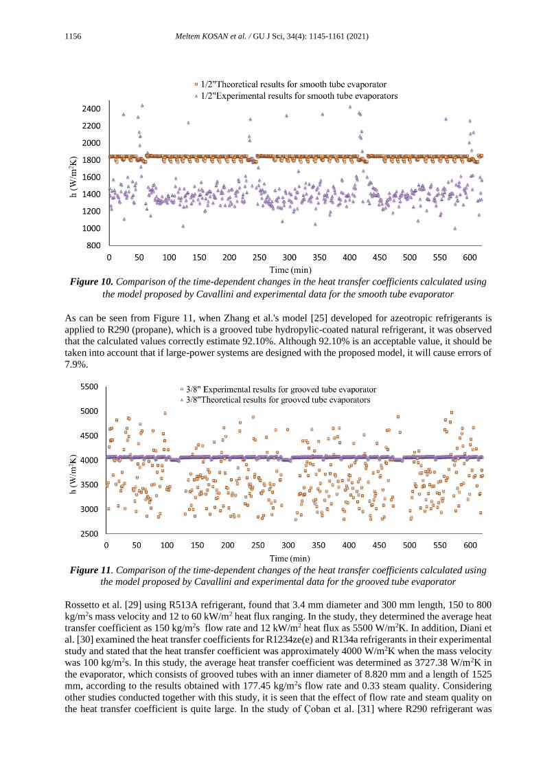
In addition to the heat transfer coefficients calculated with experimental data, it is very difficult to
mathematically define this two-phase flow occurring in the evaporator. The model developed by Zhang et
al. [25] for azeotropic refrigerants were used in this study for R290 (propane), which is one of the natural
refrigerants, and the heat transfer coefficients in two-phase flow were calculated and compared with the
experimental results. As can be seen from Figure 10, it is observed that the calculated values for R290
(propane) give correct results at the rate of 95.04%.
1156 Meltem KOSAN et al. / GU J Sci, 34(4): 1145-1161 (2021)
Figure 10. Comparison of the time-dependent changes in the heat transfer coefficients calculated using
the model proposed by Cavallini and experimental data for the smooth tube evaporator
As can be seen from Figure 11, when Zhang et al.'s model [25] developed for azeotropic refrigerants is
applied to R290 (propane), which is a grooved tube hydropylic-coated natural refrigerant, it was observed
that the calculated values correctly estimate 92.10%. Although 92.10% is an acceptable value, it should be
taken into account that if large-power systems are designed with the proposed model, it will cause errors of
7.9%.
Figure 11. Comparison of the time-dependent changes of the heat transfer coefficients calculated using
the model proposed by Cavallini and experimental data for the grooved tube evaporator
Rossetto et al. [29] using R513A refrigerant, found that 3.4 mm diameter and 300 mm length, 150 to 800
kg/m2s mass velocity and 12 to 60 kW/m2 heat flux ranging. In the study, they determined the average heat
transfer coefficient as 150 kg/m2s flow rate and 12 kW/m2 heat flux as 5500 W/m2K. In addition, Diani et
al. [30] examined the heat transfer coefficients for R1234ze(e) and R134a refrigerants in their experimental
study and stated that the heat transfer coefficient was approximately 4000 W/m2K when the mass velocity
was 100 kg/m2s. In this study, the average heat transfer coefficient was determined as 3727.38 W/m2K in
the evaporator, which consists of grooved tubes with an inner diameter of 8.820 mm and a length of 1525
mm, according to the results obtained with 177.45 kg/m2s flow rate and 0.33 steam quality. Considering
other studies conducted together with this study, it is seen that the effect of flow rate and steam quality on
the heat transfer coefficient is quite large. In the study of Çoban et al. [31] where R290 refrigerant was

1157 Meltem KOSAN et al. / GU J Sci, 34(4): 1145-1161 (2021)
used, it was determined that the heat transfer coefficient determined for 424 kg/m2s flow rate and 0.35
dryness degree was 5000 W/m2K. Apart from this, although it is seen that the models developed for two-
phase flow in the literature do not fully support the experimental results, it was seen that the mathematical
model developed by Zhang et al. used in this study correctly predicted the experimental results between
90% and 95%.
4. CONCLUSIONS
In this study, industrial coolers with different types of evaporators were designed, manufactured and tested.
Throughout the experiment, the following successful results were attained:
• In the experimental setups, the energy consumed in the first and second systems and the masses of
R-290 refrigerant were measured as 24.64 kWh, 23.39 kWh and 700 grams, 430 grams,
respectively. This shows that the second system is 5.073% and 38.57% more efficient in terms of
energy efficiency and the refrigerant used, respectively.
• During the experiments, the average temperature difference of the air entering and leaving the
evaporator was calculated as ∆T = 6.797 ℃ and ∆T = 7.052 ℃ for the first and second systems,
respectively. The hydrophilic coating used in the evaporator prevents the formation of resistance
to airflow between the evaporator fins by spreading water molecules on the evaporator surface.
When two systems are compared in terms of performance, the first system COP value is 2.807,
while it is calculated as 3.013 for the second system.
• The average second law efficiency and CO2 emission values of 1/2" and 3/8" evaporators were
found as 26.126 %, 28.898 % and 4.383 kg/year, 2.692 kg/year.
• The heat transfer coefficients of the straight tube evaporator and the micro finned tube evaporator
were experimentally calculated and it was determined that the heat transfer coefficient of the micro
finned tube evaporator increased by 52.95% compared to the straight tube. In addition, the model
developed by Zhang et al [25] to determine the heat transfer coefficients in two-phase flow was
applied for the R290 (propane) refrigerant in this study. It was calculated that the applied model
predicted 95.04% correct for smooth tube and 92.10% for grooved tube.
• It is seen that the internal design of the evaporators used in cooling systems, as well as the external
design, significantly affects the heat transfer and cooling capacity. For this study, it has been
observed that the grooved tube evaporator has a better cooling performance compared to the
straight tube evaporator.
• The long defrosting process in industrial cooling systems causes the heat given to defrost, the
interruption of the cooling process causes the ambient air and products to heat up. In the second
system with a hydrophilic coating, it was observed that the blowing temperature during defrosting
was lower compared to the first system.
ACKNOWLEDGEMENTS
We would like to thank Nurdil Teknik Cooling Inc. for its contributions to this work.
CONFLICTS OF INTEREST
No conflict of interest was declared by the authors.
1158 Meltem KOSAN et al. / GU J Sci, 34(4): 1145-1161 (2021)
REFERENCES
[1] Hoshino, K., Oota, Y., Hattori, N., Takemoto, M., Tanaka, T., “Developments and future trends, in:
Aluminum Products with Improved Surface Functions”, Kobelco Technology, 26: 63-69, (2005).
[2] Min, J., Webb, R., Bemisderfer, C., “Long-Term Hydraulic Performance of Dehumidifying Heat-
Exchangers With and Without Hydrophilic Coatings”, HVAC&R Research, 6(3): 257-272, (2000).
[3] Min, J., Wu, X., Shen, L., Gao, F., ‘‘ Hydrophilic treatment and performance evaluation of copper
finned tube evaporators’’, Applied Thermal Engineering, 31(14-15): 2936–2942, (2011).
[4] Moallem, E., Hong, T., Cremaschı, L., Fısher, D.E., ‘‘ Effects of surface coating and water retention
on frost formation in microchannel evaporators (ASHRAE RP-1589)”, HVAC&R Research, 19:
347–362, (2014).
[5] Kılınç, F., Buyruk, E., Karabulut, K., “Experimental investigation of cooling performance with
graphene-based nano fluids in a vehicle radiator”, Heat and Mass Transfer, 56(2): 521–530, (2020).
[6] Karabulut, K., Buyruk, E., Kılınç, F., “Experimental and numerical investigation of convection heat
transfer in a circular copper tube using graphene oxide nanofluid”, Journal of the Brazilian Society
of Mechanical Sciences and Engineering, 42: 230, (2020).
[7] Türkan, B., Çağlayan, A., Onbaşıoğlu, H., “Investigation of the Effect of Pipe Properties on the
Thermal Performance of Finned Tube Evaporators using CO2 Refrigerant’’, Proceedings of the 3rd
National Plumbing Engineering Congress, 19, 22 April, İzmir, (2017).
[8] Shafaee, M., Mashouf, H., Sarmadian, A., Mohseni, S.G., “Evaporation heat transfer and pressure
drop characteristics of R-600a in horizontal smooth and helically dimpled tubes”, Applied Thermal
Engineering, 107: 28–36, (2016).
[9] Lillo, G., Mastrullo, R., Mauro, A. W., Viscito, L., “Flow boiling of R32 in a horizontal stainless
steel tube with 6.00 mm ID. Experiments, assessment of correlations and comparison with refrigerant
R410A”, International Journal of Refrigeration, 97: 143–156, (2019).
[10] Chen, J., Li, W., “Local flow boiling heat transfer characteristics in three-dimensional enhanced
tubes”, International Journal of Heat and Mass Transfer, 121: 1021–1032, (2018).
[11] He, G., Liu, F., Cai, D., Jiang, J., “Experimental investigation on flow boiling heat transfer
performance of a new near azeotropic refrigerant mixture R290/R32 in horizontal tubes”,
International Journal of Heat and Mass Transfer, 102: 561-573, (2016).
[12] Guo, S., Wu, Z., Li, W., Kukulka, D., Sundén, B., Zho, X., Simon, T., “Condensation and evaporation
heat transfer characteristics in horizontal smooth, herringbone and enhanced surface EHT tubes”,
International Journal of Heat and Mass Transfer, 85: 281–291, (2015).
[13] Nascimento, C.R, Mariani, V.C., Coelho, L.S., “Experimental analysis of R410A flow in helically
rib-roughened tubes”, Thermal Science and Engineering Progress, 20: 100668, (2020).
[14] Karabulut, K., Buyruk, E., Kılınç, F., Karabulut, Ö.O., “Farklı Geometrilerden Oluşan Kanatçıklı
Plakalı Isı Değiştiricileri için Isı Transferinin Üç Boyutlu Sayısal Olarak İncelenmesi”, Tesisat
Mühendisliği, 137: 35-48, (2013).

1159 Meltem KOSAN et al. / GU J Sci, 34(4): 1145-1161 (2021)
[15] Naik, H., Tiwari, S., “Thermodynamic performance analysis of an inline fin-tube heat exchanger in
presence of rectangular winglet pairs”, International Journal of Mechanical Sciences, 193: 106148,
(2021).
[16] Bahmanabadi, A., Faegh, M., Shafi, M.B., “Experimental examination of utilizing novel radially
grooved surfaces in the evaporator of a thermosyphon heat pipe”, Applied Thermal Engineering,
169: 114975, (2020).
[17] Celik, S., Nsofor, E.C., “Performance analysis of a refrigerating system with a grooved-
tubeevaporator”, Applied Thermal Engineering 73: 745-750, (2014).
[18] Koşan, M., Demirtaş, M., Aktaş, M., Dişli, E., “Performance analyses of sustainable PV/T assisted
heat pump drying system”, Solar Energy, 199: 657-672, (2020).
[19] Caner, M., Duman, N., Buyruk, E., Kılınç, F., “Performance Analysis of Horizontal Ground Source
Heat Pump System in Sıvas”, Journal of Science and Technology of Dumlupinar University, 42: 47-
53, (2019).
[20] Aktaş, M., Koşan, M., Arslan, E., Tuncer, A.D., “Designing a novel solar-assisted heat pump system
with modification of a thermal energy storage unit”, Proc IMechE Part A: J Power and Energy
233(5): 588-603, (2019).
[21] Honda, H., Wang, Y., “Theoretical study of evaporation heat transfer in horizontal microfin tubes:
stratified flow model”, International Journal of Heat and Mass Transfer, 47(17-18): 3971–3983,
(2004).
[22] Li, S., Liu, M., Hanaor, D., Gan, Y., “Dynamics of Viscous Entrapped Saturated Zones in Partially
Wetted Porous Media”, Transport in Porous Media, 125: 193-210, (2018).
[23] Mahmoud, M.M., Karayiannis, T.G., “Heat transfer correlation for flow boiling in small to micro
tubes”, International Journal of Heat and Mass Transfer, 66: 553–574, (2013).
[24] Cavallini, A., Col, D., Doretti, L., Rossetto, L., Longo, G.A., “Refrigerant vaporization inside
enhanced tubes: a heat transfer model”, Heat and Technology, 17(2): 222-231, (1999).
[25] Zhang, X., Yuan, X., “Heat transfer correlations for evaporation of refrigerant mixtures flowing
inside horizontal microfin tubes”, Energy Conversion and Management, 49(11): 3198–3204, (2008).
[26] Üreden, A., Özden, S., “How to Calculate Corporate Carbon Footprint: A Theoretical Study”,
Anatolian Journal of Forest Research, 4(2): 98-108, (2018).
[27] Gibbons, M.J., Di Marco, P., Robinson, A.J., “Heat flux distribution beneath evaporating hydrophilic
and superhydrophobic droplets”, International Journal of Heat and Mass Transfer, 148: 119093,
(2020).
[28] Kim, Y., Kim, J.S, Shin, D.H., Yo,u S.M., Lee, J., “Enhanced thermal performance of a
thermosyphon for waste heat recovery: microporous coating at evaporator and hydrophobic coating
at condenser”, Applied Thermal Engineering, 175: 115332, (2020).
[29] Rossetto, L., Diani, A., “R513A flow boiling heat transfer inside horizontal smooth tube and microfin
tube”, International Journal of Refrigeration, 107: 301-314, (2019).
[30] Diani, A., Campanale, M., Rossetto, L., “Experimental study on heat transfer condensation of
R1234ze(E) and R134a inside a 4.0 mm OD horizontal microfin tube”, International Journal of Heat
and Mass Transfer, 126: 1316–1325, (2018).

1160 Meltem KOSAN et al. / GU J Sci, 34(4): 1145-1161 (2021)
[31] Çoban, M.T., Turgut, O.E., “Modeling and comparison of two-phase flow boiling heat transfer
equations for various refrigerants”, X. Ulusal Tesisat Mühendisliği Kongresi, İzmir, 1001-1022,
(2011).
NOMENCLATURE
Acronyms
𝐂𝐎𝐏 Coefficient of performance
𝑩𝒐 Bond number
𝑭𝒓 Froude number
GWP Global warming potential
𝐇𝐏 Compressor discharge pressure
𝐋𝐏 Compressor suction pressure
𝑵𝒖 Nusselt number
𝑹𝒆 Reynolds number
𝑷𝒓𝒍 Prandtl number
𝑷𝒓 Pressure ratio
𝑹𝟑𝟐 Global warming potential of R-32 refrigerant fluid
𝑹𝟏𝟐𝟓 Global warming potential of R-125 refrigerant fluid
𝑿𝒕𝒕 Martinelli number
Symbols
𝑨 Area (m2)
𝑫 Diameter (m)
𝒇 Grooved height (mm)
𝒈 Gravity (m/s2)
𝒉 Enthalpy (kJ/kg)
𝒉𝟏 Enthalpy of refrigerant compressor inlet (kJ/kg)
𝒉𝟐 Enthalpy of refrigerant compressor outlet (kJ/kg)
𝒉𝟒 Enthalpy of refrigerant evaporator inlet (kJ/kg)
𝒉 Heat transfer coefficient (W/m2K)
𝒉𝒄𝒗 Evaporation heat transfer coefficient (W/m2K)
𝒉𝒏𝒃 Nucleate heat transfer coefficient (W/m2K)
𝒉𝒕𝒑 Two-phase flow heat transfer coefficient (W/m2K)
𝒌 Thermal conductivity coefficient (W/mK)
𝒍 Serpantine length of evaporator condition (m)
�̇� Refrigerant mass flow rate (kg/s)
∆𝐩 Air side pressure drop across an evaporator (Pa)
�̇� Evaporator capacity (kW)
𝑻 Low temperature source (℃)
∆𝑻𝒍𝒎 Logarithmic mean temperature difference (℃)
𝑻𝑹𝟐𝟗𝟎 Total refrigerant mass (kg)
𝒕𝒚𝒆𝒂𝒓 Percent refrigerant added to the system during the year (%)
𝐔 Total heat transfer coefficient (W/m2K)
𝑽 Volumetric flow rate of air (m3/s)
�̇� Compressor power input (kW)
Γ Mass flux (kg/m2s)
𝝁 Dynamic viscosity (kg /ms)
Subscripts
𝒂 Air
𝒄 Compressor
1161 Meltem KOSAN et al. / GU J Sci, 34(4): 1145-1161 (2021)
𝒆 Evaporator
𝒇 Fan
𝑯 High
𝒊 Inlet
𝒍 Liquid
𝑳 Low
𝑴 Molarity
𝒏 Number of grooved
𝒐 Outlet
𝒓 Refrigerant
𝒔 Surface
𝒕𝒓 Carnot efficiency
𝒗 Vapor
𝑿 Dryness degree
𝜼𝑰𝑰 Second-law efficiency
𝜼 Efficiency
𝜽 Grooved apex angle
𝛃 Grooved angle