journal of sciences influence of secondary introduction of … · · 2013-03-10influence of...
TRANSCRIPT

International Journal of Science and Technology Volume 2 No. 2, February, 2013
IJST © 2013 – IJST Publications UK. All rights reserved. 211
Influence of Secondary Introduction of Carbon and Ferrosilicon on the
Microstructure of Rotary Furnace Produced Ductile Iron
1Alasoluyi. J.O,
2Omotoyinbo J. A.,
3Borode J. O.,
4Olusunle
S.O.O. ,
5Adewoye O.O.
1,4 Foundry department, Engineering Materials Development Institute, P.M.B. 611, Km4 Ondo Road, Akure, 2,3Metallurgical and Materials Engineering Department, Federal University of Technology, Akure, Nigeria
5National Agency for Science and Engineering Infrastructure, P.M.B. 391, Garki, Abuja, Nigeria
ABSTRACT
The production of various grades of ductile cast iron using carbon from graphite, ferrosilicon and its mix as inoculants has
been achieved using a rotary furnace. Powdered graphite, ferrosilicon and graphite with ferrosilicon mix were used separately
as inoculants on magnesium treated cast iron melt. 680g of magnesium ferrosilicon was used to treat 40kg mass of molten
metal in ladle by sandwich process and poured into sand mould where it was inoculated with 72g of powdered graphite and
ferrosilicon respectively to produce 30kg ductile iron casting. Similarly, 36g and 18g each of powdered graphite mixed with
ferrosilicon (ratio 1:1) were used separately as inoculant to study the synergistic effect of these materials on the final
microstructure of the ductile iron produced. Increasing graphite in the ductile iron promotes pearlite formation in the matrix
of the graphite nodules while increase in ferrosilicon addition considerably gave rise to ferritic matrix of the graphite nodule.
Also the synergistic effect of the graphite and ferrosilicon additions as inoculants progressively influenced the microstructure
of the ductile irons produced. The graphite nodules obtained in the final ductile iron castings from the inoculations showed
the bull’s eye structure in the pearlitic and pearlitic-ferritic matrices. This procedure can therefore be used to predetermine
types of matrices in ductile iron.
Keywords: Ductile Iron, Inoculants, Microstructure
1. INTRODUCTION
Ductile iron is not a single material, but a family of
materials obtained through microstructure control. With a
high percentage of graphite nodules present in the
structure, mechanical properties are determined by the
ductile iron matrix (Ductile Iron Society, 2005).Ductile
iron is produced by modifying gray cast iron melt with
magnesium added in the range of 0.15% to 0.45% and
subsequently inoculated with ferrosilicon. The formation
of nodules is achieved by addition of nodulizing elements,
most commonly magnesium and less often, cerium, into
the melt which changes the condition and growth of a
graphite nucleus so that it turns into a spheroid or nodule
[1,2]; the nodules so formed inhibits the creation of cracks
and provides the enhanced ductility that gives the alloy its
name. The inoculant addition ranges from 0.2% to 1.2%,
offering a wide range of properties. Addition of
Ferrosilicon up to 3.6% - 3.8% to magnesium cast iron
improves the mechanical properties of ductile iron after
isothermal quenching. Further increase in the
concentration of silicon (>3.8% leads to a decrease in the
strength and ductility of the of isothermally quenched
magnesium cast iron [3]. The improvement of the
mechanical properties is obtained after isothermal
quenching from the temperature of the ferritic austenitic
state. The importance of inoculation on magnesium
treated melt had been studied and observed that about
ninety seven percent nodularity was achieved in
magnesium treated cast iron melt that was inoculated with
seventy five percent ferrosilicon grade [4]. Matrix control,
obtained in conventional Ductile Iron either "as-cast"
through a combination of composition and process
control, or through heat treatment produces various grades
of ferritic ductile iron, ferritic pearlitic ductile iron,
pearlitic ductile iron, martensitic ductile iron bainitic
ductile iron and austenitic ductile iron; this therefore gives
the designer the option of selecting the grade of ductile
iron which provides the most suitable combination of
properties [5].The automotive industry has produced
components such as steering knuckles, brake callipers
etc., using ductile iron where they have been found to
perform well in service with high degree of safety [6].
The rotary melting furnace is the most flexible and
universal design of equipment to recycle cast iron scraps.
The rotary furnace is an alternative melting equipment for
all small and medium size foundries using cupola
furnaces or induction furnaces. This is so because gray,
nodular or malleable cast iron can be produced with high
analytical accuracy at a low investment cost, with
minimal personnel operating it [7]. Rotary furnace of
100kg to 300kg capacity have been designed and built at
Engineering Development Institute (EMDI) Akure, as a
way of providing one of the most important missing links
in the metal producing technology and building capacity
in the foundry industries [8]. It has been observed that

International Journal of Science and Technology (IJST) – Volume 2 No. 2, February, 2013
IJST © 2013 – IJST Publications UK. All rights reserved. 212
substantial amount of graphite required to produce molten
cast iron from our rotary furnace for Mg treatment and
inoculation for ductile iron production is partially lost due
to oxidation and mechanically due to high air pressure
from blower. This often produces ductile cast iron melt of
carbon equivalent of 2.0 % – 2.5% which in principle is
hypoeutectic and has low fluidity and low nodule count.
This study therefore aims to investigate the influence of
secondary introduction of carbon from graphite and
ferrosilicon on the microstructure of rotary furnace
produced ductile iron. This is with a view to improve on
the production of ductile iron with high magnesium
recovery and also to investigate the synergistic effect of
graphite, silicon and their combination (hybrid) as
inoculants on the microstructural properties of ductile
iron.
2. MATERIALS AND METHOD
Standard procedures were used to prepare patterns and
mould for producing the samples used for this
investigation Graphite recarburizer of 66%C grade was
weighed with the gray cast scraps for melting. The scraps
with composition shown in Table 1 were carefully
selected and cleaned to avoid melt contamination during
melting in the furnace and treatment in ladle. The sizing
of the scraps was carefully done to facilitate fast melting
in the furnace.
Table: 1 Composition of cast iron scraps used for the
production of the ductile iron (%)
C 3.24 Al 0.004 As 0.013
Si 2.22 Cu 0.005 Fe 93.83
Mn 0.25 Co 0.007 Ni 0.065
P 0.099 V 0.02 Mo 0.049
S 0.03 W 0.008 Sn 0.001
Cr 0.21 Pb 0.005 Zn 0.002
A ladle of capacity 40kg was fabricated with 2mm mild
steel sheet and lined with white silica sand and bonded
with sodium silicate. A profile of dimension 100 mm in
diameter and 50mm depth was formed at the centre of the
mould to accommodate the nodulariser during treatment.
The composition of the nodulariser is as shown in Table
2.
Table 2: Analysis of the Nodulizer, MgFeSi used for treating cast iron melt in the ladle
CODE CHEMICAL COMPOSITION (%)
Si Mg Ca RE Sb Al Fe
ZFSB-5 42-44 4.8-5.2 Moderate 0.8-1.2 Moderate <1.0 Bal
The sandwich process of ladle treatment was adopted for
the nodulization process.Magnesium ferrosilicon of 5%-
8% grade was used as nodulariser, 75% Si grade of
Ferrosilicon was used as inoculant and 66%C grade of
graphite was added to the ferrosilicon to act as a means to
recarburize the melt and also improve the carbon
equivalent value of the ductile iron. Elkem Technical
Information on inoculation practices published in 2004,
stated inoculant addition rates for cast iron from 0.2wt%
for grey cast iron to 0.75wt% for most critical ductile iron
[9]. It is on this basis that 0.24wt% of the inoculant was
calculated (to obtain 72g) and added in-mould in this
order; 72g of graphite, 36g of graphite and 36g of
ferrosilicon, 18g of graphite and 18g of ferrosilicon and
72g of silicon to produce 30kg ductile iron casting. The
graphite and ferrosilicon combination was done in equal
ratio (1:1) and further reduced by half to get the optimum
inoculant addition. Moulds were manually knocked out to
retrieve castings which were worked on by cutting with
hacksaw. The castings obtained were appropriately
ground and polished with the SBT Model 900 and
Metaserv 2000 grinder/ polisher with emery paper grit
60,120,240,320,400 and 800 to produce the samples for
metallographic examination. The etchant was prepared
with 2% nitric acid to 98% alcohol (Nital), Nikon Eclipse
ME600 metallurgical microscope of X800 maximum
magnification was used to carry out the microstructural
analysis.
3. RESULTS AND DISCUSSION
The reactions taking place in liquid iron during
magnesium treatment can be described as desulphurizing
and deoxidising reactions. By this dissolved sulphur and
oxygen are tied to the nodularizing elements forming
some sulphide and oxide.
Mg + S = MgS (s) (1)
Dissolved oxygen present in all commercial base irons
must also be removed to obtain successful spheroidization
of the graphite phase.
Mg + O = MgO (s) (2)
Mg + Si + 3O = MgSiO3 (s) (3)
2Mg + Si + 4O = Mg2SiO4 (s) (4)
3.1 Characterization of Ductile Iron
Produced
The ductile iron produced is characterised according to
the composition obtained and calculated Carbon
equivalent (Ceq) factor using the formula below:
Ceq = % C + % Si / 3 + % P / 3.
International Journal of Science and Technology (IJST) – Volume 2 No. 2, February, 2013
IJST © 2013 – IJST Publications UK. All rights reserved. 213
When Ceq < 4.33 it is hypo-eutectic, if Ceq = 4. 33 it is
eutectic and hyper-eutectic if Ceq > 4.33. [10]
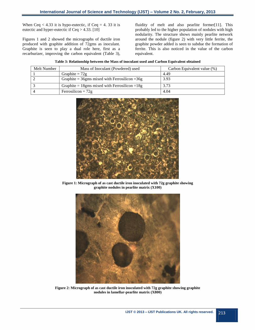
Figures 1 and 2 showed the micrographs of ductile iron
produced with graphite addition of 72gms as inoculant.
Graphite is seen to play a dual role here, first as a
recarburizer, improving the carbon equivalent (Table 3),
fluidity of melt and also pearlite former[11]. This
probably led to the higher population of nodules with high
nodularity. The structure shows mainly pearlite network
around the nodule (figure 2) with very little ferrite, the
graphite powder added is seen to subdue the formation of
ferrite. This is also noticed in the value of the carbon
equivalent.
Table 3: Relationship between the Mass of inoculant used and Carbon Equivalent obtained
Melt Number Mass of Inoculant (Powdered) used Carbon Equivalent value (%)
1 Graphite = 72g 4.49
2 Graphite = 36gms mixed with Ferrosilicon =36g 3.93
3 Graphite = 18gms mixed with Ferrosilicon =18g 3.73
4 Ferrosilicon = 72g 4.04
Figure 1: Micrograph of as cast ductile iron inoculated with 72g graphite showing
graphite nodules in pearlite matrix (X100)
Figure 2: Micrograph of as cast ductile iron inoculated with 72g graphite showing graphite
nodules in lamellar-pearlite matrix (X800)

International Journal of Science and Technology (IJST) – Volume 2 No. 2, February, 2013
IJST © 2013 – IJST Publications UK. All rights reserved. 214
In this particular alloy, it is observed that the graphite
nodules were formed in entirely pearlite matrix as
revealed in Figure 2.
The synergistic effect of using graphite and ferrosilicon as
inoculant is appreciated here. Introducing 36gms of
graphite into the inoculant with 36gms of ferrosilicon
enhanced the formation of ferrite ring around the graphite
nodules in Figures 4 and 5 giving rise to distinct BULLS
EYE structure. The silicon from the ferrosilicon is seen to
initiate the formation of the ferrite [12] and tends to be
slightly forming in the pearlite of the matrix. Similar
effect was also noticed when this inoculant mix was
reduced by half in the ductile iron. This is also a reflection
on the CEV which was 3.93% and 3.73% respectively
typical of hypoeutectic ductile iron (Table 3).
Figure 3: Bar Chart of the Carbon Equivalent versus the Quantity of the Hybrid Inoculant (gms)
Figure 4: Micrograph of as cast ductile iron inoculated with 36g ferrosilicon mixed with
36g graphite showing graphite nodules in pearlite matrix (X100)
KEY (Graphite and FeSi)
A= 72g and 0 g B= 36g and 36g C= 18g and 18g D= 0g and 72g
CARBON EQUIVALENT VALUES VERSUS HYBRID INOCULANT TYPE USED
Car
bo
n E
qu
ival
en
t V
alu
es (
CEV
)
Hybrid Inoculant (g)

International Journal of Science and Technology (IJST) – Volume 2 No. 2, February, 2013
IJST © 2013 – IJST Publications UK. All rights reserved. 215
Figure 5: Micrograph of as cast ductile iron inoculated with 36g graphite and 36g ferrosilicon
showing graphite nodules (bull’s eye) around ferrite in fine pearlite matrix (X800)
Figures 6 and 7 showed the microstructure obtained when
the inoculant mix was reduced to 18gms graphite and
18gms ferrosilicon. It revealed predominantly, the ferrite
ring around the graphite nodule which is observed to
enlarge. The pearlite matrix is seen to be gradually
diminishing with the ferrite surrounding the nodules
within the matrix. The silicon from the ferrosilicon has
again shown its potency for ferrite formation in the ductile
iron. This is typical of a pearlitic - ferritic microstructure
of a ductile iron, produced with other process.
Figure 6: : Micrograph of as cast ductile iron inoculated with 36g graphite and 36g ferrosilicon
showing graphite nodules (bull’s eye) around ferrite in fine pearlite matrix (X100)
International Journal of Science and Technology (IJST) – Volume 2 No. 2, February, 2013
IJST © 2013 – IJST Publications UK. All rights reserved. 216
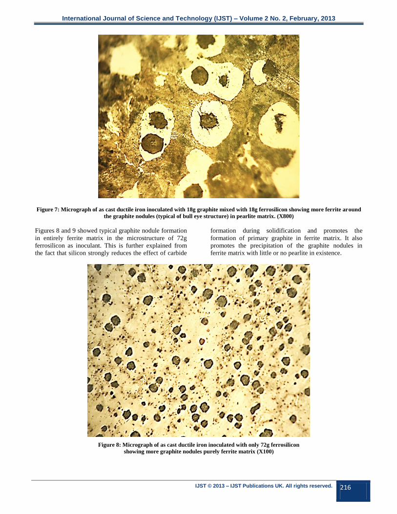
Figure 7: Micrograph of as cast ductile iron inoculated with 18g graphite mixed with 18g ferrosilicon showing more ferrite around
the graphite nodules (typical of bull eye structure) in pearlite matrix. (X800)
Figures 8 and 9 showed typical graphite nodule formation
in entirely ferrite matrix in the microstructure of 72g
ferrosilicon as inoculant. This is further explained from
the fact that silicon strongly reduces the effect of carbide
formation during solidification and promotes the
formation of primary graphite in ferrite matrix. It also
promotes the precipitation of the graphite nodules in
ferrite matrix with little or no pearlite in existence.
Figure 8: Micrograph of as cast ductile iron inoculated with only 72g ferrosilicon
showing more graphite nodules purely ferrite matrix (X100)

International Journal of Science and Technology (IJST) – Volume 2 No. 2, February, 2013
IJST © 2013 – IJST Publications UK. All rights reserved. 217
Figure 9: Micrograph of as cast ductile iron inoculated with only 72g ferrosilicon
showing graphite nodules in purely ferrite matrix (X800)
4. CONCLUSION
Graphite addition as inoculant promotes pearlite
formation while silicon from ferrosilicon enhances ferrite
formation in the matrix of the ductile iron. The synergistic
effect of the secondary addition of carbon (from graphite)
and ferrosilicon inoculation used is responsible for the
pearlitic-ferritic ductile iron without addition of special
alloying element and heat treatment. The ductile iron
microstructure in Figures 4 and 5 with Figures 6 and 7,
where the mixture of powdered 36g of graphite with
36gms of ferrosilicon and 18g of graphite with 18g of
ferrosilicon were used as inoculant are most likely to have
desirable mechanical properties for engineering
application where toughness is required because of the
manifestation of pearlite and ferrite in their matrices.
REFERENCES
[1] Stepanov Y.U.A. and Titov N.D. (1978). Foundry
Practice, Mir Publishers, Russia Pp 256 -257.
[2] LaRoux K. and Gillespie, (1988). Troubleshooting
manufacturing processes (4th ed.), SME, Pg. 4.
[3] Voloshcenko M.V., Ridnyi A.A., Litovka V.I.,
Zelenyi B.G. and Makeeva V.P. (2003). Effect of
Silicon on the Mechanical Properties of Isothermally
Quenched Magnesium Cast Iron. Journal of Metal
Science and Heat Treatment, Springer New York,
Vol. 6 Number 7, P 1.
[4] Imasogie B.I. (1994). Development and
Characterization of Isothermally Heat Treated
Nodular Cast Iron. PhD Thesis, Obafemi Awolowo
University, Ile Ife, Nigeria, P 85.
[5] Ductile Iron Society (2010). Ductile Iron Data for
Design Engineers Pg 1
[6] Ductile Iron Society (2005). Ductile Iron Data for
Design Engineers Pg 1
[7] http://www.Industrialmetalcastings.com (2009).
Melting Furnaces, a publication of Industrial Metal
Casting Company, Ohio.
[8] Adewoye O. O. (2005). EMR100, Focus, Internal
Magazine, Engineering Materials Development
Institute, Akure, Nigeria, Pg 3
[9] http://www.foundry.elkem.com (2004). Inoculation
Practices, Elkem Foundry Products, Technical
Information 4, Norway
[10] Henderieckx Gietech (2008). Ductile Iron
Solidification Mechanism, Pp 1-27.
[11] Rourke Robert O’, (2001). Cast Iron: The
Engineered Metal. Advance Materials and Processes,
DuraBar, Woodstock, Illinois, Pg67.
[12] Magnus Wessen (1997). On the Mechanism of
Structure Formation in Nodular Cast Iron, KTH
Publication, Sweden. Pg. 26