joytork - rutschkupplungen joytork - torque limiters
TRANSCRIPT
�
®
®
g
Z
Anzahl der
Einstell-
schrauben
Number of
adjustment
screws
JOYTORK® - RutschkupplungenJoytork ® - Torque Limiters
Bauformen und Einsatzbereiche Types of torque limiters and applications
Antriebstechnik • Hydraulik-Komponenten • Ölkühler Transmission Engineering • Hydraulic-Components • Oil-coolers
�
®
®
Bauformen und Einsatzbereiche Types of torque limiters and applications
Beschreibung Description Einsatzbereiche Applications
JOY
TOR
K®
Sta
ndar
dS
tand
ard
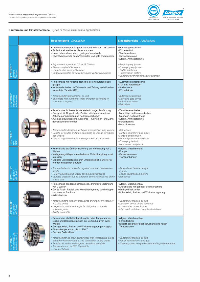
• Drehmomentbegrenzung für Momente von 0,5 – �3.000 Nm• Stufenlos einstellbares Rutschmoment• Hohe Lebensdauer durch geringen Verschleiß• Oberflächenschutz durch Verzinkten und gelb chromatieren
• Adjustable torque from 0.5 to 23.000 Nm• Stepless adjustable torque• Long life due to very little wear• Surface protected by galvanizing and yellow cromatizing
• Recyclingmaschinen• Fördertechnik• Textilmaschinen• Getriebemotoren• Allgem. Antriebstechnik
• Recycling equipment• Conveying equipment• Textile machines• Transmission motors• General power transmission equipment
JOY
TOR
K®
mit
Ket
tenr
adw
ith s
proc
ket
• Rutschnabe mit Kettenradscheibe als einbaufertige Bau-gruppe
• Kettenradscheiben in Zähnezahl und Teilung nach Kunden-wunsch (s. Tabelle KRS)
• Torque limiter with sprocket as unit• Sprockets with number of teeth and pitch according to
customer‘s request
• Automatisierungstechnik• Tür- und Torantriebe• Stellantriebe• Förderbänder
• Automatic equipment• Door and gate drives• Adjustment drives• Belt drives
JOY
TOR
K®
MA
XM
AX
• Rutschnabe für breite Antriebsteile in langer Ausführung• Geeignet für Doppel- oder Dreifach-Kettenradscheiben,
Zahnriemenscheiben und Keilriemenscheiben• Auch als Baugruppe mit Kettenrad- , Keilriemen- und Zahn-
riemenscheibe lieferbar
• Torque limiter designed for broad drive parts in long version• Usable for double and triple sprockets as well as for rubber
belt wheels• Can be supplied complete with sprocket or belt wheels
• Zahnriemenscheiben• Mehrrillige Keilriemenscheiben• Mehrfach-Kettenantriebe• Allgem. Antriebstechnik• Fördertechnik• Maschinenbau
• Belt wheels• Multiple chamfer v-belt pulley• Multiple chain drives• General power transmission• Conveying technic• Mechanical equipment
JOY
TOR
K®
mit
Spi
dex®
with
Spi
dex®
• Rutschnabe als Überlastsicherung zur Verbindung von � Wellen
• Verlagerungsfähige, drehelastische Rutschkupplung, axial streckbar
• Variable Drehelastizität durch unterschiedliche Shore-Här-ten der elastischen Bauteile
• Torque limiter for protection against overload between two shafts
• Rotary elastic torque limiter can be axialy streched• Variable elasticity due to differenrt Shore Hardnesses of the
elastic part
• Allgem. Maschinenbau• Pumpen• Getriebemotoren• Transportbänder
• General mechanical design• Pumps• Power transmission motors• Belt drives
JOY
TOR
K®
mit
Den
tex®
with
Den
tx®
• Rutschnabe als doppelkardanische, drehsteife Verbindung von � Wellen
• Große Axial-, Radial- und Winkelverlagerung durch doppel-kardanische Bauform
• Axial steckbar
• Torque limiters with universal joints and rigid connection of two axle shafts
• Large axial, radial and angle flexibility due to double universal joints
• Axially assemble
• Allgem. Maschinenbau• Antriebsfälle mit geringer Beanspruchung• Geringe Drehzahlen• Hohe Axial-, Radial- und Winkelverlagerung
• General mechanical design• Design of drives of low demands• Low number of revolutions• High axial, radial and angular deviations
JOY
TOR
K®
mit
Ket
tenk
uppl
ung
with
cha
in c
oupl
ing
• Rutschnabe als Kettenkupplung für hohe Temperaturbe-reiche und Beanspruchungen zur Verbindung von zwei Wellen
• Geringe Axial-, Radial- und Winkelverlagerungen möglich• Einsatztemperaturen bis zu �80°C• Geringe Drehzahlen
• Torque limiter as chain coupling for high temperature areas and other high demand for the connection of two shafts
• Small axail, radial and angular deviations possible• Temperature up to 280° C possible• Low revolutions
• Allgem. Maschinenbau• Fördertechnik• Einsatz bei großer Beanspruchung und hohen
Temperaturen
• General mechanical design• Power transmission tecnique• When exposed to high demand and high temperature
Antriebstechnik • Hydraulik-Komponenten • Ölkühler Transmission Engineering • Hydraulic-Components • Oil-coolers
3
®
®
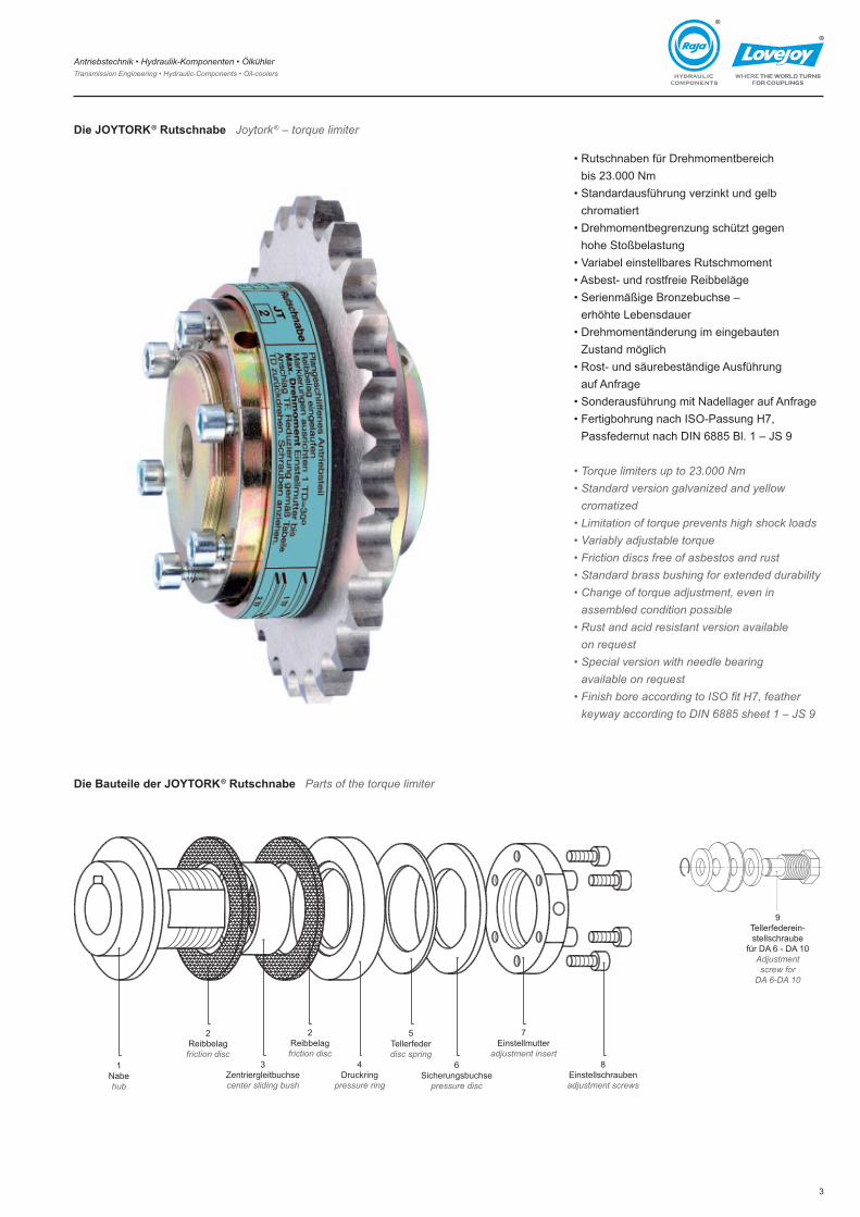
Die JOYTORK® Rutschnabe Joytork® – torque limiter
• Rutschnaben für Drehmomentbereich bis �3.000 Nm
• Standardausführung verzinkt und gelb chromatiert
• Drehmomentbegrenzung schützt gegen hohe Stoßbelastung
• Variabel einstellbares Rutschmoment• Asbest- und rostfreie Reibbeläge• Serienmäßige Bronzebuchse –
erhöhte Lebensdauer• Drehmomentänderung im eingebauten
Zustand möglich• Rost- und säurebeständige Ausführung
auf Anfrage• Sonderausführung mit Nadellager auf Anfrage• Fertigbohrung nach ISO-Passung H7,
Passfedernut nach DIN 6885 Bl. � – JS 9
• Torque limiters up to 23.000 Nm• Standard version galvanized and yellow
cromatized• Limitation of torque prevents high shock loads • Variably adjustable torque• Friction discs free of asbestos and rust• Standard brass bushing for extended durability • Change of torque adjustment, even in
assembled condition possible • Rust and acid resistant version available
on request• Special version with needle bearing
available on request• Finish bore according to ISO fit H7, feather
keyway according to DIN 6885 sheet 1 – JS 9
Die Bauteile der JOYTORK® Rutschnabe Parts of the torque limiter
�Nabehub
�Reibbelagfriction disc
3Zentriergleitbuchsecenter sliding bush
�Reibbelagfriction disc
4Druckring
pressure ring
5Tellerfederdisc spring
6Sicherungsbuchse
pressure disc
7Einstellmutter
adjustment insert8
Einstellschraubenadjustment screws
9Tellerfederein-stellschraube
für DA 6 - DA �0Adjustment screw for
DA 6-DA 10
Antriebstechnik • Hydraulik-Komponenten • Ölkühler Transmission Engineering • Hydraulic-Components • Oil-coolers
4
®
®
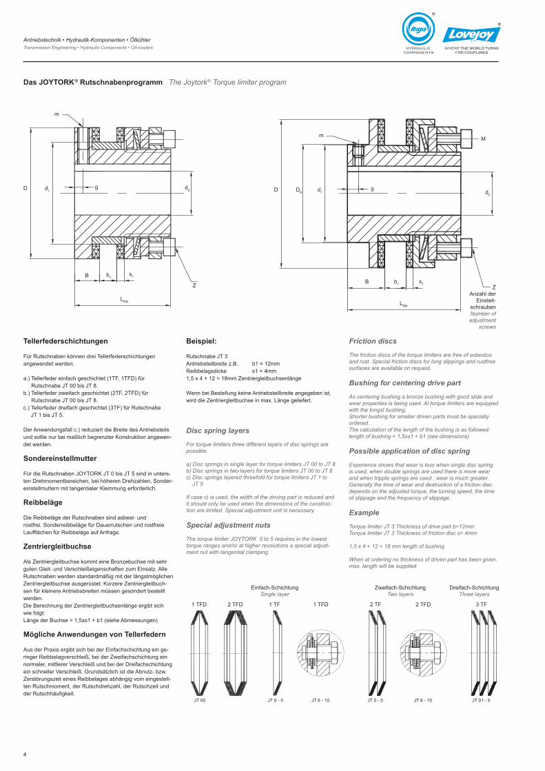
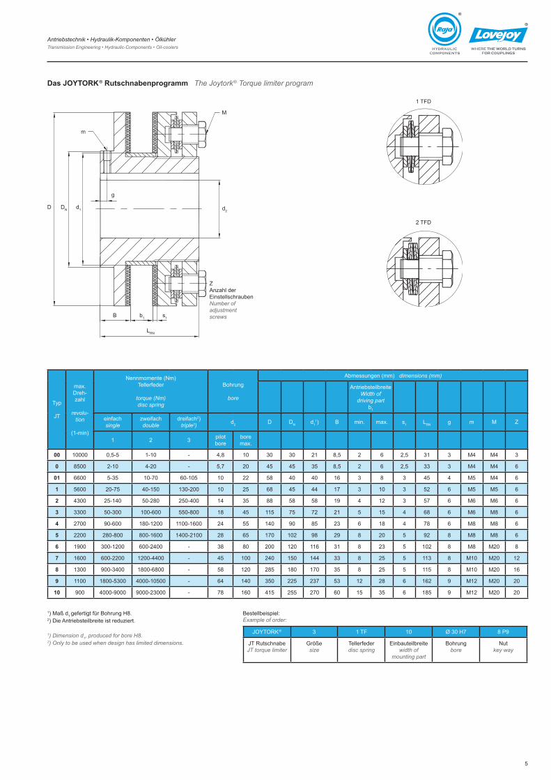
Das JOYTORK® Rutschnabenprogramm The Joytork® Torque limiter program
Tellerfederschichtungen
Für Rutschnaben können drei Tellerfederschichtungen angewendet werden.
a.) Tellerfeder einfach geschichtet (�TF, �TFD) für Rutschnabe JT 00 bis JT 8.
b.) Tellerfeder zweifach geschichtet (�TF, �TFD) für Rutschnabe JT 00 bis JT 8.
c.) Tellerfeder dreifach geschichtet (3TF) für Rutschnabe JT � bis JT 5.
Der Anwendungsfall c.) reduziert die Breite des Antriebsteils und sollte nur bei maßlich begrenzter Konstruktion angewen-det werden.
Sondereinstellmutter
Für die Rutschnaben JOYTORK JT 0 bis JT 5 sind in unters-ten Drehmomentbereichen, bei höheren Drehzahlen, Sonder-einstellmuttern mit tangentialer Klemmung erforderlich.
Reibbeläge
Die Reibbeläge der Rutschnaben sind asbest- und rostfrei. Sonderreibbeläge für Dauerrutschen und rostfreie Laufflächen für Reibbeläge auf Anfrage.
Zentriergleitbuchse
Als Zentriergleitbuchse kommt eine Bronzebuchse mit sehr guten Gleit- und Verschleißeigenschaften zum Einsatz. Alle Rutschnaben werden standardmäßig mit der längstmöglichen Zentriergleitbuchse ausgerüstet. Kürzere Zentriergleitbuch-sen für kleinere Antriebsbreiten müssen gesondert bestellt werden.Die Berechnung der Zentriergleitbuchsenlänge ergibt sich wie folgt: Länge der Buchse = 1,5xs1 + b1 (siehe Abmessungen)
Mögliche Anwendungen von Tellerfedern
Aus der Praxis ergibt sich bei der Einfachschichtung ein ge-ringer Reibbelagverschleiß, bei der Zweifachschichtung ein normaler, mittlerer Verschleiß und bei der Dreifachschichtung ein schneller Verschleiß. Grundsätzlich ist die Abnutz- bzw. Zerstörungszeit eines Reibbelages abhängig vom eingestell-ten Rutschmoment, der Rutschdrehzahl, der Rutschzeit und der Rutschhäufigkeit.
Beispiel:
Rutschnabe JT 3Antriebsteilbreite z.B. b1 = 12mmReibbelagsdicke s1 = 4mm1,5 x 4 + 12 = 18mm Zentriergleitbuchsenlänge
Wenn bei Bestellung keine Antriebsteilbreite angegeben ist, wird die Zentriergleitbuchse in max. Länge geliefert.
Disc spring layers
For torque limiters three different layers of disc springs are possible.
a) Disc springs in single layer for torque limiters JT 00 to JT 8b) Disc springs in two layers for torque limiters JT 00 to JT 8c) Disc springs layered threefold for torque limiters JT 1 to
JT 5
If case c) is used, the width of the driving part is reduced and it should only be used when the dimensions of the construc-tion are limited. Special adjustment unit is necessary.
Special adjustment nuts
The torque limiter JOYTORK 0 to 5 requires in the lowest torque ranges and/or at higher revolutions a special adjust-ment nut with tangential clamping.
d�d�D g
m
B b�s�
LRN
Z
D DN d�g
m
d�
M
B b� s�
LRN
Z Anzahl der
Einstell-schraubenNumber of adjustment
screws
� TFD � TFD � TF � TFD � TFD� TF 3 TF
Einfach-SchichtungSingle layer
Zweifach-SchichtungTwo layers
Dreifach-SchichtungThree layers
JT 00 JT 0 - 5 JT 6 - �0 JT 0 - 5 JT 6 - �0 JT 0� - 5
Friction discs
The friction discs of the torque limiters are free of asbestos and rust. Special friction discs for long slippings and rustfree surfaces are available on request.
Bushing for centering drive part
As centering bushing a bronze bushing with good slide and wear properties is being used. Al torque limiters are equipped with the longst bushing. Shorter bushing for smaller driven parts must be specially ordered.The calculation of the length of the bushing is as followed: length of bushing = 1,5xs1 + b1 (see dimensions)
Possible application of disc spring
Experience shows that wear is less when single disc spring is used, when double springs are used there is more wear and when tripple springs are used , wear is much greater. Generally the time of wear and destruction of a friction disc depends on the adjusted torque, the turning speed, the time of slippage and the frequency of slippage.
Example
Torque limiter JT 3 Thickness of drive part b=12mmTorque limiter JT 3 Thickness of friction disc s= 4mm
1,5 x 4 + 12 = 18 mm length of bushing
When at ordering no thickness of driven part has been given, max. length will be supplied.
Antriebstechnik • Hydraulik-Komponenten • Ölkühler Transmission Engineering • Hydraulic-Components • Oil-coolers
5
®
®
Das JOYTORK® Rutschnabenprogramm The Joytork® Torque limiter program
Typ
JT
max. Dreh-zahl
revolu-tion
(�-min)
Nennmomente (Nm)Tellerfeder
torque (Nm)disc spring
Bohrung
bore
Abmessungen (mm) dimensions (mm)
AntriebsteilbreiteWidth of
driving partb�
einfachsingle
zweifachdouble
dreifach�)triple2) d� D DN d�
�) B min. max. s� LRN g m M Z
� � 3 pilot bore
bore max.
00 �0000 0,5-5 �-�0 - 4,8 �0 30 30 �� 8,5 � 6 �,5 3� 3 M4 M4 3
0 8500 �-�0 4-�0 - 5,7 �0 45 45 35 8,5 � 6 �,5 33 3 M4 M4 6
01 6600 5-35 �0-70 60-�05 �0 �� 58 40 40 �6 3 8 3 45 4 M5 M4 6
1 5600 �0-75 40-�50 �30-�00 �0 �5 68 45 44 �7 3 �0 3 5� 6 M5 M5 6
2 4300 �5-�40 50-�80 �50-400 �4 35 88 58 58 �9 4 �� 3 57 6 M6 M6 6
3 3300 50-300 �00-600 550-800 �8 45 ��5 75 7� �� 5 �5 4 68 6 M6 M8 6
4 �700 90-600 �80-��00 ��00-�600 �4 55 �40 90 85 �3 6 �8 4 78 6 M8 M8 6
5 ��00 �80-800 800-�600 �400-��00 �8 65 �70 �0� 98 �9 8 �0 5 9� 8 M8 M8 6
6 �900 300-��00 600-�400 - 38 80 �00 ��0 ��6 3� 8 �3 5 �0� 8 M8 M�0 8
7 �600 600-��00 ��00-4400 - 45 �00 �40 �50 �44 33 8 �5 5 ��3 8 M�0 M�0 ��
8 �300 900-3400 �800-6800 - 58 ��0 �85 �80 �70 35 8 �5 5 ��5 8 M�0 M�0 �6
9 ��00 �800-5300 4000-�0500 - 64 �40 350 ��5 �37 53 �� �8 6 �6� 9 M�� M�0 �0
10 900 4000-9000 9000-�3000 - 78 �60 4�5 �55 �70 60 �5 35 6 �85 9 M�� M�0 �0
�) Maß d� gefertigt für Bohrung H8. �) Die Antriebsteilbreite ist reduziert.
1) Dimension d1, produced for bore H8.2) Only to be used when design has limited dimensions.
Bestellbeispiel:Example of order:
JOYTORK® 3 � TF �0 Ø 30 H7 8 P9
JT RutschnabeJT torque limiter
Größesize
Tellerfederdisc spring
Einbauteilbreitewidth of
mounting part
Bohrungbore
Nutkey way
D DN d�
B b� s�
LRN
g
d�
m
M
ZAnzahl der EinstellschraubenNumber of adjustment screws
� TFD
� TFD
Antriebstechnik • Hydraulik-Komponenten • Ölkühler Transmission Engineering • Hydraulic-Components • Oil-coolers
6
®
®
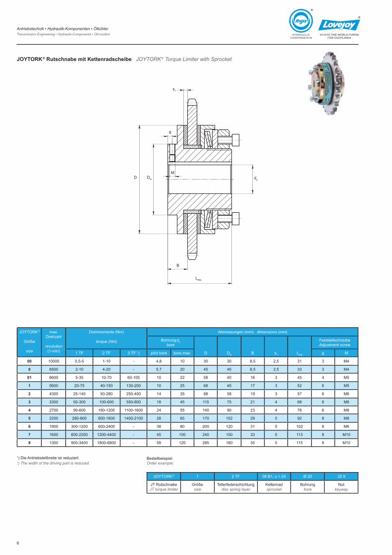
JOYTORK® Rutschnabe mit Kettenradscheibe JOYTORK® Torque Limiter with Sprocket
JOYTORK®
Größe
size
max. Drehzahl
revolution(�-min)
Drehmomente (Nm)
torque (Nm)
Abmessungen (mm) dimensions (mm)
Bohrung d�bore
D DN B s� LRN
FeststellschraubeAdjustment screw
� TF � TF 3 TF �) pilot bore bore max. g M
00 �0000 0,5-5 �-�0 - 4,8 �0 30 30 8,5 �,5 3� 3 M4
0 8500 �-�0 4-�0 - 5,7 �0 45 45 8,5 �,5 33 3 M4
01 6600 5-35 �0-70 60-�05 �0 �� 58 40 �6 3 45 4 M5
1 5600 �0-75 40-�50 �30-�00 �0 �5 68 45 �7 3 5� 6 M5
2 4300 �5-�40 50-�80 �50-400 �4 35 88 58 �9 3 57 6 M6
3 3300 50-300 �00-600 550-800 �8 45 ��5 75 �� 4 68 6 M6
4 �700 90-600 �80-��00 ��00-�600 �4 55 �40 90 �3 4 78 6 M8
5 ��00 �80-800 800-�600 �400-��00 �8 65 �70 �0� �9 5 9� 8 M8
6 �900 300-��00 600-�400 - 38 80 �00 ��0 3� 5 �0� 8 M6
7 �600 600-��00 ��00-4400 - 45 �00 �40 �50 33 5 ��3 8 M�0
8 �300 900-3400 �800-6800 - 58 ��0 �85 �80 35 5 ��5 8 M�0
DNDM
g
s�
d�
LRN
B
�) Die Antriebsteilbreite ist reduziert.1) The width of the driving part is reduced.
Bestellbeispiel:Order example:
JOYTORK® � � TF 08 B1, z = 24 Ø �0 JS 9
JT RutschnabeJT torque limiter
Größe size
Tellerfederschichtungdisc spring layer
Kettenradsprocket
Bohrungbore
Nutkeyway
Antriebstechnik • Hydraulik-Komponenten • Ölkühler Transmission Engineering • Hydraulic-Components • Oil-coolers
7
®
®
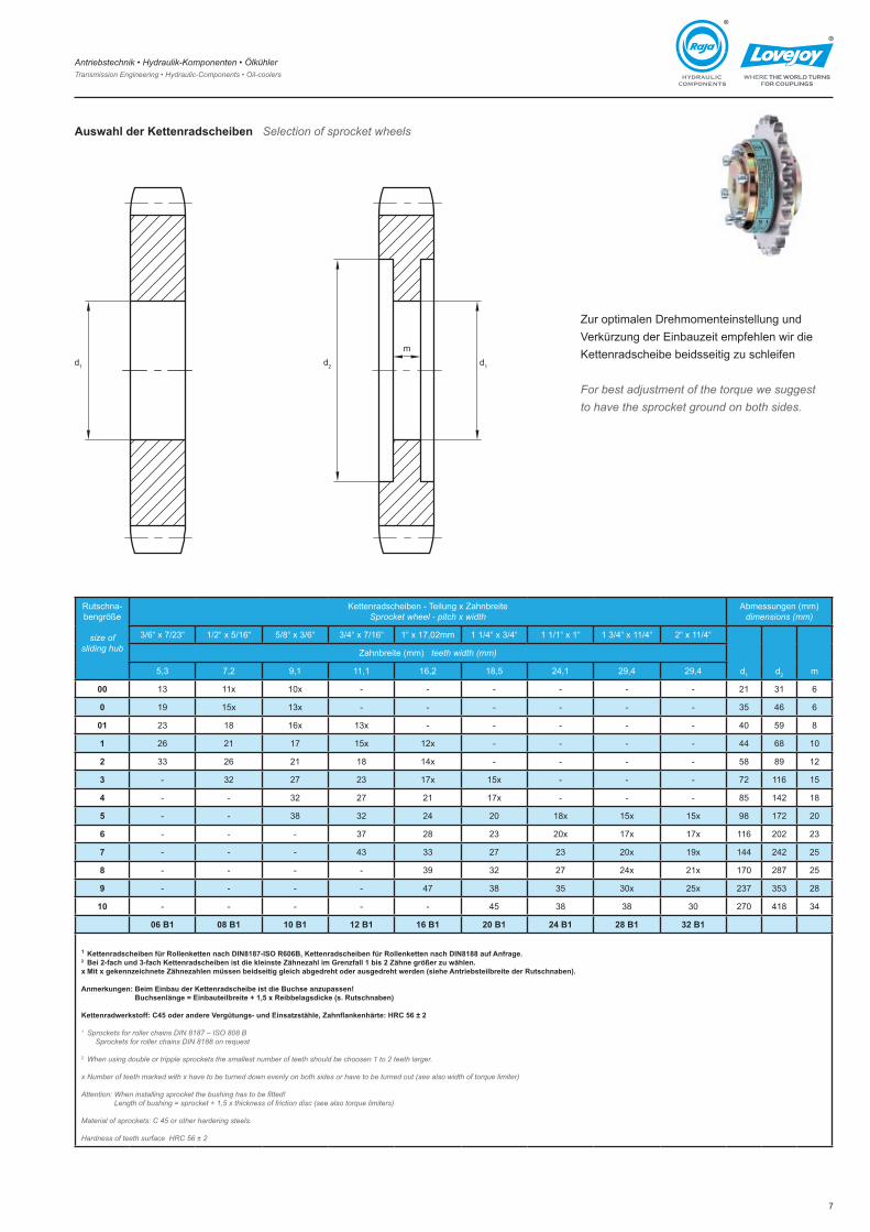
Auswahl der Kettenradscheiben Selection of sprocket wheels
Zur optimalen Drehmomenteinstellung und Verkürzung der Einbauzeit empfehlen wir die Kettenradscheibe beidsseitig zu schleifen
For best adjustment of the torque we suggest to have the sprocket ground on both sides.
Rutschna-bengröße
size ofsliding hub
Kettenradscheiben - Teilung x ZahnbreiteSprocket wheel - pitch x width
Abmessungen (mm)dimensions (mm)
3/6“ x 7/�3“ �/�“ x 5/�6“ 5/8“ x 3/6“ 3/4“ x 7/�6“ �“ x �7,0�mm � �/4“ x 3/4“ � �/�“ x �“ � 3/4“ x ��/4“ �“ x ��/4“
d� d� m
Zahnbreite (mm) teeth width (mm)
5,3 7,� 9,� ��,� �6,� �8,5 �4,� �9,4 �9,4
00 �3 ��x �0x - - - - - - �� 3� 6
0 �9 �5x �3x - - - - - - 35 46 6
01 �3 �8 �6x �3x - - - - - 40 59 8
1 �6 �� �7 �5x ��x - - - - 44 68 �0
2 33 �6 �� �8 �4x - - - - 58 89 ��
3 - 3� �7 �3 �7x �5x - - - 7� ��6 �5
4 - - 3� �7 �� �7x - - - 85 �4� �8
5 - - 38 3� �4 �0 �8x �5x �5x 98 �7� �0
6 - - - 37 �8 �3 �0x �7x �7x ��6 �0� �3
7 - - - 43 33 �7 �3 �0x �9x �44 �4� �5
8 - - - - 39 3� �7 �4x ��x �70 �87 �5
9 - - - - 47 38 35 30x �5x �37 353 �8
10 - - - - - 45 38 38 30 �70 4�8 34
06 B1 08 B1 10 B1 12 B1 16 B1 20 B1 24 B1 28 B1 32 B1
1 Kettenradscheiben für Rollenketten nach DIN8187-ISO R606B, Kettenradscheiben für Rollenketten nach DIN8188 auf Anfrage.2 Bei 2-fach und 3-fach Kettenradscheiben ist die kleinste Zähnezahl im Grenzfall 1 bis 2 Zähne größer zu wählen.x Mit x gekennzeichnete Zähnezahlen müssen beidseitig gleich abgedreht oder ausgedreht werden (siehe Antriebsteilbreite der Rutschnaben).
Anmerkungen: Beim Einbau der Kettenradscheibe ist die Buchse anzupassen! Buchsenlänge = Einbauteilbreite + 1,5 x Reibbelagsdicke (s. Rutschnaben)
Kettenradwerkstoff: C45 oder andere Vergütungs- und Einsatzstähle, Zahnflankenhärte: HRC 56 ± 2
1 Sprockets for roller chains DIN 8187 – ISO 808 B Sprockets for roller chains DIN 8188 on request
2 When using double or tripple sprockets the smallest number of teeth should be choosen 1 to 2 teeth larger.
x Number of teeth marked with x have to be turned down evenly on both sides or have to be turned out (see also width of torque limiter)
Attention: When installing sprocket the bushing has to be fitted! Length of bushing = sprocket + 1,5 x thickness of friction disc (see also torque limiters)
Material of sprockets: C 45 or other hardering steels.
Hardness of teeth surface HRC 56 ± 2
d� d�
md�
Antriebstechnik • Hydraulik-Komponenten • Ölkühler Transmission Engineering • Hydraulic-Components • Oil-coolers
8
®
®
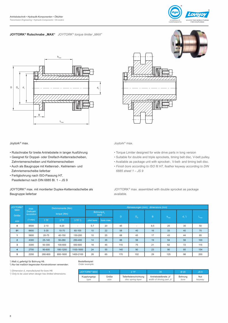
JOYTORK® Rutschnabe „MAX“ JOYTORK® torque limiter „MAX“
Joytork® max.
• Rutschnabe für breite Antriebsteile in langer Ausführung• Geeignet für Doppel- oder Dreifach-Kettenradscheiben,
Zahnriemenscheiben und Keilriemenscheiben• Auch als Baugruppe mit Kettenrad-, Keilriemen- und
Zahnriemenscheibe lieferbar• Fertigbohrung nach ISO-Passung H7,
Passfedernut nach DIN 6885 Bl. � – JS 9
JOYTORK® max. mit montierter Duplex-Kettenradscheibe als Baugruppe lieferbar
JOYTORK®
MAX
Größe
size
max. Drehzahlrevolution
(�-min)
Drehmomente (Nm)
torque (Nm)
Abmessungen (mm) dimensions (mm)
Bohrung d� bore
D DN B bmax d� �) Lmax
� TF � TF 3 TF �) pilot bore bore max.
0 8500 �-�0 4-�0 - 5,7 �0 45 - 8,5 �5 35 50
01 6600 5-35 �0-70 60-�05 �0 �� 58 40 �6 33 40 70
1 5600 �0-75 40-�50 �30-�00 �0 �5 68 45 �7 43 44 85
2 4300 �5-�40 50-�80 �50-400 �4 35 88 58 �9 54 58 �00
3 3300 50-300 �00-600 550-800 �8 45 ��5 75 �� 6� 7� ��5
4 �700 90-600 �80-��00 ��00-�600 �4 55 �40 90 �3 90 85 �54
5 ��00 �80-800 800-�600 �400-��00 �8 65 �70 �0� �9 ��5 98 �00
Bestellbeispiel:Order example:
JOYTORK® MAX � � TF 35 Ø �0 JS 9
Kupplungstyptype
Größesize
Tellerfederschichtungdisc spring layer
Antriebsteilbreite „b“width of driving part „b“
Bohrungbore
Nutkeyway
�) Maß d� gefertigt für Bohrung H8.�) Nur bei maßlich begrenzten Konstruktionen verwenden. 1) Dimension d1 manufactured for bore H8.2) Only to be used when design has limited dimensions.
D DN d�
Lmax
d�
bmax
B
Joytork® max.
• Torque Limiter designed for wide drive parts in long version• Suitable for double and triple sprockets, timing belt disc, V-belt pulley.• Available as package unit with sprocket-, V-belt- and timing belt disc.• Finish bore according to ISO fit H7, feather keyway according to DIN
6885 sheet 1 – JS 9
JOYTORK® max. assembled with double sprocket as package available.
Antriebstechnik • Hydraulik-Komponenten • Ölkühler Transmission Engineering • Hydraulic-Components • Oil-coolers
9
®
®
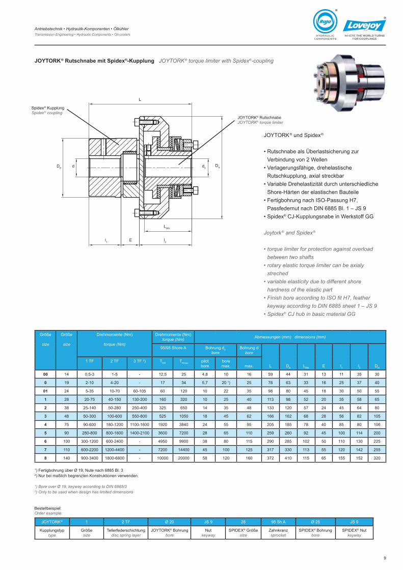
Größe
size
Größe
size
Drehmomente (Nm)
torque (Nm)
Drehmomente (Nm)torque (Nm) Abmessungen (mm) dimensions (mm)
95/98 Shore A Bohrung d�bore
Bohrung dbore
L DA LRN E l� l� DH
� TF � TF 3 TF �) TKN TKmax pilot bore
bore max. max.
00 �4 0,5-3 �-5 - ��,5 �5 4,8 �0 �6 59 44 3� �3 �� 35 30
0 �9 �-�0 4-�0 - �7 34 5,7 �0 �) �5 78 63 33 �6 �5 37 40
01 �4 5-35 �0-70 60-�05 60 ��0 �0 �� 35 98 80 45 �8 30 50 55
1 �8 �0-75 40-�50 �30-�00 �60 3�0 �0 �5 40 ��3 98 5� �0 35 58 65
2 38 �5-�40 50-�80 �50-400 3�5 650 �4 35 48 �33 ��0 57 �4 45 64 80
3 48 50-300 �00-600 550-800 5�5 �050 �8 45 6� �66 �6� 68 �8 56 8� �05
4 75 90-600 �80-��00 ��00-�600 �9�0 3840 �4 55 95 �05 �85 78 40 85 80 �06
5 90 �80-800 800-�600 �400-��00 3600 7�00 �8 65 ��0 �59 �60 9� 45 �00 ��4 �00
6 �00 300-��00 600-�400 - 4950 9900 38 80 ��5 �90 �85 �0� 50 ��0 �30 ��5
7 ��0 600-��00 ��00-4400 - 7�00 �4400 45 �00 ��5 3�7 330 ��3 55 ��0 �4� �55
8 �40 900-3400 �800-6800 - �0000 �0000 58 ��0 �60 37� 4�0 ��5 65 �55 �5� 3�0
�) Fertigbohrung über Ø �9, Nute nach 6885 Bl. 3�) Nur bei maßlich begrenzten Konstruktionen verwenden.
1) Bore over Ø 19, keyway according to DIN 6885/32) Only to be used when design has limited dimensions
DH d
l� l�E
LRN
d�DA
L
Spidex® KupplungSpidex® coupling
JOYTORK® RutschnabeJOYTORK® torque limiter
JOYTORK® und Spidex®
• Rutschnabe als Überlastsicherung zur Verbindung von � Wellen
• Verlagerungsfähige, drehelastische Rutschkupplung, axial streckbar
• Variable Drehelastizität durch unterschiedliche Shore-Härten der elastischen Bauteile
• Fertigbohrung nach ISO-Passung H7, Passfedernut nach DIN 6885 Bl. � – JS 9
• Spidex® CJ-Kupplungsnabe in Werkstoff GG
Joytork® and Spidex®
• torque limiter for protection against overload between two shafts
• rotary elastic torque limiter can be axialy streched
• variable elasticity due to different shore hardness of the elastic part
• Finish bore according to ISO fit H7, feather keyway according to DIN 6885 sheet 1 – JS 9
• Spidex® CJ hub in basic material GG
Bestellbeispiel:Order example:
JOYTORK® � � TF Ø �0 JS 9 �8 98 Sh A Ø �5 JS 9
Kupplungstyptype
Größesize
Tellerfederschichtungdisc spring layer
JOYTORK® Bohrungbore
Nutkeyway
SPIDEX® Größe size
Zahnkranzsprocket
SPIDEX® Bohrungbore
SPIDEX® Nutkeyway
JOYTORK® Rutschnabe mit Spidex®-Kupplung JOYTORK® torque limiter with Spidex®-coupling
Antriebstechnik • Hydraulik-Komponenten • Ölkühler Transmission Engineering • Hydraulic-Components • Oil-coolers
�0
®
®
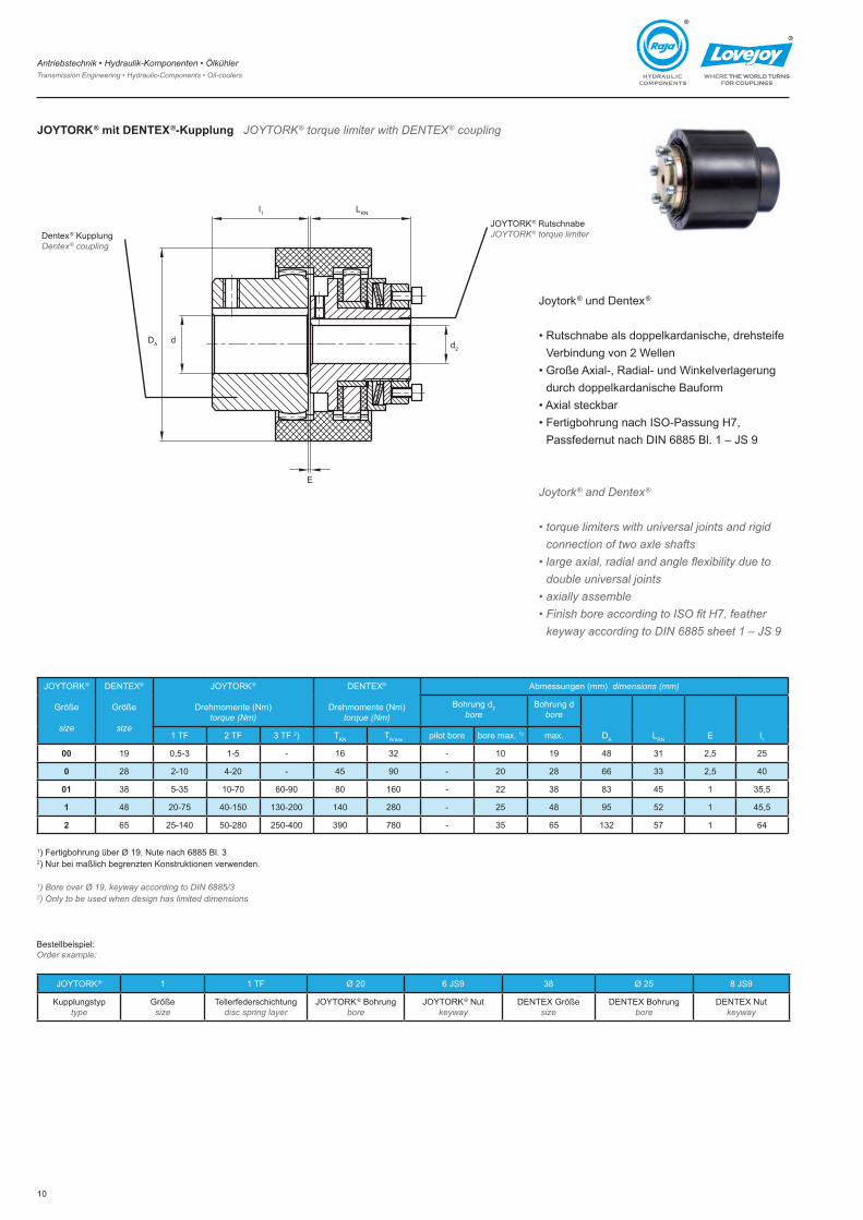
JOYTORK® mit DENTEX®-Kupplung JOYTORK® torque limiter with DENTEX® coupling
JOYTORK®
Größe
size
DENTEX®
Größe
size
JOYTORK®
Drehmomente (Nm)torque (Nm)
DENTEX®
Drehmomente (Nm)torque (Nm)
Abmessungen (mm) dimensions (mm)
Bohrung d�bore
Bohrung dbore
DA LRN E l�� TF � TF 3 TF �) TKN TKmax pilot bore bore max. �) max.
00 �9 0,5-3 �-5 - �6 3� - �0 �9 48 3� �,5 �5
0 �8 �-�0 4-�0 - 45 90 - �0 �8 66 33 �,5 40
01 38 5-35 �0-70 60-90 80 �60 - �� 38 83 45 � 35,5
1 48 �0-75 40-�50 �30-�00 �40 �80 - �5 48 95 5� � 45,5
2 65 �5-�40 50-�80 �50-400 390 780 - 35 65 �3� 57 � 64
Joytork® und Dentex®
• Rutschnabe als doppelkardanische, drehsteife Verbindung von � Wellen
• Große Axial-, Radial- und Winkelverlagerung durch doppelkardanische Bauform
• Axial steckbar• Fertigbohrung nach ISO-Passung H7,
Passfedernut nach DIN 6885 Bl. � – JS 9
Joytork® and Dentex®
• torque limiters with universal joints and rigid connection of two axle shafts
• large axial, radial and angle flexibility due to double universal joints
• axially assemble • Finish bore according to ISO fit H7, feather
keyway according to DIN 6885 sheet 1 – JS 9
Dentex® KupplungDentex® coupling
JOYTORK® RutschnabeJOYTORK® torque limiter
DA d d�
LRNl�
E
Bestellbeispiel:Order example:
JOYTORK® � � TF Ø �0 6 JS9 38 Ø �5 8 JS9
Kupplungstyptype
Größesize
Tellerfederschichtungdisc spring layer
JOYTORK® Bohrungbore
JOYTORK® Nutkeyway
DENTEX Größesize
DENTEX Bohrungbore
DENTEX Nutkeyway
�) Fertigbohrung über Ø �9, Nute nach 6885 Bl. 3�) Nur bei maßlich begrenzten Konstruktionen verwenden.
1) Bore over Ø 19, keyway according to DIN 6885/32) Only to be used when design has limited dimensions
Antriebstechnik • Hydraulik-Komponenten • Ölkühler Transmission Engineering • Hydraulic-Components • Oil-coolers
��
®
®
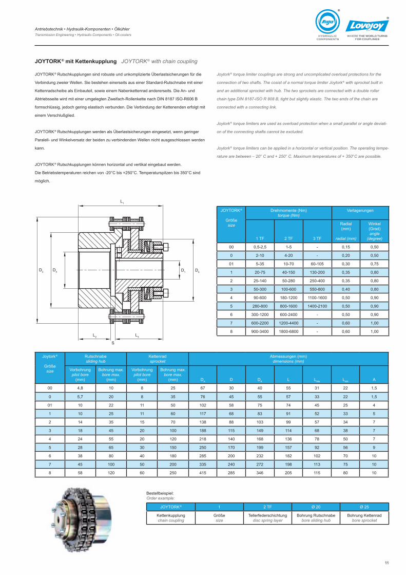
JOYTORK® mit Kettenkupplung JOYTORK® with chain coupling
JOYTORK® Rutschkupplungen sind robuste und unkomplizierte Überlastsicherungen für die
Verbindung zweier Wellen. Sie bestehen einerseits aus einer Standard-Rutschnabe mit einer
Kettenradscheibe als Einbauteil, sowie einem Nabenkettenrad andererseits. Die An- und
Abtriebsseite wird mit einer umgelegten Zweifach-Rollenkette nach DIN 8187 ISO-R606 B
formschlüssig, jedoch gering elastisch verbunden. Die Verbindung der Kettenenden erfolgt mit
einem Verschlußglied.
JOYTORK® Rutschkupplungen werden als Überlastsicherungen eingesetzt, wenn geringer
Paralell- und Winkelversatz der beiden zu verbindenden Wellen nicht ausgeschlossen werden
kann.
JOYTORK® Rutschkupplungen können horizontal und vertikal eingebaut werden.
Die Betriebstemperaturen reichen von -20°C bis +250°C. Temperaturspitzen bis 350°C sind
möglich.
Joytork® torque limiter couplings are strong and uncomplicated overload protections for the
connection of two shafts. The cosist of a normal torque limiter Joytork® with sprocket built in
and an additional sprocket with hub. The two sprockets are connected with a double roller
chain type DIN 8187-ISO R 808 B, tight but slightly elastic. The two ends of the chain are
connected with a connecting link.
Joytork® torque limiters are used as overload protection when a small parallel or angle deviati-
on of the connecting shafts cannot be excluded.
Joytork® torque limiters can be applied in a horizontal or vertical position. The operating tempe-
rature are between – 20° C and + 250° C. Maximum temperatures of + 350°C are possible.
JOYTORK®
Größesize
Drehmomente (Nm)torque (Nm)
Verlagerungen
� TF � TF 3 TF
Radial(mm)
radial (mm)
Winkel(Grad)angle
(degree)
00 0,5-�,5 �-5 - 0,�5 0,50
0 �-�0 4-�0 - 0,�0 0,50
0� 5-35 �0-70 60-�05 0,30 0,75
� �0-75 40-�50 �30-�00 0,35 0,80
� �5-�40 50-�80 �50-400 0,35 0,80
3 50-300 �00-600 550-800 0,40 0,80
4 90-600 �80-��00 ��00-�600 0,50 0,90
5 �80-800 800-�600 �400-��00 0,50 0,90
6 300-��00 600-�400 - 0,50 0,90
7 600-��00 ��00-4400 - 0,60 �,00
8 900-3400 �800-6800 - 0,60 �,00
Joytork®
Größesize
Rutschnabesliding hub
Kettenradsprocket
Abmessungen (mm)dimensions (mm)
Vorbohrungpilot bore
(mm)
Bohrung max.bore max.
(mm)
Vorbohrungpilot bore
(mm)
Bohrung max.bore max.
(mm) DA D DK L LRN LKR A
00 4,8 �0 8 �5 67 30 40 55 3� �� �,5
0 5,7 �0 8 35 76 45 55 57 33 �� �,5
0� �0 �� �� 50 �0� 58 75 74 45 �5 4
� �0 �5 �� 60 ��7 68 83 9� 5� 33 5
� �4 35 �5 70 �38 88 �03 99 57 34 7
3 �8 45 �0 �00 �88 ��5 �49 ��4 68 38 7
4 �4 55 �0 ��0 ��8 �40 �68 �36 78 50 7
5 �8 65 30 �50 �50 �70 �99 �57 9� 56 9
6 38 80 40 �80 �85 �00 �3� �8� �0� 70 �0
7 45 �00 50 �00 335 �40 �7� �98 ��3 75 �0
8 58 ��0 60 �50 4�5 �85 346 �05 ��5 80 �0
Bestellbeispiel:Order example:
JOYTORK® � � TF Ø �0 Ø �5
Kettenkupplungchain coupling
Größesize
Tellerfederschichtungdisc spring layer
Bohrung Rutschnabebore sliding hub
Bohrung Kettenradbore sprocket
D3 D4 D�
S
D5
L�
L3L�
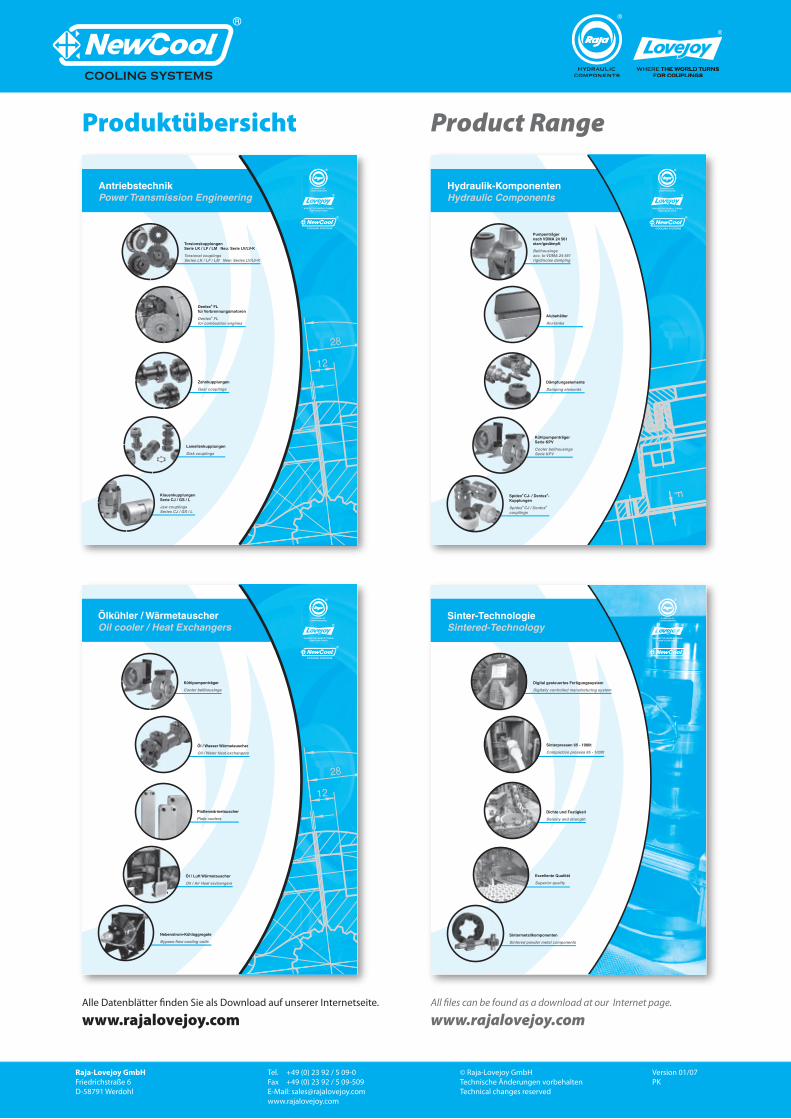
Produktübersicht
Alle Datenblätter finden Sie als Download auf unserer Internetseite.
www.rajalovejoy.com
Product Range
All files can be found as a download at our Internet page.
www.rajalovejoy.com
Raja-Lovejoy GmbHFriedrichstraße 6D-58791 Werdohl
Tel. +49 (0) 23 92 / 5 09-0Fax +49 (0) 23 92 / 5 09-509E-Mail: [email protected]
© Raja-Lovejoy GmbH Technische Änderungen vorbehaltenTechnical changes reserved
Version 01/07 PK