jpeg decompression algorithm implementation using hls
DESCRIPTION
Jpeg decompression algorithm implementation using HLS. Final part A presentation Winter 2013-14. Performed by: Dor Kasif, Or Flisher Instructor: Rolf Hilgendorf. JPEG - most widely used standard for compression of digital images. Done by software , takes a lot of CPU resources. The solution - PowerPoint PPT PresentationTRANSCRIPT
Performed by: Dor Kasif, Or FlisherInstructor: Rolf Hilgendorf
Jpeg decompression algorithm implementation using HLS
Final part A presentationWinter 2013-14
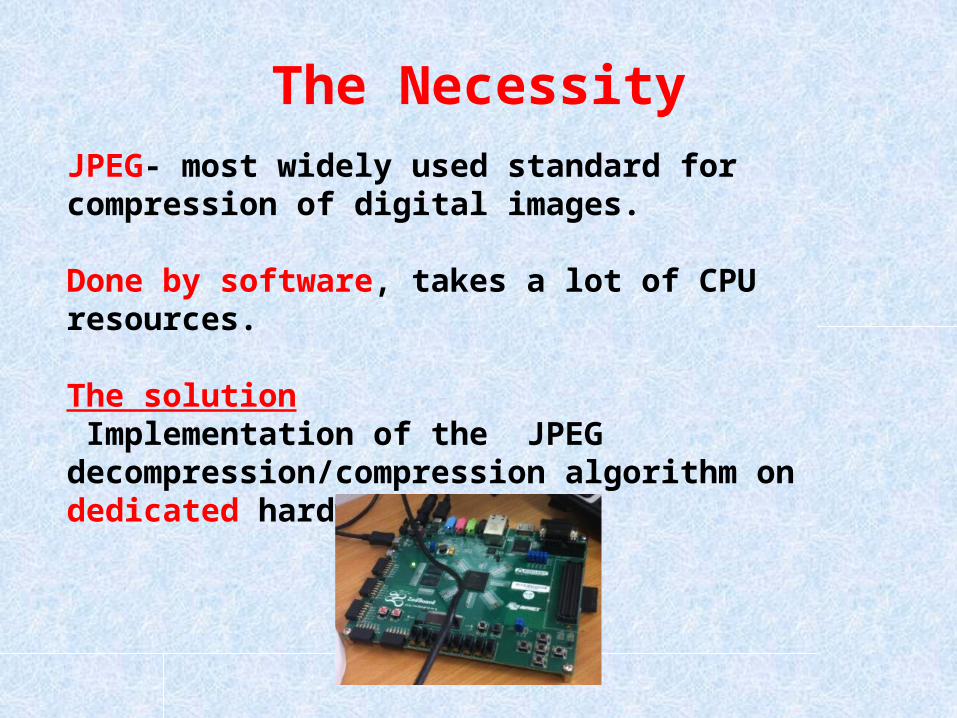
The NecessityJPEG- most widely used standard for compression of digital images.
Done by software, takes a lot of CPU resources.
The solution Implementation of the JPEG decompression/compression algorithm on dedicated hardware.
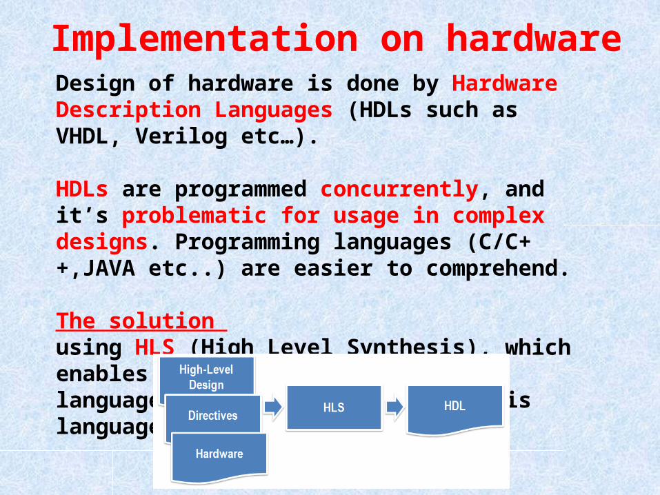
Implementation on hardwareDesign of hardware is done by Hardware Description Languages (HDLs such as VHDL, Verilog etc…).
HDLs are programmed concurrently, and it’s problematic for usage in complex designs. Programming languages (C/C++,JAVA etc..) are easier to comprehend.
The solution using HLS (High Level Synthesis), which enables the use of a programming language as the design and synthesis language.
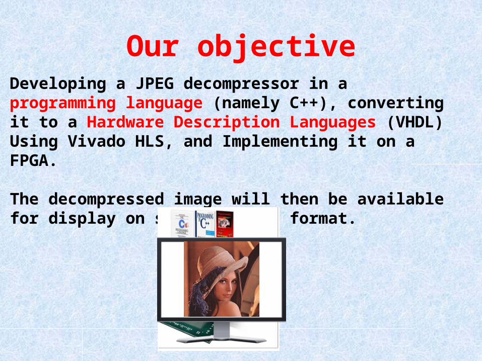
Our objectiveDeveloping a JPEG decompressor in a programming language (namely C++), converting it to a Hardware Description Languages (VHDL) Using Vivado HLS, and Implementing it on a FPGA.
The decompressed image will then be available for display on screen in RGB format.
Project Goals• Implementing the Jpeg decompression algorithm on a FPGA Using HLS.
• Displaying the decompressed image in a RGB format on screen.
• Optimizing the implementation to reach the optimal performances possible within the performance envelope of the FPGA.
• Compare the software decompressed picture to the hardware decompressed picture in terms of Structural Similarity Index Metric (SSIM) .
The VIVADO HLS
• Allow us to design hardware using a programing language, which is much more easy to work and design with.
• When using a programing language which is inherently serial in nature to design hardware which is inherently concurrent, we can’t use the already well known programming paradigms, so we will need to combine several disciplines.
• Those modifications include replacing non synthesizable commands and changes to reduce usage of system resources and optimizing overall system performance.

The VIVADO HLS types • In software, there are numerous types for a Variable : Integer,Char,Float, etc.
• A major disadvantage is being unable to access parts of the variable, like bits. Bitwise operations are enabled with programming language but not on a scope appropriate to hardware design. Moreover when designing hardware, system resources are valuable (i.e. board area, wiring etc.) so for some variable representations we’ll need to control the amount of memory allocated for the variable.
• The VIVADO HLS presents new types: ap_int<>, ap_uint<>,ap_fixed<><> etc.
• Those new types Not only allow us to determine the memory used but also grants us access to every part of the memory itself and in every scope desired (such as a single bit).
• For example: a Variable with only two options: “0” (“no”) and “1” (“yes”).• In C/C++: we can use Char , which takes a byte (8 bits) of memory. • In VIVADO HLS : ap_uint<1> - takes 1 bit of memory.
The VIVADO HLS functions • with The VIVADO HLS types we can use some new and helpful functions:
For example we used:
• Variable.range- access to certain bits of the Variable
• Variable.set-set a certain bit of the Variable to the value “1”.

Our progress
Progress until midterm presentation
• Acquired a C++ encoding/decoding algorithm and modified it for our needs-removing the use of non-standard libraries, removing user interface , adjusting the algorithm to process a single color channel etc.
• Developing auxiliary Matlab scripts for handling the images and SSIM computation.
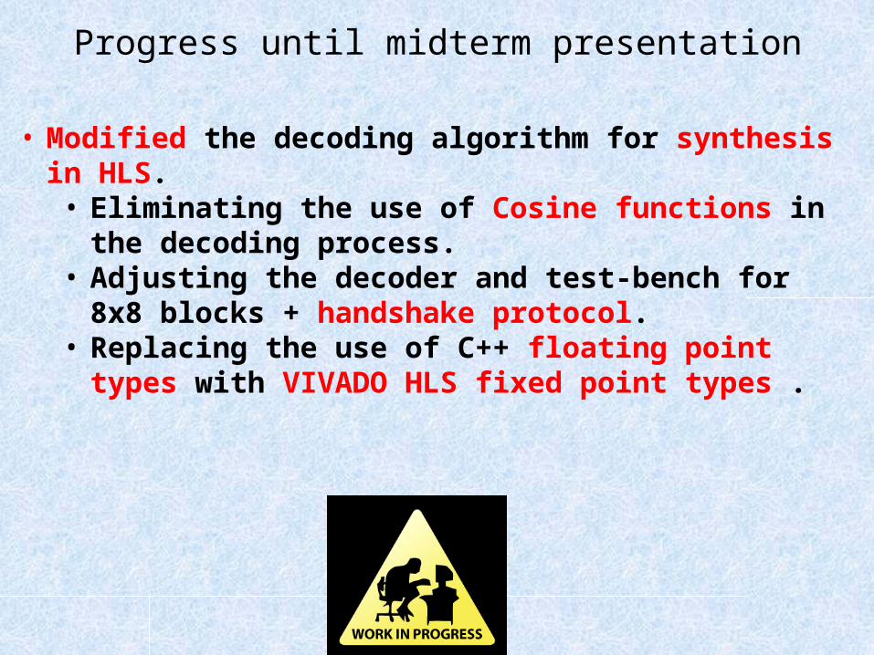
Progress until midterm presentation
• Modified the decoding algorithm for synthesis in HLS.• Eliminating the use of Cosine functions in the decoding
process.• Adjusting the decoder and test-bench for 8x8 blocks +
handshake protocol. • Replacing the use of C++ floating point types with VIVADO
HLS fixed point types .
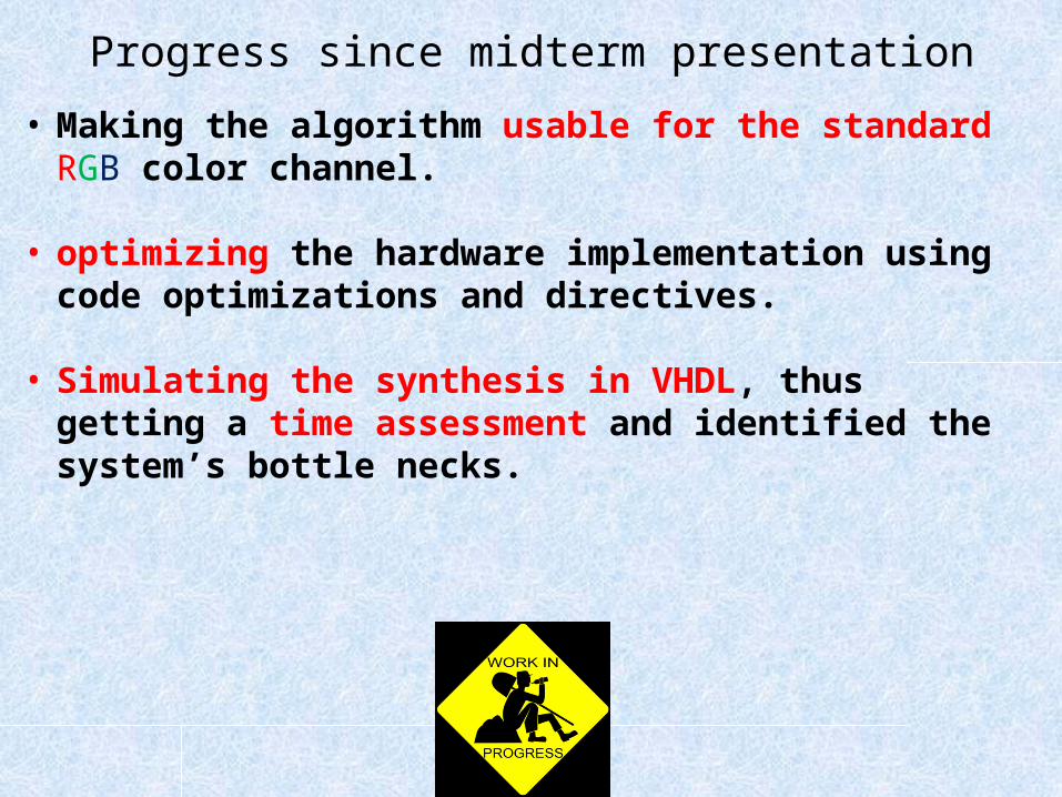
Progress since midterm presentation• Making the algorithm usable for the standard RGB color channel.
• optimizing the hardware implementation using code optimizations and directives.
• Simulating the synthesis in VHDL, thus getting a time assessment and identified the system’s bottle necks.

Implementing the encoding/decoding process
JPEG-DECOMPRESSORModule
(convert from C++ to VHDL using HLS)
27 bits
8x8 decompressed block
Encodedpicture
Hand shake protocol
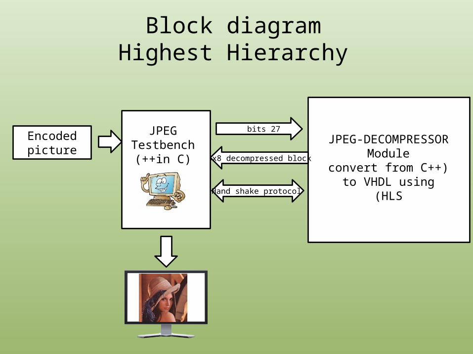
Block diagramHighest Hierarchy
JPEGTestbench
(in C)++

• We use the test bench file ,which inputs the encoded image stream of bits into the module file, aka the decoder.
• The test bench is sending a stream of 27 bits to the module each time.• The maximum code length of the AC/DC Huffman tables is 27 bits.
• The module constructs a full sub matrix block of size 8x8.
• The module will announce the completion of the 8x8 sub matrix through a handshake procedure.
• The image will then be ready for display on screen in RGB format.
Block diagramHighest Hierarchy

Lets See What's Under The Hood
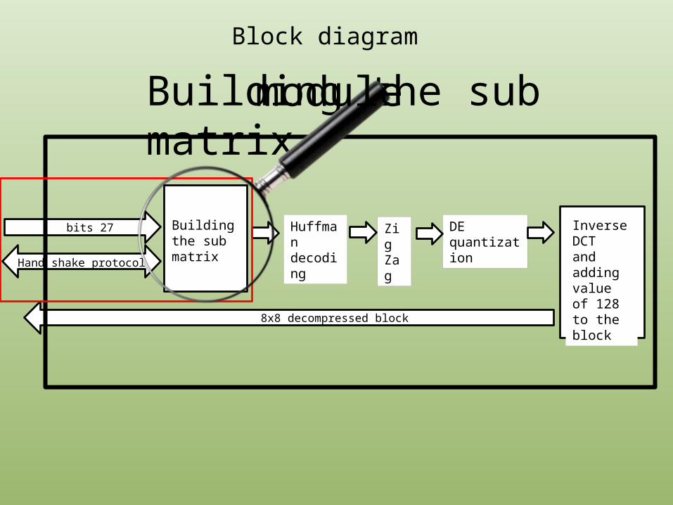
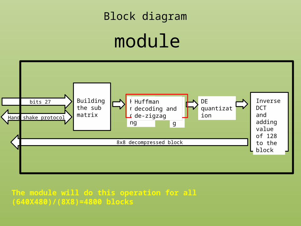
Huffmandecoding
27 bits DE quantization
Inverse DCTand adding value of 128 to the block 8x8 decompressed block
Hand shake protocol
Building the sub matrix
Zig Zag
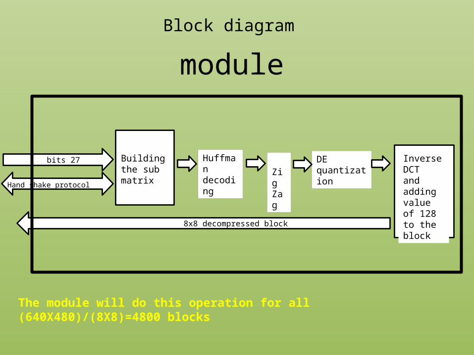
Block diagram
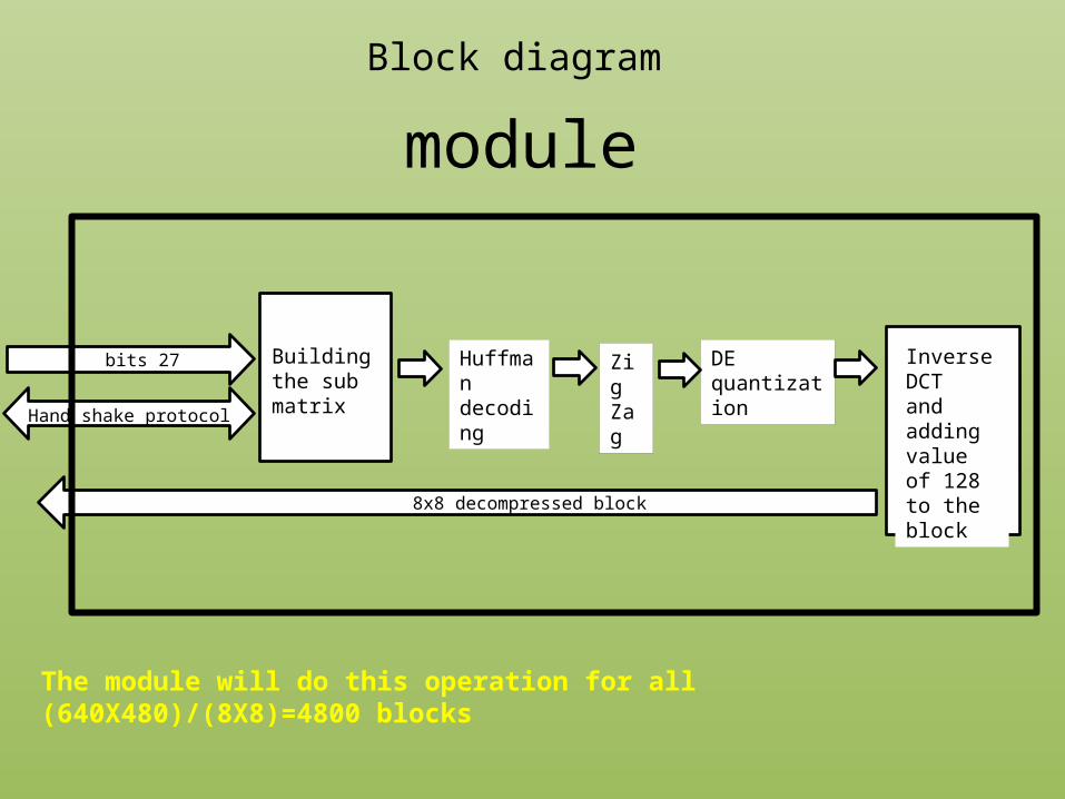
The module will do this operation for all (640X480)/(8X8)=4800 blocks
module
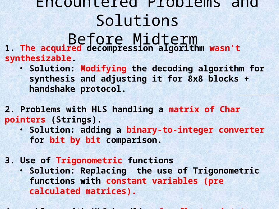
1. The acquired decompression algorithm wasn't synthesizable.• Solution: Modifying the decoding algorithm for synthesis and
adjusting it for 8x8 blocks + handshake protocol.
2. Problems with HLS handling a matrix of Char pointers (Strings).• Solution: adding a binary-to-integer converter for bit by bit
comparison.
3. Use of Trigonometric functions • Solution: Replacing the use of Trigonometric functions with constant
variables (pre calculated matrices).
4. problems with HLS handling C++ float point type and the multiplication of them.
• Solution: replacing the use of C++ fixed point types with VIVADO HLS fixed point types.
Encountered Problems and SolutionsBefore Midterm
Huffmandecoding
27 bits DE quantization
Inverse DCTand adding value of 128 to the block 8x8 decompressed block
Hand shake protocol
Building the sub matrix
Zig Zag
Block diagram
Building the sub matrix module
Block diagram
Building the sub matrix
Buffer(3*27bit size)
getACvalue getDCvalue
For D
C co
eff
Buffer has less then 27 bits
Hand shake protocol
the complete matrix
Char to int
For A
C co
eff
sub matrixbuffer
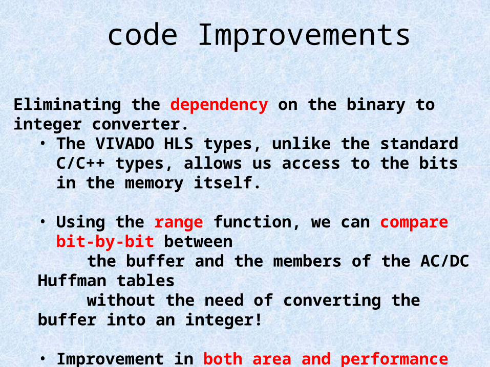
Eliminating the dependency on the binary to integer converter.• The VIVADO HLS types, unlike the standard C/C++ types, allows
us access to the bits in the memory itself.
• Using the range function, we can compare bit-by-bit between
the buffer and the members of the AC/DC Huffman tables without the need of converting the buffer into an integer!
• Improvement in both area and performance (no need for the converter module) .
code Improvements
Block diagram
Building the sub matrix
Buffer(3*27bit size)
getACvalue getDCvalue
For D
C co
eff
Buffer has less then 27 bits
Hand shake protocol
the complete matrix
Char to int
For A
C co
eff
sub matrixbuffer
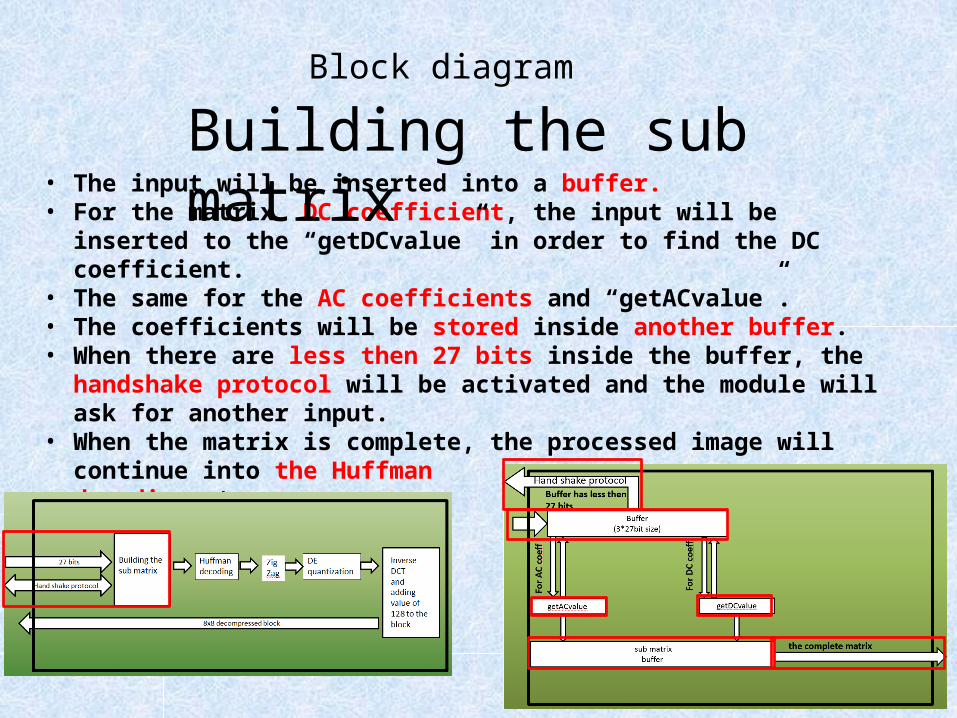
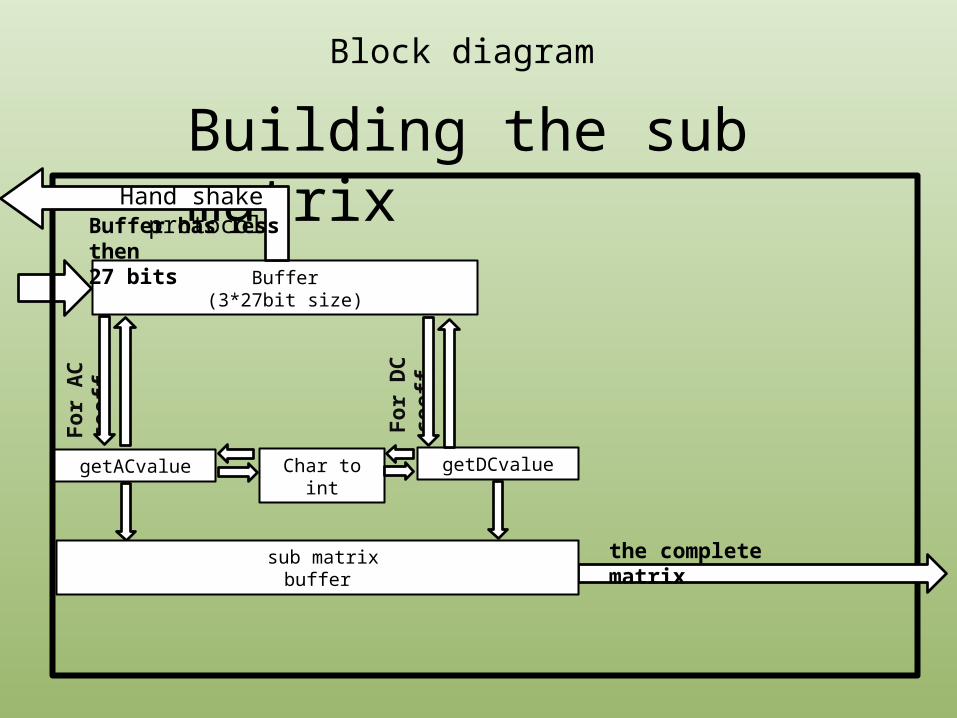
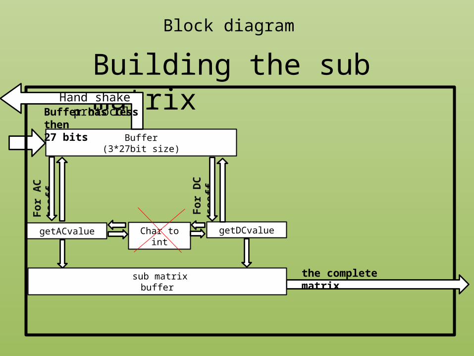
• The input will be inserted into a buffer.• For the matrix DC coefficient, the input will be inserted to the “getDCvalue” in
order to find the DC coefficient.• The same for the AC coefficients and “getACvalue”.• The coefficients will be stored inside another buffer.• When there are less then 27 bits inside the buffer, the handshake protocol will be
activated and the module will ask for another input.• When the matrix is complete, the processed image will continue into the Huffman
decoding stage.
Block diagramBuilding the sub matrix
Huffmandecoding
27 bits DE quantization
Inverse DCTand adding value of 128 to the block 8x8 decompressed block
Hand shake protocol
Building the sub matrix
Zig Zag
Block diagram
The module will do this operation for all (640X480)/(8X8)=4800 blocks
module
combining the de-zigzag and Huffman decoding operations and Improving them• The de-zigzag operation may take a lot of time (storing in the
memory each member in it’s place in the matrix). Also, we know that as part of the JPEG decoding algorithm, many of the matrix’ members will be zeroes.
• First, we zeroed the matrix in the beginning of our decoding operation (to avoid data dependencies). We also converted the de-zigzag operation to a MUX like code and integrated it as part of the Huffman decoding operation. The MUX usage costs us in area but improved performances.
code Improvements
Huffmandecoding
27 bits DE quantization
Inverse DCTand adding value of 128 to the block 8x8 decompressed block
Hand shake protocol
Building the sub matrix
Zig Zag
Block diagram
The module will do this operation for all (640X480)/(8X8)=4800 blocks
module
Huffman decoding and de-zigzag
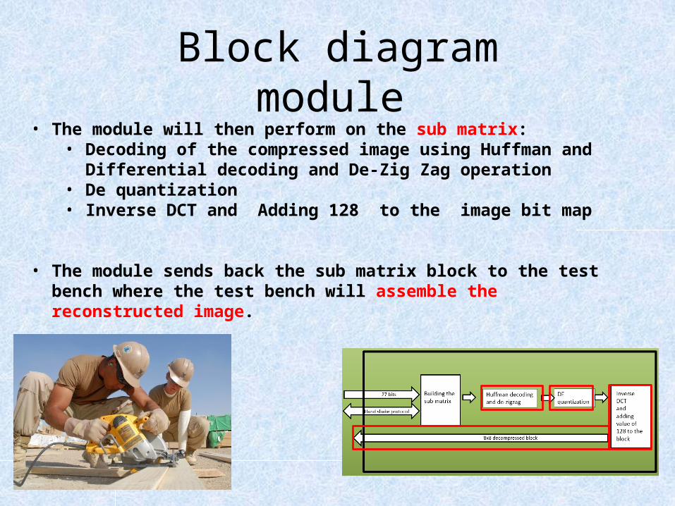
• The module will then perform on the sub matrix:• Decoding of the compressed image using Huffman and Differential decoding
and De-Zig Zag operation • De quantization• Inverse DCT and Adding 128 to the image bit map
• The module sends back the sub matrix block to the test bench where the test bench will assemble the reconstructed image.
Block diagrammodule
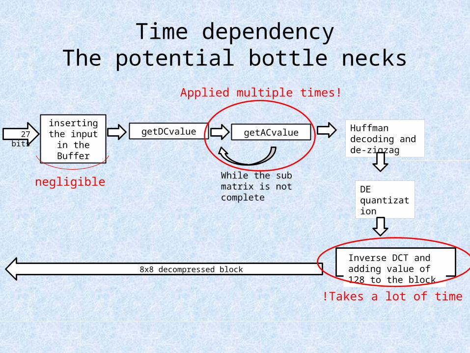
Time dependencyThe potential bottle necks
27 bits
DE quantization
Inverse DCT and adding value of 128 to the block
While the sub matrix is not complete
inserting the input in the
BuffergetACvaluegetDCvalue Huffman decoding
and de-zigzag
8x8 decompressed block
negligible
Takes a lot of time!
Applied multiple times!

Improvements
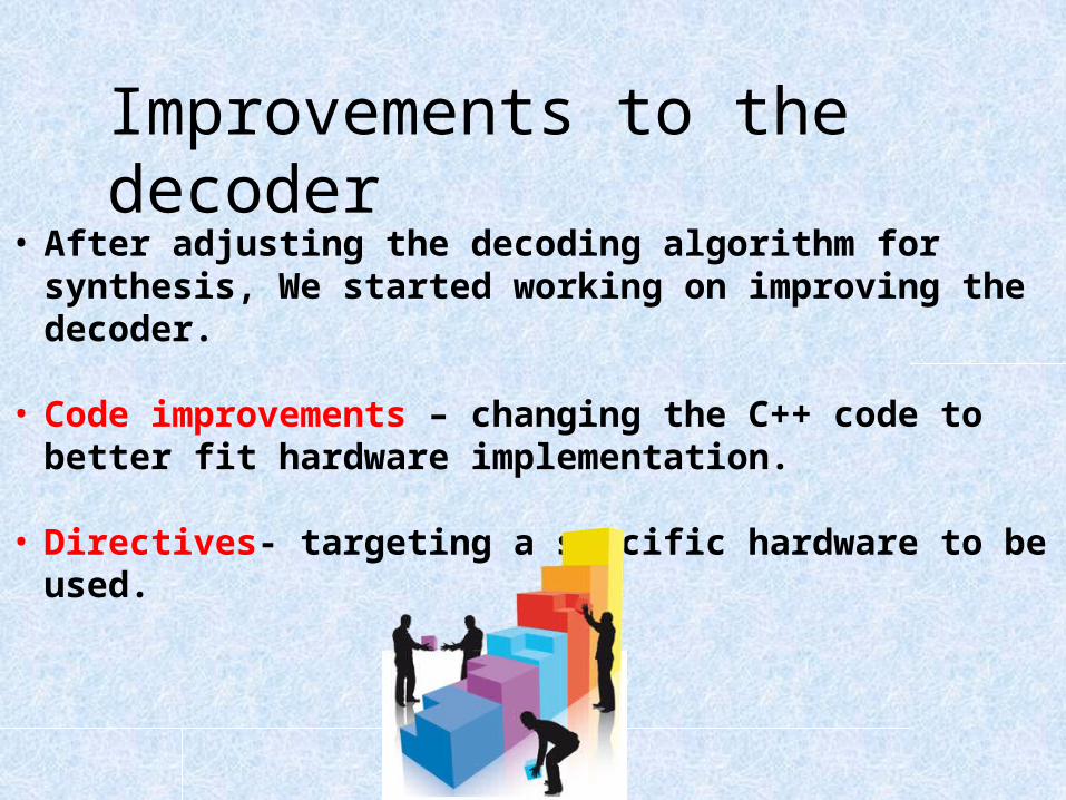
• After adjusting the decoding algorithm for synthesis, We started working on improving the decoder.
• Code improvements – changing the C++ code to better fit hardware implementation.
• Directives- targeting a specific hardware to be used.
Improvements to the decoder
VIVADO HLS Directives • In VIVADO HLS, when synthesizing a module, the VIVADO tries to create
the best hardware it can in terms of speed and resources utilization, But it has some limitations.
• At first, improvements and changes must be applied to the C++ code to better fit hardware implementation. This method is also limited as it doesn’t allow us to decide the specific hardware to be used.
• Using the directives, we are allowed to influence the hardware generating process and improve it even more, by targeting a certain resource to be used and adding hardware for improvements in terms of speed.

Directives we used • Pipeline- allow us to pipeline a certain hardware, pipelining the internal loops and
unrolling them for parallel calculation. • The unrolling process and pipelining will cause more resources utilization, but
may increase performances
• Array partition- partitioning the memory into small elements, thus allowing us access different memory elements at parallel.
• Loop_trip_count- sometimes loops are variable dependent, meaning that the number of loops depends on our input. In that case, we can’t have a measuring of the operation time. In order to have some boundaries to estimate our operation time, using this directory we can decide an upper and lower bound for our number of loops.• At later times, when enough improvements has been made, this Directive will
become obsolete.
Limiting memory area • By using VIVADO HLS types, we are able to restrict the memory
area each variable takes, thus reducing area utilization.
code Improvements

Time dependencyThe potential bottle necks
27 bits
DE quantization
Inverse DCT and adding value of 128 to the block
While the sub matrix is not complete
inserting the input in the
BuffergetACvaluegetDCvalue Huffman decoding
and de-zigzag
8x8 decompressed block
negligible
Takes a lot of time!
Applied multiple times!
Replacing the functions handling the buffer to VIVADO HLS functions
• In the past, in order to handle the bits stored in the buffer (inserting the input or shifting them) we applied a FIFO like algorithm, inserting or shifting the input bit by bit- takes time and resources.
• Using the VIVADO HLS function range, we are able to replace this algorithm with a simple parallel insertion, greatly improving our time and resource .
code ImprovementsInput_to_buffer and shift_bit
Improving the exponentiation function.
• In our code, there are several places where we need to calculate 2^i where i is the order of the digit, but the exponentiation function isn’t synthesizable.
• At first, we calculated it using a loop: for(j=0;j<i;j++) p=2*p; -Took time (about i clock cycles) and hardware.• In binary, the number calculated by 2^i is a zeroed number with a
“1” in the i-th bit• For example: 2^2=100, 2^4=10000…
• we can use the set function to set the i-th bit of a zeroed variable to “1” –almost no hardware and a lot less time (1 clock cycle).
code ImprovementsgetDCvalue and getACvalue
Directive improvements
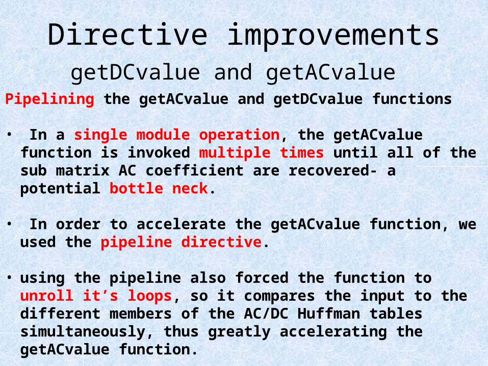
Pipelining the getACvalue and getDCvalue functions
• In a single module operation, the getACvalue function is invoked multiple times until all of the sub matrix AC coefficient are recovered- a potential bottle neck.
• In order to accelerate the getACvalue function, we used the pipeline directive.
• using the pipeline also forced the function to unroll it’s loops, so it compares the input to the different members of the AC/DC Huffman tables simultaneously, thus greatly accelerating the getACvalue function.
• We used the same method on the getDCvalue (also part of our bottle neck).
getDCvalue and getACvalue

Directive improvements
Pipelining loops in the DCT function• The inverse DCT function is composed of computing:
Where dct_coeff is a constant matrix, and F[u][v] is our sub matrix before DCT.
• Because the dct_coeff is a fixed point type, multiplication of its members is a huge bottle neck to our design.
• We applied the pipeline directive on the loop right before the most inner loop, also enforcing unrolling of the most inner loop.
• Using this, we can make 8 multiplications at once, greatly accelerating our function, but in cost of much more resource utilization.
DCT FUNCTION
𝑓 [𝑥] [𝑦 ]= ∑𝑢 ,𝑣=0
𝑢 ,𝑣=7
¿ ¿
Directive improvements
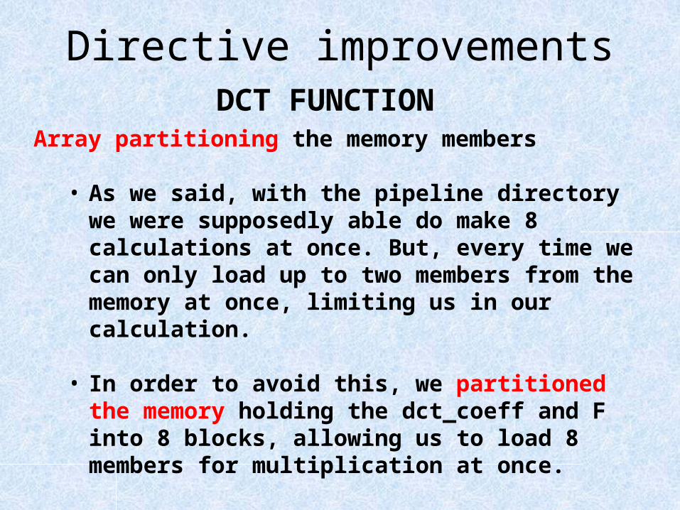
Array partitioning the memory members
• As we said, with the pipeline directory we were supposedly able do make 8 calculations at once. But, every time we can only load up to two members from the memory at once, limiting us in our calculation.
• In order to avoid this, we partitioned the memory holding the dct_coeff and F into 8 blocks, allowing us to load 8 members for multiplication at once.
DCT FUNCTION
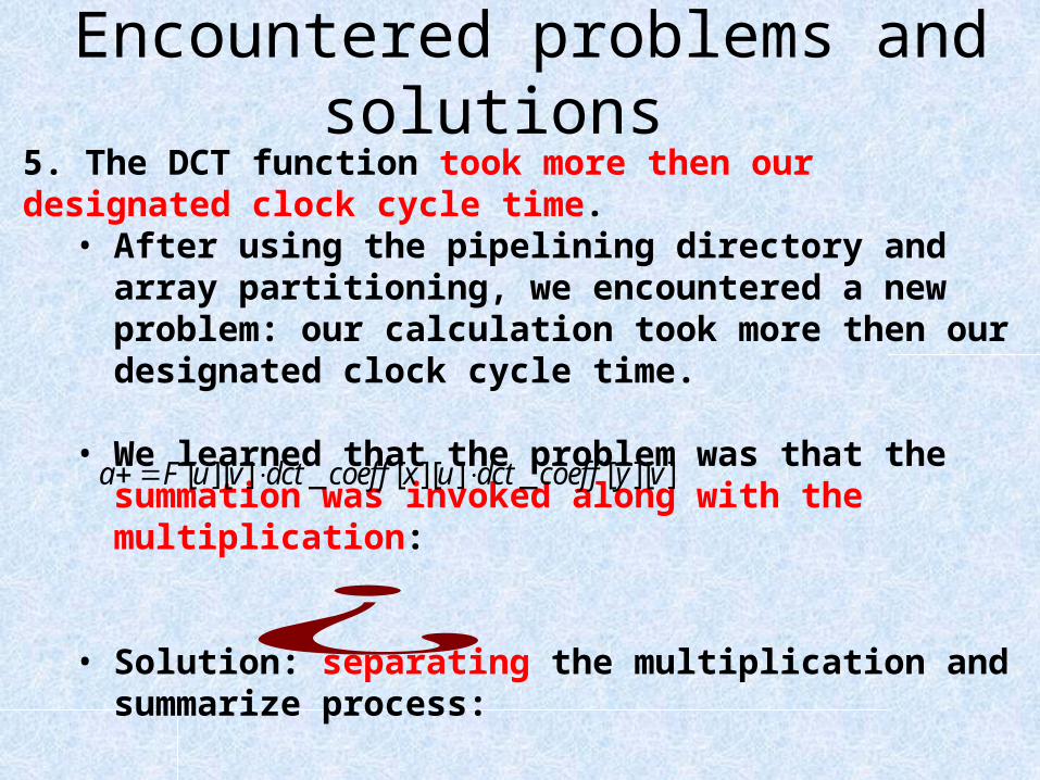
5. The DCT function took more then our designated clock cycle time. • After using the pipelining directory and array partitioning, we
encountered a new problem: our calculation took more then our designated clock cycle time.
• We learned that the problem was that the summation was invoked along with the multiplication:
• Solution: separating the multiplication and summarize process:
Encountered problems and solutions
[ ][ ] _ [ ][ ] _ [ ][ ]a F u v dct coeff x u dct coeff y v
¿
Directories improvements
Pipelining loops in the quantization function• Same as DCT
Array partitioning the memory members• Same as DCT
Quantisize FUNCTION
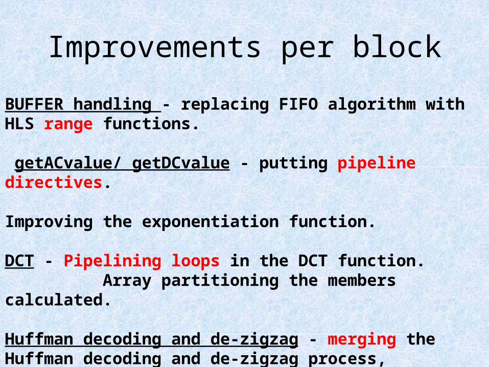
Improvements per block
BUFFER handling - replacing FIFO algorithm with HLS range functions.
getACvalue/ getDCvalue - putting pipeline directives. Improving the exponentiation function.
DCT - Pipelining loops in the DCT function. Array partitioning the members calculated.
Huffman decoding and de-zigzag - merging the Huffman decoding and de-zigzag process, resetting the quantization matrix and transforming the de-zigzag process to a mux.
DE-Quanitisize function - same as DCT.
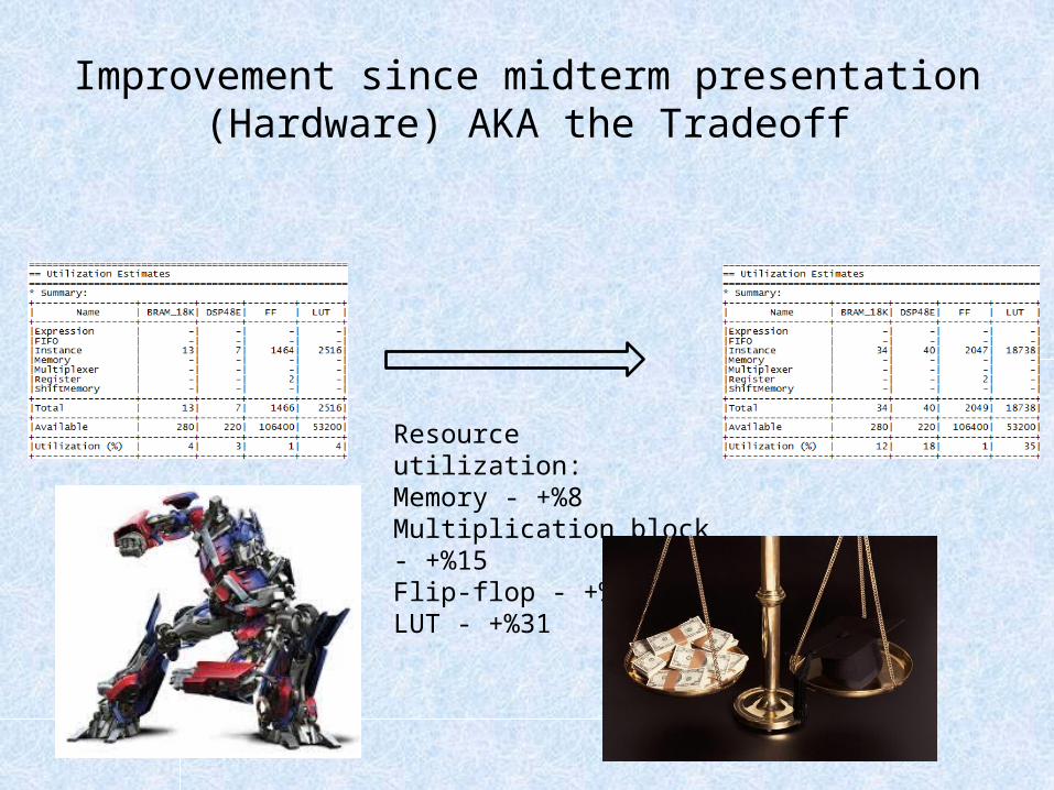
Improvement since midterm presentation (Hardware) AKA the Tradeoff
Resource utilization:Memory - +%8Multiplication block - +%15Flip-flop - +%0LUT - +%31
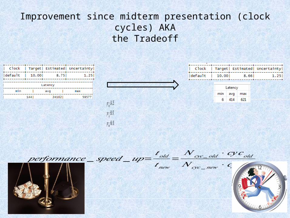
Improvement since midterm presentation (clock cycles) AKAthe Tradeoff
𝑝𝑒𝑟𝑓𝑜𝑟𝑚𝑎𝑛𝑐𝑒 _ 𝑠𝑝𝑒𝑒𝑑 _𝑢𝑝=𝑡𝑜𝑙𝑑𝑡𝑛𝑒𝑤
=𝑁𝑐𝑦𝑐 _ 𝑜𝑙𝑑⋅ 𝑐𝑦𝑐𝑜𝑙𝑑
𝑁 𝑐𝑦𝑐 _𝑛𝑒𝑤 ⋅ 𝑐𝑦𝑐𝑛𝑒𝑤
𝑝𝑒𝑟min=24 .25𝑝𝑒𝑟𝑎𝑣𝑔=58 .97𝑝𝑒𝑟max=96 .93

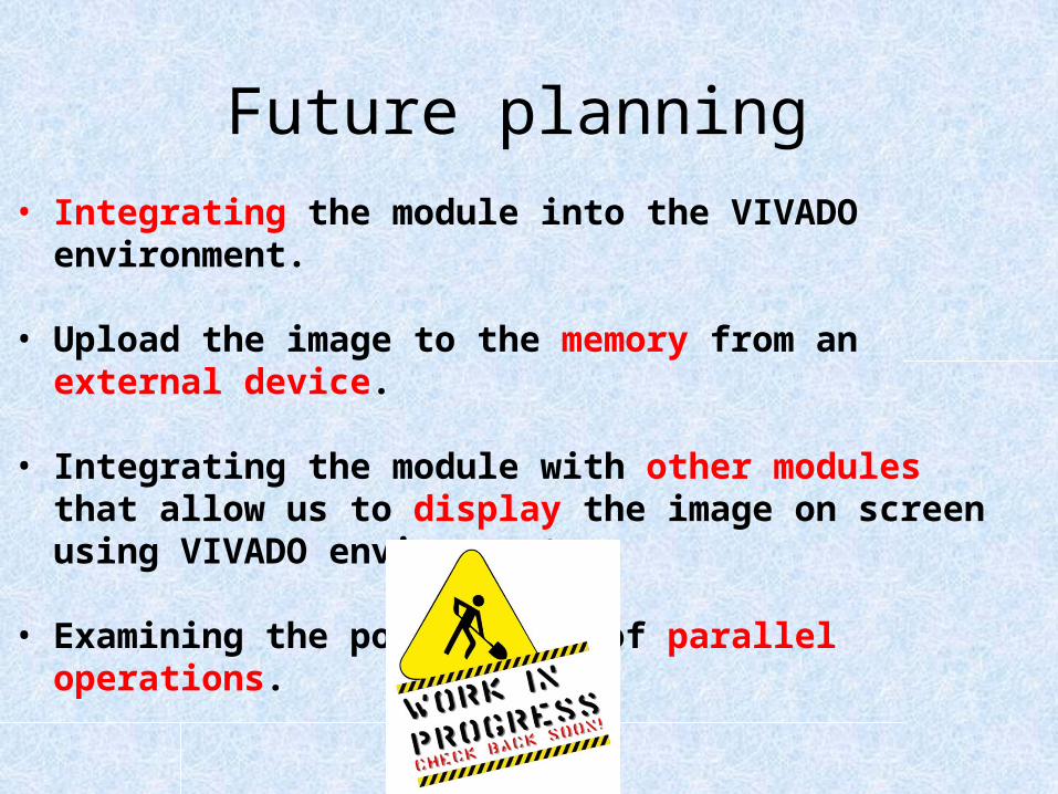
Future planning• Integrating the module into the VIVADO environment.
• Upload the image to the memory from an external device.
• Integrating the module with other modules that allow us to display the image on screen using VIVADO environment.
• Examining the possibility of parallel operations.
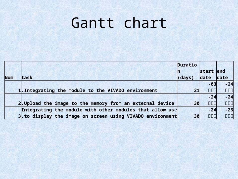
Gantt chart
Num taskDuration
(days)start date
end date
1 Integrating the module to the VIVADO environment. 21 אפר-03 אפר-242 Upload the image to the memory from an external device. 30 אפר-24 מאי-24
3eIntegrating the module with other modules that allow us to display
the image on screen using VIVADO environment. 30 מאי-24 יונ-23
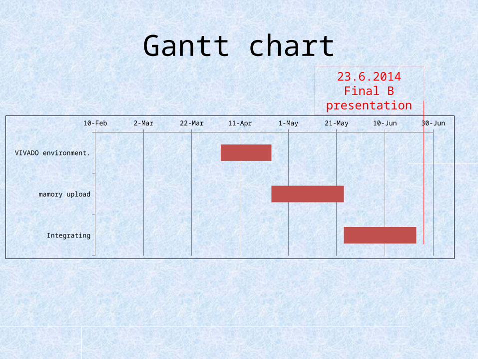
Gantt chart23.6.2014
Final B presentation
VIVADO environment.
mamory upload
Integrating
10-Feb 2-Mar 22-Mar 11-Apr 1-May 21-May 10-Jun 30-Jun

Resources http://www.cs.northwestern.edu/~agupta/_projects/image_processing/web/JPEGEncoding/report.html-source for the encoding/decoding codehttp://en.wikipedia.org/wiki/JPEG-jpeg Wikipedia entryhttp://sipl.technion.ac.il/-the technion signal and image processing lab-experiment 3www.stanford.edu/class/ee398a/handouts/lectures/08-JPEG.pdf-Stanford university , department of electrical engineering explanation of the Jpeg format.Essay- The JPEG Still Picture Compression Standard-by Gregory K.Wallace and co.-explanation of the Jpeg format.https://ece.uwaterloo.ca/~z70wang/research/ssim/Howard Hughes Medical Institute, and Laboratory,. By Z. Wang, A. C. Bovik, H. R. Sheikh,and E. P. Simoncelli-Matlab script for SSIM computation.Essay-Image Quality Assessment Techniques pn Spatial Domain-by C.Sasi varnan and co.