jpringfield armory vibl, · springfield armory procedures, and then sectioned to permit measurement...
TRANSCRIPT
" — JPRINGFIELD ARMORY ViBl,
RESEARCH AND DEVELOPMENT
TECHNICAL LIBRARY AJ11JX Report; SA-TR18-1070
Date: 12 February 1960
Report Title: A Determination of the Distribution of Chromium Plate in the Bores of Small Arms Barrels.
Author; /ft<rf *&*&£. Approved: /V%<^^^^>^" M. 8. Spwak ^ c.-fl. FC/ttawthorne Chem Engr Chief, Res and Dev Div
FILE DOl E
SPRINGFIELD, MASSACHUSETTS
Report: SA-TR18-1070
Date: 12 February 1960
Report Title: A Determination of the Distribution of Chromium Plate In the Bores of Small Arms Barrels.
Author: Approved: M.S. SP/VAK Chem Engr.
r. F/RAWTHORNE lef, Res and Dev Dlv
Project Title: Engineering for the Ord Project: Application of Chromium Plating of Small Arms Barrel Bores.
DA Project:
Industrial Preparedness Measure
None
Preparing Agency: Springfield Armory Springfield, Mass.
This report has no distribution limitations. Initial distribution of this report has been made in accordance with the attached distribution list. Requests for add- itional copies of this report will be made to ASTIA.
REPORT SA-TR18-1070
ABSTRACT
AD Accession UNCLASSIFIED
Springfield Armory, Springfield, Mass. A DETERMINATION OF THE DISTRIBUTION OF CHROMIUM PLATE 1. IN THE BORES OF SMALL ARMS BARRELS, M. S. Spivak, Tech Rpt SA-TR18-1070, 12 Feb 60, 13 pp incl illus, Ord Proj - Industrial Preparedness Measure. 2.
Unclassified Report. Nonlimited distribution. 3.
An investigation was made to develop a method for the determination of the distribution of chromium plate in the bores of small arms barrels. Barrels of various calibers were chromium plated according to Springfield Armory procedures. These barrels were then sectioned and the chromium thickness was measured at the lands and grooves. Graphs were plotted of groove chromium thickness versus land chromium thickness for the various barrels. Ratios of land-to-groove chromium plating thicknesses have been established for calibers 0.30, 0.45, 0.50, 20mm, and 30mm barrel bores. These ratios apply to barrel bores which have been chromium plated under existing plating procedures used at Springfield Armory. Procedures are described and results discussed.
Chromium Plating - Distribution
Plating, Chromium
Gun barrels - Plating
UNCLASSIFIED
FOR READER'S USE - DO NOT REMOVE
REPORT SA-TR18-1070
SUBJECT
A determination of the Distribution of Chromium Plate In the Bores of Small Arms Barrels.
OBJECT
To determine the ratio of chromium deposited on the lands to that deposited ', on the grooves in small arms barrels, thereby providing a means of calculating the chrome thickness on either segment when only one has been measured.
SUMMARY
1. Various caliber barrels were chrome plated according to existing Springfield Armory procedures, and then sectioned to permit measurement of chromium thickness at the lands and grooves. A graph of Groove Chromium Thickness VS Land Chromium Thickness for the various barrels was plotted, thereby permitting the determination of the land-to-groove ratio for each barrel tested.
2. Copper and steel anodes were used in the plating procedures.
-1-

REPORT SA-TR18-1070
-2-
REPORT SA-TR18-1070
1. INTRODUCTION
a. Existing methods employed at the Springfield Armory for inspection of barrel bores and gaging of chromium plating thickness depend on meas- urement of the bore diameter (at the lands) after the lands and grooves have been electropolished, and again, after they have been chrome- plated. One half of the differential in readings is accepted as being rep*1
resentatlve of the amount of chromium deposited In the bore. Chrom- ium thickness on the grooves is not measured. It has been found,how- ever, that groove information is highly desirable.
•
b. It was necessary to develop a method for determining the thickness of chromium deposited in the grooves without involving redesign of gages or modification of the plating procedure.
o. A possible method is the establishment of a ratio of groove-to-land thickness (providing that variations in plating procedure are taken in- to account) for each caliber barrel.
• 2. MATERIALS AND EQUIPMENT
a. Barrels;
Barrels of various sizes ranging from . 30 caliber to 30mm on the bore diameter.
» b. Plating;
(1) Generator (12 volt)
(2) Steel and Copper electrodes between 1/8 Inch and 3/8 inch diameter.
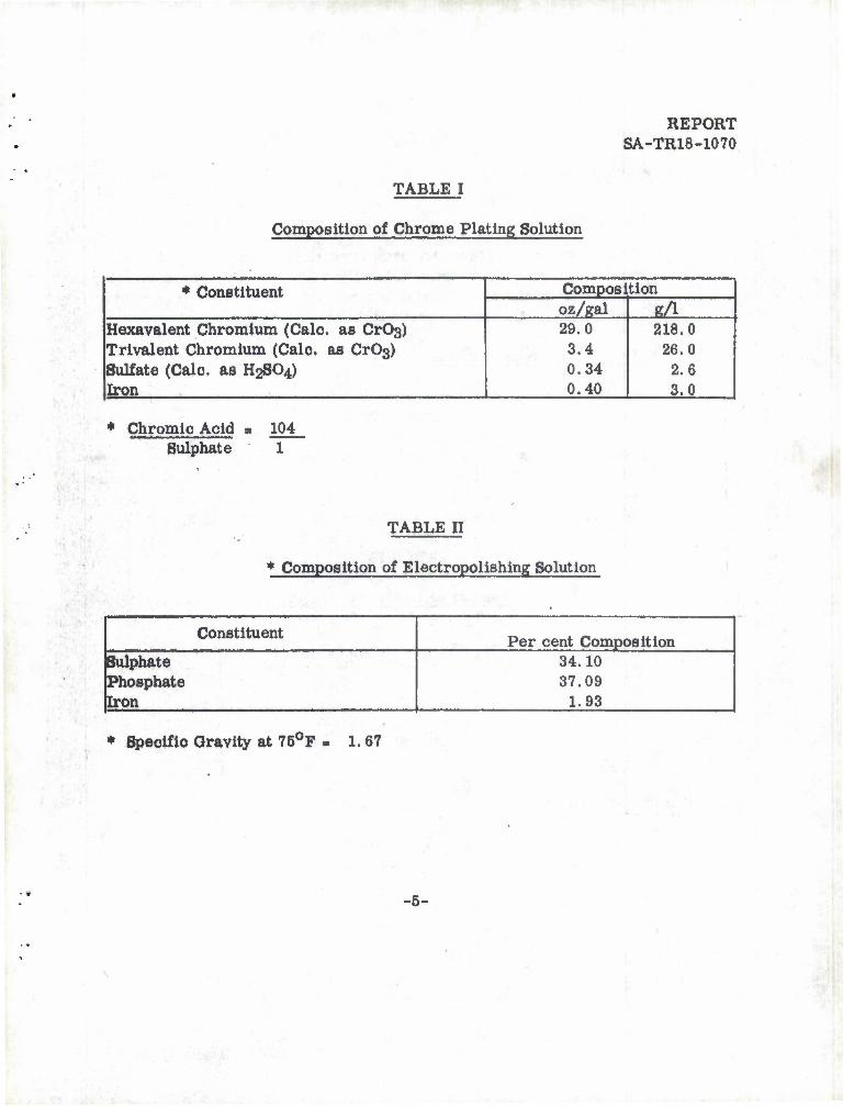
(3) Standard electropolishing and chromium plating solutions. See Tables I and U for compositions.
<
-3-
. REPORT SA-TR18-1070
MATERIALS AND EQUIPMENT - Continued
(4) Air gages, electropolishing and electroplating,for each caliber barrel.
3.
(5) Fixtures
c. Metallographic:
(1) Saw (metal cutting, automatic)
(2) Grinding Machine
(3) Abrasive papers of various grit size,
(4) Wax finishing wheel
(5) Lucite mounting material
(6) Mount compressor
(0 Metal etchant
(8) Mioroscope
PROCEDURE
a. Electropolishing and Plating
All barrels were electropolished, and plated in the standard solutions. (See Tables I and II). The amount of chromium deposited during electro-plating was approximately equal to the amount of steel removed during electropolishing. The barrels were gaged after each procedure. Gaging methods used were those currently practiced at the Springfield Armory.
-4-
REPORT SA-TR18-1070
TABLE I
Composition of Chrome Plating Solution
* Constituent Composition oz/gal g/1
Hexavalent Chromium (Calc. ae CrOs) Trivalent Chromium (Calo. as Cr03> Sulfate (Calo. as H2SO4) Iron
29.0 3.4 0.34 0.40
218.0 26.0 2.6 3.0
* Chromic Acid a 104 Sulphate
TABLE II
• Composition of Electropolishlng Solution
Bull
Constituent Per cent Composition phate
Phosphate Iron
34.10 37.09
1.93
* Speoific Gravity at 75°F - 1.67
-5-
REPORT SA-TR18-1070
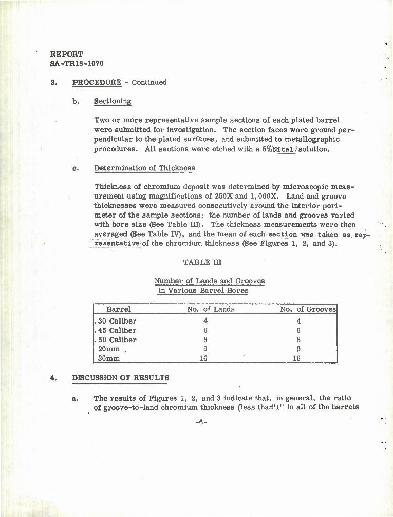
3. PROCEDURE - Continued
b. Sectioning
'
Two or more representative sample sections of each plated barrel were submitted for investigation. The section faces were ground per- pendicular to the plated surfaces, and submitted to metallographic procedures. All sections were etched with a 5%Nltal /solution.
Determination of Thickness
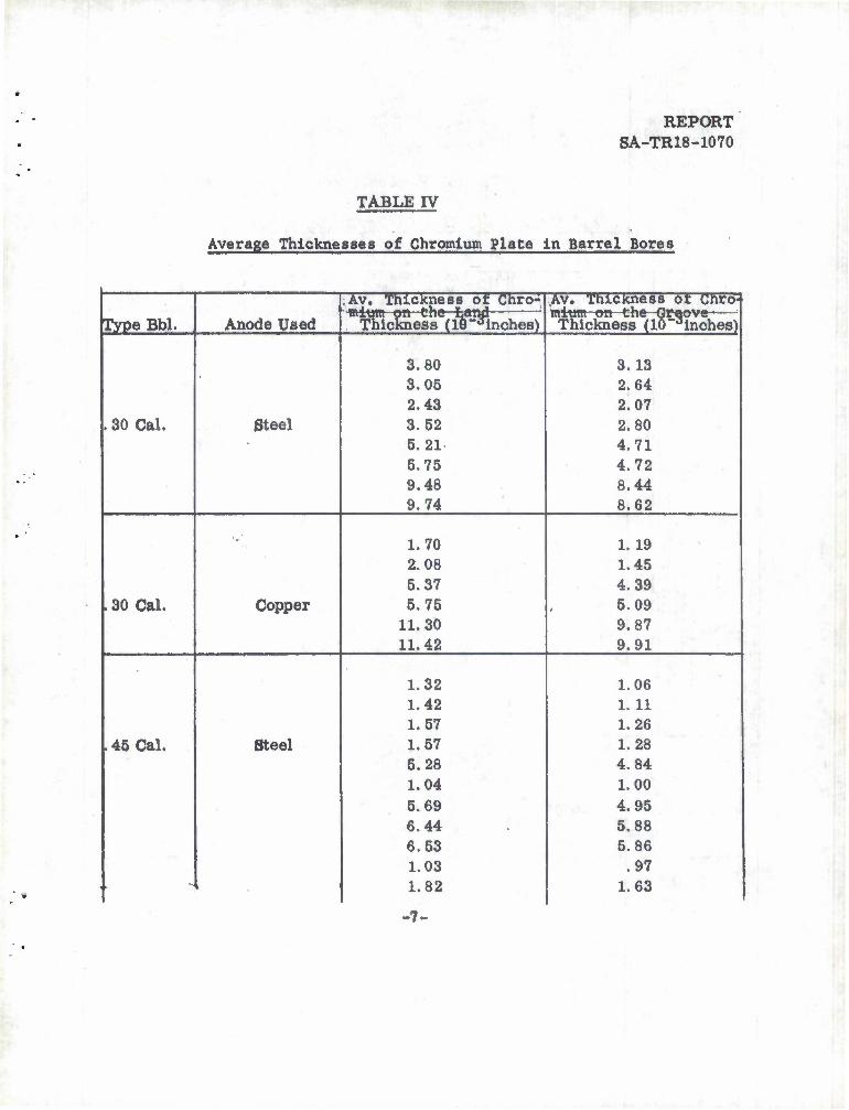
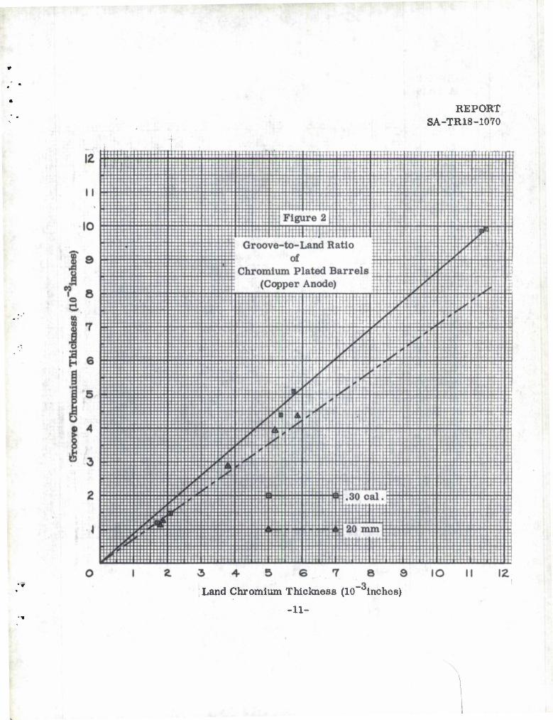
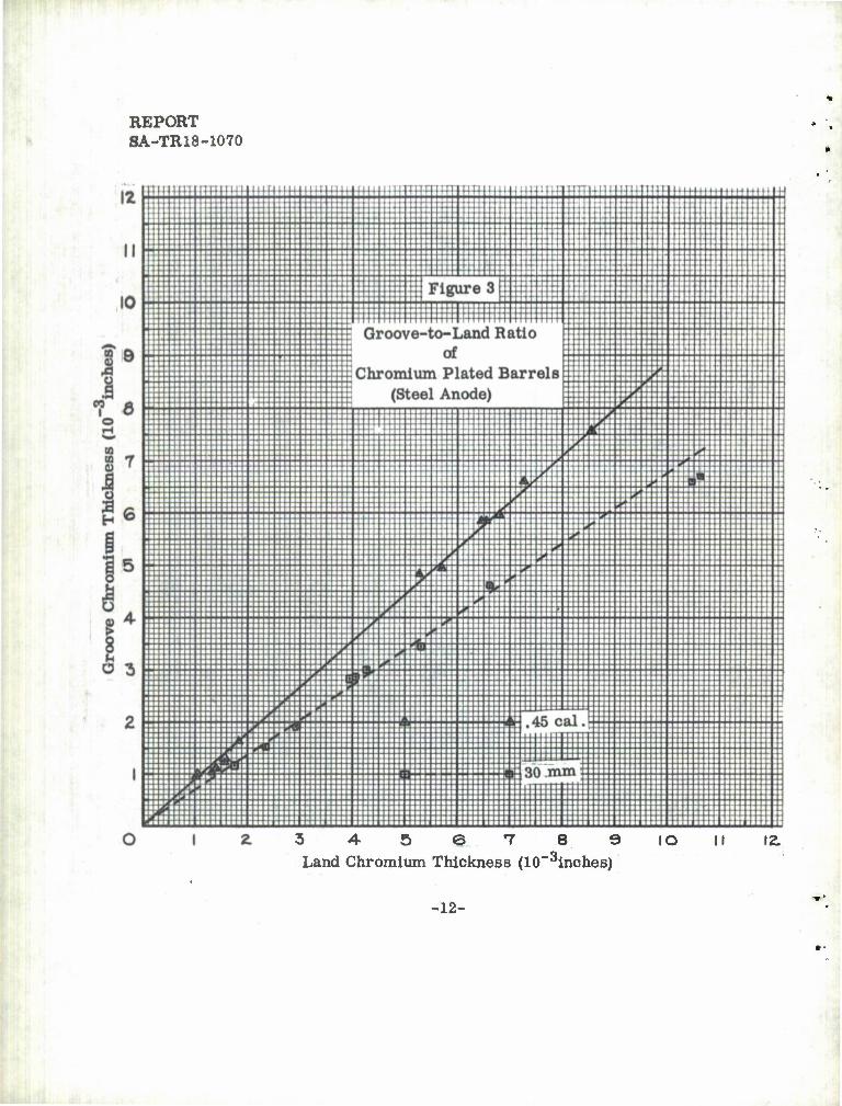
Thickness of chromium deposit was determined by microscopic meas- urement using magnifications of 250X and 1,000X. Land and groove thicknesses were measured consecutively around the interior peri- meter of the sample sections; the number of lands and grooves varied with bore size (See Table III). The thickness measurements were then averaged (See Table TV), and the mean of each section was taken as. rep- resentative,of the chromium thickness (See Figures 1, 2, and 3).
TABLE IE
Number of Lands and Grooves •
in Various Barrel Bores
Barrel No. of Lands No, of Grooves
.30 Caliber 4 4
. 45 Caliber 6 6
. 50 Caliber 8 8 20mm 9 9 30mm 16 16
4. DISCUSSION OF RESULTS
a. The results of Figures 1, 2, and 3 indicate that, in general, the ratio of groove-to-land chromium thickness (less thari'l" in all of the barrels
t
-6-
REPORT SA-TR18-1070
TABLE IV
•
Average Thicknesses of Chromium plate In Barrel Bores
Av. Thickness of Chro- Av. Thickness ot Chro- in i tjtn on c nft Or^ovc^— Thickness (10~3Inches) Type Bbl. Anode Used
niuffl on cne Lanp Thickness (18-,Jinches)
3.80 3.13 3.05 2.64 2.43 2.07
. 30 Cal. Steel 3.52 2.80 5.21 4.71 5.75 4.72 9.48 8.44 9.74 8.62
•-;( 1.70 1.19 2.08 1.45 5.37 4.39
. 30 Cal. Copper 5.75 5.09 11.30 9.87 11.42 9.91
1.32 1.06 1.42 1.11 1.57 1.26
.45 Cal. Steel 1.57 1.28 5.28 4.84 1.04 1.00 5.69 4.95 6.44 5.88 6.53 5.86 1.03 .97
1.63 . 1.82
-7-
REPORT SA-TR18-1070
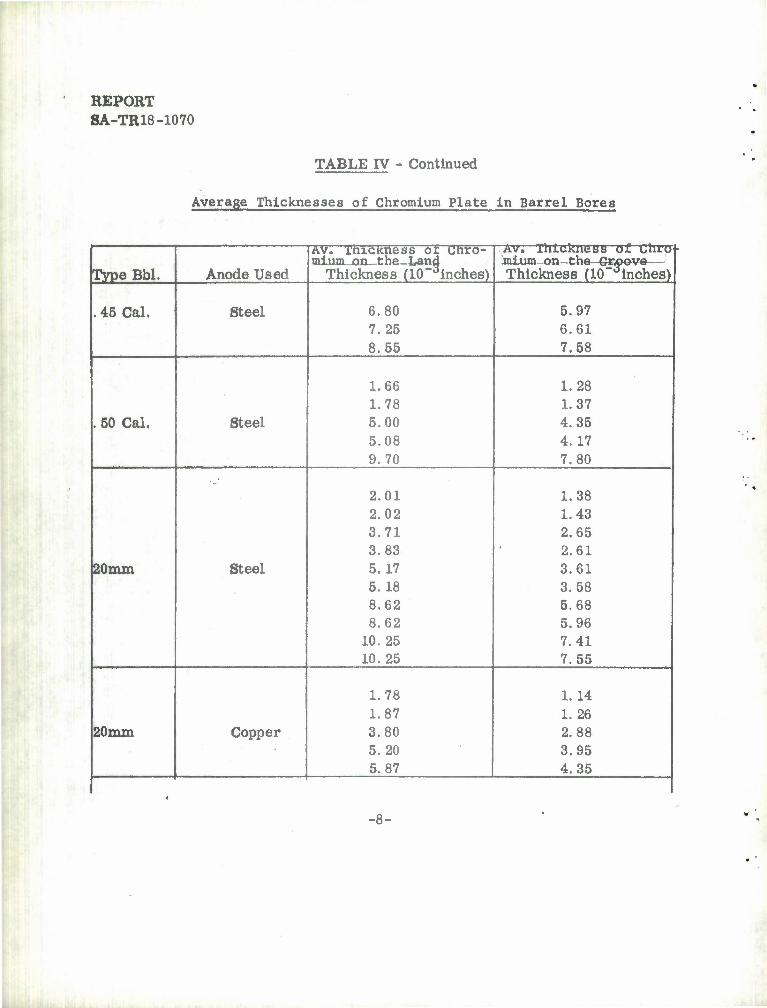
TABLE IV - Continued
Average Thicknesses of Chromium Plate In Barrel Bores
Type Bbl. Anode Used
AV. xhicKness or unro- mium on_the-Land
Thickness (10"Jinches)
Av. Thickness of uhro inium-on—t he-Groove— Thickness (10"dInches)
. 45 Cal. Steel 6.80 5.97 7.25 6.61 8.55 7.58
1.66 1.28 1.78 1.37
. 50 Cal. Steel 5.00 4.35 5.08 4.17 9.70 7.80
•-'
2.01 1.38 2.02 1.43 3.71 2.65 3.83 2.61
20mm Steel 5.17 3.61 5.18 3.58 8.62 5.68 8.62 5.96
10.25 7.41 10.25 7.55
1.78 1.14 1.87 1.26
20mm Copper 3.80 2.88 5.20 3.95 5.87 4.35
-8-
REPORT SA-TR18-1070
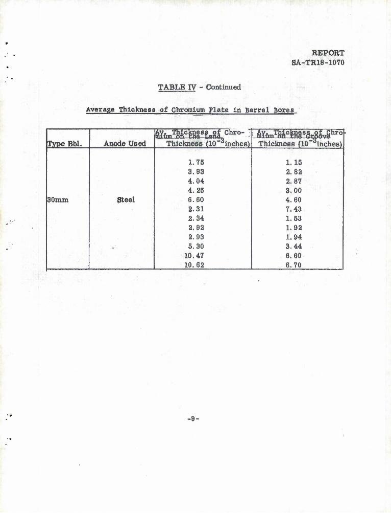
TABLE IV - Continued
Average Thickness of Chromium Plate In Barrel Bores
8Xum!o£3m*SCChro- - ^yftmT^ck^§8gt At**6
Type Bbl. Anode Used Thickness (10~dinches) Thickness (10" inches)
1.75 1.15 3.93 2.82 •
4.04 2.87 4.25 3.00
30mm Steel 6.60 2.31 2.34
4.60 7.43 1.53
•
2.92 2.93
1.92 1.94
»^' 5.30 10.47 10.62
3.44 6.60 6.70
-9-

REPORT SA-TR18-1070
9 IO II 12
Land Chromium Thickness (10 inches)
-10-
REPORT SA-TR18-1070
Land Chromium Thickness (10 inches)
-11-
REPORT SA-TR18-1070
'.
••
3 4-56789 Land Chromium Thickness (10~3inches)
IO II 12.
-12-
REPORT SA-TR18-1070
4. DISCUSSION OF RESULTS - Continued
examined) decreases as the barrel size increases. The exception to this pattern appears in the case of the . 45 caliber barrels, where the curve approximates that of the . 30 caliber barrel.
b. Anode material (copper or steel) appears to have little effect on the groove-to-land chromium thickness ratio.
5. CONCLUSIONS
The ratio of lund-to-groove chromium plating thickness has been established (See Figures 1, 2, and 3)for . 30 caliber, . 45 caliber, . 50 caliber, 20mm, and 30mm barrel bores. The ratios apply to barrel bores which have been chrom- ium plated under existing plating procedures used at the Springfield Armory.
0. RECOMMENDATIONS
A study should be made to determine the change of inside diameter of the bores (measured at the grooves) resulting from the difference of steel re- moval during electropolishing and chromium deposited during plating.
This report was edited under Contract DA-19-020-504-ORD-4800 by Associated Engineers, Inc., from technical data compiled by Springfield Armory.
-13-
DISTRIBUTION
REPORT SA-TR18-1070
Chief of Ordnance Department of the Army ,/
Copies
2
L^ Washington 25, D. C. ATTN: ORDTB
ORDER (1) (1)
Commanding General .^Ordnance Weapons Command
Rook Island, Illinois ATTN: ORDOW-FM (1)
ORDOW-TX (1) ORDOW-PEQUA (1) ORDOW-lE (1)
Commanding Officer Diamond Ordnance Fuze Laboratories
^^Washington 25, D. C. ATTN: Technical Reference Section
ORDTL 06.33
2^Armed Services Technical Information Agency Arlington Hall Station Arlington 12, Virginia
Commanding Officer [/ Detroit Arsenal
Center Line, Michigan
Commanding .Officer ly/ Frankford Arsenal
Philadelphia, Pennsylvania ATTN: Pitman-Dunn Laboratory (1)
Small Arms Division (1) (i)
10
REPORT SA-TR18-1070
DISTRIBUTION - Continued
Copies
Commanding Officer 2 t/'Picatinny Arsenal
Dover, New Jersey ATTN: ORDBB-TM2
/
Commanding General 2 U. S. Army Ordnance Arsenal Redstone Arsenal, Alabama
Commanding Officer 1 Rock Island Arsenal
/ Rock Island, Illinois ATTN: Laboratory
Commanding Officer 2 •. Watertown Arsenal
(^ Watertown, Massachusetts ATTN: Laboratory (1)
Ordnance Materials Research Office (1)
Commanding Officer 1 . Watervliet Arsenal
*^ Watervliet, New York ATTN: Laboratory
y
Commanding General Aberdeen Proving Ground Aberdeen, Maryland ATTN: ORDBG-DPD
(ii)
REPORT SA-TR18-1070
DISTRIBUTION - Continued
Commanding General L Fort Monmouth, New Jersey
ATTN: Signal Corps Engineering Laboratory Squier Signal Laboratory - Materials Section
•
Commanding General JPort Belvoir, Virginia ATTN: Research and Development Laboratories
Materials Branch
Copies
1
Commanding Officer Office of the Quartermaster General
C/^ Washington 25, D. C. ATTN: Research and Development Division
Chemicals and Plastics Branch -
Commanding Officer Office of Ordnance Research
i-^Post Office Box CM, Duke Station Durham, North Carolina
President, U. 8. Army Infantry Board {/ United States Continental Army Command
Fort Bennlng, Georgia
President, U.8. Army Armor Board I United States Continental Army Command
Fort Knox, Kentucky
X. Commanding General U. 8. Army Ordnance Special Weapons Ammunition Command Dover, New Jersey
(ill)
REPORT SA-TR18-1070
DISTRIBUTION - Continued
y Commander Air Materiel Command Engineering Division, Materials Laboratory Wright-Patterson Air Foroe Base, Ohio
/Commander Air Proving Ground Center Eglln Air Force Base, Florida ATTN: PGTRI, Teoh. Lib.
Commander Air Research and Development Command Andrews Air Force Base Washington 25, D. C. ATTN: RDT-DAG
Chairman, National Aeronautics and Space Administration Lewis Research Center 21,000 Brookpark Road Cleveland 35, Ohio
J
Director, Office of Naval Research Department of the Navy /
y Washington 25, D. C. ATTN: Code 423
Chief, Bureau of Aeronautics Department of the Navy
/ Airborne Equipment Division «• Washington 25, D. C.
ATTN: Materials Branch, Code AE-44
(iv)
^
Copies
1
DISTRIBUTION - Continued
REPORT SA-TR18-1070
Commander U.S. Naval Ordnance Laboratory
V_/ Department of the Navy 8050 Georgia Avenue / Silver Spring, Maryland ATTN: Code WC-1
Chief, Bureau of Ships /v , Department of the Navy ^-^^ Washington 25, D. C.
ATTN: Research and Development Division - Code 346 (1) Material Development Division - Code 345 (1)
Director . yU.S. Naval Research Laboratory
Washington 20, D. C. ATTN: Technical Information Officer
Copies
1
2
Chief, Bureau of Ordnance j j Department of the Navy
^ Washington 25, D. C. ATTN: Research and Development Division
Materials and Handling Branch - Code Re-1
Commander, U. S. Naval Air Experimental Station Building 600 Philadelphia 12, Pennsylvania
Superintendent w U. S. Naval Weapons Plant
Washington 25, D. C. /
(v)
*«
REPORT SA-TR18-1070
DISTRIBUTION - Continued
Copies
COPIES OF THIS UNCLASSIFIED REPORT WERE TRANSMITTED BY SPRINGFIELD ARMORY DIRECT TO THE FOLLOWING ADDRESSEES:
Director, National Bureau of Standards Department of Commerce Washington 25, D. C. ATTN: Electrodeposition Section
Division of Chemistry
Associated Engineers, Inc. / 1 Silver Street Agawam, Massachusetts ATTN: Mr. A.J. Rettie, Project Engineer
Mr. E. M. Pietras, Technical Writer
TWO COPIES OF THIS REPORT WERE TRANSMITTED BY SPRINGFIELD ARMORY TO THE FOLLOWING ADDRESSEE BY SPECIAL COVER LETTER IN ACCORDANCE WITH OCTI-200-4-57, PAR. 9a:
Office of Technical Services Department of Commerce Washington 25, D. C. ATTN: Acquisitions Sections
(vi)