julian tornow 18.01 - max planck society · julian tornow modern methodsin ... (pvd) atomar...
TRANSCRIPT

Fritz Haber Institute of the Max Planck Society
- Department of inorganic chemistry -
Chemical Vapor Deposition
18.01.2013
Julian Tornow
Modern Methods in Heterogeneous Catalysis,
FHI Berlin
18.01.2013
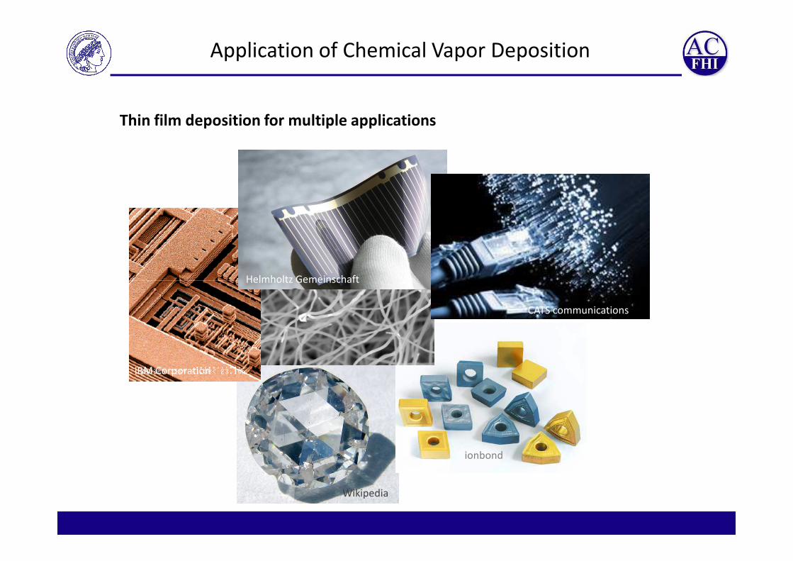
Application of Chemical Vapor Deposition
Helmholtz Gemeinschaft
Thin film deposition for multiple applications
Wikipedia
IBM Corporation
Helmholtz Gemeinschaft
CATS communications
ionbond

What is a thin solid film?
Definition by thickness: < 1µm
Definition by properties: dominanted by surface properties
Definition by deposition: molecular bottom up growth (CVD or PVD)
Thin solid silicon film on graphite
(by chemical vapor deposition)
1 µm
5 µm
Thick solid silicon/carbon film
(by tape casting)
Chemical vs. Physical Vapor Deposition
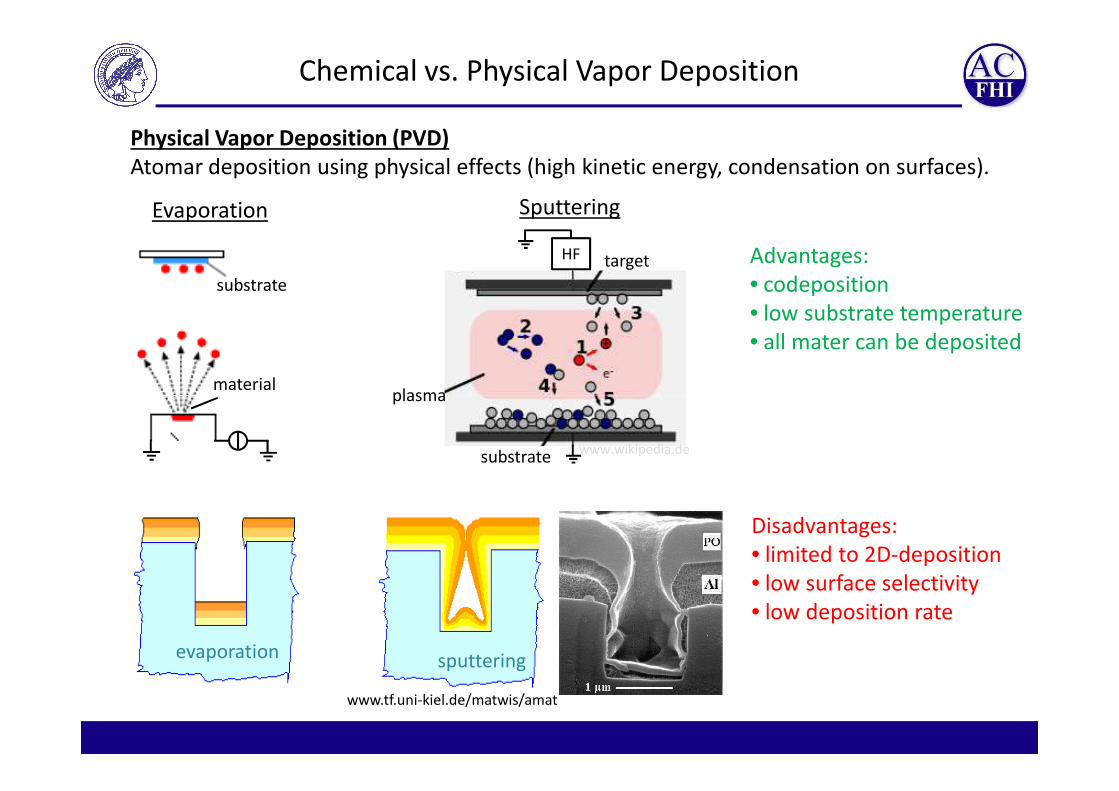
Physical Vapor Deposition (PVD)
Atomar deposition using physical effects (high kinetic energy, condensation on surfaces).
target
plasma
HF
SputteringEvaporation
substrate
material
Advantages:
• codeposition
• low substrate temperature
• all mater can be deposited
substrate
plasma
www.wikipedia.de
sputteringevaporation
www.tf.uni-kiel.de/matwis/amat
Disadvantages:
• limited to 2D-deposition
• low surface selectivity
• low deposition rate
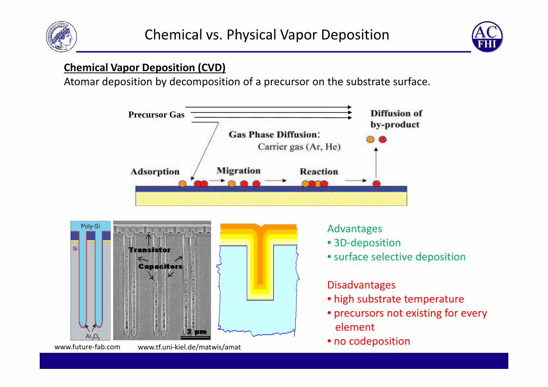
Precursor Gas
Chemical Vapor Deposition (CVD)
Atomar deposition by decomposition of a precursor on the substrate surface.
Chemical vs. Physical Vapor Deposition
www.future-fab.com www.tf.uni-kiel.de/matwis/amat
Advantages
• 3D-deposition
• surface selective deposition
Disadvantages
• high substrate temperature
• precursors not existing for every
element
• no codeposition

Typical CVD reactions
Pyrolysis (thermally activated decomposition)
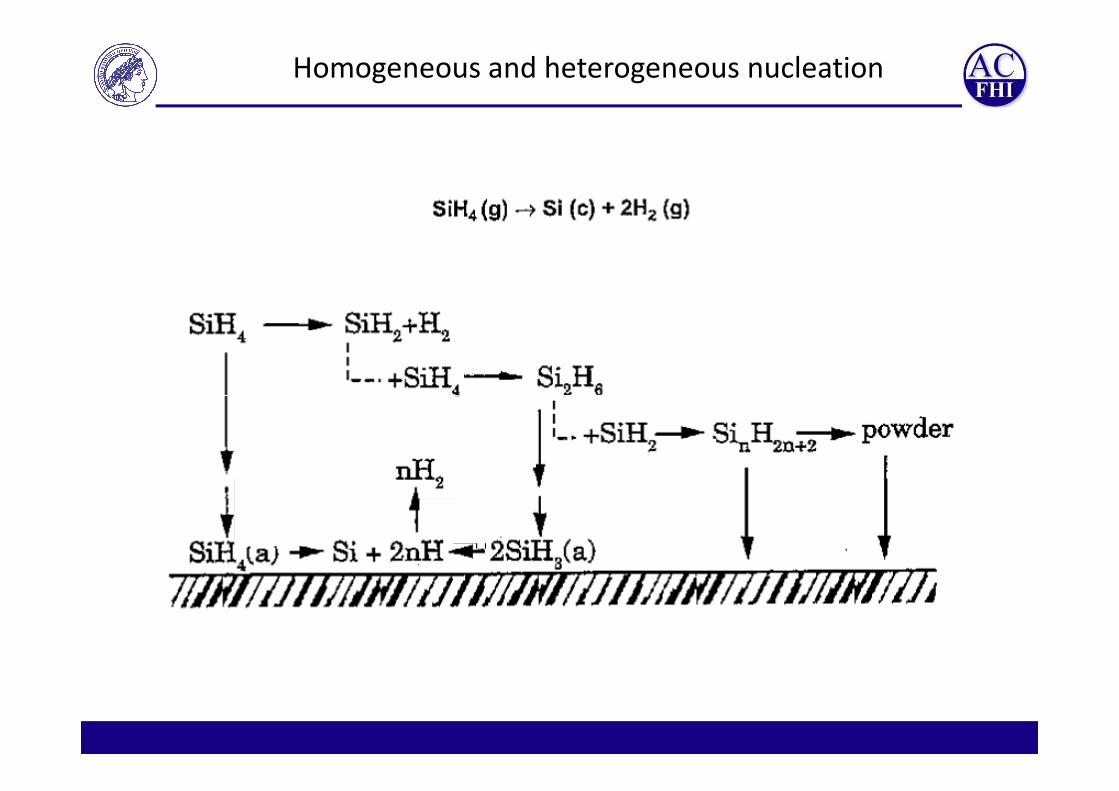
SiH4 (g)→ Si (c) + 2H2 (g)
SiH2Cl2 (g) → Si (c) + 2HCl (g)
CH4 (g)→ C (graphite, diamond) + 2H2 (g)
Ni(CO)4 (g) → Ni (c) + 4CO (g)
Oxidation
SiH4 (g) + 2O2 (g) → SiO2 (c) + 2H2O (g)
3SiH (g) + 4NH (g) → Si N (c) + 12H (g)3SiH4 (g) + 4NH3 (g) → Si3N4 (c) + 12H2 (g)
Reduction
WF6 (g) + 3H2 (g) → W (c) +6HF (g)
SiHCl3 (g) + H2 (g) → Si (c) + 3HCl (g)
Hydrolysis
2AlCl3 (g) + 3H2O (g) → Al2O3 (c) + 6HCl (g)
Exchange
Ga(CH3)3 (g) + AsH3 (g) → GaAs (c) + 3CH4 (g)

Nucleation
Total interface energy
rArArAG γγγ 222 −+∝∆
SiH4 (g)→ SiH4 (p) → Si (c) + 2H2 (g)
Difficult nucleation if precursor-precursor bonding is stronger than
precursor-substrate-bonding → island growth, inhomogeneous coverage
siiikkI rArArAG γγγ 222 −+∝∆
Volume energy
molsatV V
rk
p
pRTG
3
ln⋅
−=∆
Stable nucleus if IV GG ∆>∆
M. Ohring; Academic Press 1992
Homogeneous and heterogeneous nucleation
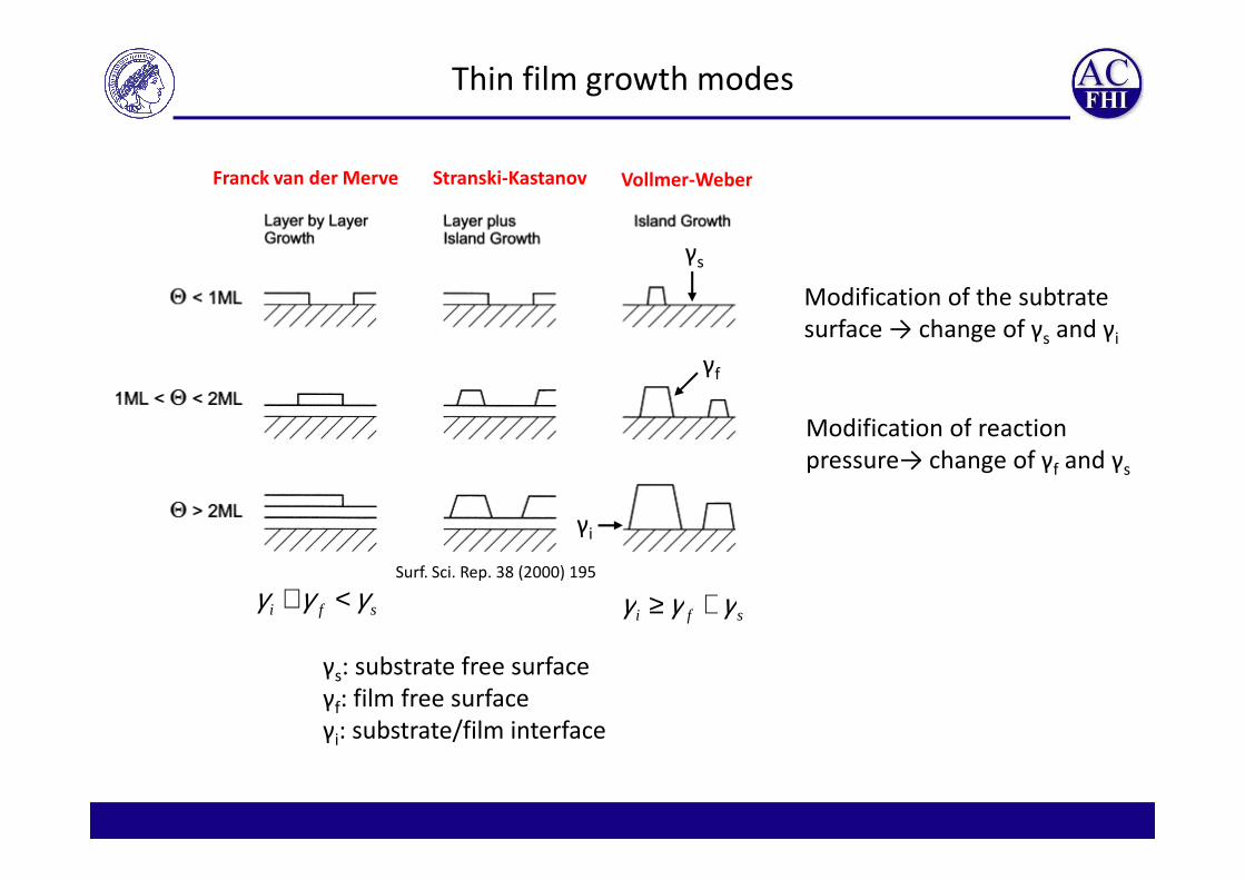
Thin film growth modes
Franck van der Merve Stranski-Kastanov Vollmer-Weber
γs
γf
Modification of the subtrate
surface → change of γs and γi
Modification of reaction
Surf. Sci. Rep. 38 (2000) 195
sfi γγγ <+sfi γγγ +≥
γi
γs: substrate free surface
γf: film free surface
γi: substrate/film interface
Modification of reaction
pressure→ change of γf and γs

Temperature dependency of growth rate
Reaction limited regime
Typically Arrhenius behavior
=RT
EAR Aexp
Mass transport limited regime
Diffusion limited transport of
precursor to the reactive surface
Desorption regime
Desorption of deposited material or
alternative reaction pathwaysHitchman, M. et al; London academic press 1993

Constructing a CVD-reactor

Membrane
valves Filter 2
µm
Reaction gas premixing
Quarztube
Check valvesMass Flow
Controller
Graphitrohr
Coil
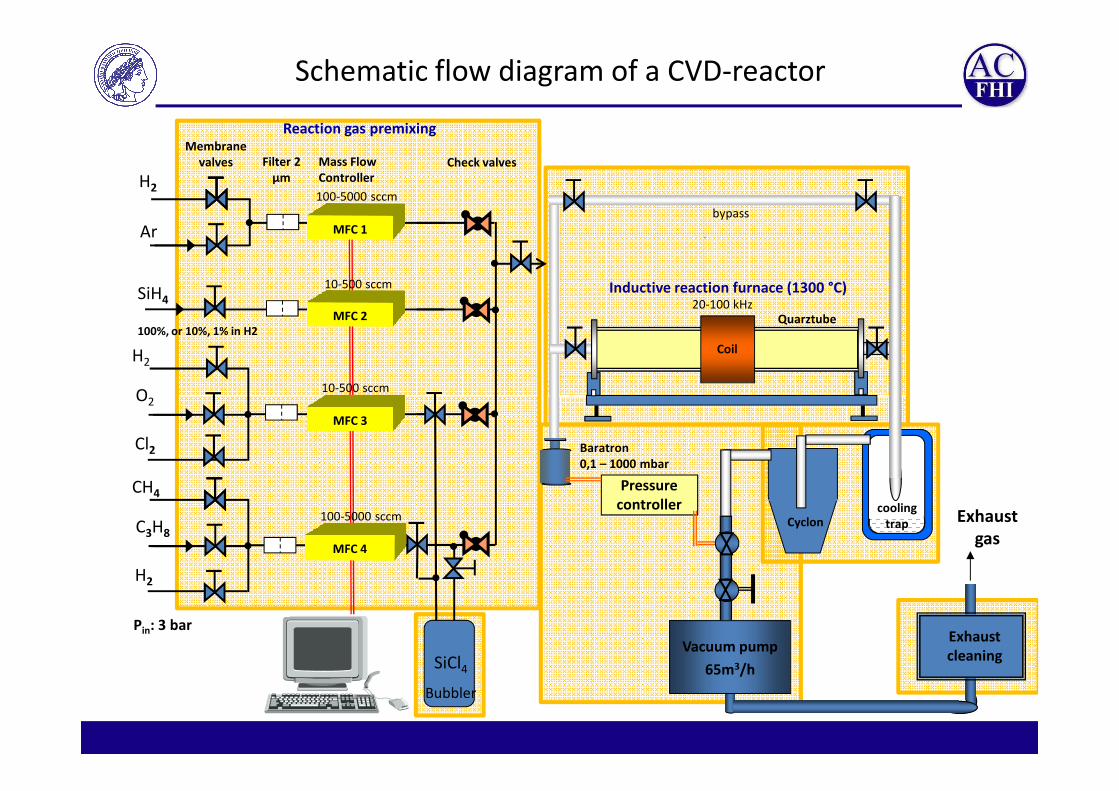
Inductive reaction furnace (1300 °C)SiH4
100%, or 10%, 1% in H2
Ar
H2
20-100 kHz
10-500 sccm
10-500 sccm
100-5000 sccm
O2
H2
bypass
Schematic flow diagram of a CVD-reactor
Pin: 3 bar
Pirani
0,1 – 1000 mbar
Pressure
controllerExhaust
gas
Exhaust
cleaningVacuum pump
65m3/h
cooling
trapCyclonC3H8
CH4
H2
100-5000 sccm
O2
Cl2
SiCl4
Bubbler

Reaction gas premixing

Mass flow controller (MFC)
Electronic
controller
MFM
Control valve
Gaswww.bronkhorst.de
www.bronkhorst.de

Membrane
valves Filter 2
µm
Reaction gas premixing
Quarztube
Check valvesMass Flow
Controller
Graphitrohr
Coil
Inductive reaction furnace (1300 °C)SiH4
100%, or 10%, 1% in H2
Ar
H2
20-100 kHz
10-500 sccm
10-500 sccm
100-5000 sccm
O2
H2
bypass
Schematic flow diagram of a CVD-reactor
Pin: 3 bar
Pirani
0,1 – 1000 mbar
Pressure
controllerExhaust
gas
Exhaust
cleaningVacuum pump
65m3/h
cooling
trapCyclonC3H8
CH4
H2
100-5000 sccm
O2
Cl2
SiCl4
Bubbler

Liquid precursor transport via bubbler
www.fluidat.com
satbub
satN
N
satNV pp
pQ
p
pQQ
−==
2
2
2
• saturation of carrier gas bubbles with precursor
• saturation within a few mm bubble distance
Mass flow of precursor QV:
→ AlternaGve to bubbler: Evaporator
(heating of tubes might be necessary)
STREM Chemicals
Bronkhorst
J. Vac. Sci. Technol: 19 (2001)329

Membrane
valves Filter 2
µm
Reaction gas premixing
Quarztube
Check valvesMass Flow
Controller
Coil
Inductive reaction furnace (1300 °C)SiH4
100%, or 10%, 1% in H2
Ar
H2
20-100 kHz
10-500 sccm
10-500 sccm
100-5000 sccm
O2
H2
bypass
Schematic flow diagram of a CVD-reactor
Pin: 3 bar
Pirani
0,1 – 1000 mbar
Pressure
controllerExhaust
gas
Exhaust
cleaningVacuum pump
65m3/h
cooling
trapCyclonC3H8
CH4
H2
100-5000 sccm
O2
Cl2
SiCl4
Bubbler

Reactor geometries
And several others…
Hitchman, M. et al; London academic press 1993

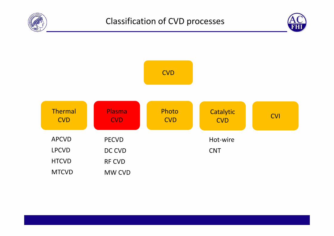
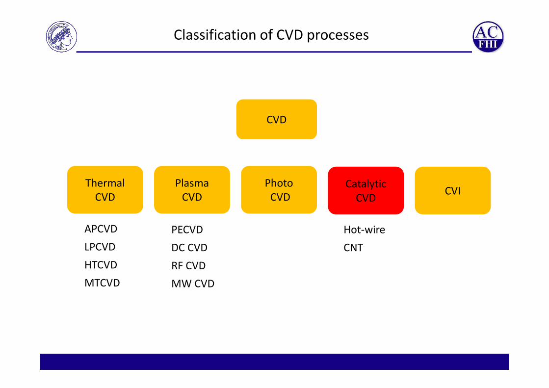
Classification of CVD processes
CVD
Thermal
CVD
Plasma
CVD
Photo
CVDCVI
Catalytic
CVDCVD CVD CVDCVI
CVD
APCVD
LPCVD
HTCVD
MTCVD
PECVD
DC CVD
RF CVD
MW CVD
Hot-wire
CNT

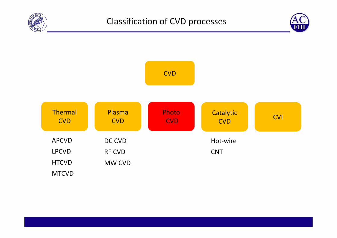
Classification of CVD processes
CVD
Thermal
CVD
Plasma
CVD
Photo
CVDCVI
Catalytic
CVDCVD CVD CVDCVI
CVD
APCVD
LPCVD
HTCVD
MTCVD
PECVD
DC CVD
RF CVD
MW CVD
Hot-wire
CNT
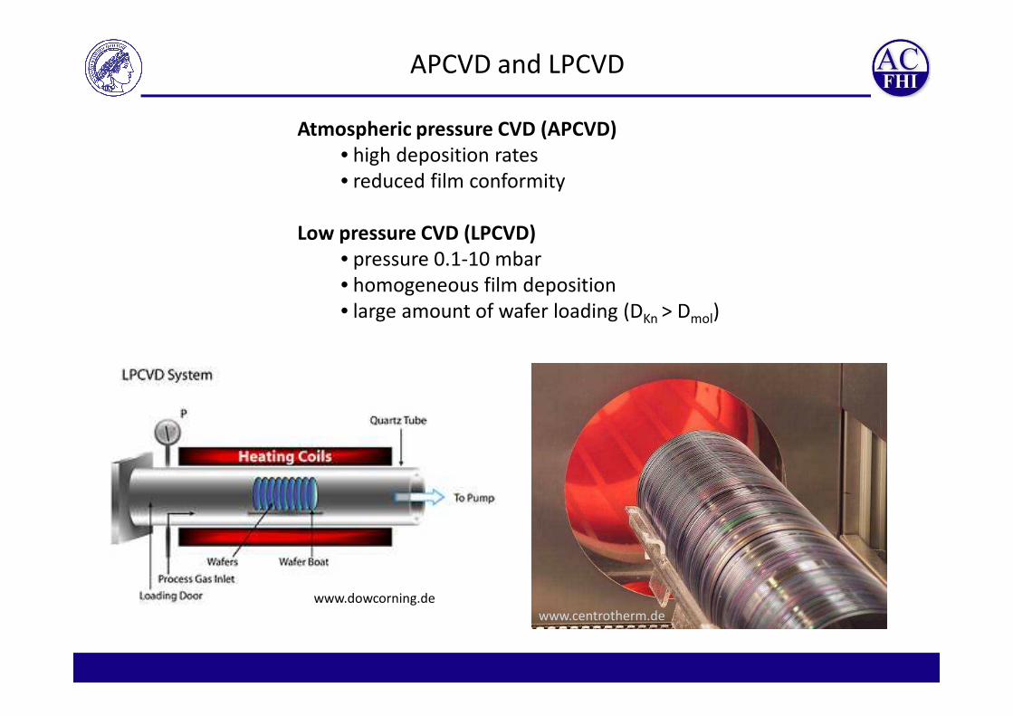
APCVD and LPCVD
Atmospheric pressure CVD (APCVD)
• high deposition rates
• reduced film conformity
Low pressure CVD (LPCVD)
• pressure 0.1-10 mbar
• homogeneous film deposition
• large amount of wafer loading (DKn > Dmol)
www.dowcorning.de
www.centrotherm.de

Hot wall vs. cold wall reactor
Hot wall reactor Cold wall reactor
• heating of the whole reactor tube
• good temperature control
• deposition on the tube wall
(esp. for endothermic reactions)
• Method: resistive
• heating only the sample or a susceptor
inside the reactor tube
• inhomogeneous temperature profile
• reaction only at sample (especially for
endothermic reactions)
• Methods: inductive, capacitive, IR,
Microwave
Classification of CVD processes
CVD
Thermal
CVD
Plasma
CVD
Photo
CVDCVI
Catalytic
CVDCVD CVD CVDCVI
CVD
APCVD
LPCVD
HTCVD
MTCVD
PECVD
DC CVD
RF CVD
MW CVD
Hot-wire
CNT

Plasma enhanced CVD
www.spiegel.de
Mixture of molecules, ions, radicals and electrons
www.spiegel.de
• activation of precursor by plasma
• lowering of the substrate temperature
• possible substrate damage
• plasma ignition:
• DC
• RF
• MW
www.wikipedia.de

Plasma enhanced CVD
Classification of CVD processes
CVD
Thermal
CVD
Plasma
CVD
Photo
CVDCVI
Catalytic
CVDCVD CVD CVDCVI
CVD
APCVD
LPCVD
HTCVD
MTCVD
DC CVD
RF CVD
MW CVD
Hot-wire
CNT
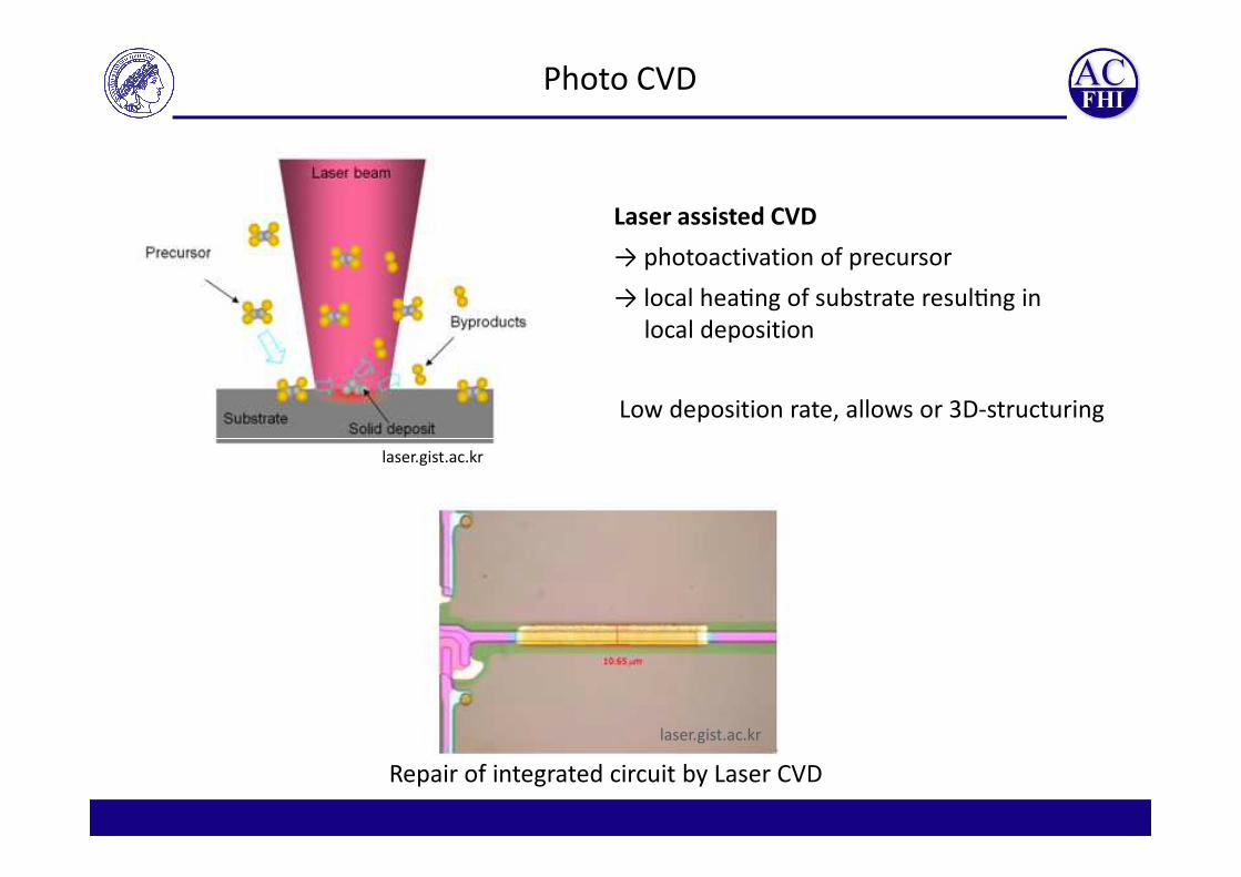
Photo CVD
Laser assisted CVD
→ photoactivation of precursor
→ local heaGng of substrate resulGng in
local deposition
Low deposition rate, allows or 3D-structuring
laser.gist.ac.kr
laser.gist.ac.kr
Repair of integrated circuit by Laser CVD
Classification of CVD processes
CVD
Thermal
CVD
Plasma
CVD
Photo
CVDCVI
Catalytic
CVDCVD CVD CVDCVI
CVD
APCVD
LPCVD
HTCVD
MTCVD
PECVD
DC CVD
RF CVD
MW CVD
Hot-wire
CNT

Cracking precursor bonds on hot catalyst.
Thin film deposition
(decrease substarte temperature)Growing Carbon nanotubes
Catalytic CVD
J. Nanosci. Nanotechnol. 10 (2010)3739

Classification of CVD processes
CVD
Thermal
CVD
Plasma
CVD
Photo
CVDCVI
Catalytic
CVDCVD CVD CVDCVI
CVD
APCVD
LPCVD
HTCVD
MTCVD
PECVD
DC CVD
RF CVD
MW CVD
Hot-wire
CNT

Chemical Vapor Infiltration
Deposition on porous substrates
Problem: closing of the pores
Solution I: optimized reaction rate – e.g. the rate of SiCl4 depostion can be
adjusted by the Cl/H-ratio.
Solution II: Intermittent growth by ALD or TPCVD
Problem: Inhomogeneities by temperature- or concentration gradients
Solution: Use of mass transport limited regime (→hohe T),
! Conflit with pore closing!
J. Mater. Chem. 3 (1993) 1307 J. Crystal Growth 31 (1975) 299
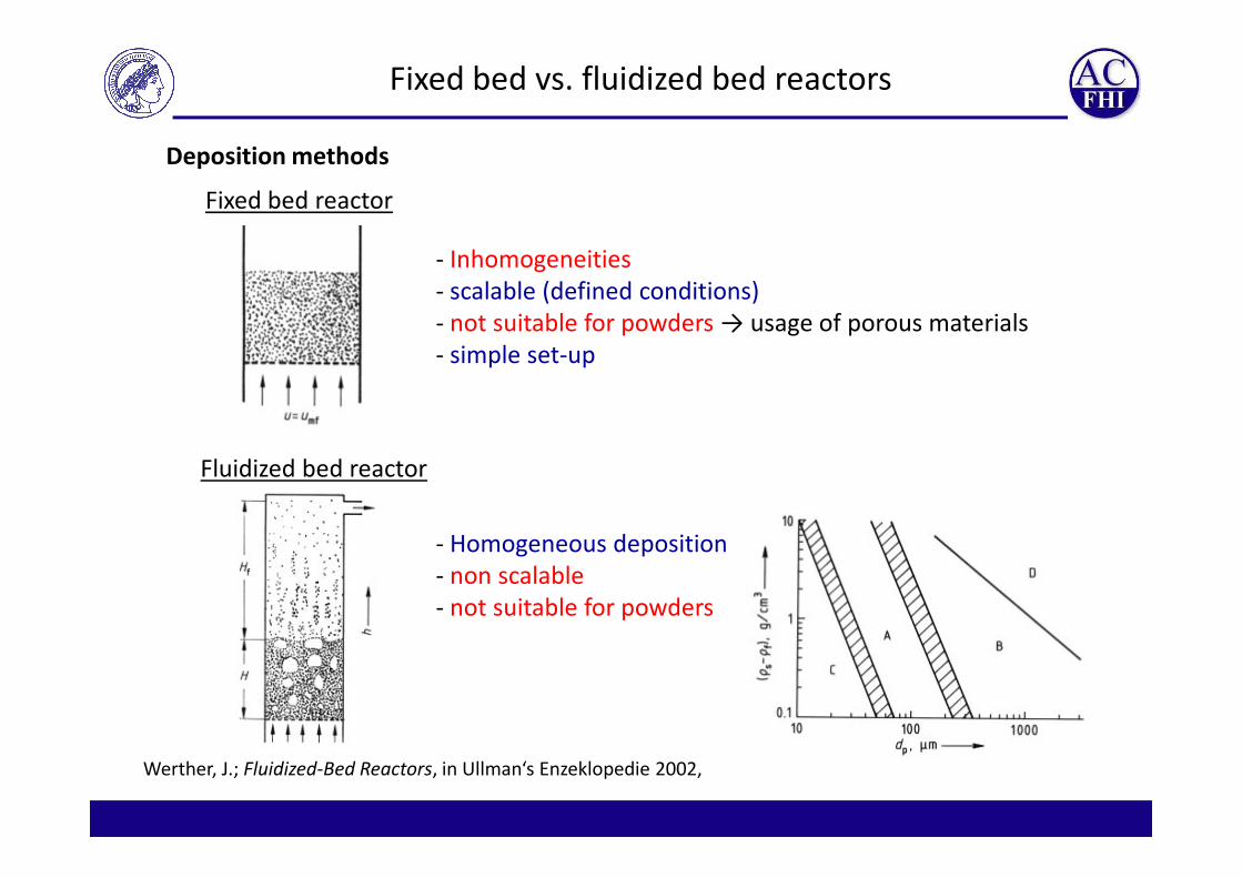
Deposition methods
Fixed bed reactor
- Inhomogeneities
- scalable (defined conditions)
- not suitable for powders → usage of porous materials
- simple set-up
Fixed bed vs. fluidized bed reactors
Fluidized bed reactor
- Homogeneous deposition
- non scalable
- not suitable for powders
Werther, J.; Fluidized-Bed Reactors, in Ullman‘s Enzeklopedie 2002,

Membrane
valves Filter 2
µm
Reaction gas premixing
Quarztube
Check valvesMass Flow
Controller
Coil
Inductive reaction furnace (1300 °C)SiH4
100%, or 10%, 1% in H2
Ar
H2
20-100 kHz
10-500 sccm
10-500 sccm
100-5000 sccm
O2
H2
bypass
Schematic flow diagram of a CVD-reactor
Pin: 3 bar
Pirani
0,1 – 1000 mbar
Pressure
controllerExhaust
gas
Exhaust
cleaningVacuum pump
65m3/h
cooling
trapCyclonC3H8
CH4
H2
100-5000 sccm
O2
Cl2
SiCl4
Bubbler

Traps for particles and chemicals
Particle traps
• Filters
• Dust-Trap
• Cyclones
Filtering particles and corrosive chemicals to protect the pump.
Chemical traps
• Absorption solids (e.g. zeolites)
• cooling traps (temperature controled)
Cooling trap for temperatures from 77-273K

Membrane
valves Filter 2
µm
Reaction gas premixing
Quarztube
Check valvesMass Flow
Controller
Coil
Inductive reaction furnace (1300 °C)SiH4
100%, or 10%, 1% in H2
Ar
H2
20-100 kHz
10-500 sccm
10-500 sccm
100-5000 sccm
O2
H2
bypass
Schematic flow diagram of a CVD-reactor
Pin: 3 bar
Baratron
0,1 – 1000 mbar
Pressure
controllerExhaust
gas
Exhaust
cleaningVacuum pump
65m3/h
cooling
trapCyclonC3H8
CH4
H2
100-5000 sccm
O2
Cl2
SiCl4
Bubbler
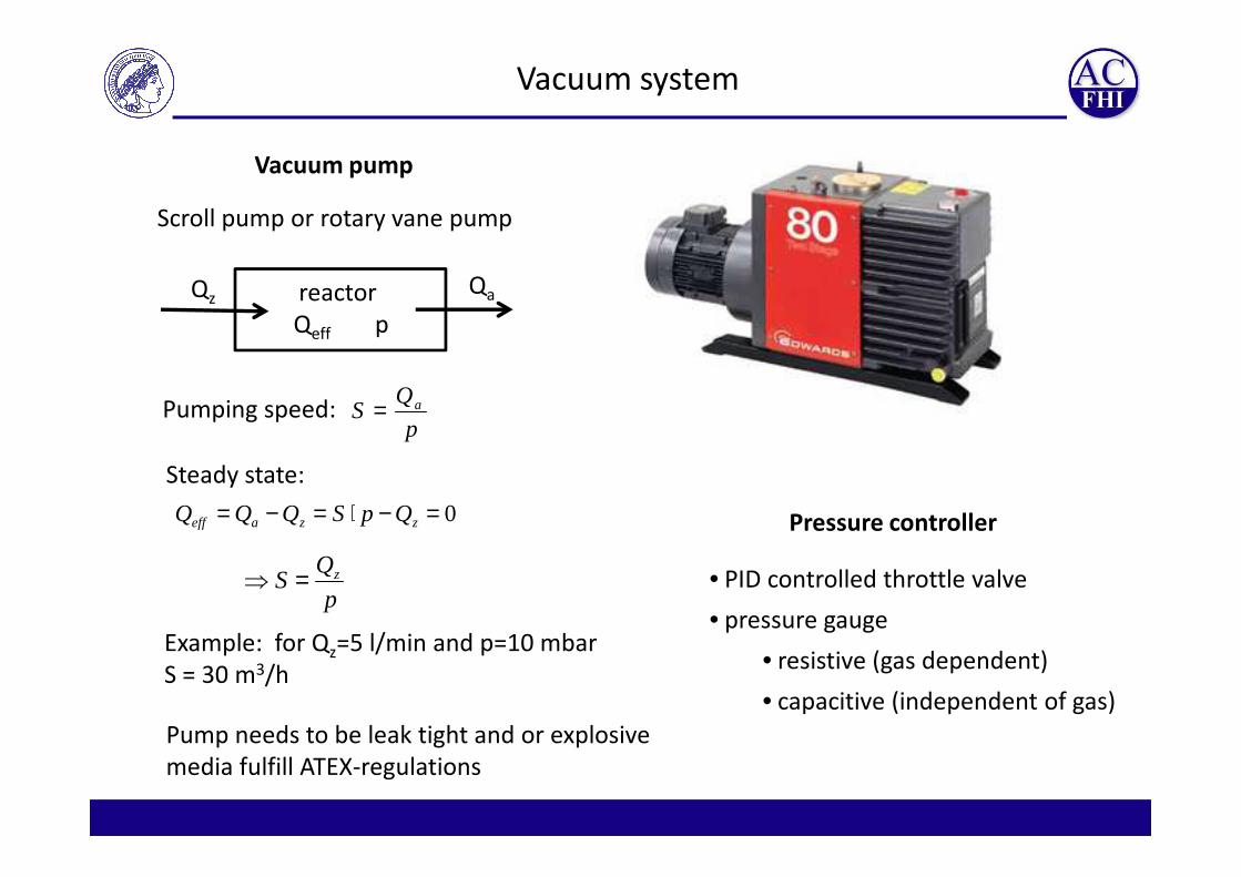
Vacuum system
Vacuum pump
Scroll pump or rotary vane pump
reactor QaQz
Qeff p
p
QS a=Pumping speed:
p
Steady state:
0=−⋅=−= zzaeff QpSQQQ
p
QS z=⇒
Example: for Qz=5 l/min and p=10 mbar
S = 30 m3/h
Pump needs to be leak tight and or explosive
media fulfill ATEX-regulations
Pressure controller
• PID controlled throttle valve
• pressure gauge
• resistive (gas dependent)
• capacitive (independent of gas)
Membrane
valves Filter 2
µm
Reaction gas premixing
Quarztube
Check valvesMass Flow
Controller
Coil
Inductive reaction furnace (1300 °C)SiH4
100%, or 10%, 1% in H2
Ar
H2
20-100 kHz
10-500 sccm
10-500 sccm
100-5000 sccm
O2
H2
bypass
Schematic flow diagram of a CVD-reactor
Pin: 3 bar
Baratron
0,1 – 1000 mbar
Pressure
controllerExhaust
gas
Exhaust
cleaningVacuum pump
65m3/h
cooling
trapCyclonC3H8
CH4
H2
100-5000 sccm
O2
Cl2
SiCl4
Bubbler
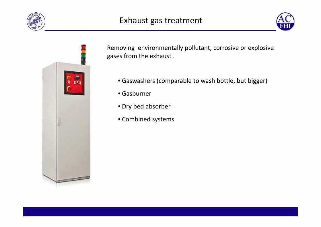
Removing environmentally pollutant, corrosive or explosive
gases from the exhaust .
• Gaswashers (comparable to wash bottle, but bigger)
• Gasburner
• Dry bed absorber
Exhaust gas treatment
• Combined systems

Construction plan of reactor (CAD)

Scrubber
Electronics & induction generator Safety gas monitoring
CVD-Reactor
Inductively
heated cold wall
reactor
Gas mixing chamber Reaction chamberVacuum pump
Computer
reactor
Precursors:
SiH4, SiHCl3, SiCl4,
CH4
Temperature:
350-1500 °C
Pressure:
5-1000 mbar
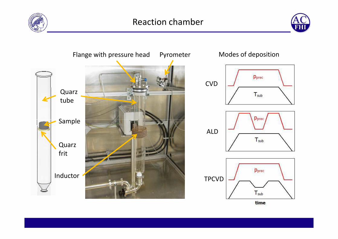
Flange with pressure head Pyrometer
Quarz
tube
Sample
Reaction chamber
Modes of deposition
CVD
Sample
Quarz
frit
Inductor
ALD
TPCVD
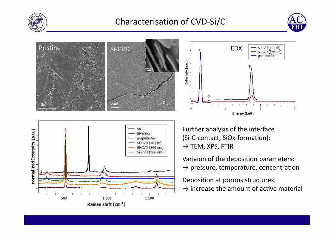
2µm2µm
500 nm
Pristine Si-CVD
Characterisation of CVD-Si/C
EDX
Further analysis of the interface
(Si-C-contact, SiOx-formation):
→ TEM, XPS, FTIR
Variaion of the deposition parameters:
→ pressure, temperature, concentraGon
Deposition at porous structures:
→ increase the amount of acGve material

Pressure variation in Si-CVD process
70 mbar 50 mbar
30 mbar 10 mbar

900 °C 1100 °C1000 °C
Temperature variation in Si-CVD process
1200 °C
EDX FTIR

Stuctural analysis of deposited films
O EFTEM Si EFTEM
TEM (Si@1100°C A)ATR-FTIR
XPS
Si@1100°C A Si@1100°C B Si@1100°C C
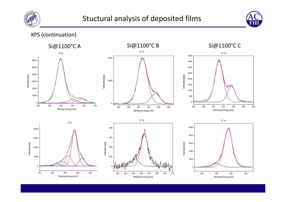
Stuctural analysis of deposited films
Si@1100°C A Si@1100°C B Si@1100°C C
XPS (continuation)

Si-CVD on titanium foil
TiCl3
• Deposition of Si at around 1020°C
• Formation of solid solution from
β-Ti and Ti3Si at hot zone?
• Etching of Ti foil by
HCl forming TiCl31144°C→1000°C
Si?
β -Ti
Foil thickness: 0.5 mm
R. J. Nemanich et al., Reactions of thin film titanium on silicon studied by Raman spectroscopy, Appl. Phys. Lett. 46, 670 (1985)
D.P. Riley, Synthesis and characterization of SHS bonded Ti5Si3 on Ti substrates, Intermetallics, 14, 770–775, 2006
β-Ti

Pristine coal
Gas C 94,00Si 2,92Fe 1,45
C 94,3Al 1,81Si 1,51Fe 1,26Ca 0,40Mg 0,27S 0,26Ti 0,14
Si-CVD on activated carbon (Epibon)
C 93,20Si 3,72Fe 1,19Al 1,08Cl 0,31Ca 0,18Ti 0,11S 0,08
Fe 1,45Al 1,20Ti 0,16Cl 0,12Ca 0,09P 0,04S 0,03
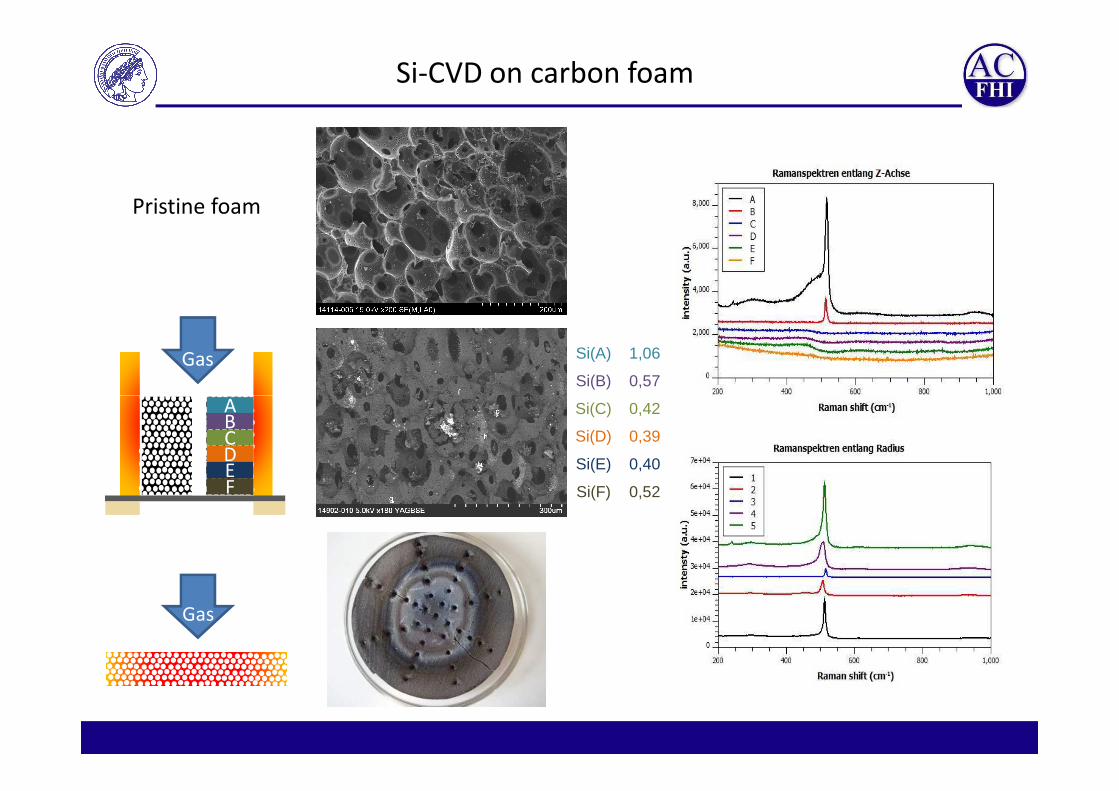
Si-CVD on carbon foam
Gas
Pristine foam
Si(A) 1,06
Si(B) 0,57
A
Gas
Si(C) 0,42
Si(D) 0,39
Si(E) 0,40
Si(F) 0,52
ABCDEF