july 12, 2003 page 2 - the cool colors project
TRANSCRIPT

Stephen Wiel, Head MS 90R4000 Tel. 510-486-5396 Energy Analysis Department 1 Cyclotron Road Fax: 510-486-6996 Environmental Energy Technologies Division Berkeley, CA 94720-8136 e-mail: [email protected]
Hashem Akbari: Phone: (1) 510 486 4287 · Fax: (1) 510 486 4673· e-mail: [email protected]
July 12, 2003 To: Chris Scruton (CEC) From: Steve Wiel Subject: Cool Roof Colored Materials: Monthly Progress Report for June 2003 CC: Hashem Akbari, Paul Berdahl, Andre Desjarlais, Bill Miller, Ronnen Levinson
A summary of the status of Tasks and Deliverables as of June 30, 2003 is presented in Attachment 1.
HIGHLIGHTS
• A report summarizing our activities and analysis for Task 2.5.1 “Review of Roofing Materials Manufacturing Methods” is completed (see Attachments).
• Wiel visited Mike Evans of Evans Construction and toured Cavalli Hills, a new subdivision being built in Sacramento. These homes will be used to demonstrate cool colored roofing materials.
• FERRO, Hanson Tile, Shepherd, Monier Life Tile, and the Roof Tile Institute are cooperating to produce cool-colored concrete samples for the field exposure test sites.
Tasks 1.1 Attend Kick-Off Meeting This Task is completed.
1.2 Describe Synergistic Projects This Task is completed. 2.1 Establish the Project Advisory Committee (PAC)
This Task is completed. 2.2 Software Standardization (No activity.) 2.3 PAC Meetings Planning for September 11, 2003 PAC meeting is started. 2.4 Development of Cool Colored Coatings 2.4.1 Identify and Characterize Pigments with High Solar Reflectance

July 12, 2003 Page 2
Our June activities followed five tracks: (1) refining our theory, and working to complete our journal paper on the subject; (2) computing pigment volume concentrations; (3) preparing and characterizing additional paints; (4) preparing and characterizing paint tints (mixtures of colors with white); and (5) resolving several optical measurement phenomena that appeared to yield unphysical results. (1) Theory refinement. A major challenge in the calculation of Kubelka-Munk scattering and absorption coefficients is to correctly compute and correct for reflectances that occur at the interface of two media with different refractive indices (e.g., air and paint). This is particularly important when diffuse light passes from a paint film into the air, because the theoretical value of the interface reflectance is quite high (about 0.6), and actual values vary widely (measurements have yielded values of 0.2 to 0.7). Prior versions of our model have estimated this interface reflectance by varying its value to minimize the difference between a computed and measured value of the reflectance of a film over a black background. This technique has been reasonably successful, but the value of the interface reflectance so computed can be physically inconsistent with calculated values of the scattering and absorption coefficients. Hence, we have developed a new model that relates the interface reflectance to the scattering and absorption coefficients, and appears to provide much better agreement between measured and computed values of film reflectances over various backgrounds. (2) Computing pigment volume concentrations. The physical nature of a paint film is typically described by specifying its pigment, vehicle (binder), thickness, and pigment volume concentration (PVC). The latter is the fraction of the paint film's volume occupied by pigment particles, and is a parameter by which paints are designed. We developed two techniques for calculating PVC. The first method estimates PVC from wet paint density, dry pigment density, binder density, and the extent of solvent loss when a paint film dries. It can be applied to any paint, but may be inaccurate when the density of the pigment density is close to that of the binder. The second method couples the above information with manufacturer reports of pigment loading in the wet paint (pigment mass/wet paint mass). The latter, more accurate method is preferable when pigment loading data are available. We have used these methods to calculate PVCs for about the 60 or so mono-pigment paints characterized to date. (3) Preparing and characterizing additional paints. The Ferro Corporation has provided us with 11 cool Ferro pigments in the form of pre-dispersed concentrates ("dispersions"). These concentrates can be let down (mixed with) a binder to produce paint, which is simpler than making paint by milling pigments into a binder. We have prepared and measured films drawn from paints made from these dispersions. The Shepherd Company has also arranged to provide us with dispersions of its cool color pigments, which we expect to receive and process next month. (4) Preparing and characterizing paint tints. To prepare for the next stage of our project (using our model to predict the optical properties of paint mixtures), we have created and measured films made from mixtures of mono-pigments paints with white paint, or tints. We have created and measured 1:4 and 1:9 (volume color : volume white) tints of about half of the mono-pigment artist color paints, and will tint the remaining mono-pigment paints next month. (5) Resolving optical measurement phenomena. We have observed several puzzling phenomena when measuring the optical properties of paint films. The first occurs when the reflectance of an opaquely thick diffusing paint film (e.g., 2 mm of white paint) on a
July 12, 2003 Page 3
clear glass substrate is measured with a spectrometer equipped with an integrating sphere. We found that the reflectance measured with the film below the glass (solar reflectance=0.8) was significantly lower than that observed with the film above the glass (solar reflectance=0.9). This should not happen, because the glass and film have the same reflective index. We investigated this behavior by illuminating the film/glass system with a red laser beam, which demonstrated that when the film is behind the glass, some light travels laterally through the glass and does not enter the integrating sphere. This observation suggests that is may be necessary to take care of this phenomenon when measuring the reflectance of a paint film covered with a thick clear coat, since a thick clear coat may behave much like glass. A thin clear coat does not appear to cause difficulty. The second puzzling phenomenon is that sometimes the spectrometer-measured reflectance and transmittance of a film sample sum to a value greater than one. This appears to be due to a minor design flaw common to integrating spheres related to the presence of two separate light detectors (one for UV and visible light, and another for near-infrared light). We will discuss this issue and its resolution in greater detail next month.
2.4.2 Develop a Computer Program for Optimal Design of Cool Coatings See Task 2.4.1. No major activity in June.
2.4.3 Develop a Database of Cool-Colored Pigments (No activity.) 2.5 Development of Prototype Cool-Colored Roofing Materials 2.5.1 Review of Roofing Materials Manufacturing Methods
We have prepared a draft report summarizing our activities and analysis for Task 2.5.1. The report focuses on manufacturing methods for colored roofing granules, shingles, metal roofing, and clay rooftiles. Our industrial partners who participated in the Task have reviewed and provided comments. The revised report is attached; we will shortly post the report on the web. Publication of this report will mark the completion of the task.
2.5.2 Design Innovative Methods for Application of Cool Coatings to Roofing Materials (No activity.)
2.5.3 Accelerated Weathering Testing (No activity.) 2.6 Field-Testing and Product Useful Life Testing
FERRO and Shepherd are both sending representatives this July (2003) to support the Roof Tile Institute with the manufacture of concrete tiles with cool colored materials. FERRO is working with Hanson to produce cool colored tile for the demonstration homes, and Shepherd is working with Monier Life Tile to develop the concrete samples for the field exposure test sites. Both FERRO and Shepherd successfully matched the manufacturer’s standard and cool colors. Steve Wiel visited Mike Evans of Evans construction. Steve reports: “Mike has permits for all 12 lots and is nearing completion of the common infrastructure as you can see in the attached photos. He expects to start laying foundations for a few lots in two or three weeks. He hasn't yet decided how many to build now and how fast to finish out the project.

July 12, 2003 Page 4
Mike is very pleased to be part of our project. I explained all about our CEC project, the project partners, the CEC, urban heat islands, and passive residential space conditioning (my past life as a solar home designer came in handy). I left him with tons of info (the project 2-and 6-pagers, our list of project stakeholders, a briefing on urban heat islands, LBNL propaganda -- see note below). He seemed pleased to learn that the only demo houses we're doing are with him. The following photos show the subdivision from standing near the entrance to the one-block cul-de-sac and Mike and two of his workers. It's almost time to invite Chris Scruton and colleagues to visit. Mike is expecting that.”
2.6.1 Building Energy-Use Measurements at California Demonstration Sites
Ken Loyle of FERRO has arranged to work with John Quigley of Hanson Roof Tile to make the concrete tiles for the demonstration houses being built in Sacramento. Ken will spend about a week at the Rialto, CA plant to support manufacturer of the concrete tiles with cool colored pigments. John Quigley of Hanson agreed to forward samples of both low profile and S-Mission tile to Evan Construction for Mike Evans approval of the proposed roof materials. The calibrations of the heat flux transducers embedded in oriented strand board sandwich panels were completed this period. The panels are being equipped with additional thermometry for measuring surface, air gap, deck and the underside deck temperatures in the demonstration homes. Data acquisition equipment is being programmed by Campbell Scientific with delivery of DAS equipment scheduled July 31, 2003. Wim Boss of the Sacramento Municipal Utility District (SMUD) forwarded two power meters to Campbell Scientific for setup of the data collection programming. SMUD is working with LBNL and ORNL on DAS setup and is providing power instruments and setup support for the total and HVAC power metering of the demonstration homes. SMUD also will provide independent phone lines for each DAS to weekly download the field data.
2.6.2 Materials Testing at Weathering Farms in California Shepherd Color Company shipped several packages of color pigments to Monier Life Tile for making the concrete tile samples with cool colored pigments. The samples will be placed in the seven CA field sites. Shepherd is also sending a technician, John Schubert, to help expedite manufacture of the samples at Monier’s Rialto, CA plant. John will catalog the reflectance measurements of the samples using Shepherd’s Device & Services reflectometer. After the samples are ready, ORNL personnel may visit the Rialto

July 12, 2003 Page 5
site and make emittance measurements to help quicken setup of the exposure rack systems with all test roof materials. Emittance measures of the MCA clay tile samples showed little variation in measurement. MCA supplied their adobe gray, white buff, weathered green, natural red, regency blue, apricot buff, and ironwood clay tile colors, and the standard deviation in emittance measures for all the clay tile samples was only ± 0.03 (Figure 1).
0.0
0.1
0.2
0.3
0.4
0.5
0.6
0.7
0.8
0.9
1.0
AdobeGray
White Buff WeatheredGreen
NaturalRed
RegencyBlue
ApricotBuff
Ironwood
Emitt
ance
( ε)
Series 800 Clay tile
Series 900 Clay tileStandard Deviation of all Clay Tiles
ε = ± 0.03
Accurate measurement using the Device & Services emissometer requires that the test sample remain at the same temperature as the calibration standards. However, the thermal mass of the clay samples and the low thermal conductivity of the clay caused a gradual heating of the samples irradiated by the detector. We therefore used a transient technique to extrapolate the emittance back to the start of the measurement process where the surface would be close to its original temperature and that of the standard. The results of the technique are shown in Figure 2 for the adobe gray clay tile. Emittance measures were recorded every 30 sec over a 4-min interval for clay tile samples covered with a tape of known emittance and also for the bare sample. The ratio of the two values of Ro (Fig. 2) are multiplied by the emittance of the standard to yield the measure of sample emittance by the following equation:
dardtanSO
O
TapeforRSampleTileClayforR
ε∗
=ε
Figure 1. Emittance measurements for two sets of the clay tile samples.

July 12, 2003 Page 6
y = -0.0002x + 0.8377
y = -0.0003x + 0.8869
0.50
0.55
0.60
0.65
0.70
0.75
0.80
0.85
0.90
0.95
0 30 60 90 120 150 180 210 240 270 300 330 360
Time (sec)
RO
No Tape
With Tape
Adobe Gray: 900 Series
Custom-Bilt, Steelscape, BASF, MCA, ELK, McArthur Farms and the California Irrigation Management Information System (CIMIS) sites located in Shasta and Imperial counties confirmed receipt of the exposure rack sets from the William Harrison Corporation. The participating manufacturers will install the exposure rack sets at their facilities. ORNL personnel will install the two sets shipped to the CIMIS sites.
2.6.3 Steep-slope Assembly Testing at ORNL As previously mentioned in February, the Roof Tile Institute (RTI) is keenly interested in better understanding the effects of venting between the roof deck and tile. The convection heat transfer in this space may be mixed, and can significantly affect the thermal performance of the roof. All tiles whether direct nailed or installed on battens have a venting occurring up along the height and also transversely along the width of the roof. The flow poses significant reductions in heat transfer; however, measurement of the ventilation flow is very difficult especially with the tile purposely designed for air leakage to minimize wind uplift. A data reduction scheme is proposed that enables the ventilation mass flow rate of air to be inferred from an energy balance in the vent cavity. Several heat flux transducers can be embedded in select test lanes for inferring the ventilation flow rate between the concrete tile and the roof deck (Fig.3). The bulk temperature gradient taken along the roof deck has the form:
( ) ( )
−
−+
−= 2
2
dxTd
CmkA
CmTTh
CmTTh
dxdT B
PP
BDeckD
P
BRoofRB
The equation is for internal forced convection laminar flow. The numerators for the first two terms on the right hand side of the equation represent the heat flow into the cavity from the roof and the deck respectively and appropriate energy balances can be substituted for these terms to eliminate the unknown bulk, roof and deck temperatures that vary in the direction of flow. Hence, the equation can be manipulated into the following form to infer the mass flow rate of air in the vent cavity:

July 12, 2003 Page 7
( )
−+=
dxdT
C
dxTdkAWidthqq
mB
P
B"Deck
"Roof
air
2
2
where "Roofq is obtained from a surface energy balance of the roof and "
Deckq is obtained directly from the heat flux transducer measurements. The bulk temperature gradient is derived by taking the derivative of a curve fit to a series of thermocouple measurements taken in the vent gap along the length of the roof from soffit to ridge (Fig. 3). The mass flow rate of air is calculated at each respective heat flux transducer station and based on continuity an assessment made of the leakage of airflow occurring from soffit to ridge.
2.6.4 Product Useful Life Testing
(No activity.) 2.7 Technology transfer and market plan 2.7.1 Technology Transfer
(No activity.) 2.7.2 Market Plan (No activity.) 2.7.3 Title 24 Code Revisions
Levinson, Akbari, CEC, PG&E, and Ely and Associates have exchanged many e-mails discussing and fine-tuning the details of proposed Title 24 code language for application of reflective low-sloped on non-residential buildings.
Management Issues • We hired a summer student to help us in the pigment characterization lab.

July
12,
200
3
Page
8
Atta
chm
ent 1
Proj
ect T
asks
and
Sch
edul
es (A
ppro
ved
on M
ay 1
6, 2
002)
Task
Ta
sk T
itle
and
Del
iver
able
s Pl
an
Star
t D
ate
Act
ual
Star
t D
ate
Plan
Fi
nish
D
ate
Act
ual
Fini
sh
Dat
e
% C
ompl
etio
n as
of
06/3
0/20
03
1 Pr
elim
inar
y A
ctiv
ities
1.1
Atte
nd K
ick
Off
Mee
ting
Del
iver
able
s:
• W
ritte
n do
cum
enta
tion
of m
eetin
g ag
reem
ents
and
all
perti
nent
in
form
atio
n (C
ompl
eted
) •
Initi
al sc
hedu
le fo
r the
Pro
ject
Adv
isor
y C
omm
ittee
mee
tings
(C
ompl
eted
) •
Initi
al sc
hedu
le fo
r the
Crit
ical
Pro
ject
Rev
iew
s (C
ompl
eted
)
5/16
/02
5/16
/02
6/1/
02
6/10
/02
100%
1.2
Des
crib
e Sy
nerg
istic
Pro
ject
s D
eliv
erab
les:
•
A li
st o
f rel
evan
t on-
goin
g pr
ojec
ts a
t LB
NL
and
OR
NL
(Com
plet
ed)
5/1/
02
2/1/
02
5/1/
02
5/1/
02
100%
1.3
Iden
tify
Req
uire
d Pe
rmits
N
/A
N
/A
1.4
Obt
ain
Req
uire
d Pe
rmits
N
/A
N
/A
1.5
Prep
are
Prod
uctio
n R
eadi
ness
Pla
n N
/A
N
/A
2 T
echn
ical
Tas
ks
2.
1 Es
tabl
ish
the
proj
ect a
dvis
ory
com
mitt
ee
Del
iver
able
s:
• Pr
opos
ed In
itial
PA
C O
rgan
izat
ion
Mem
bers
hip
List
(Com
plet
ed)
• Fi
nal I
nitia
l PA
C O
rgan
izat
ion
Mem
bers
hip
List
•
PAC
Mee
ting
Sche
dule
(Com
plet
ed)
• Le
tters
of A
ccep
tanc
e
6/1/
02
5/17
/02
9/1/
02
10
0%
2.2
Softw
are
stan
dard
izat
ion
Del
iver
able
s:
• W
hen
appl
icab
le, a
ll re
ports
will
incl
ude
addi
tiona
l file
form
ats t
hat w
ill
be n
eces
sary
to tr
ansf
er d
eliv
erab
les t
o th
e C
EC
• W
hen
appl
icab
le, a
ll re
ports
will
incl
ude
lists
of t
he c
ompu
ter p
latfo
rms,
oper
atin
g sy
stem
s and
softw
are
requ
ired
to re
view
upc
omin
g so
ftwar
e de
liver
able
s
N/A
N/A

July
12,
200
3
Page
9
Proj
ect T
asks
and
Sch
edul
es (c
ontd
.)
Task
Ta
sk T
itle
and
Del
iver
able
s Pl
an
Star
t D
ate
Act
ual
Star
t D
ate
Plan
Fi
nish
D
ate
Act
ual
Fini
sh
Dat
e
% C
ompl
etio
n as
of
06/3
0/20
03
2.3
PAC
mee
tings
D
eliv
erab
les:
•
Dra
ft PA
C m
eetin
g ag
enda
(s) w
ith b
ack-
up m
ater
ials
for a
gend
a ite
ms
• Fi
nal P
AC
mee
ting
agen
da(s
) with
bac
k-up
mat
eria
ls fo
r age
nda
item
s •
Sche
dule
of C
ritic
al P
roje
ct R
evie
ws
• D
raft
PAC
Mee
ting
Sum
mar
ies
• Fi
nal P
AC
Mee
ting
Sum
mar
ies
9/1/
02
6/1/
02
6/1/
05
33
% (2
/6)
2.4
Dev
elop
men
t of c
ool c
olor
ed c
oatin
gs
2.
4.1
Iden
tify
and
Cha
ract
eriz
e Pi
gmen
ts w
ith H
igh
Sola
r Ref
lect
ance
D
eliv
erab
les:
•
Pigm
ent C
hara
cter
izat
ion
Dat
a R
epor
t
6/1/
02
6/1/
02
12/1
/04
~
40%
2.4.
2 D
evel
op a
Com
pute
r Pro
gram
for O
ptim
al D
esig
n of
Coo
l Coa
tings
D
eliv
erab
les:
•
Com
pute
r Pro
gram
11/1
/03
12
/1/0
4
2.4.
3 D
evel
op a
Dat
abas
e of
Coo
l-Col
ored
Pig
men
ts
Del
iver
able
s:
• El
ectro
nic-
form
at P
igm
ent D
atab
ase
6/1/
03
6/
1/05
2.5
Dev
elop
men
t of p
roto
type
coo
l-col
ored
roof
ing
mat
eria
ls
2.
5.1
Rev
iew
of R
oofin
g M
ater
ials
Man
ufac
turin
g M
etho
ds
Del
iver
able
s:
• M
etho
ds o
f Fab
ricat
ion
and
Col
orin
g R
epor
t
6/1/
02
6/1/
02
6/1/
03
~
95%
2.5.
2 D
esig
n In
nova
tive
Met
hods
for A
pplic
atio
n of
Coo
l Coa
tings
to R
oofin
g M
ater
ials
D
eliv
erab
les:
•
Sum
mar
y C
oatin
g R
epor
t •
Prot
otyp
e Pe
rfor
man
ce R
epor
t
6/1/
02
6/1/
02
12/1
/04
<
7%
2.5.
3 A
ccel
erat
ed W
eath
erin
g Te
stin
g D
eliv
erab
les:
•
Acc
eler
ated
Wea
ther
ing
Test
ing
Rep
ort
11/1
/02
10/1
/02
6/1/
05
<
3%
July
12,
200
3
Page
10
Proj
ect T
asks
and
Sch
edul
es (c
ontd
.)
Task
Ta
sk T
itle
Plan
St
art
Dat
e
Act
ual
Star
t D
ate
Plan
Fi
nish
D
ate
Act
ual
Fini
sh
Dat
e
% C
ompl
etio
n as
of
06/3
0/20
03
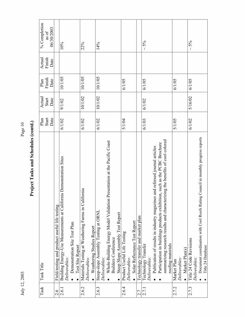
2.6
Fiel
d-te
stin
g an
d pr
oduc
t use
ful l
ife te
stin
g
2.6.
1 B
uild
ing
Ener
gy-U
se M
easu
rem
ents
at C
alifo
rnia
Dem
onst
ratio
n Si
tes
Del
iver
able
s:
• D
emon
stra
tion
Site
Tes
t Pla
n •
Test
Site
Rep
ort
6/1/
02
9/1/
02
10/1
/05
10
%
2.6.
2 M
ater
ials
Tes
ting
at W
eath
erin
g Fa
rms i
n C
alifo
rnia
D
eliv
erab
les:
•
Wea
ther
ing
Stud
ies R
epor
t
6/1/
02
10/1
/02
10/1
/05
22
%
2.6.
3 St
eep-
slop
e A
ssem
bly
Test
ing
at O
RN
L D
eliv
erab
les:
•
Who
le-B
uild
ing
Ener
gy M
odel
Val
idat
ion
Pres
enta
tion
at th
e Pa
cific
Coa
st
Bui
lder
s Con
fere
nce
• St
eep
Slop
e A
ssem
bly
Test
Rep
ort
6/1/
02
10/1
/02
10/1
/05
14
%
2.6.
4 Pr
oduc
t Use
ful L
ife T
estin
g D
eliv
erab
les:
•
Sola
r Ref
lect
ance
Tes
t Rep
ort
5/1/
04
6/
1/05
2.7
Tech
nolo
gy tr
ansf
er a
nd m
arke
t pla
n
2.
7.1
Tech
nolo
gy T
rans
fer
Del
iver
able
s:
• Pu
blic
atio
n of
resu
lts in
indu
stry
mag
azin
es a
nd re
fere
ed jo
urna
l arti
cles
•
Parti
cipa
tion
in b
uild
ings
pro
duct
s exh
ibiti
on, s
uch
as th
e PC
BC
Bro
chur
e su
mm
ariz
ing
rese
arch
resu
lts a
nd c
hara
cter
izin
g th
e be
nefit
s of c
ool c
olor
ed
roof
ing
mat
eria
ls
6/1/
03
6/1/
02
6/1/
05
~
5%
2.7.
2 M
arke
t Pla
n D
eliv
erab
les:
•
Mar
ket P
lan(
s)
5/1/
05
6/
1/05
2.7.
3 Ti
tle 2
4 C
ode
Rev
isio
ns
Del
iver
able
s:
• D
ocum
ent c
oord
inat
ion
with
Coo
l Roo
fs R
atin
g C
ounc
il in
mon
thly
pro
gres
s rep
orts
•
Title
24
Dat
abas
e
6/1/
02
5/16
/02
6/1/
05
~
5%

July
12,
200
3
Page
11
Proj
ect T
asks
and
Sch
edul
es (c
ontd
.)
Task
Ta
sk T
itle
Plan
St
art D
ate
Act
ual
Star
t D
ate
Plan
Fi
nish
D
ate
Act
ual
Fini
sh
Dat
e
% C
ompl
etio
n as
of
06/3
0/20
03
VII
C
ritic
al P
roje
ct R
evie
w(s
) D
eliv
erab
les:
•
Min
utes
of t
he C
PR m
eetin
g
XII
(C
) M
onth
ly P
rogr
ess R
epor
ts
Del
iver
able
s:
• M
onth
ly P
rogr
ess R
epor
ts
6/1/
02
6/1/
02
6/1/
05
36
% (1
3/36
)
XII
(D
) Fi
nal R
epor
t D
eliv
erab
les:
•
Fina
l Rep
ort O
utlin
e •
Fina
l Rep
ort
3/1/
05
10
/1/0
5
Fi
nal M
eetin
g D
eliv
erab
les:
•
Min
utes
of t
he C
PR m
eetin
g
10/1
5/05
10/3
1/05


A Review of Methods For the Manufacture
Of Residential Roofing Surfaces Hashem Akbari, Ronnen Levinson, and Paul Berdahl
Heat Island Group Lawrence Berkeley National Laboratory
Berkeley, CA 94720
Abstract Fiberglass roofing shingles, tiles, and metallic materials comprise over 80% (by roof area) of the California roofing market (54-58% fiberglass shingle, 8-10% concrete tile, 8-10% clay tile, 7% metal, 3% wood shake, and 3% slate). In climates with significant demand for cooling energy, increasing roof solar reflectance reduces energy consumption in mechanically cooled buildings, and improves occupant comfort in non-conditioned buildings. This report examines methods for manufacturing fiberglass shingles, concrete tiles, clay tiles, and metal roofing. We have focused on these four roofing products because they are typically colored with pigmented coatings or additives. The report also discusses innovative methods for increasing the solar reflectance of these roofing materials.
Acknowledgements This study was supported by funding from the California Energy Commission (CEC) through the U. S. Department of Energy under contract DE-AC03-76SF00098. The authors would like to acknowledge the support and guidance of the CEC project Manager Chris Scruton, as well as the contributions of our industrial partnersm including Mr. Gus Freshwater (vice president and general manager of the Elk Corp shingle manufacturing plant in Shafter, CA); Dr. Louis Hahn and Mr. Keith Tellman (both from Elk Corporation, Texas Headquarters); Dr. Christopher Gross (3M Industrial Mineral Division); Dr. Ingo Joedicke (ISP headquarter in Hagerstown MD); Mr. David Carlson (manager of ISP granule plant in Ione, CA); Mr. Steve Perry (manager of the Steelscape coil-coating plant in Rancho Cucamonga, CA); Ms. Michelle Vondran, Mr. John Marotta, and Mr. Jay Lewis (all from BASF); and Mr. Yoshihiro Suzuki (general manager and director of MCA Tile in Corona, CA).

Introduction According to Western Roofing Insulation and Siding magazine (July/August 2002), the total value of the 2002 projected residential roofing market in 14 western U.S. states (AK, AZ, CA, CO, HI, ID, MT, NV, NM, OR, TX, UT, WA, and WY ) was about $3.6 billion (B). We estimate that 40% ($1.4B) of that amount was spent in California. The lion’s share of residential roofing expenditure was for fiberglass shingle, which accounted for $1.7B, or 47% of sales. Concrete and clay roof tile made up $0.95B (27%), while wood shingle and shake, metal, and slate collectively represented another $0.55B (15%). The value of all other roofing projects was about $0.41B (11%).
We estimated roofing area market shares by assuming that roofing projects involving concrete tile, clay tile, wood shingle/shake, or slate were 50% (Estimate 1) to 100% (Estimate 2) more expensive than those using other roofing materials, such as shingle, metal, or membrane. This suggests that the roofing market area distribution is 54-58% fiberglass shingle, 8-10% concrete tile, 8-10% clay tile, 7% metal, 3% wood shake, and 3% slate (Table 1).
The functional distribution of the steep-slope roofing market (including both residential and small-commercial buildings) was about 25% new construction, 60% replacement, and 15% repair and maintenance.
In this report, we examine manufacturing methods for the fiberglass shingle, concrete tile, clay tile, and metal roofing materials that constitute over 80% (Note that the expenditure, estimate 1, and estimate 2 percentages are 81.4, 82.4, and 83.1, respectively.) of all roofing materials (by both expenditure and area). We have focused on these four roofing products because they are typically colored with pigmented coatings or additives. Table 2 briefly describes each technology.
Table 1. 2002 Project residential roofing market in the western regiona surveyed by Western Roofing (2002).
Market share by $ Market share by roofing area (%) Roofing Type
$B % Estimate 1 Estimate 2 Fiberglass Shingle 1.70 47.2 53.6 57.5 Concrete Tile 0.50 13.8 10.4 8.4 Clay Tile 0.45 12.6 9.5 7.7 Wood Shingle/Shake 0.17 4.7 3.6 2.9 Metal/Architectural 0.21 5.9 6.7 7.2 Slate 0.17 4.7 3.6 2.9 Other 0.13 3.6 4.1 4.4 SBC Modified 0.08 2.1 2.4 2.6 APP Modified 0.07 1.9 2.2 2.3 Metal/Structural 0.07 1.9 2.2 2.3 Cementatious 0.04 1.1 1.2 1.3 Organic Shingles 0.02 0.5 0.6 0.6 Total 3.6 100 100 100
a. The 14 states included in the western region are AK, AZ, CA, CO, HI, ID, MT, NV, NM, OR, TX, UT, WA, and WY.
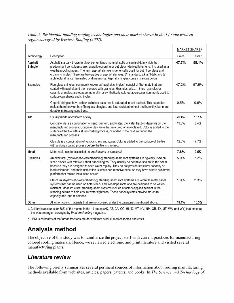
Analysis method The objective of this study was to familiarize the project staff with current practices for manufacturing colored roofing materials. Hence, we reviewed electronic and print literature and visited several manufacturing plants.
Literature review
The following briefly summarizes several pertinent sources of information about roofing manufacturing methods available from web sites, articles, papers, patents, and books. In The Science and Technology of
Table 2. Residential-building roofing technologies and their market shares in the 14-state western region surveyed by Western Roofing (2002).
MARKET SHAREa Technology Description Sales Areab
Asphalt Shingle
Asphalt is a dark brown to black cementitious material, solid or semisolid, in which the predominant constituents are naturally-occurring or petroleum-derived bitumens. It is used as a weatherproofing agent. The term asphalt shingle is generically used for both fiberglass and organic shingles. There are two grades of asphalt shingles: (1) standard, a.k.a. 3-tab, and (2) architectural, a.k.a. laminated or dimensional. Asphalt shingles come in various colors.
47.7% 58.1%
Examples Fiberglass shingles, commonly known as “asphalt shingles,” consist of fiber mats that are coated with asphalt and then covered with granules. Granules, a.k.a. mineral granules or ceramic granules, are opaque naturally- or synthetically-colored aggregates commonly used to surface cap sheets and shingles.
47.2% 57.5%
Organic shingles have a thick cellulose base that is saturated in soft asphalt. This saturation makes them heavier than fiberglass shingles, and less resistant to heat and humidity, but more durable in freezing conditions.
0.5% 0.6%
Tile Usually made of concrete or clay. 26.4% 16.1%
Concrete tile is a combination of sand, cement, and water; the water fraction depends on the manufacturing process. Concrete tiles are either air-cured or auto-claved. Color is added to the surface of the tile with a slurry coating process, or added to the mixture during the manufacturing process.
13.8% 8.4%
Clay tile is a combination of various clays and water. Color is added to the surface of the tile with a slurry coating process before the tile is kiln-fired.
12.6% 7.7%
Metal Metal roofs can be classified as architectural or structural. 7.8% 9.5%
Examples Architectural (hydrokinetic-watershedding) standing-seam roof systems are typically used on steep slopes with relatively short panel lengths. They usually do not have sealant in the seam because they are designed to shed water rapidly. They do not provide structural capacity or load resistance, and their installation is less labor-intensive because they have a solid substrate platform that makes installation easier.
5.9% 7.2%
Structural (hydrostatic-watershedding) standing-seam roof systems are versatile metal panel systems that can be used on both steep- and low-slope roofs and are designed to be water-resistant. Most structural standing-seam systems include a factory-applied sealant in the standing seams to help ensure water tightness. These panel systems provide structural capacity and load resistance.
1.9% 2.3%
Other All other roofing materials that are not covered under the categories mentioned above. 18.1% 16.3%
a. California accounts for 38% of the market in the 14 states (AK, AZ, CA, CO, HI, ID, MT, NV, NM, OR, TX, UT, WA, and WY) that make up the western region surveyed by Western Roofing magazine.
b. LBNL’s estimates of roof areas fractions are derived from product market shares and costs.

Traditional and Modern Roofing Systems, Laaly (1992) provides an overview of the production and application of various roofing materials. A website of the National Park Services (NPS 2003) also provides the historical backgrounds of several roofing materials, including asbestos-cement shingle, asphalt shingle, clay tile, composition (built-up roofing), metal, slate, and wood shingle.
The Department of Health and Human Services (DHHS 2001) and the Environmental Protection Agency (EPA 1995) have each prepared extensive documents discussing various manufacturing methods for asphalt roofing products. These focus on environmental pollution, and do not address the effects of roof reflectivity and its effects on heating and cooling energy use and on roof durability.
Brown (1960) and Jewett et al. (1994) detail the manufacture of colored roofing granules in chapters of 1960 and 1994 editions of Industrial Mineral and Rocks. Though these texts cover a wide range of technical and marketing issues related to the manufacture and production of colored granules, they provide limited information of granule coloring techniques. Joedicke (1997 and 2002) discusses this topic in greater detail.
Finally, Paris and Chusid (1997, 1999) briefly describe methods for coloring concrete products using powder, liquid, and granulated pigments. They also discuss issues related to the durability of colored concrete.
Factory visits
We visited several California facilities that produce roofing materials of interest, including a fiberglass shingle factory, a roofing granule plant, a clay roofing tile factory, and a metal coil coating plant.

Fiberglass shingle plant Elk Corporation, California Division 6200 Zerker Road, Shafter, CA 93263
On 19 February 2003, Paul Berdahl, Ronnen Levinson, and Hashem Akbari (all from LBNL), accompanied by Dr. Louis Hahn and Mr. Keith Tellman (both from Elk Corp, Texas Head Quarter), and Dr. Christopher Gross (from 3M Industrial Mineral Division), toured Elk’s shingle plant in Shafter, CA (Figure 1). The visit was hosted by Mr. Gus Freshwater, vice president and general manager.
This advanced, fully automated plant was built in 1993 and become operational in 1995. Elk buys and mixes 15 different colors of granules to produce roofing shingles in a variety of colors. At the Shafter plant, about 1200 tons of colored and 500 tons of uncolored granules are consumed each day in shingle production.
In addition to its main production line, the Shafter plant has a pilot line for limited production of special-order shingles. This pilot line may be useful when we wish to manufacture limited quantities of cool-colored roofing shingles for field testing.
The plant has a quality control laboratory to test the visual and mechanical properties of the shingles.
A virtual tour of the Elk plant is available online at <http://roofing.elkcorp.com/new_virtual_tours.cfm>.
Figure 1. Granule silos at the Elk shingle plant in Shafter, CA.

Roofing granule plant ISP Granule Products, Inc. 1900 Highway 104, P.O. Box 400 Ione, CA 95640
On 12 March 2003, Ronnen Levinson and Hashem Akbari (both from LBNL) toured the ISP Mineral Products roofing granule plant in Ione, CA (Figure 2). The visit was arranged by Dr. Ingo Joedicke (ISP Headquarters, Hagerstown, MD) and hosted by Mr. David Carlson, Ione plant manager.
ISP acquired this plant in 2002. The plant is located near rock quarries, and can make both single-coat and multi-coat products.
The plant has a quality control laboratory to test the visual and mechanical properties of the granules.
Figure 2. Roofing granule production at the ISP Mineral plant in Ione, CA.

Metal coil coating Steelscape, Inc. 11200 Arrow Route, Rancho Cucamonga, CA 91730
On 30 April 2003, Paul Berdahl, Ronnen Levinson, and Hashem Akbari (all from LBNL), accompanied by Ms. Michelle Vondran, Mr. John Marotta, and Mr. Jay Lewis (all from BASF Corporation), toured the Steelscape metal coil coating plant in Rancho Cucamonga, CA (Figure 3). The visit was arranged by Ms. Vondran, and hosted by Mr. Steve Perry, the plant shift facilitator. (BASF supplies paint for Steelscape’s coil coating operation.)
Steelscape has four major production lines: a pickle line, where hot-band metal is uncoiled, cleaned and trimmed to a desired width; a cold mill line, where the coil is thinned to a desired thickness; a metallic coating line, where the coils are recleaned, a layer of metallic coating is applied, and the surface is treated for painting or for use as a bare metal; and a paint line, where primer and finish layers are applied.
The plant has a quality control laboratory to test the visual, mechanical, and chemical properties of the color and uncolored products.
A virtual tour of the Steelscape plant is available online at <http://www.steelscape.com/aboutsteelscape/phototour.html>.
Figure 3. Steelscape metal coil coating plant in Rancho Cucamonga, CA (courtesy Steelscape 2003).

Clay roofing tile plant Maruhachi Ceramics of America, Inc. (MCA) 1985 Sampson Avenue, Corona, CA 92879
On 30 April 2003, Paul Berdahl, Ronnen Levinson, and Hashem Akbari (all from LBNL) toured the MCA clay roofing tile plant in Corona, CA (Figure 4). The visit was hosted by Mr. Yoshihiro Suzuki, general manager and director of MCA.
MCA Tile is a modern clay tile manufacturing plant that supplies tiles to the western U.S. The facility operates in two shifts—7A to 4P, and 6P to 2:30A, with the downtime used for maintenance and cleaning—and has five major operations: (1) mixing raw clay materials and preparing clay batt (dough); (2) extrusion molding of clay batt to form tiles; (3) air drying of raw tiles; (4) coloring tiles; and (5) kiln-firing colored tiles. MCA manufactures both glazed and unglazed colored tiles.
There is a quality control laboratory at the plant to test the visual and mechanical properties of the tiles. MCA has also a solar spectrum reflectometer (Devices & Services) to measure the solar reflectance of the tiles.
More information on MCA Tile products is available online at <http://www.mca-tile.com>.
Figure 4. MCA tile factory in Corona, CA (lower image courtesy MCA).

Manufacturing methods
Shingles
Colored granule production
Granules cover over 97% of the surface of a typical asphalt-soaked fiberglass shingle. Granules are applied to asphalt shingles for several reasons, including (1) UV protection; (2) coloration; (3) ballasting; (4) impact resistance; and (5) fire resistance.
Granule manufacturing plants are typically sited near a quarry of suitable base rocks. The base rocks used for manufacturing of roofing granules include andesite, coal slag, diabase, metabasalt, nephaline syenite, quartzite, rhyodacite, rhyolite, and river gravel. The essential characteristics of the base rock include (1) opacity to ultraviolet light, to protect the asphalt fiberglass from ultraviolet damage; (2) chemical and physical inertness, to provide resistance to acid rain, leaching, freeze/thaw, wet/dry cycling, oxidation and rusting; (3) low porosity, to provide good binding between the color coating and base rock, physical strength, and a low pigment requirements; (4) high temperature resistance, to withstand high firing temperatures. Other necessary characteristics include moderate hardness, to remain intact during the granule coloring process; moderate density (to weight the shingle against wind lift); uniformity, crush equidimensionally (to prevent directional embedment in the shingle manufacturing process, which changes shingle appearance); and absence of hazardous minerals.
In a roofing granule manufacturing plant, rocks blasted from quarries are crushed in several stages to reduce the rock to granule size aggregate (Figure 5). In this process, the larger aggregates are recycled to the crushing system and the smaller debris is separated for other usage. Typical roofing aggregates are about 0.5 to 2 mm in size.

Figure 5. Schematic of a granule production plant.(Figure courtesy of Jewett, C.L.,et al. 1994.)
Once the granules are milled to the right size, in a continuous process, they are mixed with a semi-ceramic color coating. The coating is a mix of color pigments in a sodium silicate, hydrated kaolin clay, and water. The preheated granules are mixed and tumbled with coating sufficient to cover the surface. The wet coated granules are then transferred to a rotary kiln where they are gradually heated to 500-1000 oF. This dehydrates and polymerizes the coating, forming an insoluble pigmented ceramic layer. The granule is then gradually cooled in a rotary cooler by sprayed water and circulated air. Finally, the pigmented granules are oiled to control dust and to improve asphalt adhesion.
The pigments used for colored granules must have certain properties, including stability at high temperature, chemical inertness, ease of dispersion, color consistency, weather stability, non-toxicity, and low cost. Primary pigments used in roofing granules include titanium dioxide (white), zinc ferrite (yellow), red iron oxides, carbon black, chrome oxide (green), and ultramarine (blue). Typically, 5-6 lb of pigment per ton of granules are required to create a single-layer coating. Multiple coatings are needed to increase pigment loading. Some granule manufacturing plants have parallel coloring lines that can be used in series to apply multiple layers of coatings on granules.
The granules (both colored and uncolored) are transported to shingle manufacturing companies by road and rail.

Shingle production
Fiberglass asphalt shingles have three major components: fiberglass mat, asphalt (with additive fillers), and granules (colored and uncolored). In a typical plant, the fiberglass mat is fed into a roller-type coater that applies layers of stabilized coating asphalt to the top and bottom surfaces of the webbing sheet. Stabilized coating asphalt is harder and more viscous than saturant asphalt, and has a higher softening point. The mineral stabilizer1 may consist of finely divided lime, silica, slate dust, dolomite, or other minerals.
The “filled” or “stabilized” coating asphalt applied by the coater is produced in the coater-mixer, which is usually positioned above the manufacturing line at the coater. Coating asphalt, typically at 400-520 °F, is piped into the mixer, and the mineral stabilizer is added. To eliminate moisture problems and to help maintain the temperature above 360 °F in the coater-mixer, the mineral stabilizer is dried and preheated before being fed into the coater-mixer.
The weight of the finished product is controlled by the amount of coating asphalt used. The coater rollers can be moved closer together to reduce the amount of coating asphalt applied to the felt, or separated to increase it. Most modern plants are equipped with automatic scales or profile scanners that monitor the sheets during the manufacturing process and warn the operator when too much or too little coating is being applied.
Colored and uncolored granules are applied in a section of the manufacturing line that usually consists of a multi-compartmented granule hopper, two parting agent hoppers, and two large press rollers. The hoppers are fed through flexible hoses from one or more machine bins above the line. These machine bins (sometimes called surge bins) provide temporary storage. The granule hopper drops colored granules from its various compartments onto the top surface of the moving sheet of coated webbing in the sequence necessary to produce the desired color pattern on the roofing.
Next, the sheet is cooled by passing it around water-cooled rollers; water may also be sprayed directly onto the sheet to speed cooling. The final steps in the production of asphalt roofing shingles are cutting and packaging. After the shingles have been cut by machine, they are moved by roller conveyor to automatic packaging equipment. The packaged shingles are then stacked on pallets and transferred by forklift to storage areas or waiting trucks.
1 The mineral stabilizer used in asphalt roofing applications is an inorganic material, typically a crushed rock. Because this material is inorganic, it is less susceptible that asphalt to temperature change and fire. These properties are important for shingle manufacturing. Asphalt with stabilizer provides uniform and consistent properties within the climatic temperature range. Essentially, the stabilizer reduces viscosity in colder weather (making the shingle less brittle) and increases viscosity in warmer weather (increasing the softening point). In addition, the mineral stabilizer decreases the flammability of asphalt, thus allowing a higher fire rating of the shingle.

(a) (b) (c)
(d) (e)
Figure 6. Shingle manufacturing processes: (a) fiberglass roll is fed into the line; (b) fiberglass enters the shingle production machinery; (c) fiberglass is soaked in asphalt and filler, then granules are roller-applied to both sides of the shingles; (d) shingle rolls are water-cooled by wet rollers; (e) cut and stacked shingles are packaged for shipping.

Figure 7. Schematic of a fiberglass shingle production plant (Figure courtesy of DHPS 2001.)

Comments
Fiberglass roofing shingles constitute a major fraction of the residential roofing market, and capsheets (granule-covered rolls of asphalt-soaked fiberglass) are commonly used on flat-roofed commercial buildings. The solar reflectance of a new shingle is predominately determined by the solar reflectance of colored granules, since its design specifies that over 97% of its surface is to be covered by granules.
There are primarily two ways to increase the solar reflectance of the granules: manufacturing granules from highly reflective (e.g., white) rocks, and/or coating the granules with reflective pigments. The use of naturally white rock is limited by local availability of suitable inert rocks, which are often not found in large quarries. Hence, manufacturers usually color the granules.
Historically, the way to produce granules with high solar reflectance has been to use a white titanium dioxide (TiO2) pigment. Since thin layers of TiO2 are transparent to light, particularly in the near-infrared (NIR) potion of the solar spectrum, multi-layer coatings are required to obtain the desired solar reflectance. For instance, IPS Mineral has developed an experimental super-white multi-coated product with a solar reflectance of about 60%. ISP A-707 Ultra-bright White that can be used for production of white roofing materials is available commercially and has a solar reflectance of 0.45–0.50.
Within the last five years, manufacturers have been experimenting with non-white, “cool color” pigments that have high reflectance in the near-infrared. However, like TiO2 pigment, cool-colored pigments typically transmit some fraction of the NIR light to the granule underneath, where it is absorbed. To increase the solar reflectance of colored granules with cool pigments, multiple layers of coatings should be applied. Obviously, with each additional layer of color coating, the cost of production increases.
One way to reduce the cost is to produce cool-colored granules in two steps (two layers). In the first step, the granule is pre-coated with a relatively inexpensive NIR-reflective pigment. In step two, the cool color pigment is applied to the pre-coated granules. This technique can be easily used in the ISP granule manufacturing plant in Ione, where they can make both single-coat and multi-coat products.
Shingles tend to lose some granules as they age and weather, exposing asphalt-coated fiberglass and reducing solar reflectance. Substituting a reflective sealant for the black asphalt could slow this degradation of solar reflectance. While developing such a replacement for asphalt may be of long-term interest, we do not see an easy solution to this problem.
It should be noted that the reflectance of an asphalt shingle covered with granules will always be less than that of the granule’s coating, since some of the light reflected by each granule strike a neighboring granule and be absorbed. These “multiple reflections” can reduce net reflectance by as much at 0.15.
Finally, the granule manufacturing and shingle manufacturing industries have designed their quality-control laboratories to test the visible color of their products. We anticipate that the industry will need to equip itself with additional instruments for test the solar reflectance and the NIR optical properties of their products. It is also envisioned that unified standards have to be developed to address issues related to manufacturing of cool-colored granules and shingles.
Clay Roof tiles
Production
Clay tile production begins by mixing and crushing various raw clay materials. For example, the raw clays used at MCA include “yellow clay” (a clay with high refraction and low plasticity), “apple clay” (a clay with low refraction and high shrinkage), and “foster clay” (a clay with high iron content to make the tile red). The raw clays are thoroughly mixed with an appropriate amount of water and aged for 4-5 days. The aging process allows the dry material to fully absorb the moisture, improving elasticity. This increases yields from the extrusion process and thus lowers the unit production cost.
Several extrusion machines and molds are employed to produce clay tiles of various shapes. The clay is de-aired by vacuum prior to extrusion. A cutter at the end of each extruder cuts the tile to desired size, and trims the tile’s edges. The wet extruded tile is then dried in a sequence of controlled drying chambers for about 24 hours. The drying process typically starts with circulating outside air at a temperature of about 20-30oC, followed by warm air at about 50oC, and then hot air at about 90oC. Drying reduces the tile’s moisture content from 15% to less than 1%. Excessively moist tiles will crack when they go through the kiln furnaces.
The dry raw tiles are inspected for defects before they are sprayed with glossy or mat glazes. The coating is basically a mixture of water, pigments, and clay additives. For the glossy finish frits, clay, and color gazed materials are added to the coating mixture. The coated tiles are stacked with a typically ½” spacers to allow an even heat distribution in the kiln. Even heating yields evenly colored tiles with good mechanical properties.
The coated tiles are then passed through a kiln and fired for 14-20 hours. The kiln has three stages: preheat, heating, and cooling. In the preheating section, the tiles are gradually heated to about 700 oC by warm air drawn from the heating section. In the heating section, the tiles are directly fired for about 4 hours by gas flame, reaching a maximum a temperature of about 1050 oC. Then the tiles are gradually cooled to about 350-400 oC by drawing outside air through the kiln.

(a) (b) (c)
(d) (e) (f)
(g) (h) (i)
(j) (k) (l)

(m) (n)
Figure 8. Clay tile manufacturing processes: (a,b) production begins by mixing and crushing raw clay components; (c,d) extrusion machines and molds produce variously shaped tiles; (e) the wet extruded tile is dried in a sequence of temperature- and humidity-controlled drying chambers for about 24 hours; (f,g,h) the dry raw tiles are inspected for defects and sprayed with glossy or mat glazes; (i) the coated tiles are stacked with spacers (typically ½” ) to allow an even heat distribution in the kiln; (j,k,l) the coated tiles are kiln-fired for 19 hours, (m) the finished tiles are shipped to customers. Figure (n) shows various tile samples.
Comments
There are three ways to improve the solar reflectance of colored tiles. The first is to ensure that the raw clay has a low concentration of light-absorbing iron and iron oxides. MCA uses magnetic separation to reduce the iron concentration of the raw clay mixture. They also use yellow clay, which is naturally low in iron-oxide.
The second method is to use cool color pigments in the glaze to provide choice of high-reflectance color. Cool pigments have been used successfully by a few leading and innovative tile-manufacturing companies. The third approach is to use cool pigments over a highly reflective undercoat. The undercoat must be allowed to properly dry before application of the topcoat.
Concrete tiles
Production
Comments

Metal roofing
The metal roofing industry may be divided into two segments: (1) coil coating plants, where raw metal coils are cleaned, thinned, primed, and coated with paint; and (2) metal forming plants, where the coated coils are either used to produce flat metal panels, or pressed into shapes that simulate non-metal roofing products (e.g., shake, slate, or tile).

Coil coating plants
Coil coaters produce rolled metals in the thickness, width, and color specified by their customers, which include but are not limited to members of the roofing industry. An advanced metal coil factory typically has four major production lines: a pickle line, where the hot-band coil is uncoiled, cleaned and side-trimmed to the customer’s specifications for width; a cold mill line, where the thickness of the coil is reduced to specifications; a metallic coating line, where the coils are cleaned again, a layer of metallic coating is applied, and the surface is treated for either painting or bare metal application; and a paint line where primer and finish coatings are applied. Although the paint line is the primary interest of this project, we will briefly review all four production lines.
PICKLE LINE
The raw material for this industry is typically a thick metal steel coil. The hot-band coil is pickled when it first arrives at the coating plant (Figure 9). There it is uncoiled and cleaned in a series of acid baths to ensure the proper surface for galvanizing (stages 1-4). The steel is then side-trimmed to the customer’s specifications for width (stage 5). At the end of the pickle line process, the steel is re-coiled and ready to go on to the cold rolling mill (stage 6). The pickle line is capable of handling two coils at a time. One coil is processed while the other is prepared to be fed to the line.
(1) Hot rolled coil. The hot-rolled coil enters the pickle line.
(2) Stitcher. The end of one coil is joined to the beginning of the next coil.
(3) Acid tank. The band of steel is run through a series of acid tanks to remove rust, then rinsed in hot water.
(4) Side trimmer. The sides of the band are trimmed to the specified width.
(5) Shear. Cuts out the stitches that connected two coils at the beginning of the line.
(6) Tension reel. Recoils the steel.
Figure 9. Metal coil coating: pickle line (courtesy Steelscape 2003).
COLD MILL LINE
In the cold reversing mill (CRM) line, the thickness of the metal coil is reduced to specification by repeatedly passing through pressure rolls (Figure 10).

(1) Cold mill entry. The metal is uncoiled and passed forward through the rollers.
(2) Entry tension reel. After its initial pass through the CRM, the coil is prepared for the next pass through the rollers. The number of passes depended on the specification for the final thickness.
(3) Main roller set. Rollers apply pressure to the steel to reduce its thickness.
(4) Delivery tension reel. The steel is recoiled.
(5) Thickness gauge.
Figure 10. Metal coil coating: cold mill line (courtesy Steelscape 2003).
METAL COATING LINE
In the metal coating line, the steel coils are cleaned again, a layer of metallic coating is applied, and the surface is treated either for painting or for use as bare metal (Figure 11). Coils from the cold mill line are fed to the system (stage 1) and welded together (stage 2) for continuous line operation. The coil then passes through an accumulator tower (stage 3) and is cleaned (stage 4) before being fed to the furnace (stage 5). The heated coil is passed through the coating pot (stage 6) where its surface is coated with zinc and aluminum amalgam. The hot-coated coil is then cooled (stage 7) and treated with a surface conditioner (stage 8) to create a smooth surface for painting. The steel is stretched for uniform flatness by the tension leveler (stage 9). The surface can also be chemically treated (stage 10) and coated with a resin (stage 11) for bare metal applications.

(1) Entry reel.
(2) Welder. The end of one coil is welded to the beginning of another for continuous operation.
(3) Entry accumulator tower.
(4) Cleaning unit. Steel is cleaned in a caustic bath, rinsed, and dried.
(5) Furnace. Steel is heated for coating application.
(6) Coating pot. Steel is coated with an amalgam of zinc and aluminum.
(7) Cooling tower. Steel is cooled to almost room temperature.
(8) Surface conditioner. Prepares the still for painting application.
(9) Tension leveler. Steel is stretched for uniform flatness.
(10) Chemical treatment. Provides interim protection against coating deterioration during storage.
(11) Resin coater. Enhances the performance of steel.
(12) Entry accumulator tower.
(13) Exit tension reel.
Figure 11. Metal coil coating: metal coating line (courtesy Steelscape 2003).
PAINT LINE
The paint line is similar to the metal coating line. In the paint line (Figure 12), a coil from the metal coating line is fed to the system (stage 1) where coils are welded together for a continuous operation of the line. Then the coil passes though an accumulator tower and cleaner (stage 2) prior to chemical coating. The chemical coater (stage 3) pre-treats the surface to accept primer, then applies primer to both side of the steel band. The primed coil is cured in an oven, then coated with the finish paint (stage 4) and cured in another oven. The cured, painted steel is then quenched with water and cooled to room temperature (stage 5). Finally, rollers remove the excess water (stage 6), and the steel goes into the exit accumulator (stage 7) before it is taken up onto an exit reel (stage 8).

(1) Entry reels.
(2) Cleaning unit.
(3) Chemical coater. Applies an initial coating on the steel.
(4) Finish coater. Coats the steel with the finish paint.
(5) Water quench. Painted steel is cooled down to room temperature.
(6) Excess water remover.
(7) Exit accumulator.
(8) Exit reel.
Figure 12. Metal coil coating: paint (courtesy Steelscape 2003).

Metal forming plants
Metal forming plants cut and press painted or unpainted metal coils to form either flat panels or simulations of non-metal roofing products (e.g., shake, shingle, tile, and slate). Some manufacturers may apply an additional layer of paint to the metal surface. Some examples of metal roofing products are shown in Figure 13.
(a) (b) (c)
(d) (e) (f)
(g) (h) (i)
(j) (k) (l)
Figure 13. Simulated roofing products made from metal: (a) Advanta Shingles; (b) Bermuda Shakes; (c) Castle Top; (d) Dutch Seam Panel; (e) Granutile; (f) Perma Shakes; (g) Scan Roof Tile; (h) Snap Seam Tile; (i) Techo Tile; (j) Verona Tile; (k) Oxford shingles; and (l) Timbercreek shakes, Products (a-j) are manufactured by ATAS International, Inc., while products (k,l) are manufactured by Classic Products, Inc.

Comments
Of all the colored roofing materials investigated in this limited study, metal roofs are most suitable for the application of cool colored coatings. The substrate (bare metal) has high initial reflectance, and is typically coated with two layers (primer + finish). If the substrate does not have high initial reflectance, use of a high-reflectance primer could reduce the cool-pigment loading required in the finish.

Summary Fiberglass roofing shingles, tiles, and metallic materials comprise over 80% (by roof area) of the western region residential roofing market. In cooling-dominated regions, increasing the solar reflectance of the roofs lowers air-conditioning use and improves comfort. The solar reflectance of new shingles is predominately determined by the solar reflectance of colored granules, since by design, over 97% of a shingle’s surface is covered with granules. To increase the solar reflectance of shingles, our primary attention should focus on roofing granules.
Until recently, the way to produce granules with high solar reflectance has been to use white TiO2 pigment. Since TiO2 in a thin layer is transparent to both visible and near-infrared (NIR) light, several layers of coating are needed to obtain the desired solar reflectance. Some manufacturers have used this technique to produce super-white products with solar reflectances exceeding 50%. Manufacturers have also tried to increase the solar reflectance of their colored products by using “cool color” pigments that offer high reflectance in the NIR. However, like TiO2, cool-colored pigments are also partly transparent to the NIR light; thus, any NIR light not reflected by the cool pigment is transmitted to the dark granule underneath, where it can be absorbed. To increase the solar reflectance of colored granules with cool pigments, multiple layers of coatings should be applied. Obviously, with each additional layer of color coating, the cost of production increases.
One way to reduce the cost is to produce cool-colored granules with a two-step, two-layer process. In the first step, the granule is pre-coated with an inexpensive pigment that is highly reflective to NIR light. In the second step, the cool-colored pigment is applied to the pre-coated granules.
For colored tiles, there are three ways to improve the solar reflectance: (1) use of raw clay materials with low concentration of iron and iron oxides; (2) use of cool pigments in the coating; and (3) application of the two-layered coloring technique using pigmented materials with high solar reflectance as an underlayer. Although all these options are in principle easy to implement, they may require changes in the current production techniques that may add to cost and competitiveness of the finished products.
Application of cool-colored pigments in metal roofing materials may require the fewest number of changes in the existing production processes. As in the cases of tile and fiberglass shingle, cool pigments can be applied to metal via a single or a double-layered technique. If the raw metal is highly reflective, a single-layered technique may suffice.
Finally, the quality-control laboratories of colored roofing manufacturers are typically equipped to test the visual appearance (e.g., color) of their products. We anticipate that the industry will need to acquire instruments for to test the solar reflectance and NIR reflectances of their products. It is also envisioned that unified standards will have to be developed to address the initial reflectance, aged reflectance, mechanical properties, and thermal properties of cool-colored roofing materials.
Acknowledgements This study was supported by funding from the California Energy Commission (CEC) through the U. S. Department of Energy under contract DE-AC03-76SF00098. The authors would like to acknowledge the support and guidance of the CEC project Manager Chris Scruton, as well as the contributions of our industrial partnersm including Mr. Gus Freshwater (vice president and general manager of the Elk Corp shingle manufacturing plant in Shafter, CA); Dr. Louis Hahn and Mr. Keith Tellman (both from Elk Corporation, Texas Headquarters); Dr. Christopher Gross (3M Industrial Mineral Division); Dr. Ingo

Joedicke (ISP headquarter in Hagerstown MD); Mr. David Carlson (manager of ISP granule plant in Ione, CA); Mr. Steve Perry (manager of the Steelscape coil-coating plant in Rancho Cucamonga, CA); Ms. Michelle Vondran, Mr. John Marotta, and Mr. Jay Lewis (all from BASF); and Mr. Yoshihiro Suzuki (general manager and director of MCA Tile in Corona, CA).
References Brown, J.A. 1960. Granules. Chapter 19 of Industrial Mineral and Rocks. Ed. J.L. Gillson. American
Institute of Mining, Metallurgical, and Petroleum Engineers. This refernce provides a detailed overview of the manufacturing methods of colored granules.
DHHS (NIOSH). 2001. Publication No. 2001-127. Asphalt fume exposure during the manufacture of asphalt roofing products. August . http://www.cdc.gov/niosh/pdfs/2001-127.pdf This document in detail describes various manufacturing methods for asphalt roofing products.
EPA. 1995. Compilation of Air Pollutant Emission Factors, AP-42, Fifth Edition, Volume I: Stationary Point and Area Sources. Chapter 11. U.S. EPA. http://www.epa.gov/ttn/chief/ap42/ch11/final/c11s02.pdf This document in detail describes various manufacturing methods and emissions from plants for asphalt roofing manufacturers.
Jewett, C.L., Collins, R.C., Weaver, L.W., and McShea, T. 1994. Roofing Granules. Chapter ?? of Industrial Mineral and Rocks (Nonmetallics other than Fuels). Senior Ed. Donald D. Carr American Institute of Mining, Metallurgical, and Petroleum Engineers. Society for Mining, Metallurgy, and Exploration, Littleton, Colo. This refernce provides a detailed overview of the manufacturing methods of colored granules.
Joedicke, I. 1997. Iron oxides in roofing granules manufacture. INTERTECH CONFERENCES. Iron Oxides 97 for Colorant & Chemical Applications. The paper discusses the production and coloring of roofing granules.
Joedicke, I. 2002. Roofing granules with a decorative metallic appearance. United States Patent Application Publications: US 2002/0187306 A1. The patent briefly discusses the colored roofing granules and methods for their preparation having decorative metallic appearance.
Laaly, H.O. 1992. The Science and Technology of Traditional and Modern Roofing Systems. Laaly Scientific Publishing, Los Angeles, CA. This book provides an overview of the production and application of various roofing materials
NPS. 2003. From asbestos to zinc, Roofing of Historic Buildings, National Park Services: http://www.cr.nps.gov/hps/tps/roofingexhibit/introduction.htm This site provides a historical background of several roofing materials including: Asbestos-Cement Shingles, Asphalt Shingles, Clay Tile, Composition (built-up roofing), Metals, Slate, and Wood Shingles.
Paris, N. and Chusid, M. 1999. Color in concrete: Beauty and Durability. (Reprint from Concrete International Magazine and the American Concrete Institute. http://www.daviscolors.com/literature/pdf/Durability.PDF The document discusses the color durability and cleaning methods.

Paris, N. and Chusid, M. 1997. Coloring systems. http://www.daviscolors.com/literature/pdf/COLORING.PDF This document briefly describes methods for coloring concrete products using powder, liquid, and granules pigments.
Steelscape. 2003. http://www.steelscape.com/aboutsteelscape/phototour.html.
Western Roofing. 2002. 2002 Market Survey. pp 62-63, July/August.
Western Roofing. 2003. Roofing Up in the West. pp 61-67, January/February.