june 16 2005 newsletter 1 - qsl.net 16 2005 newsletter.pdf · strength mat’l. 20awg 17 awg 14 awg...
TRANSCRIPT

________________________________________________________________________________________________________Moultrie Amateur Radio Klub P.O. Box 91 Lovington IL 61937
________________________________________________________________________________________________________
____________________________________________________________________Volume 3 Issue 6 June 16 2005
____________________________________________________________________
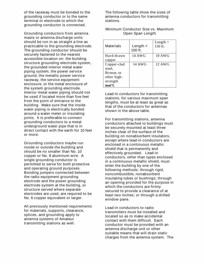
Club Tours WEIU TV Station
On May 16th the Moultrie AmateurRadio Klub toured the WEIU TVStation Studios at Eastern IllinoisUniversity
The Group was met by KevinArmstrong & Keon Rogers ,tourguides… Special THANKS to them forall their work & efforts in making thisan enjoyable tour
The group was lead into the building,shown the first of a series of soundproof rooms which were recordingstudios etc Next came the control roomwith monitor and boards
Ken then told us how they operatedetc… Next was another series of rooms which had racks of routers Continuingon we were taken to the studio wherethe actual on air programs were madewe got to examine the TV cameras Nextwas the radio room then went outsideto look at the mobile unit..
Those in this group were :N9GIF–Ron, WX9D Jerry, KA9Z Alan,WX9D XYL Gale, W9LYN Bill, N9PLBTom WC9V Ralph, Kean Rogers TourGuide, K3BY Sam, W9UFR, K9BMLJean WB9ZCN Ron WB9ZCN Son,K9SWY Vernon, KB9BWS Byron,KA9LRZ President
More photos later in this issue
PROGRAM
- - - MORE ON SATELLITES - - -
Clint Parrish–KC9S
Specifically, Clint will talk about how toset up a relatively inexpensive satellitestation and even how to work satelliteswith handhelds. He will also includemore on the new ECHO (AO-51) FMsatellite and on NOAA weathersatellites.
H F CONDITIONSSince last month’s report there have been two peaks for the Solar FluxIndex. The first reached 125 on May11th and the most recent one was up to
R F Feedback

117 on June 9th. Between those peaksthere was a valley where the flux wasin the low 80’s for about a week during the middle of May.Currently (June 14th), the SFI hasslipped to 92 and is predicted to fall to85 in a couple of days as a pair ofspots rotate off the Earth-facingportion of the Sun.
Was not very active in the last monthbut did manage to work a fewcountries, mostly on 17 meters, whenthe SFI was above 100 and the “A”Index was below 10. They includedSao Tome (S9SS), Liechtenstein(HB0/DL2SBY), Bulgaria (LZ2WO),Hong Kong (VR2XMT) and Paraguay(ZP4KFX). Having never even heardHong Kong before, it was atremendous thrill to work VR2XMT withthe 100 watts to the 17 meter verticaldipole. Do hope he will QSL! deW9LYN
QSL CARD RETURNS
With regard to W9LYN’s story last month about the 18 QSL cards that hehad sent to Europe on April 5th, he still hasreceived only the 12 cards mentioned lastmonth. He is hopeful that the remainingones will come but less so than last month.The QSL card received for his oldestcontacts this month was for a coupleof contacts with Easter Island sent on 19January 2005. Most of the remainingfive were sent 23 April or later.
LoTW
The LOGBOOK OF THE WORLD thatARRL is running and that Dave (KD9AC)told us about last year has been used forDXCC credit for more than a year now. Afair number of DXpeditions are saying thatthey will QSL via LoTW and more andmore individuals are starting to use thesystem. The last QSOs that I put in thesystem was nearly a year ago. Since thefirst of the year,I have had more than three dozen ofthose confirmed, that is QSLd for a
total of 228 QSLs out of 1,351 QSOsthat I have entered or nearly 17%.However, the total numbers in thesystem do not look as good. Thereare 3.3 million QSLs but 73.5 millionQSOs in the system or under 5%.Perhaps the percentage difference isdue to the fact that a fair number of mysubmissions were for relatively“domestic contests” likesweepstakesand the ARRL 160 meter contest whereUS and Canadian hams where makingsubmissions.
One of my last QSLs in the systemwas submitted May 30th 2005 for a CWcontact in the 2003 CQ WW CWContest by JA3JBK so it is good to seeoverseas hams beginning toparticipate in LoTW. Then too it wasgreat to be able to use a 15 metercontact with Saudi Arabia QSLd in thesystem for my 150th entity on that bandin my recent DXCC submission atDayton.de W9LYN
The NEC and UBy Jerome Buie KB4POA and Art
Varga WA9LXT
Ever wonder what the National FireProtection Association has to sayabout your amateur radio station? TheNFPA is the body that developed theNational Electric Code(NEC). Theprimary purpose of the NEC is to setstandards which promote safety. Itdoes not provide constructionmethods or practices. The code isintentionally written to allow flexibilityin the implementation. Local buildingauthorities in most states haveadopted the NEC as requirements forconstruction standards. Thesestandards have become the law andmust be observed. Some jurisdictionshave made additions and modificationsto the NEC to suit special localconditions. However, this article willonly address NFPA code and not anyunique local requirements.

Enforcement of these regulations isnormally performed when a building isbeing constructed or major changesare required. Unless you are building anew home you may never have tocomply with the codes. However, foryou and your family’s safety, it would be prudent to maintain compliancewith the NEC as you build your station.
Any wiring changes you make to yourhouse to accommodate your stationshould be made in accordance with thesections of the code that relate toresidential wiring. Article 810 of thecode applies directly to receiving andtransmitting stations. It also refers toany radio noise suppressors that areconnected to power-supply leads; theymust be listed. This means they willhave a stamp stating that they complywith NEC requirements and you mustprotect them from physical damage.
Wire antennas and lead-in conductorsmust be made of hard-drawn copper,bronze, aluminum alloy, copper-cladsteel, or other high-strength,corrosion-resistant materials. Soft ormedium-drawn copper is onlypermitted for lead-in conductors wherethe maximum span between supportsis less than 35 feet. Antennas and lead-in conductors must be securelysupported and must not be attached tothe electric service mast. Don’t connect them to poles, or similarstructures carrying open electric light,power wires, or trolley wires. Makesure that all insulators used to supportantennas and lead-in wires havesufficient mechanical strength to safelysupport the conductors. Lead-inconductors must be securely attachedto the antennas.
Antennas and lead-in conductors fromantennas to a building must not crossover open conductors of electric lightor power circuits, and must be keptwell away from all such circuits toavoid the possibility of accidentalcontact. Where proximity to
conductors cannot be avoided, theinstallation must provide a clearance ofat least two feet. When possible,antenna conductors should beinstalled so as not to cross under openelectric light or power conductors.
Splices and joints in antenna spansmust be mechanically secured withapproved splicing devices or by othermeans that will not appreciably weakenthe conductors. Masts and metalstructures supporting antennas mustbe grounded in accordance withSection 810-21.
The physical aspects of antennaconductors and self-supportingantennas for receiving stations andtransmitting stations are similar, buttransmitting stations have additionalrequirements that will be covered later.The conductor sizes for receivingstations are as follows.
Minimum Conductor Size vs.Maximum Open Span Length
Materials Length< 35 ft
Length35–150ft.
Length> 150 ft.
Aluminumalloy,hard-drawncopper
19AWG
14AWG 12AWG
Copper-clad steel,Bronze, orother high-strengthmat’l.
20AWG17
AWG14
AWG
Self-supporting antennas, such asvertical rods, dishes, or dipolestructures must be made of corrosion-resistant materials and of strengthsuitable to withstand ice and windloading conditions. They must belocated well away from overheadconductors of electric light and powerlines to avoid the possibility of theantenna or structure falling into ormaking accidental contact.
Lead-in conductors from receivingantennas must have a tensile strengthat least as great as that of theconductors for the antennas asspecified in the table above. Lead-insconsisting of two or more conductorsthat are twisted together, enclosed inthe same covering, or are concentric;the combination will be at least asgreat in size and have tensile strengthas that of the conductors specified inthe above table.
Lead-in conductors from receivingantennas that are attached to buildingsmust be installed so that they cannotswing closer than two feet to theconductors of circuits of 250 volts orless, or 10 feet to the conductors ofcircuits of over 250 volts. In the caseof circuits not more than 150 voltsbetween conductors, where allconductors involved are supported toensure permanent separation, thenminimum permitted clearance may bereduced to not less than four inches.
Clearance between lead-in conductorsand any part of a lightning rod systemshall not be less than six feet.Underground lead-in conductors mustbe separated from any light or powercircuits by at least 12 inches.
Indoor antennas and lead-ins must notbe run nearer than 2 inches toconductors of other wiring systems inthe premises, except where such otherconductors are in metal raceways orcable armor, or where permanentlyseparated from such other conductorsby a continuous and firmly fixednonconductor, such as porcelain tubesor flexible tubing. Indoor antennas andindoor lead-ins are permitted to occupythe same box or enclosure withconductors of other wiring systemswhere separated from the otherconductors by an effectivepermanently installed barrier. The useof electric supply circuits for receivingantennas is permitted in Section 810-19providing that the receiver isconnected via a listed device.
Antenna discharge units are requiredfor receiving stations. Each conductorof a lead-in from an outdoor antennamust be provided with a listed antennadischarge unit, except where the lead-in conductors are enclosed in acontinuous metallic shield that is eitherpermanently and effectively grounded,or is protected by an antennadischarge unit. Antenna dischargeunits must be located outside thebuilding or inside the building betweenthe point of entrance of the lead-in andthe radio set or transformers, and asnear as practicable to the entrance ofthe conductors to the building. Theantenna discharge unit must not belocated near combustible material norin any hazardous location whereignitable vapors and gases, dust, andvolatile flammable liquids may bepresent. Antenna discharge unitsmust be grounded in accordance withSection 810-21.
Grounding conductors may be made ofcopper, aluminum, copper-clad steel,bronze, or similar corrosion-resistantmaterial. Aluminum or copper-cladaluminum grounding conductorsshould not be used where there isdirect contact with the earth, masonry,or other corrosive conditions.Aluminum or copper-clad aluminumshould not be installed within 18inches of the earth. Insulation ongrounding conductors is not requiredby the NEC.
Grounding conductors must besecurely fastened in place and may bedirectly attached without the use ofinsulating supports. Where propersupport cannot be provided, the size ofgrounding conductors may beincreased so they become self-supporting. Mechanical protectionmust be provided for exposedgrounding conductors to protect themfrom physical damage. The size of theconductor may be increased tocompensate for lack of protection.When grounding conductors are run ina metal conduit or raceway, both ends
of the raceway must be bonded to thegrounding conductor or to the sameterminal or electrode to which thegrounding conductor is connected.
Grounding conductors from antennamasts or antenna discharge unitsshould be run in as straight a line aspracticable to the grounding electrode.The grounding conductor should besecurely fastened to the nearestaccessible location on: the buildingstructure grounding electrode system,the grounded interior metal waterpiping system, the power serviceground, the metallic power serviceraceway, the service equipmentenclosure, or the metal enclosure ofthe system grounding electrode.Interior metal water piping should notbe used if located more than five feetfrom the point of entrance to thebuilding. Make sure that the insidewater piping is electrically bondedaround a water meter or insulatingjoints. It is preferable to connectgrounding conductors to a metalunderground water pipe that is indirect contact with the earth for 10 feetor more.
Grounding conductors maybe runinside or outside the building andshould be no smaller than No. 10copper or No. 8 aluminum wire. Asingle grounding conductor ispermitted to serve for both protectiveand operating ground purposes.Bonding jumpers connected betweenthe radio equipment groundingelectrode and the power groundingelectrode system at the building, orstructure served where separateelectrodes are used, are required to beNo. 6 copper equivalent or larger.
All previously mentioned requirementsfor materials, supports, clearance,splices, and grounding apply toantenna systems of Amateurtransmitting stations as well.
The following table show the sizes ofantenna conductors for transmittingstations.
Minimum Conductor Size vs. MaximumOpen Span Length
Materials Length <150 ft.
Length >150 ft.
Hard-drawncopper
14 AWG 10 AWG
Copper-cladsteel,Bronze, orother high-strengthmat’l.
14 AWG 12 AWG
Lead-in conductors for transmittingstations, for various maximum spanlengths, must be at least as great asthat of the conductors for antennasshown in the above table.
For transmitting stations, antennaconductors attached to buildings mustbe securely mounted at least threeinches clear of the surface of thebuilding on nonabsorbent insulators,except where lead-in conductors areenclosed in a continuous metallicshield that is permanently andeffectively grounded. Lead-inconductors, other than types enclosedin a continuous metallic shield, mustenter the building by one of thefollowing methods: through rigid,noncombustible, nonabsorbentinsulating tubes or bushings; throughan opening provided for the purpose inwhich the conductors are firmlysecured to provide a clearance of atleast two inches; or through a drilledwindow pane.
Lead-in conductors to radiotransmitters must be installed andlocated so as to make accidentalcontact with them difficult. Eachconductor must be provided with anantenna discharge unit or othersuitable means that will drain staticcharges from the antenna system. The

NEC provides exceptions for lead-insthat are protected by a continuousmetallic shield that is permanentlygrounded and where the antenna ispermanently and effectively grounded.
The minimum size of protectivegrounding conductors for transmittingstations should no smaller than No. 10copper, bronze, or copper-clad steelwire. Remember, this is for safetyonly. The NEC states that the size ofthe operating grounding conductormust not be less than No. 14 copperwire or its equivalent. In practicehowever, an operating groundconductor may need to be much larger.
Interior installations for transmittingstations require that all conductorsinside the building must be separatedat least four inches from theconductors of an electric light, power,or signaling circuits. Transmittersmust be enclosed in a metal frame orgrille, or separated from the operatingspace by a barrier or other equivalentmeans, and all metallic parts of theenclosure must be connected toground. All external metal handles andcontrols accessible to the operatingpersonnel must be grounded. Allaccess doors must be provided withinter-locks that will disconnect allvoltages over 350 volts betweenconductors when any access door isopened.
Compliance with the NEC does notguarantee that your station is totallyprotected against lightning strikes, butit is a good beginning point forbuilding a safe and effective station.
For more information on stationgrounding and lightning protection, wesuggest reading “Lightning Protection for the Amateur Station,” written by Ron Block, KB2UYT. This three-partarticle was published in the June, July,and August 2002 issues of QSTmagazine. During thunderstorms, youstill may wish to disconnect yourantenna system. The April 2002 issueof QST features a handy lightning
detector device, designed by BobRadmore, N2PWP. It provides awarning that could protect you andyour station from early expiration.
--------------------IDEAS FOR M.A.R.K. PROGRAMS
Would greatly appreciate yoursuggestions for programs for the clubmeetings. If you have something youwould like to present, or know a personwho could give us a good programplease let me know. .... de W9LYN<[email protected]
FOR SALEYaesu VX-2R Dual band handheld w/two antennas, spk/mic, and allmanuals. 85.00Ron N9GIF
I have a complete ham station I wouldlike to sell. I thought I'd drop you a linein case any of your club membersmight be interested. Here is the list:Yaesu FT-757 GX All mode HFtransceiver Icom IC-3200A Dual bandFM transceiver (needs repair; squelchdoesn't work)Icom IC-27A 2m. FM transceiverMFJ Deluxe Versa Tuner II antennatuner Trippelite Mod. PR-40A 40 amp.regulated power supplyCushcraft AR-270 Dual Band (70 cm /2m.) Ringo antenna Hy-Gain Omni DX-88 eight-band vertical antennaAll manuals and original boxesPackage price: all for $550Nick Stokes (KA9FTW)1107 N. 19th St.Mattoon, IL. 61938 [email protected]
Kenwood 520 F with manualPaul K9COB
From the Editor's DeskAnyone having news events oractivities for this newsletter Pleasecontact me [email protected] KA9LRZ–Editor
AnnouncementsHam Radio Breakfast- Every Fridaymorning Amateurs meet at D & W

Restaurant in Mattoon at 8 am Allamateurs are welcome
Coles County ARES will meet Fridaysat the Forum from 6:30 AM to about7:10 AM until further notice. This islocated about four doors East of theold Gowin’s restaurant site in Mattoon...
Don't forget to check into the ClarkCounty ARES Net Wed nights at 9:00pm on 146.520 N9YRX NCS
APRS Net following the ARES net 9:30pm APRS will be on 144.390 Will use146.520 Simplex to coordinate thingsuntil established Use N9YRX-3 tocheck in N9YRX
WEEKLY M.A.R.K. NETS
Every Saturday Night ten meters net at8 pm on 28400 USB Ken KA9AHP NCS
Every Sunday Night 8 pm MoultrieAmateur Radio Klub net 146.655 Tone162.2 Bob KA9LRZ NCS
OFFICERSPresident Bob OlsonKA9LRZ
Vice President Bill JamesW9LYN
Treasurer Alan Dickens KA9Z
Secretary Robert (Bob )WestW9UFR
TRUSTEESRalph Zancha
WC9V Term Ends September 2005
Ron AmexN9GIF Term Ends September 2006
Byron AbramsKB9BWS Term Ends September 2007
CORRESPONDENCE & DUES
SEND TO: Moultrie Amateur RadioKlub
P. O. Box 91Lovington, IL 61937
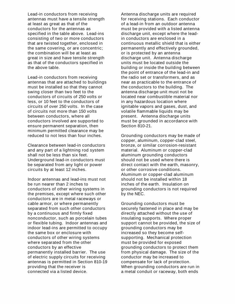
Group Dinner at AirportPhotos by Alan KA9Z
Thanks Alan
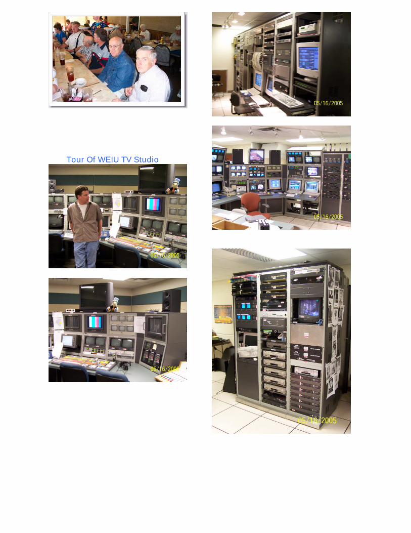
Tour Of WEIU TV Studio
