junior v3 maintenance manual - fire and security … · global status zones queue review faults...
TRANSCRIPT
G L O B A L
STATUS QUEUE REVIEWZONES
FAULTS KEYPAD CONTROLS DISABLEMENTS
FIRE
FAULT
PRE-ALARM
TEST
DISABLED
SYSTEM ON
ALARM FAULT
SUPPLY FAULT
SYSTEM FAULT
ENTERESC
DELAYS
ACTIVE
SELECTED
DETECTORS
SOUNDERS
DISABLE
AUXILIARY
RELAYS
SOUNDERS
ACTIVATE/ SILENCE
SYSTEM RESET
LAMP TEST
BUZZER
SILENCE
DISABLED
TEST
FAULT
FIRE1 2 3 4 5 6 7 8
MANUFACTURED IN THE E.U. TO THE
REQUIREMENTS OF EN54 Pt 2 & Pt 4 1999
F I R E E Q U I P M E N T
REVISION 2.3SEPTEMBER 17, 2005
JUNIOR V3Fire Alarm Control Panel
OPERATION
&
MAINTENANCE
MANUAL
CONTENTS
SECTION 1 -
1.1 Description of the fire control panel fascia................................................
1.2 Alarm.................................................................................................
1.9 Caretaker Test Mode.............................................................................
1.10 Disablements......................................................................................
1.10.1 Selected detectors..............................................................
2.1 SIM CARD replacement.......................................................................
2.2 Electrical Mains fuse.............................................................................
2.3 Battery voltage and charger checks.........................................................
2.4 Use of programming functions for maintenance.......................................
2.5 Getting into Programming Mode............................................................
2.6 Logbook.............................................................................................
2.7 Event data sheet...................................................................................
OPERATION
1.3 Reset the system...................................................................................
1.4 Sound and silence the alarms.................................................................
1.5 Read the Fire, Fault, Test and Disabled queues..........................................
1.6 Active Delays.......................................................................................
1.7 Lamp Test............................................................................................
1.8 Perform a fire drill.................................................................................
1.10.2 Sounders Disable...............................................................
1.10.3 Auxiliary Relays..................................................................
1.10.4 Enable/Disable Zones.........................................................
1.11 If the panel displays a fault.....................................................................
1.12 If the panel displays a pre-alarm............................................................
SECTION 2 - MAINTENANCE
2
4
5
5
6
7
8
9
10
12
12
13
13
14
14
14
15
1616
16
18
19
20
G LO B A LF I R E E Q U I P M E N T
1JUNIOR V3 - OPERATION & MAINTENANCE MANUAL - REVISION 2.3 - 17-SEP-2005
Some functions are only available at Authorized User level of Access. To enter this mode, a valid user
Code has to be entered using the panel's front display keypad. The factory default code is:
To enter, press ENTER then press 5 consecutive , then press ENTER again. If code
entry was successful, the words " USER ACCESS LEVEL" will appear on the top line of the LCD display.
�����
�����
NOTE: Functions indicated as available to the General User do not require an access code to be entered.

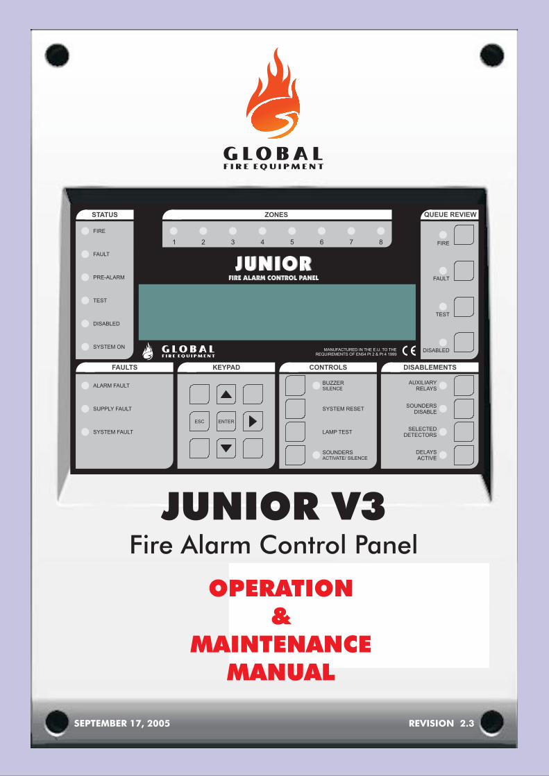
1.1 DESCRIPTION OF THE FIRE CONTROL PANEL FASCIA
FIRE
FAULT
PRE-ALARM
TEST
DISABLED
SYSTEM ON
ALARM FAULT
: If the LED is RED it indicates that there is a fire situation.
: If the LED is AMBER it indicates a fault situation. Additional information will be shown on the LCD displayand, if applicable, on the LEDs in the FAULTS section of the main panel (i.e. 7, 8, 9, 10).
: If the LED is AMBER it indicates that a detector is in PRE-ALARM.
: If the LED is AMBER it indicates that the panel is in a test mode.
: If the LED is AMBER it indicates that at least one disablement exists.
: If the LED is GREEN it means that the panel is in ACTIVE mode. If the LED is flashing GREEN then thepanel is in INSTALLATION mode.
: If the LED is AMBER it indicates that there is a problem with a loop sounder or conventional soundercircuit. This could be an open or short circuit.
: If the LED is AMBER it indicates that there is a Primary Supply (Electrical mains) Fault, a Battery Faultor that there is an Earth Fault.
: If the LED is AMBER it indicates that there is 5 Volt fault or a processor/program failure.
: Fire Zone indicator LEDs
SUPPLY FAULT
SYSTEM FAULT
ZONES
1
2
3
4
5
6
7
8
9
10
OPERATIONSECTION 1
2
STATUS QUEUE REVIEWZONES
FAULTS KEYPAD CONTROLS DISABLEMENTS
FIRE
FAULT
PRE-ALARM
TEST
DISABLED
SYSTEM ON
ALARM FAULT
SUPPLY FAULT
SYSTEM FAULT
ENTERESC
DELAYS
ACTIVE
SELECTED
DETECTORS
SOUNDERS
DISABLE
AUXILIARY
RELAYS
SOUNDERS
ACTIVATE/ SILENCE
SYSTEM RESET
LAMP TEST
BUZZER
SILENCE
DISABLED
TEST
FAULT
FIRE1 2 3 4 5 6 7 8
MANUFACTURED IN THE E.U. TO THE
REQUIREMENTS OF EN54 Pt 2 & Pt 4 1999
1
2
3
4
5
6
7
8
9
10
1213
14
15
1617
11
1819
21
2322
20
2524
2726
29
30
3233
31
28
JUNIOR V3 - OPERATION & MAINTENANCE MANUAL - REVISION 2.3 - 17-SEP-2005
G L O B A LF I R E E Q U I P M E N T

KEYPAD
BUZZER SILENCE
BUZZER SILENCE
SYSTEM RESET
LAMP TEST
SOUNDERS ACTIVATE/SILENCE.
SOUNDERS ACTIVATE/SILENCE
DELAYS ACTIVE
DELAYS ACTIVE:
SELECTED DETECTORS
SELECTED DETECTORS
SOUNDERS DISABLE:
SOUNDERS DISABLE:
AUXILIARY RELAYS
AUXILIARY RELAYS
DISABLED
DISABLED
TEST
TEST
FAULT
FAULT
FIRE
FIRE
NOTE: The functions of some switches will only be operational after entering the authorized user orprogramming access codes.
Press these buttons to toggle between menus, enter User and programming codes and other on-screeninformation.
: Pressing this button will silence the internal buzzer during a FIRE or FAULT condition.
: If the LED is lit, it indicates that a new FAULT or FIRE condition has occurred.
: Pressing this button restores the panel to its normal operating condition after an alarm. Alarms mustbe silenced before a SYSTEM RESET can be performed. A SYSTEM RESET does not clear any settings or disablements;it only clears FIRE and FAULT conditions (and then only if the source of the FIRE or FAULT has been cleared).
: Whilst this button is depressed all of the panel’s LEDs will be illuminated and all of the LCD display pixelswill be set to black. Use this button to confirm the LEDs and LCD display are functional.
: Pressing this button will activate all sounders and panel buzzers (main panel andRepeaters). Pressing the button again will silence the sounders
: If the LED is RED it means that the SOUND ALARMS function has been activatedby either pressing SOUNDERS ACTIVATE/SILENCE switch or during an alarm or Evacuate function is active.
: Delays can be configured for the sounders and I/O modules using the programming functions.Pressing this button enables or disables these delays.
If the LED is AMBER it means that the delays are active.
: Using the programming functions individual detectors can be set for SELECTIVEDISABLEMENT. When this button is activated those detectors will be disabled (isolated). Note that this button will onlyoperate if at least one detector has been set for SELECTIVE DISABLEMENT.
: If the LED is AMBER it means that the selected detectors are isolated.
Pressing this button will enable/disable all sounders in the system.
This LED will be lit when sounders are disabled
: Pressing this switch disables or enables all the relay and I/O module outputs.
: If the LED is lit it means that the relay and I/O module outputs are disabled.
: If there are disablements then pressing this button will show the disablements on the LCD display. If thereare more disablements than can be shown on the LCD display at one time then subsequent presses of this button willstep through all the disablements.
: If the LED is AMBER it means that there is at least one disablement.
: If there are ZONES in test mode then pressing this button will show those ZONES on the LCD display. If moreZONES are in test mode than can be shown on the LCD display at one time then subsequent presses of the button willstep through all the ZONES in test mode.
: If the LED is AMBER it means that one or more ZONES are in test mode.
: If there is more than one FAULT, or if there is at least one FAULT and a FIRE, pressing this button will displaythe next FAULT report on the LCD display for 20 seconds. Subsequent presses will step through all the FAULT reports.
: If the LED is flashing AMBER it means that are FAULT reports to be reviewed. If the LED is steady AMBER thenall FAULT reports have been reviewed.
: If there is more than one FIRE pressing this button will display the next FIRE report on the LCD display for 20seconds. Subsequent presses will step through all the FIRE reports.
: If the LED is flashing RED it means that there are FIRE reports to be reviewed. If the LED is steady RED then allFIRE reports have been reviewed.
:11
12
13
14
15
16
17
18
19
20
21
22
23
24
25
26
27
28
29
30
31
32
33
OPERATION
1.1 DESCRIPTION OF THE FIRE CONTROL PANEL FASCIA (continued...)
G LO B A LF I R E E Q U I P M E N T
JUNiOr
3JUNIOR V3 - OPERATION & MAINTENANCE MANUAL - REVISION 2.3 - 17-SEP-2005

STATUS QUEUE REVIEWZONES
FAULTS KEYPAD CONTROLS DISABLEMENTS
FIRE
FAULT
PRE-ALARM
TEST
DISABLED
SYSTEM ON
ALARM FAULT
SUPPLY FAULT
SYSTEM FAULT
ENTERESC
DELAYS
ACTIVE
SELECTED
DETECTORS
SOUNDERS
DISABLE
AUXILIARY
RELAYS
SOUNDERS
ACTIVATE/ SILENCE
SYSTEM RESET
LAMP TEST
BUZZER
SILENCE
DISABLED
TEST
FAULT
FIRE1 2 3 4 5 6 7 8
MANUFACTURED IN THE E.U. TO THE
REQUIREMENTS OF EN54 Pt 2 & Pt 4 1999
To do this press the BUZZER SILENCE.
Pressing this button will:
Silence the internal buzzerturn off BUZZER SILENCE
To stop Sounders, press SOUNDERACTIVATE/SILENCE button. The LED willalso turn off after pressing.
The STATUS - FIRE will remain lit RED.
button
LED
LED
�
�
At the fire controlpanel, the STATUS -F I R E w i l lilluminate RED.
The fire controlpanel buzzer willsound continuously.
The location of thealarm (or alarms)will be shown on thefire control panel
L E D
LCD display.
1.2 ALARM (Authorised User Access)
If the fire alarm control panel signals an ALARM the following events will take place:
The sounders, I/O modules and other outputs will operate in accordance with their programming.
EVACUATE IN ACCORDANCE WITH THE SITE PROCEDURE
ONLY WHEN AUTHORISED should you silence the alarms.
DO NOT PRESS UNTIL THE ALARM CONDITION HAS BEEN DEALT WITH.SYSTEM RESET
OPERATIONG LO B A LF I R E E Q U I P M E N T
JUNiOr
4JUNIOR V3 - OPERATION & MAINTENANCE MANUAL - REVISION 2.3 - 17-SEP-2005
The BUZZER SILENCELED will be illuminated.
The SOUNDERSACTIVATE/SILENCELED will be illuminated.
If more than onealarm has occurredthe QUEUE REVIEWFIRE willRED indicating thatfurther fire reportscan be displayed onthe LCD display bypressing the QUEUEREVIEW FIRE .
LED
button
flash
The external RED Zone LEDs will be illuminated forthe Zones in FIRE.

STATUS QUEUE REVIEWZONES
FAULTS KEYPAD CONTROLS DISABLEMENTS
FIRE
FAULT
PRE-ALARM
TEST
DISABLED
SYSTEM ON
ALARM FAULT
SUPPLY FAULT
SYSTEM FAULT
ENTERESC
DELAYS
ACTIVE
SELECTED
DETECTORS
SOUNDERS
DISABLE
AUXILIARY
RELAYS
SYSTEM RESET
LAMP TEST
BUZZER
SILENCE
DISABLED
TEST
FAULT
FIRE1 2 3 4 5 6 7 8
MANUFACTURED IN THE E.U. TO THE
REQUIREMENTS OF EN54 Pt 2 & Pt 4 1999
STATUS QUEUE REVIEWZONES
FAULTS KEYPAD CONTROLS DISABLEMENTS
FIRE
FAULT
PRE-ALARM
TEST
DISABLED
SYSTEM ON
ALARM FAULT
SUPPLY FAULT
SYSTEM FAULT
ENTERESC
DELAYS
ACTIVE
SELECTED
DETECTORS
SOUNDERS
DISABLE
AUXILIARY
RELAYS
SOUNDERS
ACTIVATE/ SILENCE
SYSTEM RESET
LAMP TEST
BUZZER
SILENCE
DISABLED
TEST
FAULT
FIRE1 2 3 4 5 6 7 8
MANUFACTURED IN THE E.U. TO THE
REQUIREMENTS OF EN54 Pt 2 & Pt 4 1999
On the fire control panel:
Press the
All sounders turn onThe SOUNDERS
illuminates REDTo stop sounders, press
again
button.
LED
�
�
�
ACTIVATE/SILENCE
� The LED
extinguishes
SOUNDERS
SOUNDERS
SOUNDERS
ACTIVATE/SILENCE
ACTIVATE/SILENCE
ACTIVATE/SILENCE
button
1.4 SOUND AND SILENCE THE ALARMS (EVACUATION) )(Authorised User Access)
This section shows you how to turn on and turn off all the sounders in an installation. It is identical to a firedrill procedure.
This procedure should be used if:
There has been an alarm and the alarmcondition no longer exists.
There has been a fault and the faultcondition no longer exists.
After entering either the User or programmingAccess Code, press the button.The system takes about 20 seconds to reset. Thecompany name, date and time will appear onthe LCD display when the reset is complete.
Any alarm and/or fault LEDs indicated by thepanel before pressing will nolonger be illuminated after reset.
A SYSTEM RESET can only be performed once allalarms have been silenced.
�
�
SYSTEM RESET
SYSTEM RESET
OPERATION
1.3 RESET THE SYSTEM (Authorised User Access)
G LO B A LF I R E E Q U I P M E N T
JUNiOr
5JUNIOR V3 - OPERATION & MAINTENANCE MANUAL - REVISION 2.3 - 17-SEP-2005
SOUNDERS
ACTIVATE/ SILENCE

STATUS QUEUE REVIEWZONES
FAULTS KEYPAD CONTROLS DISABLEMENTS
FIRE
FAULT
PRE-ALARM
TEST
DISABLED
SYSTEM ON
ALARM FAULT
SUPPLY FAULT
SYSTEM FAULT
ENTERESC
DELAYS
ACTIVE
SELECTED
DETECTORS
SOUNDERS
DISABLE
AUXILIARY
RELAYS
SOUNDERS
ACTIVATE/ SILENCE
SYSTEM RESET
LAMP TEST
BUZZER
SILENCE
DISABLED
TEST
FAULT
FIRE1 2 3 4 5 6 7 8
MANUFACTURED IN THE E.U. TO THE
REQUIREMENTS OF EN54 Pt 2 & Pt 4 1999
OPERATION
1.5 READ THE FIRE, FAULT, TEST AND DISABLED QUEUES(Access level 1 - General User)
Fire, fault, test, and disabled messages are shown on the LCD display.
The LCD has a limited display area. If more messages exist than can be shown on the LCD display theFIRE, FAULT, TEST or DISABLED LEDs illuminate on the QUEUE REVIEW area of the fascia. The followingprocedure describes how to display the additional messages.
If the QUEUE REVIEW - FIRE is flashing RED....
Press the QUEUE REVIEW - FIRE to display the first queued message.Press the button again to review the next queued message. Do this until allmessages have been reviewed. The LED stops flashing RED, but remains lit,once all messages have been displayed.
After 20 seconds the first fire event will be re-displayed.
LED
button
If the QUEUE REVIEW - FAULT is flashing AMBER....
Press the QUEUE REVIEW - FAULT
The LED illuminates steady AMBER when allmessages have been displayed.
After 20 seconds the first fault will be re-displayed unless a fire has occurred inwhich case the first fire will be re-displayed instead.
LED
button to display the first queued message.Press the button again to review the next queued message. Do this until allmessages have been reviewed.
If the QUEUE REVIEW - TEST is illuminated AMBER....
Press the QUEUE REVIEW - TEST to display the Zones in test mode.Sometimes not all the Zones in test mode can be displayed at once, in this casepress the button again to see the next set of Zones in test mode.
After 15 seconds the display will return to it’s quiescent state (usually thecompany name and current time).
LED
button
If the QUEUE REVIEW -DISABLED is illuminated AMBER....
Press the QUEUE REVIEW -DISABLED to display the disablements onthe LCD.
LED
buttonSometimes not all the disablements can be displayed at once, in this
case press the button again to see the next set of disablements.
After 15 seconds the display will return to it’s quiescent state (usually thecompany name and current time).
TEST
DISABLED
G LO B A LF I R E E Q U I P M E N T
JUNiOr
FIRE
FAULT
6JUNIOR V3 - OPERATION & MAINTENANCE MANUAL - REVISION 2.3 - 17-SEP-2005

STATUS QUEUE REVIEWZONES
FAULTS KEYPAD CONTROLS DISABLEMENTS
FIRE
FAULT
PRE-ALARM
TEST
DISABLED
SYSTEM ON
ALARM FAULT
SUPPLY FAULT
SYSTEM FAULT
ENTERESC
DELAYS
ACTIVE
SELECTED
DETECTORS
SOUNDERS
DISABLE
AUXILIARY
RELAYS
SOUNDERS
ACTIVATE/ SILENCE
SYSTEM RESET
LAMP TEST
BUZZER
SILENCE
DISABLED
TEST
FAULT
FIRE1 2 3 4 5 6 7 8
MANUFACTURED IN THE E.U. TO THE
REQUIREMENTS OF EN54 Pt 2 & Pt 4 1999
OPERATION
1.6 DELAYS ACTIVE - (Authorised User Access)
During installation, via the programming functions, delays can be set for the sounders and I/O modules.
These delays are only active when the ACTIVE LED is illuminated. At all other times the soundersand I/O modules will operate immediately a fire is detected.
o enable or disable these delays press the S button.
Note that it is also possible, via the programming functions, to set to automatically turn offat night.
DELAYS
After entering User Access code, t DELAYS ACTIVE
DELAYS ACTIVE
For details on the programmable features and delays refer to the ‘Installation & Commissioning Manual’.
During an alarm condition, if the delays are active (DELAYS ACTIVE LED is lit), pressing the DELAYS ACTIVEbutton will cancel the delays and every sounder programmed to be activated during a specific fire alarmcondition will activate immediately.
G LO B A LF I R E E Q U I P M E N T
JUNiOr
7JUNIOR V3 - OPERATION & MAINTENANCE MANUAL - REVISION 2.3 - 17-SEP-2005

Press and hold the LAMP TEST .
All LEDs shown in this diagram should be illuminated
All pixels on the LCD display should turn black
All external Zone LEDs should be illuminated
Release the LAMP TEST button to end the test. The LEDs and LCD display will return to their normalcondition.
button
�
�
�
OPERATION
1.7 LAMP TEST - (General User Access)
This tests that all LEDs on the fascia are functioning, that the buzzer sounds properly and that the LCDdisplay is fully functional.
G LO B A LF I R E E Q U I P M E N T
JUNiOr
8JUNIOR V3 - OPERATION & MAINTENANCE MANUAL - REVISION 2.3 - 17-SEP-2005
STATUS QUEUE REVIEWZONES
FAULTS KEYPAD CONTROLS DISABLEMENTS
FIRE
FAULT
PRE-ALARM
TEST
DISABLED
SYSTEM ON
ALARM FAULT
SUPPLY FAULT
SYSTEM FAULT
ENTERESC
DELAYS
ACTIVE
SELECTED
DETECTORS
SOUNDERS
DISABLE
AUXILIARY
RELAYS
SOUNDERS
ACTIVATE/ SILENCE
SYSTEM RESET
LAMP TEST
BUZZER
SILENCE
DISABLED
TEST
FAULT
FIRE1 2 3 4 5 6 7 8
MANUFACTURED IN THE E.U. TO THE
REQUIREMENTS OF EN54 Pt 2 & Pt 4 1999
OPERATION
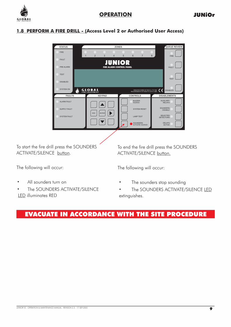
1.8 PERFORM A FIRE DRILL - (Access Level 2 or Authorised User Access)
To end the fire drill press the
The following will occur:
The sounders stop sounding
The
extinguishes
button.
LED
SOUNDERS
ACTIVATE/SILENCE
SOUNDERS ACTIVATE/SILENCE
.
�
�
EVACUATE IN ACCORDANCE WITH THE SITE PROCEDURE
G LO B A LF I R E E Q U I P M E N T
JUNiOr
9JUNIOR V3 - OPERATION & MAINTENANCE MANUAL - REVISION 2.3 - 17-SEP-2005
To start the fire drill press the SOUNDERS
ACTIVATE/SILENCE .
The following will occur:
All sounders turn on
The SOUNDERS ACTIVATE/SILENCE
illuminates RED
button
LED
�
�

Entry and Exit of Caretaker Test Mode
Press the QUEUE REVIEW - TEST first, then the CONTROLS - LAMP TEST momentarily.
(The FAULTS - PROC FAULT
button button
LED will light momentarily, this is OK).
Test mode can be activated at anytime except when:
· There is a FIRE· SOUND ALARMS have been activated· Something is already in TEST MODE (Test Sounders or Test Zones)· You are in Programming Mode· You are Installation Mode
When Caretaker Test Mode is entered 'INITIALISING' may be displayed for up to 20 secondsdepending on the system size.
Caretaker Test Mode is exited by pressing .
· The TEST LED will be lit· The buzzer will sound for 0.5 seconds every 5 seconds (same as FAULT indication).
· The message “ DETECTOR TEST MODE “ will be displayed on the LCD· The Zones in test mode will be displayed on the LCD - “ ALL ZONES “
SYSTEM RESET
Indication of Caretaker Test Mode
ALARM SILENCE will not stop this.·
STATUS QUEUE REVIEWZONES
FAULTS KEYPAD CONTROLS DISABLEMENTS
FIRE
FAULT
PRE-ALARM
TEST
DISABLED
SYSTEM ON
ALARM FAULT
SUPPLY FAULT
SYSTEM FAULT
ENTERESC
DELAYS
ACTIVE
SELECTED
DETECTORS
SOUNDERS
DISABLE
AUXILIARY
RELAYS
SOUNDERS
ACTIVATE/ SILENCE
SYSTEM RESET
LAMP TEST
BUZZER
SILENCE
DISABLED
TEST
FAULT
FIRE1 2 3 4 5 6 7 8
MANUFACTURED IN THE E.U. TO THE
REQUIREMENTS OF EN54 Pt 2 & Pt 4 1999
OPERATION
1.9 CARETAKER TEST MODE - Authorised User Access(One-Man Walk-Through Test)
G LO B A LF I R E E Q U I P M E N T
JUNiOr
10JUNIOR V3 - OPERATION & MAINTENANCE MANUAL - REVISION 2.3 - 17-SEP-2005

OPERATION
Logging
Devices Under Test
Indication When a Device is Tested
Individual detector tests are not logged (they would fill the log very quickly)Entry to Caretaker Test Mode is logged
All detectors and callpoints in all Zones will be put into test modeDetectors and callpoints not assigned to Zones will also be put into test mode
When a detector is activated (using smoke spray for example):
The LED on the detector is activated whilst the detector is above the fire alarm thresholdThe Main Panel Conventional and Loop Sounders will operate for 1 second, if selected to doso. (See Function 7.3)
The event is reported on the Main Panel and Repeater LCD displays for 15 seconds
Testing More Than One Device
Disablements
Sensor sensitivity
Other
Detectors and callpoints can only be tested one at a time. The LED must be extinguished onthe current device before moving on to test the next device. (Don't use too much smoke spray.)
All disablements for sounders, loop and detectors are ignored during Caretaker Test Mode.However the LED on disabled detectors will not be lit when the detector is tested (all other aspects ofthe test will be as normal).
This will not be changed on entry to test mode (so at night the sensitivity may be high andduring the day low - depending on the system settings).
Whilst in Caretaker Test Mode the SOUND ALARMS button will remain functionalCaretaker Test Mode can be initiated from a Main Panel or Repeater
1.9 CARETAKER TEST MODE (continued...)
G LO B A LF I R E E Q U I P M E N T
JUNiOr
11JUNIOR V3 - OPERATION & MAINTENANCE MANUAL - REVISION 2.3 - 17-SEP-2005

STATUS QUEUE REVIEWZONES
FAULTS KEYPAD CONTROLS DISABLEMENTS
FIRE
FAULT
PRE-ALARM
TEST
DISABLED
SYSTEM ON
ALARM FAULT
SUPPLY FAULT
SYSTEM FAULT
ENTERESC
DELAYS
ACTIVE
SELECTED
DETECTORS
SOUNDERS
DISABLE
AUXILIARY
RELAYS
SOUNDERS
ACTIVATE/ SILENCE
SYSTEM RESET
LAMP TEST
BUZZER
SILENCE
DISABLED
TEST
FAULT
FIRE1 2 3 4 5 6 7 8
MANUFACTURED IN THE E.U. TO THE
REQUIREMENTS OF EN54 Pt 2 & Pt 4 1999
OPERATION
1.10 DISABLEMENTS - (Authorised User Access)
1.10.1 SELECTED DETECTORS
SELECTED
DETECTORS
When activated:
The SELECTED DETECTORS will be illuminated
The STATUS - DISABLED will be illuminated
The QUEUE REVIEW - DISABLED will be illuminated
The disabled detectors can be reviewed using theDISABLED QUEUE REVIEW
The SELECTED DETECTORS button will only operate ifthere is at least one detector set to SELECTIVEDISABLEMENT.
Re-pressing the SELECTED DETECTORS button againwill re-enable the detectors.
LED
LED
LED
button
Using the programming functions (see the ‘Installation & Commissioning Manual’) individual detectors can be set forSELECTIVE DISABLEMENT. When the SELECTED DETECTORS button is activated those detectors will be disabled. (This may berequired, for example, in a building with smoke detectors inside a room reserved for cigarette smokers. During the day it wouldbe wise to disable these detectors in order to prevent the obvious false alarms it would otherwise generate.)
G LO B A LF I R E E Q U I P M E N T
JUNiOr
12JUNIOR V3 - OPERATION & MAINTENANCE MANUAL - REVISION 2.3 - 17-SEP-2005

STATUS QUEUE REVIEWZONES
FAULTS KEYPAD CONTROLS DISABLEMENTS
FIRE
FAULT
PRE-ALARM
TEST
DISABLED
SYSTEM ON
ALARM FAULT
SUPPLY FAULT
SYSTEM FAULT
ENTERESC
DELAYS
ACTIVE
SELECTED
DETECTORS
SOUNDERS
DISABLE
AUXILIARY
RELAYS
SOUNDERS
ACTIVATE/ SILENCE
SYSTEM RESET
LAMP TEST
BUZZER
SILENCE
DISABLED
TEST
FAULT
FIRE1 2 3 4 5 6 7 8
MANUFACTURED IN THE E.U. TO THE
REQUIREMENTS OF EN54 Pt 2 & Pt 4 1999
OPERATION
1.10 DISABLEMENTS (continued...)
1.10.2 SOUNDERS DISABLE
G LO B A LF I R E E Q U I P M E N T
JUNiOr
13JUNIOR V3 - OPERATION & MAINTENANCE MANUAL - REVISION 2.3 - 17-SEP-2005
STATUS QUEUE REVIEWZONES
FAULTS KEYPAD CONTROLS DISABLEMENTS
FIRE
FAULT
PRE-ALARM
TEST
DISABLED
SYSTEM ON
ALARM FAULT
SUPPLY FAULT
SYSTEM FAULT
ENTERESC
DELAYS
ACTIVE
SELECTED
DETECTORS
SOUNDERS
DISABLE
AUXILIARY
RELAYS
SOUNDERS
ACTIVATE/ SILENCE
SYSTEM RESET
LAMP TEST
BUZZER
SILENCE
DISABLED
TEST
FAULT
FIRE1 2 3 4 5 6 7 8
MANUFACTURED IN THE E.U. TO THE
REQUIREMENTS OF EN54 Pt 2 & Pt 4 1999
To disable the relay and I/O module outputs press theAUXILIARY RELAYS .
The AUXILIARY RELAYS illuminates AMBER.
The STATUS - DISABLED illuminates AMBER.
Re-press the AUXILIARY RELAYS button to re-enable therelays and I/O modules.
button
LED
LED
The QUEUE REVIEW-DISABLED illuminates AMBER.LED
AUXILIARY
RELAYS
1.10.3 AUXILIARY RELAYS
The AUXILIARY RELAYS DISABLEMENT button enables and disables all relay and I/O module outputs. Thismeans that those outputs will remain unchanged if a fire or fault occurs. The outputs that are controlled bythis button include the normally energised FAULT relay, the FAULT I/O group, the EVAC relay as well as theI/O modules fitted to the analogue loops and, of course, the auxiliary relays.
By pressing this button, all sounders on the system will be disabled. Its associated LED will light up.
The DISABLED LED will also be lit.
By pressing SOUNDERS DISABLE button once more, the LED will turn off and all sounders will re-enable

STATUS QUEUE REVIEWZONES
FAULTS KEYPAD CONTROLS DISABLEMENTS
FIRE
FAULT
PRE-ALARM
TEST
DISABLED
SYSTEM ON
ALARM FAULT
SUPPLY FAULT
SYSTEM FAULT
ENTERESC
DELAYS
ACTIVE
SELECTED
DETECTORS
SOUNDERS
DISABLE
AUXILIARY
RELAYS
SOUNDERS
ACTIVATE/ SILENCE
SYSTEM RESET
LAMP TEST
BUZZER
SILENCE
DISABLED
TEST
FAULT
FIRE1 2 3 4 5 6 7 8
MANUFACTURED IN THE E.U. TO THE
REQUIREMENTS OF EN54 Pt 2 & Pt 4 1999
If any detector detects a pre-alarm condition, the STATUS- PRE-ALARM will light up AMBER.LED
FOLLOW SITE SPECIFIC INSTRUCTIONS
1.12 IF THE PANEL DISPLAYS A PRE-ALARM
If the system detects a fault, the STATUS - FAULTwill light up AMBER.
LED
CALL THE MAINTENANCE ENGINEER
OPERATION
1.11 IF THE PANEL DISPLAYS A FAULT
G LO B A LF I R E E Q U I P M E N T
JUNiOr
14JUNIOR V3 - OPERATION & MAINTENANCE MANUAL - REVISION 2.3 - 17-SEP-2005
1.10.4 ENABLE / DISABLE ZONES
In order to Enable/Disable a zone follow the procedure described below:
1 - Enter either a valid User or Programming Code.
2 - Select Function 3.1 (Zones Disable/Assign), using the arrow keys. Press ENTER when menu 3 is
reached.
3 - Using the arrow keys once more, select function 3.1 and press .
4 - Select the zone to be disabled using the arrow keys and press .
5 - The present status of the zone is shown. To change it, press and change the status using the
arrow keys from enabled to disabled and vice versa. When selection is complete press OK/Enter.
To exit press the ESC key. Each consecutive press of the ESC key will revert back one step.
If any zones are disabled during this time, the DISABLED LED in the STATUS area of the panel's fascia will
be lit. The DISABLED LED in the QUEUE REVIEW area will also be lit. If the latter LED flashes, this gives the
indication that more than one disblement has taken place in the system. To scroll through these multiple
disablements, press the DISABLED button in the QUEUE REVIEW area.
��
��
��
��
ENTER
ENTER
ENTER

SIM CARD CONNECTOR
MAINTENANCE
2.1 SIM CARD REPLACEMENT
This procedure is required when a software upgrade is supplied on a SIM CARD. The original SIM CARDalso holds all the system configuration (settings) so this data must first be uploaded to a PC in order that itcan be downloaded into the new SIM CARD once it has been fitted.
In some cases the replacement SIM CARD will have been pre-programmed with the site configuration. Inthis case it is not necessary to upload the configuration from the original SIM CARD.
The procedure assumes that the power has been removed from the panel.
WARNING
ENSURE THAT THE POWER IS TURNED OFF
The SIM CARD is mounted on the back ofthe main board.
Release the by pulling in the
direction of the arrows ( ).
With the retaining clips held in the releasedposition, push the SIM CARD forward anddown until it is almost horizontal with themain panel board.
Lift the SIM CARD off the connector.
To install the replacement SIM CARD,locate it on the connector almosthorizontally with the main panel board,push it up and back gently until theretaining clips snap into position.
Download the panel configuration fromthe PC if SIM is not pre-programmed.
retaining clips
Uploading and downloading requires an RS232lead and PC software.
See installation Manual Section 8-4-2 forUpload/Download instructions.
ELECTRO-STATIC SENSITIVE DEVICES (ESD)
TAKE SUITABLE ESD PRECAUTIONS WHEN
REMOVING OR INSTALLING PRINTED
CIRCUIT BOARDS.
G LO B A LF I R E E Q U I P M E N T
JUNiOr
JUNIOR MAIN BOARD
SECTION 2 - MAINTENANCE
15JUNIOR V3 - OPERATION & MAINTENANCE MANUAL - REVISION 2.3 - 17-SEP-2005
JUNiOr SIM CARD

MAINTENANCE
2.2 REPLACING THE ELECTRICAL MAINS FUSE
G LO B A LF I R E E Q U I P M E N T
JUNiOr
2.3 BATTERY VOLTAGE AND CHARGER CHECKS
On the panel battery connector, measure the battery voltage. This should be 27.5V +/- 0.2V. Switch offthe primary supply and check that the battery voltage does not drop significantly. Carry out a test on adetector or manual callpoint with the primary supply disconnected to ensure that the batteries are healthy.
NOTE: BATTERIES MUST BE REPLACED PERIODICALLY IN ACCORDANCE WITH THEMANUFACTURER'S RECOMMENDATION. ALWAYS USE SEALED LEAD ACID BATTERIES.
2.4 USE OF PROGRAMMING FUNCTIONS FOR MAINTENANCE
The following programming functions can be used to check that the panel is operating correctly.
Note that to use these functions the installer needs to have granted ‘User Access’ to the followingfunctions. By default, access is denied.
1 Review Historic Log
All the functions associated with reviewing events and settings.
The panel logs all events in an internal event log. It can store a rolling 2000 entries. When it is full the latest entry isadded and the oldest entry discarded.
Help is automatically displayed on entry to the function because it is not possible to display a log entry and help atthe same time.Use to scroll through events in the log.
1-1 Display Historic Log
��
16JUNIOR V3 - OPERATION & MAINTENANCE MANUAL - REVISION 2.3 - 17-SEP-2005
NEUTRALLIVE
MEANWELL
DANGER220 VOLTS
MODEL: PS-45-27
EARTH

1-3 Clear Historic Log
1-5 Read/Clear Autostart Count
7-1 Device Count, Type & Value
7-2 Test Sounders
7-3 Sounders on Test Activation
7-4 Test Zones
7-6 Light LED on device
Clears the Historic Log.
Every time the Panel's power is cycled, the Autostart count is incremented. SYSTEM RESETs from the front panelbutton do not increment the Autostart count.
Use this function to check that all loop devices are present.
Use to select the device address on that loop.
This function is also useful to confirm the address of the various different types of devices connected to the AnalogueLoop.
Note that in Installation Mode all information is live i.e. the count of devices will change as the panel learns anddevice types will be updated if they change. In Active Mode only the device value is live.
Use this function to test the audibility of the sounders in a more comfortable manner than pressing SOUNDALARMS.
The Panel Conventional Sounders will sound for 1 second then be silenced for 9 seconds.
This function allows you to choose an audible confirmation that a device has detected a fire when in test mode. Theaudible confirmation consists of a 1 second period of sounder operation. The settings selected by this function areused by ‘7-4 Test Zones’ and ‘6-4-1 Activate ASET Mode (SAM)’.
ALL SOUNDERS ON DETECTOR TEST activates the Panel Conventional and Loop Sounders.
using this function AFTER ‘7-4 Test Zones’ and ‘6-4-1 Activate ASET Mode (SAM)’ will NOT change thesettings for the zones already in test mode and the loops already in ASET mode.
Select the Zones you wish to put into test mode.
Exit programming mode, but DO NOT press SYSTEM RESET as this clears all test modes.
In test mode when a detector is activated the LED on the detector will be illuminated and the event will bereported on the Panel (and Repeaters) for 15 seconds. If selected then the sounders will also operate for 1second. The LED on the detector is not latched and will clear when the alarm level falls below the alarmthreshold for the device.
Pressing TEST QUEUE REVIEW will report the zones that are in Test Mode.
This function can be used to confirm the physical location of a specific detector.
Select the device and SWITCHED ON and press ENTER. The device will typically take a few seconds torespond.
7 Monitor Device Counts & Test
Note -
Reset must be pressed to switch off LEDs.Note -
MAINTENANCEG LO B A LF I R E E Q U I P M E N T
JUNiOr
17JUNIOR V3 - OPERATION & MAINTENANCE MANUAL - REVISION 2.3 - 17-SEP-2005

MAINTENANCE
2.5 GETTING INTO PROGRAMMING MODE
G LO B A LF I R E E Q U I P M E N T
JUNiOr
KEYPAD
18JUNIOR V3 - OPERATION & MAINTENANCE MANUAL - REVISION 2.3 - 17-SEP-2005
ENTERESC
When the Panel is powered up it will be necessary to enter the panel programming mode. Familiarizeyourself with this section before proceeding to the next section in the manual and powering up thepanel.
Programming mode is accessed via the front panel keypad as pictured below.
To program device and zone text messages, it is essential to use the Loader PC based software.
Logging In
To enter programming mode you need to log in.
The Panel must be powered up and must have initialized itself i.e. NOT be showing the‘INITIALIZING’ message.
Press ENTER on the Keypad. You must now input your Installer access code. See page 6 AccessLevels. You have unlimited attempts but if code entry is not started within 10 seconds then the panelwill revert back to it’s default screen. While entering the code you are allowed up to 5 secondsbetween key presses.
The programming functions are arranged using a menu system.
To select a function or sub-menu use either and ENTER.ESC takes you up a menu level.
The top level menus are:
1 Review Historic Log3 Zones - Disable & Assign4 Sounders - Disable & Assign5 Input/Output - Disable & Assign6 Device Set-up7 Monitor Device Counts & Test8 General
Most functions operate in a consistent manner using the standard keys. The item that is beingchanged is usually highlighted with a flashing cursor.
Function Selection
��

MAINTENANCE
2.6 LOGBOOK
In accordance with EN54 part 14, it is the user's responsibility to maintain a logbook and to record allevents resulting from or affecting the system. The logbook should be kept in a place accessible toauthorised persons (preferably near the control panel).
One or more identifiable individuals should be appointed to oversee or carry out all entries in the logbook.The names of these persons (and any changes of responsible person) should be recorded.
All events should be properly recorded (events include real and false fire alarms, faults, pre-alarmwarnings, tests, temporary disconnections and service visits). A brief note of any work carried out oroutstanding should be made.
Sample pages of the logbook are provided here and can be photocopied to produce a logbook thatconforms to EN54-14. The sample below is for the reference data (e.g. the name of the responsibleperson), whilst the sample on the next page is for entry of event data.
REFERENCE DATA
Name and address:
Responsible person: Date:_________________________
________________________ Date:_________________________
________________________ Date:_________________________
________________________ Date:_________________________
The system was installed by:_______________________________________________
and is maintained under contract by:________________________________________
_______________________________until:___________________________________
Telephone number:____________________________________
should be contacted if service is required.
G LO B A LF I R E E Q U I P M E N T
JUNiOr
19JUNIOR V3 - OPERATION & MAINTENANCE MANUAL - REVISION 2.3 - 17-SEP-2005

MAINTENANCE
2.7 EVENT DATA SHEET
DATE TIME EVENT INITIALSACTION REQUIREDDATE
COMPLETED
G LO B A LF I R E E Q U I P M E N T
JUNiOr
20JUNIOR V3 - OPERATION & MAINTENANCE MANUAL - REVISION 2.3 - 17-SEP-2005