juniper networks g1 cmts · juniper networks g1 cmts ... cable modem termination system (cmts). the...
TRANSCRIPT

Juniper Networks, Inc.
1194 North Mathilda Avenue
Sunnyvale, CA 94089
USA
408-745-2000
www.juniper.net
Part Number: 530-008284-01, Revision 1
Juniper NetworksG1 CMTS
Installation and Operation

••••••••••••••••••••••••••••••••••••••••••••••••••••••••••
ii
Copyright © 2002, Juniper Networks, Inc. All rights reserved. Juniper Networks is registered in the U.S. Patent and Trademark Office and in other countries as a trademark of Juniper Networks, Inc. Broadband Cable Processor, ERX, ESP, G1, G10, G-series, Internet Processor, JUNOS, JUNOScript, M5, M10, M20, M40, M40e, M160, M-series, NMC-RX, SDX, ServiceGuard, T320, T640, T-series, UMC, and Unison are trademarks of Juniper Networks, Inc. All other trademarks, service marks, registered trademarks, or registered service marks are the property of their respective owners. All specifications are subject to change without notice.
Products made or sold by Juniper Networks (including the M5, M10, M20, M40, M40e, M160, and T320 routers, T640 routing node, and the JUNOS software) or components thereof might be covered by one or more of the following patents that are owned by or licensed to Juniper Networks: U.S. Patent Nos. 5,473,599, 5,905,725, 5,909,440, 6,333,650, 6,359,479, and 6,406,312.
G1 CMTS Installation and OperationCopyright © 2002, Juniper Networks, Inc.All rights reserved. Printed in USA.
Writer: Jerry IsaacIllustrations: Paul GilmanCovers and template design: Edmonds Design
Revision History10 October 2002—First edition.
Juniper Networks assumes no responsibility for any inaccuracies in this document. Juniper Networks reserves the right to change, modify, transfer, or otherwise revise this publication without notice.
The Chassis Control Module and its corresponding G1 CMTS software perform encryption that is subject to U.S. Customs and Export regulations and shall not be exported, sold or transferred to a country outside the USA and Canada without an appropriate export license from the U.S. Government. The specific Regulations governing exports of encryption products are set forth in the Export Administration Regulations, 15 C.F.R. (Code of Federal Regulations), Parts 730-774.

••••••••••••••••••••••••••••••••••••••••••••••••
Table of Contents iii
Table of ContentsAbout This Manual
Purpose ...............................................................................................................xiiiOrganization ........................................................................................................xiiiDocument Conventions ....................................................................................... xiv
Notes, Cautions, and Warnings......................................................................xvG1 CMTS Document Set........................................................................................xv
Part 1Installation and Configuration
Chapter 1G1 CMTS Introduction ...........................................................................................3
Overview ................................................................................................................3G1 CMTS Features and Functions ...........................................................................4
Functional Overview........................................................................................4Broadband Cable Processor ASIC.....................................................................5
G1 CMTS Components ............................................................................................5G1 CMTS Management ...........................................................................................6G1 CMTS Hardware Overview.................................................................................6
Chapter 2Preparation for Installation............................................................................. 11
Safety Precautions ................................................................................................11Notices..................................................................................................................13Power ...................................................................................................................14AC Power..............................................................................................................14DC Power .............................................................................................................14Environment.........................................................................................................15Mounting ..............................................................................................................15Tools and Equipment Required for Installation .....................................................16Characterization of Installation Site.......................................................................17Summary Checklist ...............................................................................................22

••••••••••••••••••••••••••••••••••••••••••••••••••••••••••
G1 CMTS Installation and Operationiv
Noise Measurement Methodology.........................................................................23Average Upstream Noise Measurement .........................................................23Peak Upstream Noise Measurement ..............................................................24
Additional Characterization Tables .......................................................................26Verification of Shipping Cartons ...........................................................................27G1 CMTS Installation Checklist .............................................................................27
Chapter 3Installation .................................................................................................................29
Rack Mounting .....................................................................................................29Ground the Chassis ...............................................................................................31Cable the G1 CMTS ...............................................................................................32
Cable the F-connector Ports...........................................................................32Cable the Ethernet RJ-45 Ports ......................................................................34
Attach a PC to the G1 CMTS..................................................................................34Connect to Power Source......................................................................................35
AC Power ......................................................................................................35DC Power ......................................................................................................35
Chapter 4Configuration and Operation ..........................................................................37
Power On the G1 CMTS ........................................................................................37Power On and Configure the PC ...........................................................................39
Log In and Out of the G1 CMTS .....................................................................40Initial Configuration of the G1 CMTS.....................................................................40
Slot Numbers.................................................................................................41Interfaces ......................................................................................................41Port ...............................................................................................................42Channel .........................................................................................................42Create Usernames and Passwords.................................................................43Configure Miscellaneous Parameters .............................................................43View and Save Running Configuration...........................................................43Configure a Downstream Channel .................................................................44Configure an Upstream Channel....................................................................45Configure the Fast Ethernet Network Interface..............................................46Configure a Management Interface................................................................47
Management Tasks...............................................................................................48Get Help ........................................................................................................48Define Usernames, Passwords, and Privileges...............................................48Set the Clock and Date ..................................................................................49Set the Hostname..........................................................................................49Configure Banners.........................................................................................50

••••••••••••••••••••••••••••••••••••••••••••••••••••••••••
Table of Contents v
RF Tasks ...............................................................................................................50Add an Upstream Channel.............................................................................50Move an Upstream Channel...........................................................................50Configure an Upstream Modulation Profile ....................................................51Enable Upstream Multicast and Broadcast .....................................................55Create a Virtual Private Network....................................................................55Edit a CM Configuration File ..........................................................................56
Convert to ASCII File ..............................................................................60Edit the ASCII File...................................................................................63Create the Binary File .............................................................................63Display the Binary File............................................................................63
NSI Tasks ..............................................................................................................64DHCP Server Parameters...............................................................................64
Subscriber Groups ..................................................................................65DHCP Server Configurations...................................................................65DHCP-Bootrequest Broadcasting.............................................................66DHCP Provisioning Scenarios .................................................................66
Shared Secret ................................................................................................69SNMP Server Parameters...............................................................................69Domain Name Server Address.......................................................................70File and Directory Management.....................................................................70Configuration Management ...........................................................................71Ping and Traceroute ......................................................................................71
Part 2Troubleshooting and Maintenance
Chapter 5RF Measurements ..................................................................................................75
Downstream RF Measurement in CATV Mode ......................................................75Downstream RF Measurement in Spectrum Analyzer Mode .................................77Upstream RF Measurement ..................................................................................79
Chapter 6Troubleshooting ......................................................................................................83
Features for Troubleshooting ................................................................................83Flap-List .........................................................................................................83
Use the Flap-List for Troubleshooting .....................................................87Local Event Log .............................................................................................89Debug Commands.........................................................................................90Various CLI Commands .................................................................................91
show cable modem ................................................................................92show tech-support ..................................................................................94
ServiceGuard Management System................................................................94

••••••••••••••••••••••••••••••••••••••••••••••••••••••••••
G1 CMTS Installation and Operationvi
CMTS Power and Bootup Issues............................................................................95CMTS Is Not Powering Up .............................................................................95CMTS Does Not Successfully Boot Up ............................................................95CMTS Does Not Boot Up With the Upgraded Software Release......................95CMTS Powers Down......................................................................................96
Configuration Issues—Ideal HFC Plant..................................................................96CM Cannot Successfully Range......................................................................96CM Cannot Establish IP Connectivity.............................................................97CM Cannot Successfully Register ...................................................................97CM Throughput is Slow..................................................................................98
HFC Plant-Related Issues ....................................................................................102CM Cannot Successfully Range....................................................................102CM Throughput is Slow................................................................................103
Chapter 7Upgrades.................................................................................................................... 105
Download the Image ..........................................................................................106FTP Session From CMTS to Host .................................................................106FTP Session From Host to CMTS .................................................................106
Apply, Test, and Commit the Upgrade................................................................107
Part 3Appendixes
Appendix AAgency Certifications ........................................................................................ 111
Safety...................................................................................................111EMC .....................................................................................................111Immunity .............................................................................................112
Appendix BHeadend Architecture ....................................................................................... 113
Appendix CSecurity ...................................................................................................................... 115
Groups................................................................................................................115Privileges ............................................................................................................116Commands .........................................................................................................116Users ..................................................................................................................116

••••••••••••••••••••••••••••••••••••••••••••••••••••••••••
Table of Contents vii
Appendix DG1 CMTS Local Log Events ............................................................................ 117
Appendix ERadio Frequency (RF) Specifications .....................................................121
Appendix FCoaxial Cable Requirements ........................................................................125
Appendix GEIA Channel Plans................................................................................................127
Part 4Index
IndexIndex.............................................................................................................................135

••••••••••••••••••••••••••••••••••••••••••••••••••••••••••
G1 CMTS Installation and Operationviii

••••••••••••••••••••••••••••••••••••••••••••••••
List of Figures ix
List of FiguresList of Figures
Figure 1: Typical CMTS Location..........................................................................4Figure 2: G1 CMTS Data Flow ..............................................................................5Figure 3: G1 CMTS – Front View..........................................................................6Figure 4: G1 CMTS – Rear View, AC Power..........................................................7Figure 5: G1 CMTS – Rear View, DC Power .........................................................7Figure 6: Top View of Chassis ..............................................................................8Figure 7: Average Upstream Noise Measurement Example................................24Figure 8: Peak Upstream Noise Measurement Example.....................................25Figure 9: Rack-Mounted Chassis ........................................................................31Figure 10: Example of Allocation of Multiple Channels Per Port ..........................32Figure 11: G1 CMTS Connectors ..........................................................................33Figure 12: Cable Connections ..............................................................................34Figure 13: DC Power Terminal Block ...................................................................36Figure 14: G1 CMTS LEDs....................................................................................38Figure 15: Downstream RF Signal (CATV Mode) ..................................................76Figure 16: Downstream RF Signal (Spectrum Analyzer Mode) .............................78Figure 17: Single Upstream Burst ........................................................................80Figure 18: Multiple Upstream Bursts....................................................................81Figure 19: Headend Architecture .......................................................................114

List of Figures
••••••••••••••••••••••••••••••••••••••••••••••••••••••••••
G1 CMTS Installation and Operationx

••••••••••••••••••••••••••••••••••••••••••••••••
List of Tables xi
List of TablesList of Tables
Table 1: Document Conventions .....................................................................xivTable 2: Power Source Input Requirements......................................................14Table 3: G1 CMTS Environmental Specifications ..............................................15Table 4: RF Plant/HFC Environment Characterization ......................................17Table 5: Existing DOCSIS Service Characterization...........................................18Table 6: Upstream CMTS Parameter Characterization ......................................19Table 7: Downstream CMTS Parameter Characterization .................................20Table 8: Upstream Frequency Spectrum Utilization..........................................21Table 9: Pre-Installation Requirement Summary Checklist ...............................22Table 10: Average Noise Spectrum Analyzer Settings .........................................23Table 11: Peak Noise Spectrum Analyzer Setup..................................................24Table 12: Existing DOCSIS Service Characterization...........................................26Table 13: G1 CMTS Installation Checklist............................................................27Table 14: Power Supply LED ..............................................................................38Table 15: G1 CMTS Front LEDs ..........................................................................39Table 16: Module Slot Assignment .....................................................................41Table 17: Cable Interface to Ethernet Port Association .......................................41Table 18: Downstream Channel Assignment ......................................................41Table 19: Upstream Channel Assignment...........................................................42Table 20: Fast Ethernet Interface to Ethernet Port Association ...........................42Table 21: Downstream Channel Parameter Ranges............................................44Table 22: Upstream Channel Parameter Ranges.................................................45Table 23: Interval Usage Codes ..........................................................................51Table 24: Upstream Modulation Profile Parameters ...........................................52Table 25: Modulation Profiles 1, 2, and 3 ...........................................................53Table 26: Modulation Profile Interval Parameters...............................................54Table 27: CM Configuration File TLV Type Names..............................................56Table 28: Flap-list Sort Parameter ......................................................................84Table 29: Flap-list Statistics ................................................................................86Table 30: Flap-list Thresholds .............................................................................87Table 31: Flap-list Association to Potential Issues ...............................................87Table 32: Local Event Log Headings Displayed...................................................90Table 33: Event-defining Debug Command Parameters .....................................91Table 34: Parameters Displayed by ‘show cable modem’ Command .................92Table 35: Description of Online States ...............................................................92Table 36: Description of CM Operational States .................................................93Table 37: Group/Privilege Matrix......................................................................115Table 38: G1 CMTS Local Log Events................................................................118Table 39: Downstream RF Channel Transmission Characteristics ....................121Table 40: Upstream RF Channel Transmission Characteristics .........................122

List of Tables
••••••••••••••••••••••••••••••••••••••••••••••••••••••••••
G1 CMTS Installation and Operationxii
Table 41: Downstream RF Signal Output Characteristics ..................................122Table 42: DOCSIS Downstream Channel Rates and Spacing ............................123Table 43: DOCSIS Maximum Upstream Channel Rates and Widths..................123Table 44: Coaxial Cable Requirements .............................................................125Table 45: EIA Channel Plan ..............................................................................127

••••••••••••••••••••••••••••••••••••••••••••••••
About This Manual xiii
About This Manual
This section describes important information about the design of this document.
Purpose
The purpose of this document, G1 CMTS Installation and Operation, is to provide the procedures required to properly install, configure, operate, troubleshoot, and upgrade the G1 Cable Modem Termination System (CMTS).
The intended audience for this information is the technicians and engineers who will operate and maintain the G1 CMTS.
Organization
G1 CMTS Installation and Operation is organized as follows:
! Chapter 1, “G1 CMTS Introduction” – Provides a G1 CMTS functional and hardware overview.
! Chapter 2, “Preparation for Installation” – Provides the procedures that must be followed in preparation for the installation of the G1 CMTS in the headend.
! Chapter 3, “Installation” – Describes the complete installation procedure for the G1 CMTS.
! Chapter 4, “Configuration and Operation” – Describes the initial configuration procedure for the G1 CMTS, and additional procedures used to perform various operational tasks.
! Chapter 5, “RF Measurements” – Provides the procedures for measuring the downstream and upstream RF signals of the G1 CMTS using a spectrum analyzer.
! Chapter 6, “Troubleshooting” – Identifies common issues associated with the operation and configuration of the G1 CMTS, the HFC plant, and CM provisioning, along with recommendations for troubleshooting and resolving these issues.
! Chapter 7, “Upgrades” – Provides the procedures required to upgrade the software of the G1 CMTS.
! Appendix A, “Agency Certifications” – Listing of government agency certifications and approvals.

Document Conventions
••••••••••••••••••••••••••••••••••••••••••••••••••••••••••
G1 CMTS Installation and Operationxiv
! Appendix B, “Headend Architecture” – Provides an illustration of a typical cable headend architecture.
! Appendix C, “Security” – Describes the groups and privileges used to implement security and user access in the command line interface (CLI).
! Appendix D, “G1 CMTS Local Log Events” – Lists the Juniper Networks-specific local log events for the G1 CMTS.
! Appendix E, “Radio Frequency (RF) Specifications” – Provides DOCSIS RF specifications for reference purposes.
! Appendix F, “Coaxial Cable Requirements” – Provides coaxial requirements for usage with the HFC Connector Modules.
! Appendix G, “EIA Channel Plans” – Provides the EIA (Electronic Industries Association) frequency plans.
Document Conventions
The following document conventions are used in this manual:
Table 1: Document Conventions
General Conventions Italic font Denotes a) emphasis, b) first use of a new term, or c) a document title.
Screen Name font Denotes a) the on-screen name of a window, dialog box or field, or b) keys on a keyboard.
Software Conventions Computer font Font denotes code or messages displayed on-screen.
Computer Bold font Font denotes literal commands and parameters that you enter exactly as shown.
<Computer Italic> font Font denotes parameter values that require a user-defined input.
The value strings are enclosed in angle brackets <...>.
[parameter] Square brackets denote optional parameters.
{parameter} Braces denote required parameters.
| Vertical bars separate parameters in a group from which you must choose only one.

••••••••••••••••••••••••••••••••••••••••••••••••••••••••••
About This Manual xv
G1 CMTS Document Set
Notes, Cautions, and Warnings
G1 CMTS Document Set
! G1 CMTS Installation and Operation
! G1 CMTS Functional Description
! G-series CMTS CLI Reference
! G-series CMTS SNMP and Enterprise MIB Specification
A note indicates information that might be helpful in a particular situation, or information that might otherwise be overlooked.
A caution indicates a situation that requires careful attention. Failure to observe a cautionary note could result in injury or discomfort to yourself, or serious damage to the product.
A warning is intended to alert the user of the presence of uninsulated dangerous voltage within the product’s enclosure that may present a risk of electric shock.

G1 CMTS Document Set
••••••••••••••••••••••••••••••••••••••••••••••••••••••••••
G1 CMTS Installation and Operationxvi

••••••••••••••••••••••••••••••••••••••••••••••••
1
Part 1Installation and Configuration
! G1 CMTS Introduction on page 3
! Preparation for Installation on page 11
! Installation on page 29
! Configuration and Operation on page 37

••••••••••••••••••••••••••••••••••••••••••••••••••••••••••
G1 CMTS Installation and Operation2

••••••••••••••••••••••••••••••••••••••••••••••••
G1 CMTS Introduction 3
Chapter 1G1 CMTS Introduction
Overview
This chapter provides an introduction to the G1 Cable Modem Termination System.
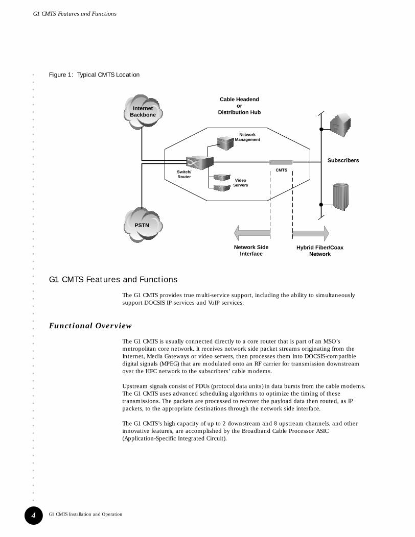
The G1 CMTS manages Internet data and voice. It functions as the interface between the service networks—Internet, public switched telephone network (PSTN)—and the hybrid fiber/coax (HFC) network of subscribers, as shown in Figure 1 on page 4. This is the “last mile” of broadband service, with the CMTS typically located in the cable headend or distribution hub. It is targeted at the following data and voice aggregation applications:
! Large CATV Hub Sites — DOCSIS multi-service, residential and commercial IP network access over HFC networks maintained by cable television (CATV) multiple service operators (MSOs) needing enhanced integrated data, voice and video in large metropolitan areas.
! Small CATV Hub Sites — smaller hub sites aggregated over metropolitan fiber rings supporting Gigabit Ethernet.
G1 CMTS Features and Functions
••••••••••••••••••••••••••••••••••••••••••••••••••••••••••
G1 CMTS Installation and Operation4
Figure 1: Typical CMTS Location
G1 CMTS Features and Functions
The G1 CMTS provides true multi-service support, including the ability to simultaneously support DOCSIS IP services and VoIP services.
Functional Overview
The G1 CMTS is usually connected directly to a core router that is part of an MSO’s metropolitan core network. It receives network side packet streams originating from the Internet, Media Gateways or video servers, then processes them into DOCSIS-compatible digital signals (MPEG) that are modulated onto an RF carrier for transmission downstream over the HFC network to the subscribers’ cable modems.
Upstream signals consist of PDUs (protocol data units) in data bursts from the cable modems. The G1 CMTS uses advanced scheduling algorithms to optimize the timing of these transmissions. The packets are processed to recover the payload data then routed, as IP packets, to the appropriate destinations through the network side interface.
The G1 CMTS’s high capacity of up to 2 downstream and 8 upstream channels, and other innovative features, are accomplished by the Broadband Cable Processor ASIC (Application-Specific Integrated Circuit).
Cable Headendor
Distribution HubInternet
Backbone
PSTN
VideoServers
NetworkManagement
Switch/Router
CMTS
Subscribers
Network SideInterface
Hybrid Fiber/CoaxNetwork

••••••••••••••••••••••••••••••••••••••••••••••••••••••••••
G1 CMTS Introduction
G1 CMTS Components
5
Broadband Cable Processor ASIC
The Broadband Cable Processor ASIC provides all-digital processing of the return path. This, plus advanced noise cancellation and equalization algorithms, enables modulation rates beyond QPSK and allows traditionally problematic frequency ranges of the upstream spectrum to be utilized. All-digital processing also accommodates full spectrum analysis by capturing statistics of the upstream band in real time.
The Broadband Cable Processor ASIC incorporates key DOCSIS MAC (Media Access Control) functions such as concatenation, fragmentation, encryption and decryption. Accelerating these functions in hardware provides a high-performance, scalable CMTS solution that can process thousands of simultaneous DOCSIS service flows.
Advanced timing and digital signal processing algorithms allow more efficient use of the RF spectrum resulting in increased channel capacity.
G1 CMTS Components
The two modules of the G1 CMTS are described below. See Figure 2 for a graphical depiction of the data flow through the modules in a chassis.
! DOCSIS Module – Performs all data processing functions. Processes IP data into DOCSIS packets. Converts and modulates data for RF transmission. Reverses these processes for upstream data. Supports the Fast Ethernet port for the network side data, and supports the F-connectors for the HFC cabling.
! Chassis Control Module – Provides management interface. Controls redundant protection functions and supplies software image to the DOCSIS Module. Runs the SNMP agent and environmental monitoring.
Figure 2: G1 CMTS Data Flow
ManagementData
ManagementPort
Chassis Control Module
DOCSIS Module
DOCSIS Data
DOCSIS Data
IP DataHybrid
Fiber/Coax
NetworkSide
Interface
G1 CMTS
G1 CMTS Management
••••••••••••••••••••••••••••••••••••••••••••••••••••••••••
G1 CMTS Installation and Operation6
G1 CMTS Management
The G1 CMTS supports the following system management applications and tools:
! CLI – The Command Line Interface provides the most comprehensive controls and is instrumental for installation, configuration, and upgrade tasks.
! NMS – The G1 CMTS can interact with SNMPv2c and SNMPv3-based Network Management Systems using DOCSIS 1.0 and DOCSIS 1.1 MIBs, and G1 CMTS enterprise MIBs. Events can conditionally be reported as SYSLOG messages or SNMP traps.
! ServiceGuard Management System – This optional advanced diagnostics application with a Java GUI provides a rendition of a spectrum analyzer for acquiring data on upstream transmission cable performance. It incorporates an integrated Impairment Identification tool that allows for unattended monitoring of statistics to characterize compromised performance to a potential cause (such as impulse or burst noise, narrow band ingress, or microreflections).
G1 CMTS Hardware Overview
This section provides an overview of the modules and various hardware components of the G1 CMTS, and where they reside within the chassis. This overview presents material that is specific to the installation and configuration of the G1 CMTS. For more details and specifications regarding these assemblies, see the G1 CMTS Functional Description.
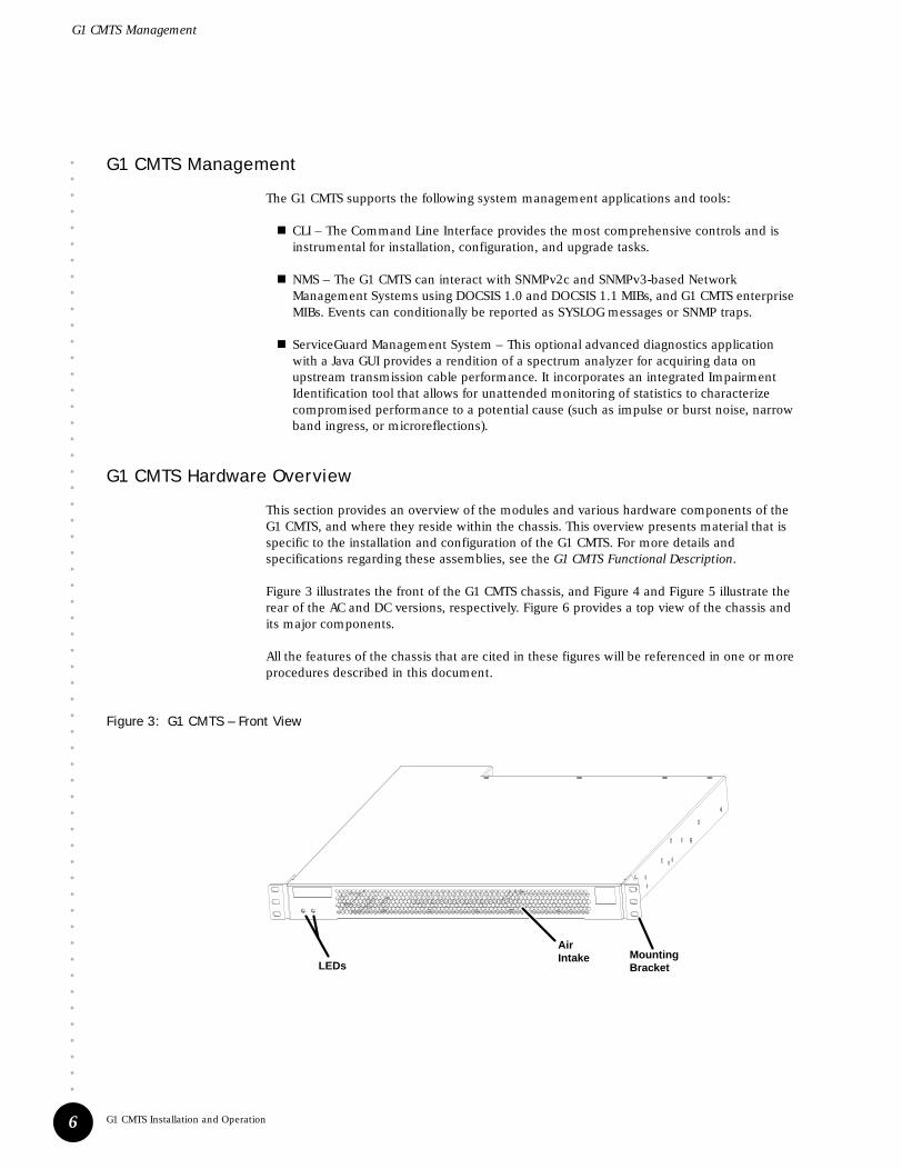
Figure 3 illustrates the front of the G1 CMTS chassis, and Figure 4 and Figure 5 illustrate the rear of the AC and DC versions, respectively. Figure 6 provides a top view of the chassis and its major components.
All the features of the chassis that are cited in these figures will be referenced in one or more procedures described in this document.
Figure 3: G1 CMTS – Front View
AirIntake
LEDsMountingBracket

••••••••••••••••••••••••••••••••••••••••••••••••••••••••••
G1 CMTS Introduction
G1 CMTS Hardware Overview
7
Figure 4: G1 CMTS – Rear View, AC Power
Figure 5: G1 CMTS – Rear View, DC Power
Fan
ChassisGround Nuts
AC PowerReceptacle
PowerSupply LED
DC TerminalGuard

G1 CMTS Hardware Overview
••••••••••••••••••••••••••••••••••••••••••••••••••••••••••
G1 CMTS Installation and Operation8
Figure 6: Top View of Chassis
DOCSIS Module
Chassis Control Module
Fan Fan FanFan
PowerSupply
Front of Chassis
20.6
in (
524
mm
)17.1 in (434 mm)
22.5
in (
572
mm
)
12.3 in (313 mm)

••••••••••••••••••••••••••••••••••••••••••••••••••••••••••
G1 CMTS Introduction
G1 CMTS Hardware Overview
9
Following is a brief explanation of each feature referenced in Figure 3 through Figure 6:
! DOCSIS Module—Module that contains the Broadband Cable Processor ASIC and resides between the Network Side Interface (NSI) and the Hybrid Fiber/Coax (HFC) interface.
! Chassis Control Module—Module that performs management and monitoring functions.
! Chassis Ground Nuts—Location where the earth ground connection to the chassis is made.
! Air Intake—Slotted openings along the front of the chassis where air is drawn into the chassis for cooling the installed modules and power supply.
! LEDs—LEDs in the front of the chassis that provide an indication of the operational status of the system.
! Mounting Brackets—Removable brackets that attach to the sides of the chassis and are used to secure the system to the rack.
! Power Supply—Converts AC or DC power supplied to the CMTS into the DC voltages required by the modules.
! Power Supply LED—Indicates the status of the power supply.
! Fans—Provide the airflow for cooling the system components.
! AC Power Receptacle—AC power cord receptacle on the AC power supply.
! DC Terminal Guard—Plastic guard that covers the DC power terminal block on the DC power supply.

G1 CMTS Hardware Overview
••••••••••••••••••••••••••••••••••••••••••••••••••••••••••
G1 CMTS Installation and Operation10

••••••••••••••••••••••••••••••••••••••••••••••••
Preparation for Installation 11
Chapter 2Preparation for Installation
This chapter provides the installation site requirements and the procedures that must be followed in preparation for the installation of the G1 CMTS in the headend.
The installation procedures described in this manual assume that the procedures and the checklist provided in this chapter have been successfully completed and approved by the user and Juniper Networks field engineers.
All the steps required to successfully install the G1 CMTS are summarized at the end of this chapter in Table 13 on page 27.
Safety Precautions
! Only trained and certified personnel should be involved in the installation of the CMTS.
! Prior to lifting and moving the G1 CMTS, ensure that the path you will be taking is totally unobstructed.
! To avoid back injury when lifting the G1 CMTS, avoid bending your back to achieve lift leverage. Instead, keep your back in the upright position, and bend at the knees. Also avoid twisting your back while lifting.
! Always rack mount a system from the bottom up to maintain the lowest possible center of gravity of the entire rack with its equipment.
! Never attempt to move the G1 CMTS while any cables or power cords are still connected.
! Ensure that any loose articles of clothing are well clear of the fans prior to powering up the G1 CMTS.
During the preparation and installation of the G1 CMTS, it is very important to adhere to the precautions presented in this section to avoid physical injury due to lifting, moving, or rack mounting the CMTS.
During the preparation and installation of the G1 CMTS, it is very important to adhere to the precautions presented in this section to avoid physical injury due to an electrical hazard.

Safety Precautions
••••••••••••••••••••••••••••••••••••••••••••••••••••••••••
G1 CMTS Installation and Operation12
! We recommend that at least two installers be present when connecting the G1 CMTS to its power source.
! Remove all jewelry that can act as a conductor of electricity such as watches, rings, bracelets, and necklaces.
! Prior to making any power connections, locate the emergency power-off switch and ensure that the path between where the G1 CMTS will be installed and the power-off switch is unobstructed.
! Prior to making any power connections, survey the immediate area to ensure that no additional electrical safety hazards exist (such as ungrounded equipment or power cords, or damp, moist areas that could conduct electricity).
! Use the factory-supplied AC power cord. This cord is grounded and appropriately rated for the G1 CMTS.
! Use the factory-supplied DC power cord ring lugs, and wire according to your local code for the DC power cord connection to the G1 CMTS.
! Attach all power cords to their appropriate terminals (AC or DC) in the rear of the G1 CMTS prior to plugging any power cord into its respective power source (AC or DC).
! Never apply excessive force when attaching a power cord to a terminal or power source if it does not readily mate with ease. Having to apply an unusual amount of force can indicate that electrical leads are bent and damaged, or that an improper connection is being attempted.
! Ensure that the G1 CMTS chassis is properly grounded to earth prior to connecting any source of power. See “Ground the Chassis” on page 31 for more details.
During the preparation and installation of the G1 CMTS, it is very important to adhere to the precautions presented in this section to avoid damaging the G1 CMTS.

••••••••••••••••••••••••••••••••••••••••••••••••••••••••••
Preparation for Installation
Notices
13
Notices
! This equipment is intended only for installation in a restricted access location within a building.
! This equipment is intended for indoor use only.
! This equipment does not have a direct copper connection to the outside plant.
Risk of explosion if battery is replaced by an incorrect type. Dispose of used batteries according to the instructions.
This is a Class A product. In a domestic environment this product may cause radio interference in which case the user may be required to take adequate measures.
This device complies with Part 15 of the FCC Rules. Operation is subject to the following two conditions: (1) This device may not cause harmful interference, and (2) this device must accept any interference received, including interference that may cause undesired operation.

Power
••••••••••••••••••••••••••••••••••••••••••••••••••••••••••
G1 CMTS Installation and Operation14
Power
A G1 CMTS requires a maximum of 360 watts from an external power source. Its typical power consumption is approximately 205 watts. Table 2 provides the input requirements for the power source.
Table 2: Power Source Input Requirements
AC Power
The G1 CMTS requires an AC power source that operates within a voltage and frequency range of 100 to 240 VAC and 47 to 63 Hz. In addition, appropriately sized circuit protection measures must be implemented to ensure compliance with electrical regulatory standards.
Use the factory-supplied power cord for AC power.
DC Power
The G1 CMTS requires a DC power source that operates within a voltage range of –38 to –72 VDC. Within the United States, a 15-A circuit breaker (9.5 A maximum, plus margin) must be used in conjunction with the DC power source connected to the CMTS. Similarly, outside of the United States, the DC power source must have circuit breaker protection to account for a maximum current of 9.5 A, plus additional margin required by your local code.
Use the factory-supplied DC power cord ring lugs, and wire according to your local code for the DC power cord connection to the G1 CMTS.
Ensure that the CMTS chassis is properly grounded to earth prior to connecting any source of power.
Power Supply Type Voltage Current Requirements Power
AC 100 to 240 VAC
47 to 63 Hz
1.3 A Nom (230V, 70% efficiency) 290 W (Typ)
1.8 A Max (200V, 70% efficiency) 360 W (Max)
2.5 A Nom (115V, 70% efficiency) 290 W (Typ)
3.6 A Max (100V, 70% efficiency) 360 W (Max)
DC –38 to –72 VDC 6.0 A Nom (–48 VDC, 70% efficiency) 290 W (Typ)
9.5 A Max (–38 VDC, 70% efficiency) 360 W (Max)
AC power sources must use circuit breakers, rather than fuses, for current surge protection.

••••••••••••••••••••••••••••••••••••••••••••••••••••••••••
Preparation for Installation
Environment
15
Environment
The installation site must meet the specifications provided in Table 3 to maintain the proper environmental conditions for the G1 CMTS.
Table 3: G1 CMTS Environmental Specifications
Mounting
The G1 CMTS is designed for mounting in a 19-inch EIA RS-310-C equipment rack or a 23-inch AT&T DATAPHONE equipment rack. Installation into non-standard racks can still be accomplished through the additional rail mounting bracket holes provided with the CMTS.
A cable organizer is recommended to assist with the routing of cables to and from the equipment rack. The cable organizer should be mounted after the CMTS is installed.
For thermal management, airflow enters into the front of the CMTS chassis and exits through the rear. In addition, proper clearance to the front and rear of the mounting rack is recommended so that the CMTS can be easily accessed during maintenance. The recommended clearance to the front and rear of the chassis is 3 feet and 2 feet, respectively. Additional equipment can be mounted flush on either the top or bottom of the CMTS without impacting system ventilation.
Parameter Condition Requirement
Temperature Ambient Operating 0° to +40°C (0° to +104°F)
Ambient Non-operating –35° to +60°C (–31° to +140°F)
Humidity Ambient Operating and Non-operating 10% to 90% (non-condensing)
Altitude Operating and Non-operating 0 to 3048 m (10,000 ft)
Vibration Operating 5 Hz to 200 Hz, at 1.0g (1.0 oct/min)
Non-operating 5 Hz to 200 Hz, at 1.0g (1.0 oct/min)
200 Hz to 500 Hz, at 2.0g (1.0 oct/min)
Systems should be rack mounted from the bottom up to maintain the lowest possible center of gravity of the entire rack with its equipment.
Neighboring equipment must be positioned such that its ventilation exhaust does not feed into the CMTS air intake.

Tools and Equipment Required for Installation
••••••••••••••••••••••••••••••••••••••••••••••••••••••••••
G1 CMTS Installation and Operation16
Tools and Equipment Required for Installation
The following tools are needed to complete the G1 CMTS installation:
! M3 Phillips torque screwdriver
! #10 Phillips torque screwdriver
! #12 Phillips torque screwdriver
In addition, the following supplies might be required:
! RF cables and adapters
! Ethernet cables with RJ-45 connectors
The following equipment is required to configure the G1 CMTS and verify that the RF system has been setup properly:
! PC with asynchronous terminal emulation
! RF spectrum analyzer
! RF power meter

••••••••••••••••••••••••••••••••••••••••••••••••••••••••••
Preparation for Installation
Characterization of Installation Site
17
Characterization of Installation Site
Several parameters of the installation site need to be characterized prior to the installation of the CMTS. These parameters relate to specific aspects of the installation site system, HFC network connections, and CMTS downstream and upstream transmissions. The information collected will allow field engineers to verify that the installation site environment is compatible with the G1 CMTS. Table 4 is provided to collect information regarding the RF plant and HFC environment.
Table 4: RF Plant/HFC Environment Characterization
Table 5 is provided to collect information regarding the existing DOCSIS services supported by the installation site. If there are no existing DOCSIS services supported, skip Table 5 and proceed to subsequent tables. If more than two DOCSIS services exist, additional characterization tables can be found in “Additional Characterization Tables” on page 26.
Parameter Value
Plant architecture type ____ HFC ____ All Coax
Number of optical links within HFC
Distance between optical links within HFC ____ max ____ average
Amplifier cascade depth from node ____ max ____ average
Homes passed per node ____ max ____ average
Total homes passed by installation site
Node combining ratio per port ___:1 upstream ___:1 downstream
Average upstream noise measurement (see note below) ____ dB
Peak upstream noise measurement (see note below) ____ dB
Passive loss from upstream receiver to CMTS ____ dB
Maximum tap value used ____ dB
Maximum tap output level at highest frequency ____ dBmV
Maximum drop loss allowed from tap to home ____ dB
Method used for return path alignment
DOCSIS services offered? If yes, complete Table 5 on page 18. ____ yes ____ no
Upstream frequency spectrum utilization (complete Table 8 on page 21)
Note: A statistical sample of the total nodes terminated at the headend (~10%) should be taken for average and peak noise measurements per the methodology described in “Noise Measurement Methodology” on page 23.

Characterization of Installation Site
••••••••••••••••••••••••••••••••••••••••••••••••••••••••••
G1 CMTS Installation and Operation18
Table 5: Existing DOCSIS Service Characterization
Table 6 on page 19 and Table 7 on page 20 are provided to collect upstream and downstream characterization information, respectively, for the G1 CMTS to be installed. Table 8 on page 21 is used to record the utilization of the upstream frequency spectrum.
Parameter Value
1st DOCSIS Service
Upstream RF bandwidth allocated ____ MHz (max) ____ MHz (min)
Upstream modulation type ____ QPSK ____ 16QAM
Upstream input level expected at CMTS ____ dBmV
FEC enabled? If yes, FEC level parameters (T and K)
____ yes ____ no____T ____ K
Upstream measured C/N ____ dB
Downstream RF bandwidth allocated ____ MHz (max) ____ MHz (min)
Downstream modulation type ____ 64QAM ____256QAM
Downstream output signal level (relative to analog video) ____ dB
Downstream measured C/N ____ dB (DOSCIS carrier)
____ dB (Analog video carrier)
Downstream interleave depth setting ___ (# of taps) ____(increments)
2nd DOCSIS Service
Upstream RF bandwidth allocated ____ MHz (max) ____ MHz (min)
Upstream modulation type ____ QPSK ____ 16QAM
Upstream input level expected at CMTS ____ dBmV
FEC enabled? If yes, FEC level parameters (T and K)
____ yes ____ no____ T ____ K
Upstream measured C/N ____ dB
Downstream RF bandwidth allocated ____ MHz (max) ____ MHz (min)
Downstream modulation type ____ 64QAM ____256QAM
Downstream output signal level (relative to analog video) ____ dB
Downstream measured C/N ____ dB (DOSCIS carrier)
____ dB (Analog video carrier)
Downstream interleave depth setting ___ (# of taps) ____(increments)

••••••••••••••••••••••••••••••••••••••••••••••••••••••••••
Preparation for Installation
Characterization of Installation Site
19
Table 6: Upstream CMTS Parameter Characterization
Upstream Parameters Port 0 Port 1 Port 2 Port 3
Node combining ratio per port
____ : 1 ____ : 1 ____ : 1 ____ : 1
Expected channels per port
Expected port input level ____ dBmV ____ dBmV ____ dBmV ____ dBmV
Modulation type(where applicable)
_ QPSK _ 16QAM (CH0)
_ QPSK _ 16QAM (CH1)
_ QPSK _ 16QAM (CH2)
_ QPSK _ 16QAM (CH3)
_ QPSK _ 16QAM (CH4)
_ QPSK _ 16QAM (CH5)
_ QPSK _ 16QAM (CH6)
_ QPSK _ 16QAM (CH7)
_ QPSK _ 16QAM (CH0)
_ QPSK _ 16QAM (CH1)
_ QPSK _ 16QAM (CH2)
_ QPSK _ 16QAM (CH3)
_ QPSK _ 16QAM (CH4)
_ QPSK _ 16QAM (CH5)
_ QPSK _ 16QAM (CH6)
_ QPSK _ 16QAM (CH7)
_ QPSK _ 16QAM (CH0)
_ QPSK _ 16QAM (CH1)
_ QPSK _ 16QAM (CH2)
_ QPSK _ 16QAM (CH3)
_ QPSK _ 16QAM (CH4)
_ QPSK _ 16QAM (CH5)
_ QPSK _ 16QAM (CH6)
_ QPSK _ 16QAM (CH7)
_ QPSK _ 16QAM (CH0)
_ QPSK _ 16QAM (CH1)
_ QPSK _ 16QAM (CH2)
_ QPSK _ 16QAM (CH3)
_ QPSK _ 16QAM (CH4)
_ QPSK _ 16QAM (CH5)
_ QPSK _ 16QAM (CH6)
_ QPSK _ 16QAM (CH7)
Channel width(where applicable)
Circle the applicable unit.
____ kHz/MHz (CH 0)
____ kHz/MHz (CH 1)
____ kHz/MHz (CH 2)
____ kHz/MHz (CH 3)
____ kHz/MHz (CH 4)
____ kHz/MHz (CH 5)
____ kHz/MHz (CH 6)
____ kHz/MHz (CH 7)
____ kHz/MHz (CH 0)
____ kHz/MHz (CH 1)
____ kHz/MHz (CH 2)
____ kHz/MHz (CH 3)
____ kHz/MHz (CH 4)
____ kHz/MHz (CH 5)
____ kHz/MHz (CH 6)
____ kHz/MHz (CH 7)
____ kHz/MHz (CH 0)
____ kHz/MHz (CH 1)
____ kHz/MHz (CH 2)
____ kHz/MHz (CH 3)
____ kHz/MHz (CH 4)
____ kHz/MHz (CH 5)
____ kHz/MHz (CH 6)
____ kHz/MHz (CH 7)
____ kHz/MHz (CH 0)
____ kHz/MHz (CH 1)
____ kHz/MHz (CH 2)
____ kHz/MHz (CH 3)
____ kHz/MHz (CH 4)
____ kHz/MHz (CH 5)
____ kHz/MHz (CH 6)
____ kHz/MHz (CH 7)
FEC enabled? If yes, FEC level parameters
_____ yes _____ no
____ T ____ K (CH 0)
____ T ____ K (CH 1)
____ T ____ K (CH 2)
____ T ____ K (CH 3)
____ T ____ K (CH 4)
____ T ____ K (CH 5)
____ T ____ K (CH 6)
____ T ____ K (CH 7)
_____ yes _____ no
____ T ____ K (CH 0)
____ T ____ K (CH 1)
____ T ____ K (CH 2)
____ T ____ K (CH 3)
____ T ____ K (CH 4)
____ T ____ K (CH 5)
____ T ____ K (CH 6)
____ T ____ K (CH 7)
_____ yes _____ no
____ T ____ K (CH 0)
____ T ____ K (CH 1)
____ T ____ K (CH 2)
____ T ____ K (CH 3)
____ T ____ K (CH 4)
____ T ____ K (CH 5)
____ T ____ K (CH 6)
____ T ____ K (CH 7)
_____ yes _____ no
____ T ____ K (CH 0)
____ T ____ K (CH 1)
____ T ____ K (CH 2)
____ T ____ K (CH 3)
____ T ____ K (CH 4)
____ T ____ K (CH 5)
____ T ____ K (CH 6)
____ T ____ K (CH 7)
Channel frequency
(where applicable)
____ MHz (CH 0)____ MHz (CH 1)____ MHz (CH 2)____ MHz (CH 3)____ MHz (CH 4)____ MHz (CH 5)____ MHz (CH 6)____ MHz (CH 7)
____ MHz (CH 0)____ MHz (CH 1)____ MHz (CH 2)____ MHz (CH 3)____ MHz (CH 4)____ MHz (CH 5)____ MHz (CH 6)____ MHz (CH 7)
____ MHz (CH 0)____ MHz (CH 1)____ MHz (CH 2)____ MHz (CH 3)____ MHz (CH 4)____ MHz (CH 5)____ MHz (CH 6)____ MHz (CH 7)
____ MHz (CH 0)____ MHz (CH 1)____ MHz (CH 2)____ MHz (CH 3)____ MHz (CH 4)____ MHz (CH 5)____ MHz (CH 6)____ MHz (CH 7)
Required channel input level
(where applicable)
____ dBmV (CH 0)____ dBmV (CH 1)____ dBmV (CH 2)____ dBmV (CH 3)____ dBmV (CH 4)____ dBmV (CH 5)____ dBmV (CH 6)____ dBmV (CH 7)
____ dBmV (CH 0)____ dBmV (CH 1)____ dBmV (CH 2)____ dBmV (CH 3)____ dBmV (CH 4)____ dBmV (CH 5)____ dBmV (CH 6)____ dBmV (CH 7)
____ dBmV (CH 0)____ dBmV (CH 1)____ dBmV (CH 2)____ dBmV (CH 3)____ dBmV (CH 4)____ dBmV (CH 5)____ dBmV (CH 6)____ dBmV (CH 7)
____ dBmV (CH 0)____ dBmV (CH 1)____ dBmV (CH 2)____ dBmV (CH 3)____ dBmV (CH 4)____ dBmV (CH 5)____ dBmV (CH 6)____ dBmV (CH 7)

Characterization of Installation Site
••••••••••••••••••••••••••••••••••••••••••••••••••••••••••
G1 CMTS Installation and Operation20
Table 7: Downstream CMTS Parameter Characterization
Downstream Parameters Port 0 Port 1
DOCSIS Module #___
Node combining ratio per port ____ : 1 ____ : 1
Channel frequency allocated ____ MHz ____ MHz
Modulation type _ 64QAM _256QAM _ 64QAM _256QAM
Output signal level (relative to analog video)
____ dB ____ dB
Required channel output level ____ dBmV ____ dBmV
Interleave depth setting ___ [I] (# of taps)___ [J] (increments)
___ [I] (# of taps)___ [J] (increments)

••••••••••••••••••••••••••••••••••••••••••••••••••••••••••
Preparation for Installation
Characterization of Installation Site
21
Table 8: Upstream Frequency Spectrum Utilization
Frequency Description of Utilization Frequency Description of Utilization
5 – 6 MHz 24 – 25 MHz
6 – 7 MHz 25 – 26 MHz
7 – 8 MHz 26 – 27 MHz
8 – 9 MHz 27 – 28 MHz
9 – 10 MHz 28 – 29 MHz
10 – 11 MHz 29 – 30 MHz
11 – 12 MHz 30 – 31 MHz
12 – 13 MHz 31 – 32 MHz
13 – 14 MHz 32 – 33 MHz
14 – 15 MHz 33 – 34 MHz
15 – 16 MHz 34 – 35 MHz
16 – 17 MHz 35 – 36 MHz
17 – 18 MHz 36 – 37 MHz
18 – 19 MHz 37 – 38 MHz
19 – 20 MHz 38 – 39 MHz
20 – 21 MHz 39 – 40 MHz
21 – 22 MHz 40 – 41 MHz
22 – 23 MHz 41 – 42 MHz
23 – 24 MHz

Summary Checklist
••••••••••••••••••••••••••••••••••••••••••••••••••••••••••
G1 CMTS Installation and Operation22
Summary Checklist
Table 9 provides a summary checklist of the pre-installation requirements discussed in this document. This checklist should be completed and approved by Juniper Networks field engineers to ensure the installation site is properly prepared for installing the G1 CMTS.
Table 9: Pre-Installation Requirement Summary Checklist
Requirement Verified
Safety
Compliance verified with all local and national regulatory requirements
Equipment to be positioned in a clear, dry, dust-free area
Power
AC Power
AC-input supply operates within range of 100 to 240 VAC and 47 to 63 Hz
Appropriate circuit protection in place for compliance with area electric regulations
DC Power
DC-input supply operates within range of –38 to –72 VDC
Appropriate circuit protection in place for compliance with area electric regulations
Environment
Ambient temperature conditions satisfied
Ambient humidity conditions satisfied
Altitude conditions satisfied
Vibration conditions satisfied
Mounting
19-inch rack, 23-inch rack, or appropriate non-standard rack or shelf available
Cable organizer available for mounting rack
Adequate access clearance to front, rear, and sides of CMTS
Hardware
Specified tools and supplies available
Test equipment available for installation and verifying RF setup
Installation Site
Characterization of RF Plant/HFC environment parameters completed
Characterization of existing DOCSIS services completed
Characterization of upstream CMTS parameters completed
Characterization of downstream CMTS parameters completed

••••••••••••••••••••••••••••••••••••••••••••••••••••••••••
Preparation for Installation
Noise Measurement Methodology
23
Noise Measurement Methodology
This section describes the proper methodology for conducting average and peak upstream noise measurements. The procedures provided are designed to establish a consistent methodology for obtaining the requested information during the characterization of the installation site. The HP 8591C is the recommended spectrum analyzer to use for conducting these measurements.
Average Upstream Noise Measurement
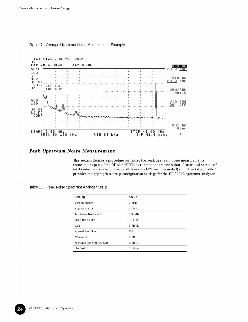
This section defines a procedure for taking the average upstream noise measurements requested as part of the RF plant/HFC environment characterization. A statistical sample of total nodes terminated at the installation site (10% recommended) should be taken. Table 10 provides the appropriate setup configuration settings for the HP 8591C spectrum analyzer.
Table 10: Average Noise Spectrum Analyzer Settings
1. Connect the spectrum analyzer to the selected upstream signal at the upstream splitter or at the CMTS upstream port.
2. Configure the spectrum analyzer per the values defined in Table 10.
3. Start the measurement.
Upon completing the measurement, the analyzer display should resemble Figure 7 on page 24.
Setting Value
Start Frequency 2 MHz
Stop Frequency 45 MHz
Resolution Bandwidth 100 kHz
Video Bandwidth 30 kHz
Scale 5 dB/div
Internal Amplifier On
Attenuator 0 dB
Reference Level Offset -28 dB
Reference Level (see note below) -5 dBmV
Number of Averages 100
Note: This value might need to be adjusted for your particular test environment.
Noise Measurement Methodology
••••••••••••••••••••••••••••••••••••••••••••••••••••••••••
G1 CMTS Installation and Operation24
Figure 7: Average Upstream Noise Measurement Example
Peak Upstream Noise Measurement
This section defines a procedure for taking the peak upstream noise measurements requested as part of the RF plant/HFC environment characterization. A statistical sample of total nodes terminated at the installation site (10% recommended) should be taken. Table 11 provides the appropriate setup configuration settings for the HP 8591C spectrum analyzer.
Table 11: Peak Noise Spectrum Analyzer Setup
Setting Value
Start Frequency 2 MHz
Stop Frequency 45 MHz
Resolution Bandwidth 100 kHz
Video Bandwidth 30 kHz
Scale 5 dB/div
Internal Amplifier Off
Attenuator 0 dB
Reference Level of Headend 0 dBmV
Max Hold 1 minute

••••••••••••••••••••••••••••••••••••••••••••••••••••••••••
Preparation for Installation
Noise Measurement Methodology
25
1. Connect the spectrum analyzer to the selected upstream signal at the upstream splitter or at the CMTS upstream port.
2. Configure the spectrum analyzer per the values defined in Table 11.
3. Start the measurement.
Upon completing the measurement, the analyzer display should resemble Figure 8 on page 25.
Figure 8: Peak Upstream Noise Measurement Example

Additional Characterization Tables
••••••••••••••••••••••••••••••••••••••••••••••••••••••••••
G1 CMTS Installation and Operation26
Additional Characterization Tables
If the installation site supports more than two DOCSIS services, the characterization of the additional services is to be captured in Table 12.
Table 12: Existing DOCSIS Service Characterization
Parameter Value
____ DOCSIS Service
Upstream RF bandwidth allocated ____ MHz (max) ____ MHz (min)
Upstream modulation type ____ QPSK ____ 16QAM
Upstream input level expected at CMTS ____ dBmV
FEC enabled? If yes, FEC level parameters (T and K)
____ yes ____ no____T ____ K
Upstream measured C/N ____ dB
Downstream RF bandwidth allocated ____ MHz (max) ____ MHz (min)
Downstream modulation type ____ 64QAM ____256QAM
Downstream output signal level (relative to analog video) ____ dB
Downstream measured C/N ____ dB (DOSCIS carrier)
____ dB (Analog video carrier)
Downstream interleave depth setting ___ (# of taps) ____(increments)
____ DOCSIS Service
Upstream RF bandwidth allocated ____ MHz (max) ____ MHz (min)
Upstream modulation type ____ QPSK ____ 16QAM
Upstream input level expected at CMTS ____ dBmV
FEC enabled? If yes, FEC level parameters (T and K)
____ yes ____ no____ T ____ K
Upstream measured C/N ____ dB
Downstream RF bandwidth allocated ____ MHz (max) ____ MHz (min)
Downstream modulation type ____ 64QAM ____256QAM
Downstream output signal level (relative to analog video) ____ dB
Downstream measured C/N ____ dB (DOSCIS carrier)
____ dB (Analog video carrier)
Downstream interleave depth setting ___ (# of taps) ____(increments)

••••••••••••••••••••••••••••••••••••••••••••••••••••••••••
Preparation for Installation
Verification of Shipping Cartons
27
Verification of Shipping Cartons
Prior to beginning the installation of the G1 CMTS, it is important to verify that the contents of the shipping cartons are identical to the contents listed on the packing lists. In addition, a careful inspection of the shipped contents should be performed to ensure that they are not damaged in any manner. If any contents are missing or damaged, please report this to Juniper Networks customer support.
Following are the steps that are recommended to verify the contents of the shipping cartons match the packing list:
1. Carefully open the shipping cartons. Pay attention to any instructions printed on each shipping carton.
2. Remove all the contents of the shipping cartons. When lifting heavy contents, be sure to follow the safety precautions listed in “Safety Precautions” on page 11.
3. Verify that the contents of the shipping cartons are identical to the contents listed on the packing lists.
4. Open all accessory kits that are included in the shipment. Verify that the contents are identical to the contents listed on the accessory kit packing lists.
G1 CMTS Installation Checklist
Table 13 summarizes all the steps outlined in this document that are required to successfully install the G1 CMTS in the headend. We recommend that copies of this table be made and used to keep track of the status of each G1 CMTS being installed.
Table 13: G1 CMTS Installation Checklist
Step Page Number Completion Status
Preparation for Installation
Complete all checklists in “Preparation for Installation” page 11
Completely review G1 CMTS Installation and Operation, including the safety precautions —
Verify the contents of the shipping cartons page 27
Verify the contents of all accessory kits
Rack Mounting and Grounding the Chassis
Ensure proper ventilation clearance surrounding the G1 CMTS
page 29If applicable, install the rack mounting brackets
Install an equipment shelf in the rack
Mount the chassis to the rack
Crimp the supplied two-ring lug connector to the earth ground strap
page 31Attach the earth ground strap to the chassis
Attach the earth ground strap to earth ground

G1 CMTS Installation Checklist
••••••••••••••••••••••••••••••••••••••••••••••••••••••••••
G1 CMTS Installation and Operation28
Cable the G1 CMTS
Determine how the cable plant nodes will be connected to the downstream and upstream ports of the G1 CMTS
page 32Connect each of the two downstream ports to its respective node
Connect each of the four upstream ports to its respective node
Dress all cables appropriately
Connect the RJ-45 connector of the Ethernet cable to the 10/100BASE-T DATA port on the G1 CMTS
page 34
Connect the other end of the Ethernet data cable to its respective network equipment in the headend
Connect the RJ-45 connector of the Ethernet cable to the 10/100BASE-T MGT port on the G1 CMTS
Connect the other end of the Ethernet mangement cable to its respective network equipment in the headend
Dress all cables appropriately
Attach a PC to the G1 CMTS
Connect the serial cable to the COM port of the G1 CMTS page 34
Connect the other end of the serial cable to the serial port on the PC
Connect to Power Source
Plug the power cord into the power receptacle (AC) or terminal block (DC) page 35
Plug the other end of the power cord to its respective power source(s)
Power On the G1 CMTS
Ensure that the power sources are on page 37
Check all chassis and power supply LEDs
Power On and Configure the PC
Power on the PC, launch the asynchronous terminal emulation application, and establish a direct serial connection with the Chassis Control Module page 39Check for correct boot banner and system prompt on PC
Log into the G1 CMTS
Initial Configuration of the G1 CMTS
If desired, create new usernames and passwords page 43
Configure miscellaneous parameters page 43
View and save running configuration page 43
Configure downstream channel parameters page 44
Configure upstream channel parameters page 45
Configure the Fast Ethernet network interface page 46
Configure the management interface page 47
Step Page Number Completion Status

••••••••••••••••••••••••••••••••••••••••••••••••
Installation 29
Chapter 3Installation
This chapter describes the complete installation procedure for the G1 CMTS. It is assumed that all safety precautions and procedures described in “Preparation for Installation” on page 11 have been followed prior to performing the procedures presented in this chapter. We recommend that the entire installation process in this chapter be read prior to performing the actual G1 CMTS installation.
Rack Mounting
This section describes the process for rack mounting the G1 CMTS into an EIA standard 19-inch rack. The mounting brackets are compatible with either of the following racks:
! Standard 1-3/4” EIA wide1-1/4”, 1/2”, 1-1/4”12-24 tapped
! Standard 2” EIA wide1”, 1”12-24 tapped
The G1 CMTS is shipped from the factory with mounting brackets attached to the front of the chassis for front-rack mounting. If mid-rack mounting is desired, the mounting brackets can be removed and reinstalled 10” from the front of the chassis. The chassis can also be mounted slightly forward in the rack by installing the mounting brackets 2.5” from the front of the chassis.
The following procedure assumes that all the contents of the shipping cartons, including the G1 CMTS chassis, have been removed.
The G1 CMTS must be rack mounted on top of an equipment shelf. The mounting brackets attached to the chassis are not designed to support the weight of the G1 CMTS without an equipment shelf.
In general, when more than one piece of equipment is mounted into a rack, the heaviest piece of equipment should be installed at the bottom of the rack, and each successive piece installed should be lighter than the piece immediately below it. For planning purposes, a G1 CMTS weighs approximately 20 lb (9.1 kg).

Rack Mounting
••••••••••••••••••••••••••••••••••••••••••••••••••••••••••
G1 CMTS Installation and Operation30
1. Prior to rack mounting, ensure that proper clearance is maintained between the G1 CMTS chassis and its surroundings to allow adequate air ventilation to flow into the air intake and out of the rear of the chassis:
! A minimum of 3 feet (0.91 m) between the front of the chassis and any other object
! A minimum of 2 feet (0.61 m) between the rear of the chassis and any other object
If there is no other equipment installed in the rack, the G1 CMTS should be installed as low as possible into the rack.
2. Install an equipment shelf into the rack. For reference, the chassis dimensions are provided in Figure 6 on page 8.
3. If the chassis will be front-rack mounted, jump ahead to Step 5. If the chassis will be mid-rack mounted or mounted 2.5” forward within the rack, proceed to Step 4.
4. Remove the three screws fastening each mounting bracket to the front of the chassis, align the brackets with the corresponding hole patterns 10” from the front of the chassis (for mid-mount) or 2.5” from the front of the chassis (depending on your preference), and insert the three screws into the chassis. Apply 25 in-lb of torque to each of the three screws.
5. When lifting the chassis, be sure to follow the safety precautions listed in the “Safety Precautions” on page 11. Carefully lift and slide the G1 CMTS onto the equipment shelf.
6. Continue sliding the chassis all the way into the rack until the flanges of the mounting brackets are flush with the mounting rails of the rack, and the mounting holes in the mounting brackets are aligned with the corresponding holes in the mounting rails.
7. Using the #12 screws supplied in the accessory kit (one to three for each mounting bracket, depending on its alignment with the rack), fasten the chassis to the rack by applying 27 in-lb of torque to each of the screws (see Figure 9). Do not completely tighten any screw to its torque specification until all screws are inserted.
The G1 CMTS does not require any clearance between the bottom of the chassis and the floor. Similarly, there are no clearance requirements between the top of the chassis and the bottom of another G1 CMTS stacked above it on the same rack.

••••••••••••••••••••••••••••••••••••••••••••••••••••••••••
Installation
Ground the Chassis
31
Figure 9: Rack-Mounted Chassis
Ground the Chassis
1. Crimp the two-ring lug connector supplied in the accessory kit to a ground strap.
2. Using the two supplied #10-32 screws and washers (a washer is installed between each bolt and the lug connector), attach the ground strap to the chassis using 25 in-lb of torque on each bolt. See Figure 4 on page 7 for the location of the chassis ground nuts (the figure shows the two-ring lug connector attached to the ground nuts).
3. Attach the other end of the ground strap to earth ground.
Never power on the G1 CMTS without first grounding the chassis.

Cable the G1 CMTS
••••••••••••••••••••••••••••••••••••••••••••••••••••••••••
G1 CMTS Installation and Operation32
Cable the G1 CMTS
This section describes how to connect the two downstream and four upstream F-connector ports of the G1 CMTS. This section also describes how to connect the two 10/100BASE-T Fast Ethernet ports on the G1 CMTS.
Cable the F-connector Ports
The G1 CMTS supports a total of two downstream channels, where one channel is assigned to each physical downstream port. The G1 CMTS supports a total of 8 upstream channels which can be logically allocated to any one of the four physical upstream ports. Figure 10 illustrates an example where the number of channels allocated on each port is three, two, two, and one, respectively. The assignment of a node to a port, and the allocation of upstream channels per upstream port should be considered prior to connecting the coaxial cables from the cable plant to the G1 CMTS.
Figure 10: Example of Allocation of Multiple Channels Per Port
One possible deployment scenario for the upstream is to attach one node per upstream port and to turn on one upstream channel per node. If one of the nodes reaches capacity due to high penetration or heavy usage of bandwidth-intensive services, another channel can be provisioned on that port.
The following procedure describes how to connect to the downstream ports (see Figure 11 on page 33 for port labeling):
Prior to inserting a coaxial cable into any of the G1 CMTS F-connectors, ensure that the cable meets the requirements provided in “Coaxial Cable Requirements” on page 125.
OPTICALOPTICALOPTICALRECEIVERRECEIVERRECEIVER
Pow
er
Frequency5 MHz 15 38 42MHz
Noise & Group Delay
Pow
er
Frequency5 MHz 15 38 42MHz
Pow
er
Frequency5 MHz 15 38 42MHz
Pow
er
Frequency5 MHz 15 38 42MHz
Noise & Group Delay
FIBER FIBER NODEFIBER
G1 CMTSG1 CMTSG1 CMTS
When tightening a coaxial cable onto an F-connector, use a 7/16 in. torque wrench to apply torque according to SCTE standards.

••••••••••••••••••••••••••••••••••••••••••••••••••••••••••
Installation
Cable the G1 CMTS
33
1. Select the first node(s) in the cable plant for assignment to the first of two downstream ports.
2. Connect the coaxial cable associated with the first node(s) to the F-connector on the G1 CMTS labeled DS0.
3. If applicable, select the second node(s) in the cable plant for assignment to the second of two downstream ports.
4. Connect the coaxial cable associated with the second node(s) to the F-connector on the G1 CMTS labeled DS1.
Figure 11: G1 CMTS Connectors
The following procedure describes how to connect to the upstream ports (see Figure 11 for port labeling):
1. Select the first node(s) in the cable plant for assignment to the first of four upstream ports.
2. Connect the coaxial cable associated with the first node(s) to the F-connector on the G1 CMTS labeled US0.
3. If applicable, select the second, third, and fourth nodes in the cable plant for assignment to the remaining three upstream ports.
4. If applicable, connect the coaxial cables associated with the second, third, and fourth nodes to the F-connectors on the G1 CMTS labeled US1, US2, and US3, respectively.
5. All coaxial cables should be dressed appropriately and routed to avoid obstructing the airflow through the rear fans of the G1 CMTS (see Figure 12 on page 34). The usage of cable organizers is recommended to assist with cable routing.
In the following procedure, a node can represent a single node, or multiple nodes that are combined.
When connecting nodes to the upstream ports of the G1 CMTS, do not split a coaxial cable from one node and attach it to more than one upstream port. Doing so prevents you from using the complete features of the DOCSIS Module that were designed for supporting four separate nodes or four groups of nodes that are combined.

Attach a PC to the G1 CMTS
••••••••••••••••••••••••••••••••••••••••••••••••••••••••••
G1 CMTS Installation and Operation34
Cable the Ethernet RJ-45 Ports
1. Plug the RJ-45 connector of an Ethernet cable into the RJ-45 port of the G1 CMTS labeled DATA. This is the cable that carries the network traffic.
2. Attach the other end of the network traffic Ethernet cable to its respective network equipment in the headend.
3. Plug the RJ-45 connector of an Ethernet cable into the RJ-45 port of the G1 CMTS labeled MGT. This is the cable that carries the management traffic.
4. Attach the other end of the management traffic Ethernet cable to its respective network equipment in the headend.
Figure 12: Cable Connections
Attach a PC to the G1 CMTS
Initial configuration of the G1 CMTS requires a direct connection between a personal computer (PC) and the Chassis Control Module. Using the DB-9–to–DB-9 null modem serial cable supplied in the accessory kit, connect one end of the cable to the RS-232 DB-9 port labeled COM on the G1 CMTS (see Figure 11 on page 33), and connect the other end to the serial port on your PC.
An adapter might be needed to connect the DB-9 connector of the cable to the serial port of your PC (for example, DB-9–to–DB-25).

••••••••••••••••••••••••••••••••••••••••••••••••••••••••••
Installation
Connect to Power Source
35
Connect to Power Source
AC Power
The AC power receptacle on the G1 CMTS chassis contains a standard IEC 15-A three-prong male AC power receptacle for connecting to an AC power source (see Figure 4 on page 7). Plug the female end of the 15-A power cord into the AC power receptacle.
Plug the male end of the 15-A power cord to its power source. Always use an AC power source that supports the ground prong of the power cord.
DC Power
The G1 CMTS chassis contains a terminal block for connecting to a DC power source (see Figure 13 on page 36). The terminal block supports the connection of a second DC power source for redundancy.
The following procedure describes the steps for connecting the DC terminal block to its power source:
1. Shipped with the G1 CMTS are ring lugs that are used to connect the DC power cord to the DC terminal block. These ring lugs must be crimped to the negative (–) and positive (+) wires of the DC power cord in order to properly connect to the DC terminal block.
2. Remove the plastic guard over the DC terminal block by removing the two fastening screws (Figure 13 on page 36 shows the DC terminal block without the guard installed). The guard will be reinstalled in step 8 below.
3. Remove the screw from the negative terminal on the terminal block labeled A–, insert the screw through the ring lug of the power cord that will be attached to the negative (A–) terminal of the DC power source, and tighten the screw into the negative (A–) terminal on the terminal block. Apply 3 in-lb of torque to the screw.
4. Remove the screw from the positive terminal labeled A+ on the terminal block, insert the screw through the ring lug of the power cord that will be attached to the positive (A+) terminal of the DC power source, and tighten the screw into the positive (A+) terminal on the terminal block. Apply 3 in-lb of torque to the screw.
Ensure that you have read and taken the proper safety precautions as described in “Preparation for Installation” on page 11 prior to connecting an AC or DC power source to the G1 CMTS.
The G1 CMTS AC power supply is autosensing which enables it for usage with 115 VAC or 230 VAC.

Connect to Power Source
••••••••••••••••••••••••••••••••••••••••••••••••••••••••••
G1 CMTS Installation and Operation36
5. Connect the other end of the power cord connected to the negative (A–) terminal on the terminal block to the negative (–) terminal of the DC power source in accordance with the manufacturer’s specifications.
6. Connect the other end of the power cord connected to the positive (A+) terminal on the terminal block to the positive (+) terminal of the DC power source in accordance with the manufacturer’s specifications.
7. If a second DC power source will be used for redundancy, repeat steps 3 through 6 above using the negative terminal on the terminal block labeled B–, and the positive terminal on the terminal block labeled B+.
8. Replace the plastic guard over the DC terminal block and install the two fastening screws through the guard and into the terminal block. Apply 2.5 in-lb of torque to each screw.
Figure 13: DC Power Terminal Block
A+ A- B+ B-

••••••••••••••••••••••••••••••••••••••••••••••••
Configuration and Operation 37
Chapter 4Configuration and Operation
This chapter describes the initial configuration procedure for the G1 CMTS, and additional procedures used to perform various operational tasks. It is assumed that the installation procedures described in “Installation” on page 29 have been followed prior to performing the procedures presented in this chapter. We recommend that the entire configuration process in this chapter be read prior to performing the actual G1 CMTS configuration.
Power On the G1 CMTS
The following steps define the power-on procedure and the expected state of the two LEDs on the front of the chassis that should be monitored after the G1 CMTS is powered on.
1. Ensure that the power source connected to the G1 CMTS is on.
2. Immediately after the G1 CMTS is connected to its power source, the system will begin to power up. Check that the power supply LED in the rear of the chassis is green. This indicates normal power supply operation. If the LED is not green, see Table 14 on page 38 for other LED combinations and the corresponding action to take.
Ensure that you have read and taken the proper safety precautions as described in “Preparation for Installation” on page 11 prior to powering on the G1 CMTS.
Before returning a G1 CMTS that appears to be faulty based on its LED status, contact Juniper Networks customer support for technical assistance.

••••••••••••••••••••••••••••••••••••••••••••••••••••••••••
G1 CMTS Installation and Operation38
Table 14: Power Supply LED
3. Immediately after the G1 CMTS is connected to its power source, check that the two LEDs in the front of the chassis are both yellow (see Figure 14). This indicates that the Chassis Control Module is powering up and running its self test.
Continue to monitor these LEDs until they both become green. This indicates the successful completion of the Chassis Control Module’s self test. If the front LEDs both remain yellow indefinitely, this indicates the self test was not successful and the G1 CMTS might have to be replaced. Table 15 on page 39 summarizes the meaning of these LEDs.
Figure 14: G1 CMTS LEDs
LED State Meaning Action
Green Outputs available (normal operation) None
Green, blinking Standby mode (input power detected, but no output power)
Contact Juniper Networks technical support.
Amber – Over-current– Over-temperature– Over-voltage
– Check that the chassis and power supply fans are operating.– Ensure the air intake and exhaust are not blocked.– Ensure that the external power source is operating within specification.
Not illuminated No input power – Ensure that the external power source is on.– Ensure that the power supply is properly connected to the power cord and the power source.
The LED legend to the immediate right of the LEDs represents the status of the LEDs during normal operation, after the G1 CMTS has successfully completed its initial power-up.
When both of the front LEDs initially become green, the DOCSIS Module has not yet completed its bootup.

••••••••••••••••••••••••••••••••••••••••••••••••••••••••••
Configuration and Operation
Power On and Configure the PC
39
Table 15: G1 CMTS Front LEDs
Power On and Configure the PC
1. Power on the personal computer (PC) attached to the serial port of the G1 CMTS.
2. Launch your asynchronous terminal emulation application (such as Microsoft Windows Hyperterminal), and establish a direct connection. Configure the port settings as follows:
! Bits per second: 9600
! Data bits: 8
! Parity: None
! Stop bits: 1
! Flow control: None
3. When a successful connection is made between the PC and the G1 CMTS, the terminal emulation screen on your PC will display a banner and prompt you for a login username:
Copyright (c) 2000-2002 Juniper Networks, Inc.
G1 CMTS Release sw_rev_num
Login:
where sw_rev_num represents the software revision number
Left LED Right LED Meaning
Off Off No power
Green Green Normal operation
Yellow Yellow Chassis Control Module is powering up
Yellow Yellow Minor fault – corresponds to Warning event priority (applicable only after bootup)
Red Yellow Major fault – corresponds to Error event priority
Red Red Critical fault – corresponds to Emergency, Alert, or Critical event priority

Initial Configuration of the G1 CMTS
••••••••••••••••••••••••••••••••••••••••••••••••••••••••••
G1 CMTS Installation and Operation40
Log In and Out of the G1 CMTS
1. Type root at the login prompt and press ENTER:
Login: root
2. You will then be prompted for a password. Type changeme as the password and press ENTER:
Password: changeme
You will see the following Command Line Interface (CLI) system prompt:
GX$root#
3. If desired, you can logout of the system as follows:
GX$root# logout
Initial Configuration of the G1 CMTS
This section describes how to use the CLI to perform the initial configuration of the G1 CMTS. The complete details of the CLI can be found in the G-series CMTS CLI Reference manual.
The procedures provided herein describe how to configure the following:
! Usernames and passwords
! Miscellaneous parameters
! Configuration file
! Downstream channel parameters
! Upstream channel parameters
! A single cable interface consisting of one downstream channel and one upstream channel
! The Fast Ethernet interface that carries network traffic
! The management interface
These procedures are provided for illustration purposes. The slot and interface used in these procedures is usually specified in a general manner as <slot/if>. The actual parameters specified during your initial configuration are dependent on your particular preferences, as well as your network and HFC plant characteristics.

••••••••••••••••••••••••••••••••••••••••••••••••••••••••••
Configuration and Operation
Initial Configuration of the G1 CMTS
41
Slot Numbers
The G1 CMTS chassis contains two logical slots that can configured. The Chassis Control Module is assigned to slot 1 and the DOCSIS Module is assigned to slot 2. This relationship is summarized in Table 16. The slot number is used in conjunction with the interface number to enter the interface cable or the interface fastEthernet sub-modes.
Table 16: Module Slot Assignment
Interfaces
A cable interface is a logical entity that consists of at least one upstream and one downstream port. A cable interface is the same as a MAC domain. The traffic through both cable interfaces (0 and 1) is forwarded through the Ethernet port labeled DATA on the G1 CMTS. This relationship is summarized in Table 17.
Table 17: Cable Interface to Ethernet Port Association
The G1 CMTS is shipped with a default cable interface assignment as presented in Table 18 and Table 19. Note that the downstream and upstream channel to cable interface assignments and the upstream channel to upstream port assignments specified in these tables are the factory defaults, and can be changed through the CLI or the startup-config file. The default assignments are used if the startup-config file does not assign any downstream or upstream channels to a slot/interface (MAC domain). The procedures in this chapter assume this default assignment.
Table 18: Downstream Channel Assignment
Slot Number Module
1 Chassis Control Module
2 DOCSIS Module
Cable Interface Associated Ethernet Port
0 DATA
1
Some of the CLI commands used in the following procedures set various parameters to their default values and hence their execution is not mandatory. These commands are provided for illustration purposes.
Cable Interface Downstream Channel Downstream Port
0 0 DS0
1 1 DS1

Initial Configuration of the G1 CMTS
••••••••••••••••••••••••••••••••••••••••••••••••••••••••••
G1 CMTS Installation and Operation42
Table 19: Upstream Channel Assignment
Interface is also used describe the Fast Ethernet ports, which are also configurable. Here, interface 0 corresponds to the MGT and DATA ports of the Chassis Control Module and DOCSIS Module, respectively. The slot number is used to distinguish between these two interfaces. This relationship is summarized in Table 20.
Table 20: Fast Ethernet Interface to Ethernet Port Association
Port
A port is a physical connector. There are two downstream ports and four upstream ports (F-connectors), two Fast Ethernet ports (RJ-45), and one serial port (DB-9).
Channel
A channel is a logical entity. There are two downstream channels and eight upstream channels supported by the G1 CMTS.
Downstream channels are assigned one-each to the DS ports. Channels are enumerated 0 – 1.
Upstream channels can be assigned to any US port. Channels are enumerated 0 – 7.
Cable Interface Upstream Channel Upstream Port
0
0 US0
1
4 US2
5
1
2 US1
3
6 US3
7
Slot/Interface Associated Ethernet Port Supported By:
1/0 MGT Chassis Control Module
2/0 DATA DOCSIS Module

••••••••••••••••••••••••••••••••••••••••••••••••••••••••••
Configuration and Operation
Initial Configuration of the G1 CMTS
43
Create Usernames and Passwords
1. At the initial CLI command prompt, you are in the read-write privilege mode. If desired, you can enter the configure terminal mode and change your password from the default of changeme:
GX$root# configure terminal
GX$root(config)# username root password myword
2. You might also want to create new usernames and passwords. Because you are in the privilege mode, any newly created username will have privilege mode access:
GX$root(config)# username newuser password myword
Configure Miscellaneous Parameters
If desired, the following miscellaneous parameters can be assigned:
! Set the Hostname to Hub1-G1:
GX$root(config)# hostname Hub1-G1
Hub1-GX$root(config)#
! Set the SNMP read-only and read-write SNMP password community strings to public and private, respectively:
GX$root(config)# snmp-server community public ro
GX$root(config)# snmp-server community private rw
! Set the time to 2:30pm and the date to December 22, 2001 (you must first exit to the top level):
GX$root(config)# exit
GX$root# clock set 143000 22 12 2001
View and Save Running Configuration
To view the current configuration of the G1 CMTS, issue the following command:
GX$root# show running-config
To save the current configuration of the G1 CMTS, issue the following command. Upon booting up, the system uses the startup-config file to set the configuration:
GX$root# copy running-config startup-config
conf t can be used as an abbreviation for the configure terminal command.

Initial Configuration of the G1 CMTS
••••••••••••••••••••••••••••••••••••••••••••••••••••••••••
G1 CMTS Installation and Operation44
Configure a Downstream Channel
The procedure in this section specifies various parameters for downstream channel 0. The available downstream channels on the DOCSIS Module are channels 0–1, which always correspond to downstream ports 0–1, respectively, on the G1 CMTS. Table 21 provides the valid ranges of all parameters specified in this section.
Table 21: Downstream Channel Parameter Ranges
1. Enter the interface cable sub-mode:
GX$root# configure terminal
GX$root(config)# interface cable <slot/if>
2. Specify a frequency of 453000000 Hz for downstream channel 0:
GX$root(config-if-cslot/if)# cable downstream 0 frequency 453000000
3. Specify an RF power of 55 dBmV for downstream channel 0:
GX$root(config-if-cslot/if)# cable downstream 0 rf-power 55
4. Specify 64qam modulation for downstream channel 0:
GX$root(config-if-cslot/if)# cable downstream 0 modulation 64qam
5. Specify an interleave depth of 8 for downstream channel 0:
GX$root(config-if-cslot/if)# cable downstream 0 interleave-depth 8
Care should be taken when modifying any of the parameters associated with a downstream or upstream channel. Incorrect values specified for certain parameters can render a channel inoperative.
Parameter Range
slot 2
interface 0–1
channel (=port) 0–1
frequency DOCSIS: 91000000 to 857000000EuroDOCSIS: 109000000 to 861000000
RF power 50 to 61
modulation 64qam or 256qam
interleave depth 8, 16, 32, 64, 128

••••••••••••••••••••••••••••••••••••••••••••••••••••••••••
Configuration and Operation
Initial Configuration of the G1 CMTS
45
6. At this point, if you desire to view the downstream channel 0 parameters and status, enter the following command:
GX$root(config-if-cslot/if)# cable downstream 0 show
7. Enable downstream channel 0:
GX$root(config-if-cslot/if)# no cable downstream 0 shutdown
Configure an Upstream Channel
The procedure in this section specifies various parameters for upstream channel 0. A default modulation profile for channel 0 will be used. The available upstream channels on the DOCSIS Module are channels 0–7 and are assigned to the four upstream ports (0–3) on the G1 CMTS by default as defined in Table 19 on page 42. Table 22 provides the valid ranges of all parameters specified in this section.
Table 22: Upstream Channel Parameter Ranges
1. Enter the interface cable sub-mode:
GX$root# configure terminal
GX$root(config)# interface cable <slot/if>
2. Specify a channel width of 200000 Hz for upstream channel 0:
GX$root(config-if-cslot/if)# cable upstream 0 channel-width 200000
Care should be taken when modifying any of the parameters associated with a downstream or upstream channel. Incorrect values specified for certain parameters can render a channel inoperative.
Parameter Range
slot 2
interface 0–1
channel 0–7
port 0–3
channel width 200000–3200000 Hz
frequency DOCSIS: 5000000 to 42000000EuroDOCSIS: 5000000 to 65000000
power-level -10 to +25 dBmV
data-backoff 0–16
range-backoff 0–16
modulation-profile 1–256
minislot-size 2, 4, 8, 16, 32, 64, 128

Initial Configuration of the G1 CMTS
••••••••••••••••••••••••••••••••••••••••••••••••••••••••••
G1 CMTS Installation and Operation46
3. Specify a frequency of 5000000 Hz for upstream channel 0:
GX$root(config-if-cslot/if)# cable upstream 0 frequency 5000000
4. Specify a power level of 0 dBmV for upstream channel 0:
GX$root(config-if-cslot/if)# cable upstream 0 power-level 0
5. Specify start and stop data backoff values of 2 and 6, respectively, for upstream channel 0:
GX$root(config-if-cslot/if)# cable upstream 0 data-backoff 2 6
6. Specify start and stop range backoff values of 3 and 7, respectively, for upstream channel 0:
GX$root(config-if-cslot/if)# cable upstream 0 range-backoff 3 7
7. Specify a minislot size of 8 for upstream channel 0:
GX$root(config-if-cslot/if)# cable upstream 0 minislot-size 8
8. At this point, if you desire to view the upstream channel 0 parameters and status, enter the following command:
GX$root(config-if-cslot/if)# cable upstream 0 show
9. Enable upstream channel 0:
GX$root(config-if-cslot/if)# no cable upstream 0 shutdown
Configure the Fast Ethernet Network Interface
The G1 CMTS is shipped with default values assigned to the Fast Ethernet network interface. To view these defaults, issue the show running-config command. These defaults generally meet a user’s requirements and should not have to be modified.
The procedure in this section enables the Fast Ethernet network interface on the G1 CMTS:
1. Enter the interface fastEthernet sub-mode, specifying slot 2 and interface 0 for Fast Ethernet port DATA:
GX$root# configure terminal
GX$root(config)# interface fastEthernet 2/0
2. Enable Fast Ethernet port DATA:
GX$root(config-if-f2/0)# no shutdown

••••••••••••••••••••••••••••••••••••••••••••••••••••••••••
Configuration and Operation
Initial Configuration of the G1 CMTS
47
Configure a Management Interface
A management interface is established by using the Fast Ethernet port labeled MGT on the G1 CMTS. The following procedure describes how to configure this interface:
1. Enter the configure terminal mode:
GX$root# configure terminal
2. Assign an IP address of 192.177.122.3 for the default gateway for the management interface:
GX$root(config)# ip default-gateway 192.177.122.3 management
3. Enter the interface fastEthernet sub-mode, specifying slot 1 and interface 0 for Fast Ethernet port MGT:
GX$root(config)# interface fastEthernet 1/0
4. Assign an IP address of 192.177.122.1 and a subnet mask of 255.255.255.0 for slot 1 / interface 0:
GX$root(config-if-f1/0)# ip address 192.177.122.1 255.255.255.0
5. Enable Fast Ethernet port MGT:
GX$root(config-if-f1/0)# no shutdown
The remaining sections of this chapter provide the CLI procedures used to perform various operational tasks on the G1 CMTS. Appendix C describes the groups and privileges used to implement security and user access in the CLI. For additional details regarding the CLI, see the G-series CMTS CLI Reference.
Do not configure the Chassis Control Module management port on a 169.254/16 network. These IP addresses are used by the G1 CMTS internally, and any IP address clashes can result in unpredictable behavior.
The internal Fast Ethernet interface between the Chassis Control Module and the DOCSIS Module corresponds to slot 1 / interface 1. This interface is not accessible through the CLI, but is displayed in the ifTable in the RFC-2233 MIB.

Management Tasks
••••••••••••••••••••••••••••••••••••••••••••••••••••••••••
G1 CMTS Installation and Operation48
Management Tasks
This section describes those tasks associated with initializing and managing the G1 CMTS.
Get Help
To display a list of available commands at the current command level, enter help or a question mark at the command prompt:
GX$root# help
GX$root# ?
Notice that a carriage return is not necessary when entering a question mark.
To display a list of valid command parameters, type a question mark after a command:
GX$root# clock ?
adjust - Adjust the system clock
set - Set the time and date
To display a list of available editing keystrokes, type help edit:
GX$root# help edit
Define Usernames, Passwords, and Privileges
To define new usernames and assign them passwords and privileges, you must have a privilege of ad-rw. Use the username command as follows:
GX$root# configure terminal
GX$root(config)# username newuser1 password newpw1
In the event the password for username root is lost, you can reset the password to the default of changme by performing the following procedure on the console port (not supported within a Telnet session):
1. Reboot the CMTS by issuing the reload command or by power cycling the system.
2. When you see the following messages displayed on the console, type passwordreset:
Waiting for system to start-up ...
Waiting for completion of system initialization ...
3. When prompted, log into the CMTS as user root with a password of changeme.
To assign IP and read-write group-privilege to newuser1, use the username command as follows:
GX$root(config)# username newuser1 group ip privilege rw
To remove newuser1 from the system, use the no username command as follows:
GX$root(config)# no username newuser1

••••••••••••••••••••••••••••••••••••••••••••••••••••••••••
Configuration and Operation
Management Tasks
49
Set the Clock and Date
To set the clock and date, use the clock command as follows:
GX$root# clock set 122200 22 12 2001
Sets the clock to 12:22:00 and the date to December 22, 2001. If the usage of the NTP server clock has been enabled, it must be disabled (by issuing the no clock ntp-server command) prior to manually setting or adjusting the clock with this command.
To adjust the clock, use the clock command as follows:
GX$root# clock adjust -60
Adjusts the clock 60 seconds backwards.
To configure an NTP server, use the clock ntp-server command as follows:
GX$root# configure terminal
GX$root(config)# clock ntp-server 192.168.201.1
The NTP server at IP address 192.168.201.1 is used for setting the CMTS system clock.
To define the timezone, use the clock timezone command as follows:
GX$root(config)# clock timezone PST 8
Defines PST as the timezone, and subtracts 8 hours from UTC. The specified timezone is arbitrary.
To define daylight savings time, use one of the two forms of the clock summer-time command as follows:
GX$root(config)# clock summer-time PDT date 7 apr 2 27 oct 2
The daylight savings time zone is named PDT and is set to begin on April 7 at 2 a.m. and end on October 27 at 2 a.m.
GX$root(config)# clock summer-time PDT recurring first sun apr 2 last sun oct 2
The daylight savings time zone is named PDT and is set to begin on the first Sunday of April at 2 a.m. and end on the last Sunday of October at 2 a.m. These start and end times are standard in the USA.
To display the UTC, local, and daylight savings times, as well as the IP address of the NTP server (if configured), use the clock show command as follows:
GX$root(config)# clock show
Set the Hostname
To define a hostname, you must have a privilege of ip-rw. Use the hostname command as follows:
GX$root# configure terminal
GX$root(config)# hostname CMTS5
CMTS5$root(config)#

RF Tasks
••••••••••••••••••••••••••••••••••••••••••••••••••••••••••
G1 CMTS Installation and Operation50
Configure Banners
To define an incoming banner that is displayed when a user logs into the CMTS, use the banner incoming command as follows:
GX$root# configure terminal
GX$root(config)# banner login "Incoming Banner"
The banner displayed will be Incoming Banner:
Copyright (c) 2000-2002 Juniper Networks, Inc.
G1 CMTS Release 2.1.2.5
Incoming Banner
Login:
The banner exec, banner login, and banner motd commands can be issued in a similar fashion.
RF Tasks
This section describes those tasks associated with the RF functions of the G1 CMTS, such as dynamically adding and moving upstream channels, and configuring a modulation profile.
Add an Upstream Channel
The G1 CMTS allows upstream channels to be dynamically added to a slot/interface (MAC domain). This alleviates the need to split combining groups when a CMTS port reaches its maximum capacity.
1. Enter the interface cable sub-mode:
GX$root# configure terminal
GX$root(config)# interface cable <slot/if>
2. Add channel 4:
GX$root(config-if-cslot/if)# cable upstream 4 add
3. Enable upstream channel 4:
GX$root(config-if-cslot/if)# no cable upstream 4 shutdown
Move an Upstream Channel
The G1 CMTS allows upstream channels to be dynamically moved from one slot/interface to another.
1. Enter the interface cable sub-mode, specifying slot 2 and interface 0:
GX$root# configure terminal
GX$root(config)# interface cable 2/0

••••••••••••••••••••••••••••••••••••••••••••••••••••••••••
Configuration and Operation
RF Tasks
51
2. Disable the upstream channel to be moved (channel 4):
GX$root(config-if-c2/0)# cable upstream 4 shutdown
3. Wait at least 30 seconds after disabling the channel.
4. Remove the channel from slot 2 / interface 0:
GX$root(config-if-c2/0)# no cable upstream 4 add
5. Enter the target slot/interface, specifying slot 2 and interface 1:
GX$root(config-if-c2/0)# exit
GX$root(config)# interface cable 2/1
6. Add channel 4 to slot 2 / interface 1:
GX$root(config-if-c2/1)# cable upstream 4 add
7. Enable upstream channel 4:
GX$root(config-if-c2/1)# no cable upstream 4 shutdown
Configure an Upstream Modulation Profile
DOCSIS specifies different burst types, each associated with an Interval Usage Code (IUC), for upstream transmissions, such as request, initial, station, short, and long (see Table 23). During a burst transmission, a CM must use the burst parameters assigned for that particular type of burst. These parameters are defined in an upstream modulation profile (see Table 24). Upstream modulation profiles are assigned on a per upstream channel basis.
Table 23: Interval Usage Codes
IUC Description
request An upstream interval in which requests can be made for bandwidth for upstream data transmission.
initial An interval in which new stations (cable modems) can join the network.
station An interval in which stations are expected to perform some aspect of routine network maintenance, such as ranging or power adjustment.
short An interval in which a CM transmits one or more upstream Protocol Data Units (PDUs). The interval for a short interval is less than or equal to the Maximum Burst Size defined in the short profile.
long An interval in which a CM transmits one or more upstream Protocol Data Units (PDUs). The number of mini-slots in the interval is larger than the maximum for short interval transmissions.

RF Tasks
••••••••••••••••••••••••••••••••••••••••••••••••••••••••••
G1 CMTS Installation and Operation52
Table 24: Upstream Modulation Profile Parameters
Specifying the upstream modulation profile parameters is accomplished by using the cable modulation-profile command. The order of the parameters specified in the command is given from top to bottom in the Parameter column of Table 24.
The cable upstream modulation-profile command is used to assign an upstream modulation profile to an upstream channel.
Two of the IUCs—short and long—are used for the transmission of data to the CMTS. The burst parameters associated with these two particular IUCs significantly affect the efficiency of the upstream channel on which the CMs are transmitting, particularly the following parameters—FEC T bytes, FEC K bytes, modulation, preamble length, and shortened last codeword. In an environment with relatively low noise levels, an operator might specify the smallest number of FEC T bytes (or even turn off the FEC) and the largest number of FEC K bytes in order to minimize the overhead used for error checking. Using a modulation type of 16QAM, as opposed to QPSK, would approximately double the data bandwidth. Minimizing the preamble length and enabling shortened last codeword also increases the channel efficiency by reducing the amount of bits in a packet that are not used as part of the data payload.
However, in practice, an HFC plant might have higher levels of noise attributed to Additive White Gaussian Noise, impulse noise, and narrowband ingress. Therefore, the burst parameters must be specified so that CMs can achieve a balance between maximizing the channel bandwidth, and successfully operating within a potentially noisy upstream environment.
Parameter Range Description
FEC T bytes 0–10 The number of codeword parity bytes is 2*T (0 implies no FEC—forward error correction). T is the number of bytes that can be corrected per FEC codeword.
FEC K bytes 16–253 Codeword information bytes (not used if FEC T bytes is 0).
maxburst size 0–255 The maximum number of mini-slots that can be transmitted during this burst type.
guard time 0–255 Number of symbol times which must follow the end of this burst.
modulation 16qamqpsk
Upstream modulation type.
scrambler scrambler Determines if the scrambler is used.
scrambler seed 0–7FFF The 15-bit scrambler seed value.
diff encoding diffno-diff
Determines if differential encoding is used.
preamble length 0,2,4,...1024 – QPSK0,4,8,...1024 – 16QAM
Defines the length of the preamble in bits.
shortened last codeword fixedshortened
Determines whether the last codeword is shortened or not.

••••••••••••••••••••••••••••••••••••••••••••••••••••••••••
Configuration and Operation
RF Tasks
53
The G1 CMTS is shipped from the factory with eight pre-defined modulation profiles. Three of these eight profiles—Profiles 1, 2, and 3—are recommended for your usage (see Table 25). The remaining five profiles—Profiles 4–8—are defined for laboratory purposes and are not suitable for real-world environments. To display a particular modulation profile, use the cable modulation-profile show command.
Table 25: Modulation Profiles 1, 2, and 3
Profile 1 is defined for full QPSK operation (QPSK modulation is used in all interval types). Profile 3 is defined for mixed 16QAM and QPSK operation in which 16QAM is used for short and long intervals, and QPSK is used for all other intervals. Profile 2 should be used in place of Profile 3 if it is known that the CMs on this channel do not transmit at the same power level for 16QAM and QPSK bursts.
The following procedure describes how to create a modulation profile and assign it to an upstream channel. In this example, a modulation profile ID of 15 (out of 256) is arbitrarily chosen. Table 26 provides the ten modulation profile parameters and the specific values used in the following procedure for each of the burst intervals.
The values within Table 25 are subject to change.
Profile IUCFEC T bytes
FEC K bytes
maxburstsize guardtime modulation scrambler
scramblerseed
diffencoding
preamblelength
shortenedlastcodeword
1
request 0 16 0 6 qpsk scrambler 1 diff 68 fixed
initial 3 34 0 5 qpsk scrambler 1 diff 52 fixed
station 3 34 0 5 qpsk scrambler 1 diff 52 fixed
short 5 75 8 5 qpsk scrambler 1 diff 32 shortened
long 8 220 0 5 qpsk scrambler 1 diff 32 shortened
2
request 0 16 0 5 16qam scrambler 1 diff 188 fixed
initial 3 34 0 5 16qam scrambler 1 diff 104 fixed
station 3 34 0 5 16qam scrambler 1 diff 104 fixed
short 5 75 8 5 16qam scrambler 1 diff 64 shortened
long 8 220 0 5 16qam scrambler 1 diff 64 shortened
3
request 0 16 0 6 qpsk scrambler 1 diff 68 fixed
initial 3 34 0 5 qpsk scrambler 1 diff 52 fixed
station 3 34 0 5 qpsk scrambler 1 diff 52 fixed
short 5 75 8 5 16qam scrambler 1 diff 64 shortened
long 8 220 0 5 16qam scrambler 1 diff 64 shortened
Care should be taken when modifying any of the parameters associated with a downstream or upstream channel. Incorrect values specified for certain parameters can render a channel inoperative.

RF Tasks
••••••••••••••••••••••••••••••••••••••••••••••••••••••••••
G1 CMTS Installation and Operation54
Table 26: Modulation Profile Interval Parameters
1. Enter the configure terminal mode:
GX$root# configure terminal
2. Specify the parameters for a request interval for modulation profile 15:
GX$root(config)# cable modulation-profile 15 request 0 16 0 6 qpsk scrambler
1 diff 68 fixed
3. Specify the parameters for an initial maintenance interval for modulation profile 15:
GX$root(config)# cable modulation-profile 15 initial 3 34 0 5 qpsk scrambler
1 diff 52 fixed
4. Specify the parameters for a station maintenance interval for modulation profile 15:
GX$root(config)# cable modulation-profile 15 station 3 34 0 5 qpsk scrambler
1 diff 52 fixed
5. Specify the parameters for a short data grant interval for modulation profile 15:
GX$root(config)# cable modulation-profile 15 short 3 40 8 5 qpsk scrambler 1
diff 36 shortened
6. Specify the parameters for a long data grant interval for modulation profile 15:
GX$root(config)# cable modulation-profile 15 long 3 100 0 5 qpsk scrambler 1
diff 36 shortened
7. Assign a modulation profile of 15 for upstream channel 0:
GX$root(config)# interface cable <slot/if>GX$root(config-if-cslot/if)# cable upstream 0 modulation-profile 15
8. View modulation profile 15:
GX$root(config-if-cslot/if)# exitGX$root(config)# cable modulation-profile 15 show
ModId IUC prelen seed mod dif fec data/fec brst guard lstcw scrmb
1 request(1) 68 0x0001 QPSK Y 0 16 0 6 2 Y
1 reqdata(2) 68 0x0001 QPSK Y 3 40 8 6 2 Y
1 initial(3) 52 0x0001 QPSK Y 3 34 0 5 2 Y
1 station(4) 52 0x0001 QPSK Y 3 34 0 5 2 Y
1 short(5) 36 0x0001 QPSK Y 3 40 8 5 1 Y
1 long(6) 36 0x0001 QPSK Y 3 100 0 5 1 Y
IUCFEC T bytes
FEC K bytes
maxburstsize guardtime modulation scrambler
scramblerseed
diffencoding
preamblelength
shortenedlastcodeword
request 0 16 0 6 qpsk scrambler 1 diff 68 fixed
initial 3 34 0 5 qpsk scrambler 1 diff 52 fixed
station 3 34 0 5 qpsk scrambler 1 diff 52 fixed
short 3 40 8 5 qpsk scrambler 1 diff 36 shortened
long 3 100 0 5 qpsk scrambler 1 diff 36 shortened

••••••••••••••••••••••••••••••••••••••••••••••••••••••••••
Configuration and Operation
RF Tasks
55
Enable Upstream Multicast and Broadcast
To enable the echoing of IP multicast packets from the upstream channels in the targeted slot/if to the downstream channels in the currently-defined broadcast domain, use the cable ip-multicast-echo command as follows:
GX$root# configure terminal
GX$root(config)# interface cable <slot/if>GX$root(config-if-cslot/if)# cable ip-multicast-echo
Echo all IP multicast packets from the upstream channels in slot/if to the downstream channels in the broadcast domain.
To enable echoing of IP broadcast packets from the upstream channels in the targeted slot/if to the downstream channels in the currently-defined broadcast domain, use the cable ip-broadcast-echo command as follows:
GX$root(config-if-cslot/if)# cable ip-broadcast-echo
Echo all IP broadcast packets from the upstream channels in slot/if to the downstream channels in the broadcast domain.
Create a Virtual Private Network
CPE devices behind a CM can be assigned to a cable Virtual Private Network (VPN) by the cable vpn command, or through provisioning by inclusion of a Juniper Networks TLV in the CM configuration file. The cable vpn command overrides any VPN provisioning through a CM configuration file.
Use the cable vpn command as follows:
GX$root# configure terminal
GX$root(config)# cable vpn 1234.5678.9ABC 129
Assigns the CM with the MAC address of 1234.5678.ABCD to VPN ID 129.
To assign CPE devices to a VPN through a CM configuration file, the information must be encoded in the vendor specific information field (VSIF) using the “Juniper Networks” vendor ID to specify which TLV tuples apply to Juniper Networks. The following example provides the TLV information to be included in a CM configuration file to assign a VPN ID of 129 decimal (all values below are in hexadecimal):
43 (VSIF) + 09 (Number of bytes in this VSIF)
08 (Vendor ID Type) + 03 (length) + 000304 (Juniper Networks Vendor ID)
01 (Vendor-specific Type) + 02 (length) + 0081 (VPN ID)
It is important to note that the mac-address specified in this command is the MAC address of the CM (not the MAC address of the CPE).

RF Tasks
••••••••••••••••••••••••••••••••••••••••••••••••••••••••••
G1 CMTS Installation and Operation56
Edit a CM Configuration File
This cable modem-config-file command allows you to display, convert (to ASCII), or create (from ASCII) a CM configuration file. The CM configuration file, which is downloaded to a CM by means of TFTP, consists of contiguous configuration parameters in the form of type/length/value (TLV), where:
! type is a single octet that defines the parameter.
! length is a single octet that defines the length of the value field (in octets).
! value contains the value of the parameter (one to 254 octets in length).
The type/length/value (TLV) type names defined in ASCII are provided in Table 27 on page 56. See the DOCSIS specifications for details regarding the TLV encodings.
All CM configuration files must include the following settings (the TLV type name from Table 27 is included parenthetically):
! Network Access Configuration Setting (NetworkAccessControl)
! CM MIC Configuration Setting (CmMic)
! CMTS MIC Configuration Setting (CmtsMic)
! End Configuration Setting (this is the end of data marker that signifies the end of the file)
! Either:
! DOCSIS 1.0 Class of Service Configuration Setting (ClassOfServiceConfig)
or
! Upstream Service Flow Configuration Setting (UpstreamServiceFlowEncoding)
! Downstream Service Flow Configuration Setting (DownstreamServiceFlowEncoding)
The CM MIC, CMTS MIC, and End configuration settings are generated by the G1 CMTS as a result of the cable modem-config-file generate-from-ascii command.
Table 27: CM Configuration File TLV Type Names
TLV Type Name (Level 1) TLV Type Name (Level 2) TLV Type Name (Level 3)
DownstreamFrequency — —
UpstreamChannelId — —
NetworkAccessControl — —
ClassOfServiceConfig ClassId
MaxDownstreamRate
MaxUpstreamRate
UpstreamChannelPriority
GuaranteedUpstreamRate
MaxUpstreamBurst
PrivacyEnable
—
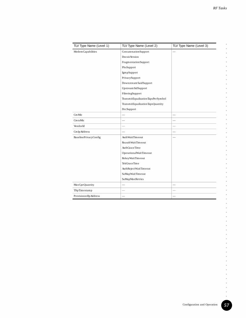
••••••••••••••••••••••••••••••••••••••••••••••••••••••••••
Configuration and Operation
RF Tasks
57
ModemCapabilities ConcatenationSupport
DocsisVersion
FragmentationSupport
PhsSupport
IgmpSupport
PrivacySupport
DownstreamSaidSupport
UpstreamSidSupport
FilteringSupport
TransmitEqualizationTapsPerSymbol
TransmitEqualizationTapsQuantity
DccSupport
—
CmMic — —
CmtsMic — —
VendorId — —
CmIpAddress — —
BaselinePrivacyConfig AuthWaitTimeout
ReauthWaitTimeout
AuthGraceTime
OperationalWaitTimeout
RekeyWaitTimeout
TekGraceTime
AuthRejectWaitTimeout
SaMapWaitTimeout
SaMapMaxRetries
—
MaxCpeQuantity — —
TftpTimestamp — —
ProvisionedIpAddress — —
TLV Type Name (Level 1) TLV Type Name (Level 2) TLV Type Name (Level 3)

RF Tasks
••••••••••••••••••••••••••••••••••••••••••••••••••••••••••
G1 CMTS Installation and Operation58
UpstreamClassificationEncoding ClassifierReference
ClassifierId
ServiceFlowReference
ServiceFlowId
RulePriority
ClassifierActivationState
—
IpPacketClassificationEncoding IpTosRangeAndMask
IpProtocol
IpSourceAddress
IpSourceMask
IpDestinationAddress
IpDestinationMask
TcpUdpSourcePortStart
TcpUdpSourcePortEnd
TcpUdpDestinationPortStart
TcpUdpDestinationPortEnd
EthernetPacketClassificationEncoding DestinationMacAddressAndMask
SourceMacAddress
EthertypeDsapMacType
Ieee8021PQPktClassificationEncoding UserPriority
VlanId
VendorSpecificClassifierParameters —
DownstreamClassificationEncoding ClassifierReference
ClassifierId
ServiceFlowReference
ServiceFlowId
RulePriority
ClassifierActivationState
—
IpPacketClassificationEncoding IpTosRangeAndMask
IpProtocol
IpSourceAddress
IpSourceMask
IpDestinationAddress
IpDestinationMask
TcpUdpSourcePortStart
TcpUdpSourcePortEnd
TcpUdpDestinationPortStart
TcpUdpDestinationPortEnd
EthernetPacketClassificationEncoding DestinationMacAddressAndMask
SourceMacAddress
EthertypeDsapMacType
Ieee8021PQPktClassificationEncoding UserPriority
VlanId
VendorSpecificClassifierParameters —
TLV Type Name (Level 1) TLV Type Name (Level 2) TLV Type Name (Level 3)

••••••••••••••••••••••••••••••••••••••••••••••••••••••••••
Configuration and Operation
RF Tasks
59
UpstreamServiceFlowEncoding ServiceFlowReference
ServiceClassName
QosSetType
TrafficPriority
MaxSustainedTrafficRate
MaxTrafficBurst
MinReservedTrafficRate
MinReservedRatePacketSize
ActiveQosTimeout
AdmittedQosTimeout
MaxConcatenatedBurst
SchedulingType
RequestTransmissionPolicy
NominalPollingInterval
ToleratedPollJitter
UnsolicitedGrantSize
NominalGrantInterval
ToleratedGrantJitter
GrantsPerInterval
IpTosOverwrite
GrantTimeReference
VendorSpecificQosParameters
—
DownstreamServiceFlowEncoding ServiceFlowReference
ServiceClassName
QosSetType
TrafficPriority
MaxSustainedTrafficRate
MaxTrafficBurst
MinReservedTrafficRate
MinReservedRatePacketSize
ActiveQosTimeout
AdmittedQosTimeout
MaxLatency
VendorSpecificQosParameters
—
PayloadHeaderSuppressionEncoding ClassifierReference
ClassifierId
ServiceFlowReference
ServiceFlowIdentifier
DynamicServiceChangeAction
PhsField
PhsIndex
PhsMask
PhsSize
PhsVerification
VendorSpecificPhsParameters
—
MaxNumberOfClassifiers — —
TLV Type Name (Level 1) TLV Type Name (Level 2) TLV Type Name (Level 3)

RF Tasks
••••••••••••••••••••••••••••••••••••••••••••••••••••••••••
G1 CMTS Installation and Operation60
Convert to ASCII File
To convert a binary CM configuration file to an ASCII text file, issue the cable modem-config-file command as follows:
GX$root# cable modem-config-file to-ascii config1.cfg config1.txt
Converts the binary CM configuration file config1.cfg to an ASCII text CM configuration file config1.txt.
Within the ASCII text file, simple TLVs are specified as:
simple-tlv-type-name = <value>
Numeric values can be specified in decimal or hexadecimal (hexadecimal values must be prepended with 0x):
DownstreamFrequency = 62500 orDownstreamFrequency = 0xF424
IP address values can be specified in standard dot-quad notation, in decimal, or hexadecimal (hexadecimal values must be prepended with 0x). Sequences of IP addresses can be separated by spaces or commas:
SubscriberManagementCpeIpTable = 192.168.129.1 192.168.129.2
PrivacyEnable — —
SubscriberManagementControl — —
SubscriberManagementCpeIpTable — —
SubscriberManagementFilterGroups — —
VendorConfig — —
SoftwareUpgradeFilename — —
SnmpWriteAccessControl — —
SnmpMibObject — —
CpeMacAddress — —
SoftwareUpgradeTftpServerIpAddress — —
SnmpV3KickstartValue SecurityName
ManagerPublicNumber
—
TLV Type Name (Level 1) TLV Type Name (Level 2) TLV Type Name (Level 3)

••••••••••••••••••••••••••••••••••••••••••••••••••••••••••
Configuration and Operation
RF Tasks
61
String values must be enclosed in quotes:
SoftwareUpgradeFilename = “upgrade5”
Sequence values can be specified in decimal or hexadecimal (hexadecimal values must be prepended with 0x), and can be separated by spaces or commas:
VendorId = 0x00 0x01 0x02
Single-line comments are signified by the usage of # as the first non-blank character on a line. A commented line is ignored during the conversion of an ASCII text file to a binary configuration file.
Composite TLVs are specified as a list of simple and composite TLVs (the indentation of types is not required, but is recommended for readability):
composite-tlv-type-name {simple-tlv-type-name = <value> simple-tlv-type-name = <value>..composite-tlv-type-name {
simple-tlv-type-name = <value> simple-tlv-type-name = <value>..}
}

RF Tasks
••••••••••••••••••••••••••••••••••••••••••••••••••••••••••
G1 CMTS Installation and Operation62
Following is an example of a binary CM configuration file converted to an ASCII text file:
DownstreamFrequency = 62500
UpstreamChannelId = 1
NetworkAccessControl = 1
ModemCapabilities {
ConcatenationSupport = 0
DocsisVersion = 0
FragmentationSupport = 0
PhsSupport = 0
IgmpSupport = 0
PrivacySupport = 0
DownstreamSaidSupport = 0
UpstreamSidSupport = 0
FilteringSupport = 0
DccSupport = 1
}
VendorId = 0x00 0x01 0x02
CmIpAddress = 192.167.138.5
BaselinePrivacyConfig {
AuthWaitTimeout = 1
ReauthWaitTimeout = 1
AuthGraceTime = 1
OperationalWaitTimeout = 1
RekeyWaitTimeout = 1
TekGraceTime = 1
AuthRejectWaitTimeout = 1
}
MaxCpeQuantity = 1
TftpTimestamp = 123455
ProvisionedIpAddress = 192.168.5.67
UpstreamClassificationEncoding {
ClassifierReference = 1
ServiceFlowReference = 1
RulePriority = 3
ClassifierActivationState = 0
}
DownstreamServiceFlowEncoding {
ServiceFlowReference = 3
QosSetType = 7
TrafficPriority = 0
}
UpstreamServiceFlowEncoding {
ServiceFlowReference = 1
QosSetType = 1
TrafficPriority = 3
SchedulingType = 2
AdmittedQosTimeout = 0
ActiveQosTimeout = 0
}
PrivacyEnable = 1

••••••••••••••••••••••••••••••••••••••••••••••••••••••••••
Configuration and Operation
RF Tasks
63
SubscriberManagementCpeIpTable = 192.167.139.1 192.167.139.2
192.167.139.3
SoftwareUpgradeFilename = "upgrade5"
SoftwareUpgradeTftpServerIpAddress = 192.45.67.89
SnmpV3KickstartValue {
SecurityName = "LOW SECURITY"
ManagerPublicNumber = 0x02 0xe8 0xff 0xbf 0x20 0x20 0x20
}
SnmpV3KickstartValue {
SecurityName = "HIGH SECURITY"
ManagerPublicNumber = 0x19 0xe8 0xff 0xbf 0x20 0x20 0x20
}
CpeMacAddress = 0x01 0x02 0x03 0x04 0x05 0x06
# CmMic = 0x18 0x32 0xd1 0x2a 0x6c 0xfe 0xf4 0xbd 0x99 0xbf 0x56 0xb6
0x24 0x8e 0xbd 0x67
# CmtsMic = 0x5b 0xf1 0x9f 0x1a 0xa6 0x58 0xe9 0x38 0x0e 0x3f 0xf3
0x12 0xc7 0xeb 0x05 0x82
Edit the ASCII File
To edit the ASCII text file, used the edit command as follows:
GX$root# edit config1.txt
Create the Binary File
To convert the ASCII text file to a binary CM configuration file, issue the cable modem-config-file command as follows:
GX$root# cable modem-config-file generate-from-ascii config1.txt config1.cfg
Converts the ASCII text CM configuration file config1.txt to a binary CM configuration file config1.cfg.
Display the Binary File
To display a binary CM configuration file, issue the cable modem-config-file command as follows:
GX$root# cable modem-config-file show config1.cfg
NSI Tasks
••••••••••••••••••••••••••••••••••••••••••••••••••••••••••
G1 CMTS Installation and Operation64
NSI Tasks
This section describes those tasks associated with the Network Side Interface (NSI) functions of the G1 CMTS, such as configuring DHCP and SNMP server parameters.
DHCP Server Parameters
The CLI is used to configure the CMTS with various parameters associated with the Dynamic Host Control Protocol (DHCP):
! The cable dhcp-giaddr and the giaddr commands are used to specify both the IP address for the associated cable interface as well as the IP address to be used as the GIADDR when relaying DHCP requests. The GIADDR configured for a cable interface is owned by the CMTS. This enables the CMTS to directly receive the DHCP message responses sent by the DHCP server. The CMTS will respond to ARP requests for this IP address.
Multiple GIADDRs (up to 16) can be configured for the CPE devices, in which case the relay agent uses a round robin algorithm to assign the GIADDR address to CPE device DHCP Discover/Request messages. Multiple GIADDRs are configured to distribute the CPE devices evenly within all the multiple subnets behind a single cable interface.
! The cable helper-address and the helper-address commands are used to specify the IP address of the DHCP server. If the DHCP server is not on a directly-attached subnet to the Fast Ethernet port to which the DHCP traffic is being forwarded, the next-hop parameter must also be specified.
! The cable relay-agent-option and relay-agent-option commands are used to enable the CMTS to insert DHCP relay information in DHCP-Bootrequest messages forwarded by a CM or CPE to DHCP servers. Specifically, the CMTS inserts the 48-bit MAC address of the CM in the "DHCP Relay Agent Information Option, sub-option Agent Circuit ID" (option 82) field. The DHCP server uses this address and the one in the DHCP-Bootrequest message to determine if the original request came from a CM or CPE.
! The cable subscriber-group command is used to define a subscriber group.
To avoid potential issues with network side equipment, we recommend that you assign different subnet GIADDRs to different cable interfaces.

••••••••••••••••••••••••••••••••••••••••••••••••••••••••••
Configuration and Operation
NSI Tasks
65
Subscriber Groups
A subscriber group is a collection of CMs and CPEs. All CMs and CPEs that reside in the same subscriber group use the DHCP-related parameters assigned while in the subscriber group sub-mode. These parameters are assigned with the subscriber group sub-mode commands dhcp-giaddr, helper-address, and relay-agent-option. The basic underlying functionality of these commands is the same as the cable dhcp-giaddr, cable helper-address, and cable relay-agent-option commands, respectively.
Any DHCP configuration performed at the interface cable sub-mode level applies to what is known as the default subscriber group for that cable interface.
DHCP Server Configurations
This section presents three different DHCP server configurations that can be used to distinguish between CM and CPE DHCP-Bootrequest messages, and the CLI command sequence used to support these configurations.
1. In this configuration, assume a DHCP server is configured to distinguish between CMs and CPEs through the relay agent option (option 82). The G1 CMTS will broadcast all CM and CPE broadcast DHCP-Bootrequest messages from slot/if to the network using the relay agent option (see “DHCP-Bootrequest Broadcasting” on page 66 for more information).
GX$root# configure terminal
GX$root(config)# interface cable <slot/if>GX$root(config-if-cslot/if)# cable relay-agent-option
2. In this configuration, assume the same DHCP server is used for CMs and CPEs, but the distinction between them is made by assigning different GIADDRs for CMs and CPEs. The G1 CMTS will broadcast all CM and CPE broadcast DHCP-Bootrequest messages from slot/if to the network using their respective GIADDRs (see “DHCP-Bootrequest Broadcasting” on page 66 for more information).
GX$root# configure terminal
GX$root(config)# interface cable <slot/if>GX$root(config-if-cslot/if)# cable dhcp-giaddr 10.0.0.1 cable-modemGX$root(config-if-cslot/if)# cable dhcp-giaddr 172.0.0.1 host
Every subscriber group created on a cable interface must be assigned a cable modem GIADDR, and the IP address used must be from the same subnet assigned to the CMs in that subscriber group.

NSI Tasks
••••••••••••••••••••••••••••••••••••••••••••••••••••••••••
G1 CMTS Installation and Operation66
3. This configuration is similar to the previous one in that different GIADDRs are assigned for CMs and CPEs. Moreover, one DHCP server is dedicated to CMs, and another is dedicated to CPEs. The G1 CMTS will forward all CM and CPE broadcast DHCP-Bootrequest messages from slot/if as unicast messages to the DHCP servers at IP addresses 192.168.6.101 and 192.168.6.103, respectively, using their respective GIADDRs.
GX$root# configure terminal
GX$root(config)# interface cable <slot/if>GX$root(config-if-cslot/if)# cable dhcp-giaddr 10.0.0.1 cable-modemGX$root(config-if-cslot/if)# cable dhcp-giaddr 172.0.0.1 hostGX$root(config-if-cslot/if)# cable helper-address 192.168.6.101 cable-modemGX$root(config-if-cslot/if)# cable helper-address 192.168.6.103 host
DHCP-Bootrequest Broadcasting
A CM broadcast DHCP-Bootrequest message is forwarded by the G1 CMTS relay agent to all subscriber groups configured on the associated cable interface, including the default subscriber group. One and only one subscriber group should respond to provision the CM with an IP address from the pool of addresses belonging to that group. Responses from more than one subscriber group can lead to unpredictable IP address assignment. When the CM has successfully been assigned an IP address from the DHCP server response, the G1 CMTS relay agent records the association between the CM and its subscriber group. Thereafter, a CPE broadcast DHCP-Bootrequest message is forwarded as a unicast message by the G1 CMTS relay agent only to the associated CM’s subscriber group that was recorded during the CM’s registration.
If a CM’s subscriber group is deleted by the operator, the CM is made part of the default subscriber group for its cable interface. All CPE broadcast DHCP-Bootrequest messages are then handled based on the configuration for the default subscriber group.
DHCP Provisioning Scenarios
This section provides four different provisioning scenarios that apply to supporting multiple subscriber groups, where a subscriber group can correspond to an Internet Service Provider (ISP).
1. This scenario assumes that two ISPs on a cable interface share a single DHCP server on a subnet different than the subnet of the Fast Ethernet port associated with this cable interface. The ISPs use different subnets from each other, and use different subnets for CMs and CPEs.
Configuration:
Common DHCP server IP address: 192.168.23.45
ISP1 next hop IP address: 10.22.3.1ISP1 CM subnet: 10.22.3.4ISP1 CPE subnet: 172.17.18.1
ISP2 next hop IP address: 10.22.4.1ISP2 CM subnet: 10.22.4.4ISP2 CPE subnet: 162.15.14.1

••••••••••••••••••••••••••••••••••••••••••••••••••••••••••
Configuration and Operation
NSI Tasks
67
GX$root# configure terminal
GX$root(config)# interface cable <slot/if>GX$root(config-if-cslot/if)# cable subscriber-group ISP1GX$root(config-if-cslot/if-sgrp)# helper-address 192.168.23.45 10.22.3.1GX$root(config-if-cslot/if-sgrp)# dhcp-giaddr 10.22.3.4 cable-modemGX$root(config-if-cslot/if-sgrp)# dhcp-giaddr 172.17.18.1 hostGX$root(config-if-cslot/if-sgrp)# exitGX$root(config-if-cslot/if)# cable subscriber-group ISP2GX$root(config-if-cslot/if-sgrp)# helper-address 192.168.23.45 10.22.4.1GX$root(config-if-cslot/if-sgrp)# dhcp-giaddr 10.22.4.4 cable-modemGX$root(config-if-cslot/if-sgrp)# dhcp-giaddr 162.15.14.1 host
2. This scenario assumes that two ISPs on a cable interface use a different DHCP server on a subnet different than the subnet of the Fast Ethernet port associated with this cable interface. The ISPs use different subnets from each other, and use different subnets for CMs and CPEs.
Configuration:
ISP1 DHCP server IP address: 192.16.2.4ISP1 next hop IP address: 10.22.3.1ISP1 CM subnet: 10.22.3.4ISP1 CPE subnet: 172.17.18.1
ISP2 DHCP server IP address: 192.17.3.7ISP2 next hop IP address: 10.22.4.1ISP2 CM subnet: 10.22.4.4ISP2 CPE subnet: 162.15.14.1
GX$root# configure terminal
GX$root(config)# interface cable <slot/if>GX$root(config-if-cslot/if)# cable subscriber-group ISP1GX$root(config-if-cslot/if-sgrp)# helper-address 192.16.2.4 10.22.3.1GX$root(config-if-cslot/if-sgrp)# dhcp-giaddr 10.22.3.4 cable-modemGX$root(config-if-cslot/if-sgrp)# dhcp-giaddr 172.17.18.1 hostGX$root(config-if-cslot/if-sgrp)# exitGX$root(config-if-cslot/if)# cable subscriber-group ISP2GX$root(config-if-cslot/if-sgrp)# helper-address 192.17.3.7 10.22.4.1GX$root(config-if-cslot/if-sgrp)# dhcp-giaddr 10.22.4.4 cable-modemGX$root(config-if-cslot/if-sgrp)# dhcp-giaddr 162.15.14.1 host
3. This scenario assumes that two ISPs on a cable interface use different DHCP servers on a subnet different than the subnet of the Fast Ethernet port associated with this cable interface. The ISPs use different subnets from each other, and ISP2 uses different subnets for CMs and CPEs. ISP1 uses the relay agent option to distinguish between CMs and CPEs, whereas ISP2 uses a different DHCP server for CMs and CPEs. Furthermore, ISP2 wants to assign all CPEs on the cable interface across multiple CPE subnets.
Configuration:
ISP1 DHCP server IP address: 192.16.2.4ISP1 next hop IP address: 10.22.3.1ISP1 CM and CPE subnet: 10.22.3.4ISP1 uses relay agent option

NSI Tasks
••••••••••••••••••••••••••••••••••••••••••••••••••••••••••
G1 CMTS Installation and Operation68
ISP2 CM DHCP server IP address: 192.17.3.7ISP2 CM next hop IP address: 10.22.4.1ISP2 CPE DHCP server IP address: 192.17.3.8ISP2 CPE next hop IP address: 162.15.14.1ISP2 CM subnet: 10.22.4.4ISP2 CPE subnets: 162.15.14.6, 162.16.14.6, 162.17.14.6
GX$root# configure terminal
GX$root(config)# interface cable <slot/if>GX$root(config-if-cslot/if)# cable subscriber-group ISP1GX$root(config-if-cslot/if-sgrp)# helper-address 192.16.2.4 10.22.3.1GX$root(config-if-cslot/if-sgrp)# dhcp-giaddr 10.22.3.4GX$root(config-if-cslot/if-sgrp)# relay-agent-optionGX$root(config-if-cslot/if-sgrp)# exitGX$root(config-if-cslot/if)# cable subscriber-group ISP2GX$root(config-if-cslot/if-sgrp)# helper-address 192.17.3.7 10.22.4.1 cable-modem
GX$root(config-if-cslot/if-sgrp)# helper-address 192.17.3.8 162.15.14.1 hostGX$root(config-if-cslot/if-sgrp)# dhcp-giaddr 10.22.4.4 cable-modemGX$root(config-if-cslot/if-sgrp)# dhcp-giaddr 162.15.14.6 hostGX$root(config-if-cslot/if-sgrp)# dhcp-giaddr 162.16.14.6 hostGX$root(config-if-cslot/if-sgrp)# dhcp-giaddr 162.17.14.6 host
In this scenario, the GIADDRs 162.15.14.6, 162.16.14.6, and 162.17.14.6 are used by the G1 CMTS relay agent in a round robin algorithm to assign the GIADDRs to CPE device DHCP Discover/Request messages for ISP2.
4. This scenario assumes that there are two ISPs on a cable interface. ISP1 uses the relay agent option to broadcast DHCP-Bootrequest messages and to distinguish between CMs and CPEs. ISP1 specifies a GIADDR only for CMs. ISP2 uses a different DHCP server for CMs and CPEs. These servers reside on a subnet different than the subnet of the Fast Ethernet port associated with this cable interface. ISP2 uses different subnets for CMs and CPEs.
Configuration:
ISP1 CM subnet: 10.22.3.4ISP1 uses relay agent option
ISP2 CM DHCP server IP address: 192.17.3.7ISP2 CM next hop IP address: 10.22.4.1ISP2 CPE DHCP server IP address: 192.17.3.8ISP2 CPE next hop IP address: 162.15.14.1ISP2 CM subnet: 10.22.4.4ISP2 CPE subnets: 162.15.14.6
GX$root# configure terminal
GX$root(config)# interface cable <slot/if>GX$root(config-if-cslot/if)# cable subscriber-group ISP1GX$root(config-if-cslot/if-sgrp)# dhcp-giaddr 10.22.3.4GX$root(config-if-cslot/if-sgrp)# relay-agent-optionGX$root(config-if-cslot/if-sgrp)# exitGX$root(config-if-cslot/if)# cable subscriber-group ISP2GX$root(config-if-cslot/if-sgrp)# helper-address 192.17.3.7 10.22.4.1 cable-modem
GX$root(config-if-cslot/if-sgrp)# helper-address 192.17.3.8 162.15.14.1 hostGX$root(config-if-cslot/if-sgrp)# dhcp-giaddr 10.22.4.4 cable-modemGX$root(config-if-cslot/if-sgrp)# dhcp-giaddr 162.15.14.6 host

••••••••••••••••••••••••••••••••••••••••••••••••••••••••••
Configuration and Operation
NSI Tasks
69
Shared Secret
To specify a shared secret, which is an authentication string that is shared between a server that provides a cable modem’s configuration file and the CMTS, use the cable shared-secret command as follows:
GX$root# configure terminal
GX$root(config)# cable shared-secret mysecret
The shared secret authentication string for the entire CMTS is mysecret.
A shared secret can be specified as an encrypted string:
GX$root(config)# cable shared-secret 977071536c2ea956 encrypted
The encrypted shared secret authentication string for the entire CMTS is 977071536c2ea956.
A shared secret can also be specified on a cable interface basis:
GX$root(config)# interface cable <slot/if>GX$root(config-if-cslot/if)# cable shared-secret int1secret
The shared secret authentication string for slot/if is int1secret.
SNMP Server Parameters
To specify the SNMP password community read-write and read-only strings, use the snmp-server community command as follows:
GX$root# configure terminal
GX$root(config)# snmp-server community myrwpw rw
Establishes myrwpw as the read-write SNMP password community string.
GX$root(config)# snmp-server community myropw ro
Establishes myropw as the read-only SNMP password community string.
To specify the destination host(s) that will receive SNMP traps, use the snmp-server host command as follows:
GX$root(config)# snmp-server host 205.15.128.132 version 2c
Specify an IP address of 205.15.128.132 for the SNMP server. The SNMP version that will be used to send traps is 2c. The UDP port to which traps will be sent on this host is 162.
The snmp-server host command specifies the destination hosts that will receive SNMPv1 and SNMPv2c traps from the CMTS. Up to 10 SNMPv1 and up to 10 SNMPv2c destinations can be specified. An alternative way to specify trap destinations for SNMPv1, SNMPv2c, and SNMPv3 is to use the SNMP-TARGET-MIB tables. Those tables are distinct from the tables acted upon by the snmp-server host command. To avoid confusion, it might be advantageous to set up SNMP trap destination hosts either via the SNMP-TARGET-MIB tables or the snmp-server host command, but not both.

NSI Tasks
••••••••••••••••••••••••••••••••••••••••••••••••••••••••••
G1 CMTS Installation and Operation70
Domain Name Server Address
To specify the IP address of a domain name system (DNS) server, use the ip name-server command as follows:
GX$root# configure terminal
GX$root(config)# ip name-server 192.16.90.1
GX$root(config)# ip name-server 192.16.90.2
Adds the DNS servers at addresses 192.16.90.1 and 192.16.90.2. The CMTS will then consult these addresses, in that order, when resolving a host name.
File and Directory Management
To display a directory, use either the dir command or the ls command as follows:
GX$root> dir /home
GX$root> ls /home
Each of these two commands displays the contents of the directory home.
To display the root directory, use either the dir command or the ls command as follows:
GX$root> dir /
GX$root> ls /
Each of these two commands displays the contents of the directory root.
To display the current directory, use the pwd command as follows:
GX$root> pwd
To change the current directory, use the cd command as follows:
GX$root> cd temp
The command prompt location is changed to the temp directory using a relative path. The temp directory must be under the current location.
GX$root> cd /home/temp
The command prompt location is changed to the temp directory using an absolute path.
Use the mkdir command to create a new directory as follows:
GX$root# cd /samples/data
GX$root# mkdir logs
Creates a new directory named logs in the path sample/data.
Use the rmdir command to delete a directory as follows:
GX$root# rmdir /logs
Deletes the directory named logs in the current path.

••••••••••••••••••••••••••••••••••••••••••••••••••••••••••
Configuration and Operation
NSI Tasks
71
Configuration Management
To view the current configuration of the G1 CMTS, issue the following command:
GX$root# show running-config
To save the current configuration of the G1 CMTS, issue the following command. Upon booting up, the system uses the startup-config file to set the configuration:
GX$root# copy running-config startup-config
To store all persistent configuration data—including the user database, the CLI configuration, and the SNMPv3 configuration—use the system config-backup command as follows:
GX$root# system config-backup mycfg.cli
Saves the current configuration in mycfg.cli in the current directory.
To restore a previously-saved configuration, use the system restore-backup command as follows:
GX$root# system restore-backup mycfg.cli
Restores the CMTS to the configuration defined in mycfg.cli after the next reboot.
Ping and Traceroute
Use the ping command at the top level to ping an IP address as follows:
GX$root> ping 100.205.50.150
Verifies the connection between the CMTS and the device at IP address 100.205.50.150.
To trace a connection to a specified IP address, use the traceroute command as follows:
GX$root> traceroute 172.164.70.13

NSI Tasks
••••••••••••••••••••••••••••••••••••••••••••••••••••••••••
G1 CMTS Installation and Operation72

••••••••••••••••••••••••••••••••••••••••••••••••
73
Part 2Troubleshooting and Maintenance
! RF Measurements on page 75
! Troubleshooting on page 83
! Upgrades on page 105

••••••••••••••••••••••••••••••••••••••••••••••••••••••••••
G1 CMTS Installation and Operation74

••••••••••••••••••••••••••••••••••••••••••••••••
RF Measurements 75
Chapter 5RF Measurements
This chapter provides the procedures for measuring the downstream and upstream RF signals of the G1 CMTS using a spectrum analyzer. These procedures can be followed immediately after the initial installation and configuration of the G1 CMTS to ensure the system is configured and operating properly. In addition, these procedures can assist with the diagnosis of RF issues that are detected by spectrum monitoring applications such as the ServiceGuard Management System (see “ServiceGuard Management System” on page 94).
The following procedures assume the use of a Hewlett Packard HP8591C CATV Analyzer, but any equivalent spectrum analyzer will suffice.
Downstream RF Measurement in CATV Mode
This section describes the procedure for measuring the downstream signal power from the G1 CMTS using CATV mode on the HP8591C CATV Analyzer. If your spectrum analyzer does not support CATV mode, you can use the SPECTRUM ANALYZER mode as described in “Downstream RF Measurement in Spectrum Analyzer Mode” on page 77.
1. Connect the spectrum analyzer to a cable within the plant that carries the downstream signal you are measuring. The signal originates from one of the downstream ports of the G1 CMTS (DS0 or DS1).
2. View (or set) the output RF power level of the specific channel to be measured. In this example, the output RF power level for channel 0 is set to 61 dBmV. The power specified in the cable downstream rf-power command can be viewed by issuing the show running-config command, or alternatively by using SNMP.
GX$root# show running-config
continued...interface
cable 2/0 cable downstream 0 channel-width 6000000 cable downstream 0 frequency 531000000 cable downstream 0 interleave-depth 8 cable downstream 0 modulation 64qam cable downstream 0 rf-power 61 no cable downstream 0 shutdown
continued...
This command displays the current configuration. Look for the channel downstream <channel> rf-power <power-level> output to determine the power level specified for the downstream channel.

Downstream RF Measurement in CATV Mode
••••••••••••••••••••••••••••••••••••••••••••••••••••••••••
G1 CMTS Installation and Operation76
To set the output RF power level, use the cable downstream rf-power command as follows:
GX$root# configure terminal
GX$root(config)# interface cable <slot/if>GX$root(config-if-cslot/if)# cable downstream 0 rf-power 61
3. Press the MODE key and set the spectrum analyzer to CABLE TV ANALYZER mode.
4. Select CHANNEL MEAS (channel measurement) and enter the desired channel number. In this example, channel 75 is selected, which corresponds to a center frequency of 531 MHz.
5. Navigate to the third menu on the screen and select DIGITAL POWER. The spectrum analyzer display should be similar to the display in Figure 15.
6. Ensure that the DIGITAL CHANNEL POWER shown at the bottom of the display is approximately equal to the set downstream power level, minus any attenuation between the G1 CMTS downstream port and the point at which your measurement is taken in the cable plant. In this example, the attentuation between the CMTS and the measurement point was approximately 13 dB. Therefore, the expected measured value should be approximately 48 dBmV.
Figure 15: Downstream RF Signal (CATV Mode)

••••••••••••••••••••••••••••••••••••••••••••••••••••••••••
RF Measurements
Downstream RF Measurement in Spectrum Analyzer Mode
77
Downstream RF Measurement in Spectrum Analyzer Mode
This section describes the procedure for measuring the downstream signal power from the G1 CMTS using the SPECTRUM ANALYZER mode on the HP8591C CATV Analyzer.
1. Connect the spectrum analyzer to a cable within the plant that carries the downstream signal you are measuring. The signal originates from one of the downstream ports of the G1 CMTS (DS0 or DS1).
2. View (or set) the output RF power level of the specific channel to be measured. In this example, the output RF power level for channel 0 is set to 61 dBmV. The power specified in the cable downstream rf-power command can be view by issuing the show running-config command, or alternatively by using SNMP.
GX$root# show running-config
continued...interface
cable 2/0 cable downstream 0 channel-width 6000000 cable downstream 0 frequency 531000000 cable downstream 0 interleave-depth 8 cable downstream 0 modulation 64qam cable downstream 0 rf-power 61 no cable downstream 0 shutdown
continued...
This command displays the current configuration. Look for the channel downstream <channel> rf-power <power-level> output to determine the power level specified for the downstream channel.
To set the output RF power level, use the cable downstream rf-power command as follows:
GX$root# configure terminal
GX$root(config)# interface cable <slot/if>GX$root(config-if-cslot/if)# cable downstream 0 rf-power 61
3. Press the MODE key and set the spectrum analyzer to SPECTRUM ANALYZER mode.
4. Press the FREQUENCY key and enter the desired frequency. In this example, 531 MHz is entered.
5. Press the SPAN key and enter 6 MHz.
6. Press the BW key and turn video averaging on by selecting VID AVG ON. The default number of averages is 100. The number of averages can be changed by using the numeric keypad.

Downstream RF Measurement in Spectrum Analyzer Mode
••••••••••••••••••••••••••••••••••••••••••••••••••••••••••
G1 CMTS Installation and Operation78
7. Press the MKR FCTN key (marker function) and select MK NOISE ON. This sets the spectrum analyzer to read out the power bandwidth, normalized to 1 Hz. The spectrum analyzer display should be similar to the display in Figure 16 on page 78.
8. The power shown on the display in Figure 16—shown in two places, on the top/right and middle/left—is –19.12 dBmV, at 1 Hz. In order to obtain the power in the 6 MHz channel, a correction factor is required. This correction factor equals 10 log(ChannelBW/measurementBW). In this case, 10 log (6x10^6/1) equals 67.78 dB. Therefore, the actual downstream channel power equals (-19.12+67.78), which equals 48.66 dBmV. Ensure that this power value is approximately equal to the set downstream power level, minus any attenuation between the G1 CMTS downstream port and the point at which your measurement is taken in the cable plant. In this example, the attentuation between the CMTS and the measurement point was approximately 13 dB. Therefore, the expected measured value should be approximately 48 dBmV.
Figure 16: Downstream RF Signal (Spectrum Analyzer Mode)

••••••••••••••••••••••••••••••••••••••••••••••••••••••••••
RF Measurements
Upstream RF Measurement
79
Upstream RF Measurement
This section describes the procedure for measuring an upstream signal to the G1 CMTS using zero span mode on the HP8591C CATV Analyzer.
1. Connect the spectrum analyzer to a cable within the plant that carries the upstream signal(s) you are measuring. The signals are received on one of the upstream ports of the G1 CMTS (US0 through US3).
2. Press the FREQ key and enter the center frequency that corresponds to the upstream frequency you are measuring. In this example, the upstream frequency is 9 MHz. The upstream channel frequency can be viewed by issuing the show running-config CLI command, or alternatively by using SNMP.
GX$root# show running-config
continued...cable upstream 0 channel-width 1600000cable upstream 0 data-backoff 3 10cable upstream 0 frequency 9000000cable upstream 0 minislot-size 8
continued...
This command displays the current configuration. Look for the channel upstream <channel> frequency <frequency> output to determine the frequency specified for the upstream channel.
3. Press the SPAN key and enter 0 MHz (or select ZERO SPAN). This sets the spectrum analyzer to zero span mode, where signals will be displayed in the time domain.
4. Press the BW key (Bandwidth), select RES BW MAN (Resolution Bandwidth Manual), and enter 3 MHz.
5. While in the BW key menu, select VID BW MAN (Video Bandwidth Manual), and enter 3 MHz.
6. Press the AMPLITUDE key, select ATTEN MAN (Attenuation Manual), and enter 0 dB. This removes all internal spectrum analyzer attenuation.
7. While still in the AMPLITUDE screen, select REF LVL (Reference Level), and enter a value slightly greater than the maximum power level you are expecting. The reference level is the power represented by the top graticule line in the display. In this example, the reference level is set to 5 dBmV.
8. Select SCALE and adjust the scale so that the signal spans the entire Y-axis of the display.
9. Press the TRIG key (Trigger), select VIDEO, and adjust the trigger line to within one graticule of the peak of the signal.
DOCSIS specifies that cable modems use TDMA (Time Division Multiple Access) for upstream transmissions, which means that cable modems are not continuously transmitting. In order to facilitate the triggering and capture of upstream signals, the cable modems should be transmitting long packets as often as possible.

Upstream RF Measurement
••••••••••••••••••••••••••••••••••••••••••••••••••••••••••
G1 CMTS Installation and Operation80
10. Press the SWEEP key, select SWP TIME MAN (Sweep Time Manual), and set the sweep time to a value in the range of 80–100 µs.
11. Press the SGL SWP key (Single Sweep) repeatedly until the spectrum analyzer display is similar to the display in Figure 17 on page 80. The first three graticule columns represent the upstream burst transmission of a single cable modem, including the preamble.
12. Press the MKR (Marker) key and adjust the marker to a position on the signal that represents the median power level of the signal. In Figure 17, the marker is approximately positioned at a median level of 0.65 dBmV. Ensure that this power level is equal to the expected receive power level of the CMTS plus any attenuation between the CMTS and the point of measurement. The upstream channel power level can be viewed by issuing the show running-config CLI command:
GX$root# show running-config
continued...cable upstream 0 port 0cable upstream 0 power-level 0cable upstream 0 range-backoff 1 5
continued...
This command displays the current configuration. Look for the channel upstream <channel> power-level <power-level> output to determine the power level specified for the upstream channel.
Figure 17: Single Upstream Burst
Figure 18 on page 81 represents the spectrum analyzer display of multiple upstream bursts. This display was produced by following the previous procedure with the following modifications: the reference level in step 7 was set to 10 dBmV, and the sweep time in step 10 was set to 20 msec.

••••••••••••••••••••••••••••••••••••••••••••••••••••••••••
RF Measurements
Upstream RF Measurement
81
Figure 18: Multiple Upstream Bursts

Upstream RF Measurement
••••••••••••••••••••••••••••••••••••••••••••••••••••••••••
G1 CMTS Installation and Operation82

••••••••••••••••••••••••••••••••••••••••••••••••
Troubleshooting 83
Chapter 6Troubleshooting
This chapter identifies common issues associated with the operation and configuration of the G1 CMTS, the HFC plant, and CM provisioning. Recommendations for troubleshooting and resolving these issues using the flap-list and debug features of the G1 CMTS are also provided. For purposes of discussion, HFC Plant refers to all cabling and equipment on the RF side of the network, other than the CMTS, regardless of its physical location.
Features for Troubleshooting
The G1 CMTS provides powerful features that aid you with troubleshooting CMTS, CM, and HFC plant related issues, including the flap-list, the local event log, debug commands, and various CLI commands that display relevant statistics.
Flap-List
To assist with diagnosing issues that can affect CM ranging, registration, operation, or data throughput, the G1 CMTS maintains a database of CMs along with various modem statistics for each CM. When a CM exhibits behavior that matches pre-defined criteria—referred to as a flap—an entry is added to a table called a flap-list. Each flap-list entry contains the MAC address of the CM, along with additional modem statistics that can assist in determining why the CM flapped.
The flap criteria are defined globally for all cable interfaces by setting various parameters (thresholds) within the cable modem flap-list command. If a parameter is not explicitly set, a flap is defined by its default value. The global flap thresholds can be overridden on an upstream channel basis by the cable upstream modem flap-list command.
After an entry is added to the flap-list for a CM, any subsequent flap for that CM, whether defined explicitly or by default, updates that flap-list entry with new statistics (including a flap count). Examples of flaps include excessive initial ranging, missed station maintenance opportunities, large upstream power adjustments, and a signal-to-noise ratio (SNR) dropping below a threshold.
We recommend that you review the G1 CMTS release notes for details regarding the latest features, changes, and known and resolved issues. This might assist you with troubleshooting some of the issues you encounter with the operation of your system.

Features for Troubleshooting
••••••••••••••••••••••••••••••••••••••••••••••••••••••••••
G1 CMTS Installation and Operation84
A flap-list can be displayed by issuing the show cable flap-list command. The display is sorted by the specified parameter (see Table 28 for a list of sort parameters).
Table 28: Flap-list Sort Parameter
by-total-flaps Sorts the flap-list in descending order of the Total column.
by-time Sorts the flap-list from most recent (top) to least recent (bottom) i.n the LTime column.
by-snr-flaps Sorts the flap-list in descending order of the SNR column.
by-cer-flaps Sorts the flap-list in descending order of the CER column.
by-mer-flaps Sorts the flap-list in descending order of the MER column.
by-im-flaps Sorts the flap-list in descending order of the IM column.
by-sm-flaps Sorts the flap-list in descending order of the SM column.
by-power-adjust Sorts the flap-list in descending order of the PAdj column.
by-interface If the slot and if parameters are not specified, the flap-list is sorted in ascending order of slot, interface, and port in the CableIF column. See slot and if to see their effect on the sorting.
slot If specified, only the flap-list entries associated with CMs on the DOCSIS Module slot are displayed.
Slot number 2 is the only valid entry.
if If specified, only the flap-list entries associated with CMs on the slot and if are displayed.
Interface (0 or 1)
by-upstream If the slot and channel parameters are not specified, the flap-list is sorted in ascending order of slot, channel, and port in the CableIF column. See slot and channel to see their effect on the sorting.
channel If specified, only the flap-list entries associated with CMs on the slot and channel are displayed.
The upstream channel (0 to 7)
by-mac If specified, only the flap-list entries associated with the CM that has a MAC address of mac-address are displayed.
mac-address MAC address of CM specified as xxxx.xxxx.xxxx in hexadecimal.

••••••••••••••••••••••••••••••••••••••••••••••••••••••••••
Troubleshooting
Features for Troubleshooting
85
The following example displays the flap-list sorted by the total number of flaps (under the column labeled Total).
GX$root# show cable flap-list by-total-flaps
Display the entire flap-list sorted by the total number of flaps (under the column labeled Total).
MacAddr CableIF IM SM PAdj SNR MER CER LTime
LEvnt Total SNRavg MERavg CERavg
0002.0001.2C28 C02/0 U00/0 0 0 72 0 0 0 May 06 15:
18:21 PADJ FLAP 72 34 27 0
0000.CA25.1C4A C02/0 U00/0 0 0 59 0 0 0 May 06 15:
10:42 PADJ FLAP 59 34 28 0
0020.40A7.278C C02/0 U00/0 45 0 3 0 1 0 May 06 15:
23:12 IM FLAP 49 34 12 72
00E0.6F03.1061 C02/0 U00/0 0 0 48 0 0 0 May 06 15:
21:40 PADJ FLAP 48 34 27 0
0050.DAA7.6E12 C02/0 U00/0 1 0 41 0 0 0 May 06 15:
20:11 PADJ FLAP 42 34 27 0
0030.D002.1B6F C02/0 U00/0 0 0 35 0 0 0 May 06 15:
19:57 PADJ FLAP 35 34 28 0
0020.407E.F330 C02/0 U00/0 0 0 16 0 0 0 May 06 15:
25:15 PADJ FLAP 16 34 28 0
Total checked entries 7
Table 29 explains each statistic provided in the flap-list. All thresholds cited in Table 29 are parameters within the cable modem flap-list and cable upstream modem flap-list CLI commands. Table 30 on page 87 explains the flap-list thresholds that can be set within the cable modem flap-list and cable upstream modem flap-list commands. See the G-series CMTS CLI Reference for details regarding all commands related to the flap-list.

Features for Troubleshooting
••••••••••••••••••••••••••••••••••••••••••••••••••••••••••
G1 CMTS Installation and Operation86
Table 29: Flap-list Statistics
Statistic Description
MacAddr The MAC address of the CM that flapped.
CableIF The slot/interface and upstream channel/port on which the flapping CM resides, in the form: Cslot/interface Uchannel/port
IM This counter is incremented when the time between two successive initial maintenance attempts (ranging) by the CM is below the threshold im-retry-interval.
SM This counter is incremented when the number of consecutively missed station maintenance opportunities (ranging) by the CM is above the threshold sm-miss-threshold, and the CMTS subsequently receives a successful ranging request from the CM (this latter condition is required to discern whether the CM is missing station maintenance opportunities or is off-line).
PAdj This counter is incremented when the power adjustment sent to the CM during station maintenance is above the threshold power-adjust-threshold.
SNR This counter is incremented when the measured signal-to-noise ratio (SNR) of the CM drops below threshold snr-threshold.
MER This counter is incremented when the measured modulation error rate (MER) of the CM drops below threshold mer-threshold.
CER This counter is incremented when the measured codeword error rate (CER) of the CM rises above cer-threshold.
LTime The timestamp that indicates when the CM flapped.
LEvnt A description of the type of flap that occurred.
Total This counter represents the total number of flaps that have occurred for the CM.
SNRavg The average SNR for the CM.
MERavg The average MER for the CM.
CERavg The average CER for the CM.

••••••••••••••••••••••••••••••••••••••••••••••••••••••••••
Troubleshooting
Features for Troubleshooting
87
Table 30: Flap-list Thresholds
Use the Flap-List for Troubleshooting
Table 31 summarizes the flap-list statistics and the potential HFC plant issues associated with these statistics. Note that the quantification of the statistics is plant dependent, so general qualifications, such as High and Low, are provided.
Table 31: Flap-list Association to Potential Issues
snr-threshold A flap occurs when the measured SNR of a CM drops below this threshold (specified in dB). The valid range is 1–100 and the default is 18.
mer-threshold A flap occurs when the measured modulation error rate (MER) of a CM drops below this threshold (specified in dB). The valid range is 1–100 and the default is 18.
cer-threshold A flap occurs when the measured codeword error rate (CER) of a CM rises above this threshold (specified in units of 10-6). The CER is the ratio of the number of codewords received with errors, before error correction is attempted, and the total number of codewords received (with and without errors). The valid range is 1–1000000 and the default is 1 (1 x 10⁻⁶).
power-adjust-threshold A flap occurs when the power adjustment sent to the CM during station maintenance is above this threshold (specified in dB). The valid range is 1–100 and the default is 3.
im-retry-interval A flap occurs when the time between two successive initial maintenance attempts by a particular CM is below this threshold (specified in seconds). The valid range is 60–86400 and the default is 180.
sm-miss-threshold A flap occurs when the number of consecutively missed station maintenance opportunities by a particular CM is above this threshold, and the CMTS subsequently receives a successful ranging request from the CM (this latter condition is required to discern whether the CM is missing station maintenance opportunities or is off-line). The valid range is 1–100 and the default is 2.
Statistic Value Potential Issues
IM High ! DHCP server issues
! TFTP server issues
! Configuration file issues
SM High ! Noise
! Ingress
! Impairments such as common path distortion
! Laser clipping distortion
! Attenuation (too large or too small)
CER High (with Low CERavg) ! Impulse noise
CERavg High ! Ingress
! Impulse noise
! Impairments such as common path distortion
! Laser clipping distortion
PAdj High ! High attenuation in the return path
! Changing environmental conditions that affect the return path, such as temperature.
! Improper amplification
! Poor amplifier performance

Features for Troubleshooting
••••••••••••••••••••••••••••••••••••••••••••••••••••••••••
G1 CMTS Installation and Operation88
The following general guidelines should be considered when interpreting the flap-list statistics:
! If the flap-list statistics are the opposite of the values presented in Table 31, the provisioning and the HFC plant conditions are considered satisfactory. Use these values to establish an operational baseline.
! Sorting the flap-list by the total number of flaps, or by a specific flap, can assist with locating problematic nodes in the HFC plant. For example, if the flap-list is sorted by MERavg, and the flap entries with the lowest MERavg values are all within the same CableIF, your diagnostic procedures can focus on a particular area of the return path.
! Sorting the flap-list by MAC address (by-mac) can reveal issues associated with CMs manufactured by the same vendor. This can be determined by inspecting the unique vendor identifier contained in the first 24 bits of the MAC address.
! MERavg provides a good metric for the overall quality of the return path because it is affected by virtually every possible source of QPSK/QAM signal amplitude and phase distortion (as opposed to other metrics that are affected mostly by noise). As such, MERavg can be used to gauge the margin of failure available within a particular upstream channel.
! If the IM value is high and the SM value is low, the CM might be having problems with:
! Initial ranging due to CMTS configuration issues.
! Initial ranging due to HFC plant issues in the forward path or the return path.
! Registration due to provisioning issues.
! Stability issues.
SNRavg Low ! Increase in return path noise due to:
! Amplifier thermal noise
! Fiberoptic link noise
! Ingress
! High attenuation in the return path
MERavg Low Any issues that affect the phase and amplitude of the signal in the return path:
! Noise
! Impairments
! Non-linear distortions (in lasers and amplifiers, for example)
! Linear distortions such as group delay variance
! Quality of CM transmitter
Statistic Value Potential Issues

••••••••••••••••••••••••••••••••••••••••••••••••••••••••••
Troubleshooting
Features for Troubleshooting
89
! If the IM value is low and the SM value is high, the CM is able to successfully register, but there might be intermittent HFC plant issues in the forward path or the return path that cause the CM to unsuccessfully use periodic maintenance opportunities.
! A high PAdj value indicates that a CM’s power adjustment is changing by a significant amount which suggests problems in the return path (see Table 31 on page 87). Comparing PAdj for CMs that reside before and after an amplifier in the return path can provide an indication of amplifier issues. Increasing the power level of an RF signal can lead to laser clipping which results in corrupted codewords as seen by the CMTS. Therefore, a high PAdj value in conjunction with a high CERavg value might provide an indication of laser clipping.
Local Event Log
The local event log of the CMTS corresponds to the docsDevEventTable within the DOCSIS Cable Device MIB (RFC-2669). This log can assist with troubleshooting various issues. The OSSI specification defines required events that a CMTS must support. In addition, the G1 CMTS supports Juniper Networks-specific events (see Appendix D). By default, Juniper Networks-specific event generation is enabled (controlled by the pbcCmtsEventsEnable object in the PBC-CMTS-MIB enterprise MIB). Juniper Networks-specific events are categorized into event classes—ENVMON, CHASSIS, SOFTWARE, ACCESS, CONFIG, DATAPATH, RFINTERFACE, and FLAPLIST. Trap generation for Juniper Networks-specific events is controlled by the pbcCmtsNotificationsControl object in the PBC-CMTS-MIB enterprise MIB. See the G-series CMTS SNMP and Enterprise MIB Specification for more details regarding the enterprise MIBs.
To view the log, issue the show local-log command. Table 32 on page 90 provides the correspondence between the log display headings and the RFC-2669 objects.
GX$root> show local-log
Time shown as : YYYY:MM:DD:HH:MM:SS:DS
Index Date/Time Level Id Description
----- ---------------------- ----------- ---------- ----------------------
7180 2002:08:05:08:13:02:05 information 2539850601 DATAPATH Unverifiable IP add
ress 20.5.1.2 received from CPE MAC 0-1-2-E4-2A-C7. CM MAC 0-90-83-39-BA-CE
7181 2002:08:05:08:13:41:07 information 2539850603 DATAPATH Invalid CPE IP (192
.168.27.96), MAC 0-20-40-7F-4F-CA from CM 0-20-40-7F-4F-CA; address not allocate
d
7182 2002:08:05:08:13:42:04 information 2539850603 DATAPATH Invalid CPE IP (192
.168.27.96), MAC 0-20-40-7F-4F-CA from CM 0-20-40-7F-4F-CA; address not
allocated

Features for Troubleshooting
••••••••••••••••••••••••••••••••••••••••••••••••••••••••••
G1 CMTS Installation and Operation90
Table 32: Local Event Log Headings Displayed
See the DOCSIS OSSI specification and RFC-2669 for more details regarding the docsDevEventTable.
Debug Commands
The debug feature sends informational messages to a Telnet or console session whenever a debug event occurs. Debug event types are defined by CLI debug commands for events such as ranging, registration, and the transmission of certain MAC messages (such as MAP and UCC messages).
Debug messages are enabled by performing the following tasks:
1. Define a list of MAC addresses, service IDs (SIDs), or slot/interfaces (MAC domains) to monitor by using the debug cable interface cable command or the debug cable mac-address command. These are known as debug filters.
2. Define the debug event types to be monitored by issuing the appropriate debug commands (such as debug cable range and debug cable registration).
3. Enable debug message output for the current Telnet or console session by issuing the terminal monitor command.
Display Headings RFC-2669 Object Meaning
Index docsDevEvIndex Relative ordering in the event log.
Date/Time docsDevEvFirstTime The time the entry was created.
Level docsDevEvLevel The priority level of the event.
Id docsDevEvId Unique identifier used by the G1 CMTS for the event type.
Description docsDevEvText A text description of the Id.
If no debug filters are defined, all enabled debug event types are monitored, regardless of their associated MAC addresses, SIDs, and slot/interfaces. This can result in a continuous display of debug messages in which case you can enter no terminal monitor (blindly) to stop the display.
Care should be taken when using the debug feature to ensure that the performance of the CMTS is not severely impacted. Restricting the number of CMs and debug events minimizes the resources required to utilize this feature.

••••••••••••••••••••••••••••••••••••••••••••••••••••••••••
Troubleshooting
Features for Troubleshooting
91
Table 33 provides a list of the debug cable command parameters that define the event types to be debugged. For example, the command debug cable range enables the display of debug events associated with initial and station maintenance ranging.
Table 33: Event-defining Debug Command Parameters
The following example illustrates how to enable debugging for DHCP-related activity associated with CMs that reside within the MAC address range of 1234.5678.0000 through 1234.5678.FFFF:
GX$root# debug cable mac-address 1234.5678.ABCD FFFF.FFFF.0000
GX$root# debug cable dhcp
GX$root# terminal monitor
See the G-series CMTS CLI Reference for details regarding the debug commands.
Various CLI Commands
There are some CLI commands that can assist with troubleshooting issues by displaying various types of information, including CM operational states, chassis hardware status, error logs, and configuration data.
Parameter Debug Message Displayed in Association With:
arp Address Resolution Protocol (ARP)
bpkm Baseline Privacy Key Management
bwr Bandwidth Request Frames (REQ)
dcc Dynamic Channel Change
dci Device Class Identification (DCI)
dhcp Dynamic Host Configuration Protocol (DHCP)
dynsrv Dynamic Service Add, Dynamic Service Change, and Dynamic Service Delete messages
icmp Internet Control Message Protocol (ICMP)
mac-protocol MAC layer (bpkm, dcc, dci, dynsrv, range, registration, ucc, updis)
map Upstream Bandwidth Allocation MAP (MAP) messages
range Initial and station maintenance ranging
registration CM registration
ucc Upstream Channel Change (UCC) messages
ucd Upstream Channel Descriptor (UCD) messages
updis Upstream Transmitter Disable (UP-DIS) messages

Features for Troubleshooting
••••••••••••••••••••••••••••••••••••••••••••••••••••••••••
G1 CMTS Installation and Operation92
show cable modem
This command displays the number of CMs that exist in various operational states (if the summary parameter is specified), or displays individual modem information (if the summary parameter is not specified). The command can apply to all CMs, to those CMs in a slot/interface or an upstream channel, or to individual CMs specified by their IP or MAC address.
GX$root> show cable modem 2/1 upstream 2
Displays individual information for each CM in upstream channel 2 in slot 2 / interface 1. See Table 34 for a description of the parameters displayed
Intrfc Prim Online Timing Rec QoS IP-Address MAC-Address Ver Vpn
Sid State Offset Power Id
C2/1/U2 156 online 2481 -2.5 - 192.168.27.101 0010.951D.19B8 1.1
Table 34: Parameters Displayed by ‘show cable modem’ Command
Table 35: Description of Online States
Parameter Description
Intrfc The interface specified as Cslot/if/Uchannel.
Prim Sid The primary service ID (SID) of the CM.
Online State The state of the CM. See Table 35 for a list of these states, then see Table 36 for the correspondence to the CM operational states that can be displayed with the summary option of the show cable modem command.
Timing Offset The timing adjustment provided by the CMTS in a ranging response. Units are (6.25µs/64).
Rec Power The receive power (dBmV) of the CM as detected by the CMTS.
QoS The quality of service (QoS) profile ID.
IP-Address The IP address of the CM.
MAC-Address The MAC address of the CM.
Ver The DOCSIS version of the CM.
Vpn ID The VPN ID to which this CM belongs (if applicable).
State Description
init(r1) The CM has entered the declared state (see Dclr in Table 36).
init(r2) The CM has entered the ranging state (see Rng in Table 36).
init(rc) The CM has entered the ranging-complete state (see Rng Compl in Table 36).
init(i) The CM has entered the IP-complete state (see IP Compl in Table 36).
online The CM has entered the registration-complete state (see Reg in Table 36).
offline The CM is entered the destroyed or ranging-aborted state (see Dstry or Rng Abort, respectively, in Table 36).
reject The CM has entered the access-denied state (see Access Denied in Table 36).

••••••••••••••••••••••••••••••••••••••••••••••••••••••••••
Troubleshooting
Features for Troubleshooting
93
GX$root> show cable modem summary total
Displays the counts and totals for various operational states of all CMs supported by the CMTS. See Table 36 for a description of the operational states displayed.
Cable Modem Operational States
Interface CM Dstry Dclr Rng Rng Rng IP Reg Access
Qty Abort Compl Compl Denied
Cable2/0/U0 230 10 30 10 5 20 10 100 50
Cable2/0/U1 230 10 30 10 5 20 10 100 50
Cable2/0/U4 230 10 30 10 5 20 10 100 50
Cable2/0/U5 230 10 30 10 5 20 10 100 50
Cable2/1/U2 230 10 30 10 5 20 10 100 50
Cable2/1/U3 230 10 30 10 5 20 10 100 50
Cable2/1/U6 230 10 30 10 5 20 10 100 50
Cable2/1/U7 230 10 30 10 5 20 10 100 50
Totals 1840 80 240 80 40 160 80 800 400
Table 36: Description of CM Operational States
Operational State Description
Dstry Number of CMs in destroyed operational state. If a CM goes offline for more than 24 hours, it will be removed from the CMTS. A CM is briefly in this state during the removal process.
Dclr Number of CMs in declared operational state. A CM is in this state right after the CMTS receives the CM’s initial ranging request.
Rng Number of CMs in ranging operational state. A CM is in this state during its initial ranging.
Rng Abort Number of CMs in ranging-aborted operational state. A CM is in this state right after the CMTS aborts the ranging (initial or periodic) in its ranging response.
Rng Compl Number of CMs in ranging-complete operational state. A CM is in this state after it has completed its initial ranging.
IP Compl Number of CMs in IP-complete operational state. A CM is in this state right after the CMTS receives a registration request from the CM containing an IP address (TLV Type 12 or 20). The CM can transition from this state only from the ranging-completed state.
Reg Number of CMs in registration-complete operational state. A CM is in this state right after the CMTS sends an Okay registration response (DOCSIS 1.0) or receives an error-free registration acknowledgment (DOCSIS 1.1) from the CM.
Access Denied Number of CMs in access-denied operational state. A CM is in this state after one of several conditions occurs:
– A CM timed out before responding to an upstream channel change request.– The CMTS responds to a DCI-REQ message with a DCI-RSP message containing a
confirmation code set to reject-permanent.– The CM’s registration process failed.

Features for Troubleshooting
••••••••••••••••••••••••••••••••••••••••••••••••••••••••••
G1 CMTS Installation and Operation94
show tech-support
This command displays the following useful information to assist technical support with troubleshooting:
! The current time
! The current software version and the names of upgrade, normal, and failsafe software packages
! The Chassis Control Module and DOCSIS Module error logs
! The chassis hardware details (equivalent to the show chassis hardware detail command)
! Chassis Control Module memory usage (equivalent to the show memory command)
! The local event log (equivalent to the show local-log command)
! Internal warning and error status logs
! Running configuration (equivalent to the show running-config command)
ServiceGuard Management System
Spectrum monitoring of the HFC return path can be accomplished by using the ServiceGuard Management System. The ServiceGuard Management System provides the headend technician with an integrated tool to monitor and analyze the return path network performance at the G1 CMTS by collecting measurements gathered by the Broadband Cable Processor ASIC, processing them into useful statistical information, and presenting them graphically. Statistics that can be measured and plotted within the ServiceGuard Management System include Noise Power and Noise Power Density, signal-to-noise ratio (SNR), modulation error ratio (MER), and codeword error ratio (CER).
The ServiceGuard Management System incorporates an integrated Impairment Identification tool that allows for unattended monitoring of statistics to characterize compromised performance to a potential cause (such as impulse or burst noise, narrowband ingress, or microreflections).
This application allows a technician to recognize, identify, and troubleshoot issues with the return path. In addition, the technician can use these features to map and allocate spectrum for upstream channels.
The ServiceGuard Management System is an optional tool that is not part of the standard G1 CMTS shipment. A ServiceGuard Management System application must be purchased to take advantage of this powerful diagnostic aid.

••••••••••••••••••••••••••••••••••••••••••••••••••••••••••
Troubleshooting
CMTS Power and Bootup Issues
95
CMTS Power and Bootup Issues
This section lists various issues, along with procedures to resolve them, associated with powering up and booting the CMTS.
CMTS Is Not Powering Up
If it appears that power is not being applied to the CMTS—because you do not hear or see any fans rotating, or do not see any LEDs illuminated—this might be attributed to one or more of the following reasons:
! The power cord is not securely connected to the G1 CMTS and to its respective power source.
! The power source is not turned on.
CMTS Does Not Successfully Boot Up
If you do not get to the login and password prompts, followed by the CLI prompt, the CMTS did not successfully boot up. If the front chassis LEDs remain yellow indefinitely, this indicates the Chassis Control Module’s self test was not successful. In this case, contact Juniper Networks customer support for assistance.
CMTS Does Not Boot Up With the Upgraded Software Release
The system apply upgrade command is used to upgrade the software to a new release following the next reboot. If the system is not using the new release following a reboot (which can be determined by the show version command), it might be because the upgraded software release is not compatible with the existing hardware. In this case, the software running on the CMTS following the reboot is the same release that was running on the CMTS prior to the attempted upgrade.
If this issue occurs, consult with Juniper Networks customer support to determine how to resolve the incompatibility. Viewing the local event log might also provide additional information.

Configuration Issues—Ideal HFC Plant
••••••••••••••••••••••••••••••••••••••••••••••••••••••••••
G1 CMTS Installation and Operation96
CMTS Powers Down
If the CMTS powers down, this might be attributed to one or more of the following reasons:
! Power has been disrupted to the system. See “CMTS Is Not Powering Up” on page 95.
! The power supply in the CMTS has reached its over-temperature shutdown limit.
1. Check the ambient temperature in the headend or hub in which the CMTS resides. The air cooling system might not be fully operative in which case the ambient operating temperature might have exceeded the maximum specification for the G1 CMTS of 40°C. See if an SNMP message was sent to the NMS indicating the temperature of the CMTS exceeded the high threshold as set by the chassis environment ambient-temperature command.
2. Ensure that proper clearance is maintained between the G1 CMTS chassis and its surroundings to allow adequate air ventilation to flow into the air intakes and out of the air exhaust. See “Rack Mounting” on page 29 for clearance details.
3. One or more of the chassis fans might have stopped rotating while the CMTS was operating. If an SNMP message was sent to the NMS, or an entry was added to the event log indicating a fan failure, contact Juniper Networks customer support for assistance.
Configuration Issues—Ideal HFC Plant
This section assumes that the HFC plant is ideal and not contributing to issues associated with the CMs. Following is a list of potential issues and the procedures to resolve them.
“HFC Plant-Related Issues” on page 102 addresses issues associated with problems in the HFC plant.
CM Cannot Successfully Range
If a CM cannot successfully range, this might be attributed to one or more of the following reasons:
! The downstream and upstream channel and port mapping are not properly aligned with the forward and return path topology of the HFC plant. For example, suppose the intent is for a CM to reside in MAC domain 0 (cable interface 0), which contains downstream channel 0 and upstream channels 0 and 1. Its forward and return paths are connected to downstream port 0 and upstream port 0, respectively, of the G1 CMTS. This channel and port assignment is the G1 CMTS default configuration. If the CMTS is manually reconfigured so that upstream channel 0 is moved to port 1 (but still in MAC domain 0), when upstream channel 0 is enabled, the CMTS will be expecting the CM to transmit on port 1, but the CM will be transmitting its ranging-requests on port 0.
! The upstream channel on which the CM resides is not enabled. Issue the no cable upstream shutdown command to enable an upstream channel.
A high IM counter value in the flap-list can be an indication of ranging issues.

••••••••••••••••••••••••••••••••••••••••••••••••••••••••••
Troubleshooting
Configuration Issues—Ideal HFC Plant
97
CM Cannot Establish IP Connectivity
If a CM cannot establish IP connectivity, this might be attributed to one or more of the following reasons:
! The DHCP server could not be accessed because the network is down.
! The DHCP server is down. Ping the DHCP server IP address using the ping command to see if the server is responding.
! The DHCP server parameters are not properly configured within the CMTS. See “DHCP Server Parameters” on page 64 for more information.
A high IM counter value in the flap-list can be an indication of DHCP setup issues.
CM Cannot Successfully Register
If a CM cannot successfully register, this might be attributed to one or more of the following reasons:
! The CM did not receive a configuration file because:
! The TFTP server could not be accessed because the network is down.
! The TFTP server is down.
! The name of the configuration file provided in the DHCP response was incorrect.
! The TFTP server IP address provided in the siaddr field of the DHCP response was incorrect.
! The TFTP server was hosting the maximum number of sessions when the CM requested the configuration file.
! The CMTS indicated an authentication failure in its REG-RSP message because:
! The TFTP Server Timestamp field in the CM’s REG-REQ message differs from the local time maintained by the CMTS by more than the CM Configuration Processing Time (the maximum time for a CM to send a REG-REQ message following the receipt of the configuration file, which must be a minimum of 30 seconds).
! The TFTP Server Provisioned Modem Address field in the CM’s REG-REQ message does not match the requesting CM’s actual address.
! The message integrity check (MIC) was not valid because the shared secret between the CMTS and the provisioning server did not match which results in an authentication failure. See “Shared Secret” on page 69 for more information.
! The message integrity check (MIC) was not valid because the configuration file was modified en route between the provisioning server and the CM.
The CMTS might have made an entry for an authentication failure in the local event log. Issue the show local-log command to display the log.

Configuration Issues—Ideal HFC Plant
••••••••••••••••••••••••••••••••••••••••••••••••••••••••••
G1 CMTS Installation and Operation98
! The CM received a configuration file, but the contents of the file are not valid. Ensure the configuration settings are valid, and are consistent with the DOCSIS specifications.
! The CM timed out waiting for the time of day (TOD) server to respond. Newer CMs continue the registration process while continuing to retry the TOD request. However, some older CMs do not attempt to register if they timeout while waiting for a TOD response. The TOD timeout might occur if the TOD server IP address provided in the DHCP response was incorrect.
A high IM counter value in the flap-list can be an indication of TFTP, configuration file, or registration issues.
CM Throughput is Slow
If the throughput of a CM seems slow, this might be attributed to one or more of the following reasons:
! The DOCSIS 1.0 Class of Service Configuration Setting (for DOCSIS 1.0) or the Upstream Service Flow Configuration Setting and the Downstream Service Flow Configuration Setting fields (DOCSIS 1.1) of the configuration file are limiting the maximum upstream and downstream bandwidth of the CM. If necessary, increase the parameters within these fields in the configuration file to increase the CM’s throughput.
To determine the maximum bandwidth settings for a CM, issue the show cable modem command to acquire the CoS/QoS profile for a CM (CoS for DOCSIS 1.0, QoS for DOCSIS 1.1):
GX$root# show cable modem 0090.833d.5469
Intrfc Prim Online Timing Rec QoS IP-Address MAC-Address Ver Vpn
Sid State Offset Power Id
C2/0/U0 7593 online 1989 0.4 1 192.168.27.131 0090.833D.5469 1.1
In this example, the CM uses QoS profile 1. Then issue the show cable qos profile command to display the characteristics of QoS profile 1:
GX$root# show cable qos profile 1
Service Prio Max Guarantee Max Max tx Create Baseline
class upstream upstream downstream burst by privacy
bandwidth bandwidth bandwidth enable
1 0 1000000 0 10000000 0 cmts no
The CM’s maximum upstream bandwidth is 1 Mb/s, and its maximum downstream bandwidth is 10 Mb/s.

••••••••••••••••••••••••••••••••••••••••••••••••••••••••••
Troubleshooting
Configuration Issues—Ideal HFC Plant
99
! Congestion exists in the upstream.
The approximate upstream channel utilization can be computed by monitoring the ifInOctets object in the “DOCSIS RF Interface” MIB (RFC-2670). The ifInOctets object contains the total number of octets received on an interface, including data packets as well as MAC layer packets, and includes the length of the MAC header. However, this object does not account for the PHY layer overhead—preamble, FEC, and guard time—which consumes a certain percent of the available raw channel bandwidth. The following procedure explains how to compute the approximate upstream channel utilization using an SNMP MIB browser:
1. Set the SNMP polling time to a value large enough to capture a statistically significant amount of upstream traffic. In this example, assume the polling time is 60 seconds.
2. Browse the ifInOctets object for the interface that corresponds to the upstream channel you are measuring. Wait for the value of the object to change and record this value. Assume the value is 33,019,041 octets.
3. Wait 60 seconds for the value of the object to change and record this value. Assume the value is 65,903,162 octets.
4. Subtract the value of the object measured in step 2 from the value measured in step 3 to obtain the number of octets received by the CMTS on this upstream channel over the polling time: (65,903,162–33,019,041=32,884,121 octets).
5. Multiply the value computed in step 4 by 8 (to convert to bits), then divide by the polling time to compute the upstream channel bandwidth (without the PHY overhead): [(32,884,121 octets * 8) / 60 sec]=4,384,549 bps.
6. Compute the maximum available raw bandwidth by multiplying the symbol rate of the channel by the number of bits/symbol. Assume the symbol rate is 2560 Ksym/sec, and the modulation is QPSK (2 bits/symbol), which yields a bandwidth of 5,120,000 bps.
7. Computing the PHY overhead, and hence the channel efficiency, is a non-trivial exercise because it is dependent on the mix of transmissions that use a particular interval usage code, packet sizes, and the modulation profile and mini-slot size of the channel. Using practical values for these variables, assume a channel efficiency of 92% (be aware that the channel efficiency can be lower depending on the assumptions made). Derating the maximum available raw bandwidth of the channel by 92% yields 4,710,400 bps (5,120,000 bps*0.92).
8. The approximate upstream channel utilization can be computed by dividing the measured bandwidth calculated in step 5 by the derated maximum bandwidth calculated in step 7: (4,384,549 / 4,710,400)=93%. This represents a highly utilized channel.

Configuration Issues—Ideal HFC Plant
••••••••••••••••••••••••••••••••••••••••••••••••••••••••••
G1 CMTS Installation and Operation100
Congestion might be attributed to one or more of the following reasons:
! An excessive number of CMs are attached to the DOCSIS Module in the return path of the HFC plant. Review your corporate guidelines to ensure you have not exceeded the maximum number of CMs per G1 CMTS for the modulation profiles being used. If necessary, install additional G1 CMTS systems.
! An excessive number of CMs are assigned to the upstream channel in which the CM transmits. Issue the show cable modem command as follows to determine the number of CMs within an upstream channel:
GX$root# show cable modem 2/0 upstream 0 summary
Cable Modem Operational States
Interface CM Dstry Dclr Rng Rng Rng IP Reg Access
Qty Abort Compl Compl Denied
C2/0/U0 7 0 0 0 0 0 0 7 0
An excessive number of CMs on an upstream channel can be addressed by:
! Enabling load balancing in the CMTS by issuing the cable upstream-load-balance command. This command enables automatic load balancing whereby the CMTS will attempt to assign a CM to an upstream channel based on channel width and utilization.
! Provisioning one or more additional upstream channels in the slot/interface (MAC domain) in which the CM resides (see the cable upstream add command). The logical allocation of up to 8 upstream channels to any of the four upstream ports on the G1 CMTS allows channels to be provisioned without the need for physical node recombining.
! Increasing the upstream channel width by using the cable modem upstream channel-width command.

••••••••••••••••••••••••••••••••••••••••••••••••••••••••••
Troubleshooting
Configuration Issues—Ideal HFC Plant
101
! The CM is transmitting using QPSK modulation. The all-digital processing of the Broadband Cable Processor ASIC, along with its advanced noise cancellation and equalization algorithms, might allow the CMs on an upstream channel to operate at 16QAM. To change the modulation of an upstream channel, assign a new modulation profile to that channel. See “Configure an Upstream Modulation Profile” on page 51 for more information.
! Congestion exists in the downstream.
The approximate downstream channel utilization can be computed by monitoring the ifOutOctets object in the “DOCSIS RF Interface” MIB (RFC-2670). The ifOutOctets object contains the total number of octets transmitted on an interface, including data packets as well as MAC layer packets, and includes the length of the MAC header. However, this object does not account for overhead—such as FEC, MPEG, and DOCSIS MAC—which consumes a certain percent of the available raw channel bandwidth. The following procedure explains how to compute the approximate upstream channel utilization using an SNMP MIB browser:
1. Set the SNMP polling time to a value large enough to capture a statistically significant amount of upstream traffic. In this example, assume the polling time is 60 seconds.
2. Browse the ifOutOctets object for the interface that corresponds to the downstream channel you are measuring. Wait for the value of the object to change and record this value. Assume the value is 383,456,157 octets.
3. Wait 60 seconds for the value of the object to change and record this value. Assume the value is 563,344,189 octets.
4. Subtract the value of the object measured in step 2 from the value measured in step 3 to obtain the number of octets transmitted by the CMTS on this downstream channel over the polling time: (563,344,189–383,456,157=179,888,032 octets).
5. Multiply the value computed in step 4 by 8 (to convert to bits), then divide by the polling time to compute the downstream channel bandwidth: [(179,888,032 octets * 8) / 60 sec]=23,985,071 bps.
6. Compute the maximum available raw bandwidth by multiplying the symbol rate of the channel by the number of bits/symbol. Assume the symbol rate is 5.056941 Msym/sec, and the modulation is 64QAM (6 bits/symbol), which yields a bandwidth of 30,341,646 bps.
7. Assuming a channel efficiency of 85% (due to overhead), derating the maximum available raw bandwidth of the channel yields 25,790,399 bps (30,341,646 bps*0.85).
8. The approximate downstream channel utilization can be computed by dividing the measured bandwidth calculated in step 5 by the derated maximum bandwidth calculated in step 7: (23,985,071 / 25,790,399)=93%. This represents a highly utilized channel.
Congestion in the downstream might be attributed to an excessive number of CMs attached to the DOCSIS Module in the forward path of the HFC plant. Review your corporate guidelines to ensure you have not exceeded the maximum number of CMs per DOCSIS Module. If necessary, install additional DOCSIS Modules.

HFC Plant-Related Issues
••••••••••••••••••••••••••••••••••••••••••••••••••••••••••
G1 CMTS Installation and Operation102
! The CMTS is transmitting using 64QAM modulation. If the HFC plant can support reliable downstream transmissions using 256QAM modulation, change the modulation to 256QAM using the cable downstream modulation command.
! The performance on the network side interface (NSI) is slow. Find the NSI bottleneck and address the performance issue appropriately.
! If the cable modem is a CCCM (CPE controlled cable modem), the performance of the CPE is affecting the performance of the CM. The CPE performance can be affected by:
! A slow microprocessor.
! Not having enough RAM.
! Not having enough disk space.
! Running too many applications.
! Improper network configuration.
HFC Plant-Related Issues
This section assumes that the HFC plant is potentially contributing to issues associated with the CMs. Following is a list of potential issues along with suggestions to resolve them.
CM Cannot Successfully Range
If a CM cannot successfully range, this might be attributed to one or more of the following reasons:
! There is too much attenuation in the return path. If the power level of the CM’s signal measured at the CMTS is not within the tolerable limits of the CMTS due to excessive attenuation, the CMTS will respond with an abort ranging status in the ranging response (RNG-RSP) message to the CM.
! RF plant issues in the downstream prevent the CM from receiving unicast upstream bandwidth allocation MAP messages that define periodic ranging opportunities (station maintenance) for the CM. In this case, the CM will timeout and reinitialize its MAC, causing it to drop offline.
! RF plant issues in the return path prevent the CMTS from receiving ranging request (RNG-REQ) messages, in which case the CMTS will not provide ranging response (RNG-RSP) messages. In this case, the CM will timeout and reinitialize its MAC, causing it to drop off-line.
High IM and SM counter values in the flap-list can be an indication of HFC plant issues that affect ranging (see Table 31 on page 87).

••••••••••••••••••••••••••••••••••••••••••••••••••••••••••
Troubleshooting
HFC Plant-Related Issues
103
CM Throughput is Slow
If the throughput of a CM seems slow, this might be attributed to one or more of the following reasons:
! HFC plant issues, such as impulse noise or ingress, that corrupt upstream burst transmissions from the CM. A high CERavg value or a low MERavg value in the flap-list is indicative of this. Uncorrectable codewords cause packets to be dropped by the CMTS which reduces the CM throughput.
If the CER counter is high, but the CERavg is low, this suggests that burst noise is occurring, but its duration is too short to render a codeword uncorrectable. However, the source of the noise should be investigated as part of your preventive HFC plant maintenance routine.
! HFC plant issues, such as impulse noise, that corrupt downstream transmissions to the CM. Increasing the depth of the interleaver by using the cable downstream interleave-depth command can increase the amount of burst protection in the downstream. For example, the default interleaver depth using 64QAM modulation provides 5.9 µs of burst protection. This can be increased to 12, 24, 47, or 95 µs. Be aware that increasing the interleaver depth increases the latency of the transmission.
In general, a number of HFC-related issues can be responsible for the receipt of uncorrectable codewords at the CMTS. Table 31 on page 87 describes how to associate flap-list statistics to the presence of these issues.

HFC Plant-Related Issues
••••••••••••••••••••••••••••••••••••••••••••••••••••••••••
G1 CMTS Installation and Operation104

••••••••••••••••••••••••••••••••••••••••••••••••
Upgrades 105
Chapter 7Upgrades
This chapter describes the software upgrade procedure for the G1 CMTS.
You might need to upgrade software running on your G1 CMTS in order to enhance existing features, obtain new features, or to resolve previous software issues (contact your customer support center for the latest software release). The system apply and system commit commands are used to support software upgrades (see the G-series CMTS CLI Reference for more information).
The G1 CMTS maintains up to three images in its internal archive. An image is defined as normal if it has been declared as such by the system commit command. The failsafe image is the image that was initially supplied by the factory and is never replaced. An upgrade image is a new software release that the CMTS has accepted for a trial by issuing the system apply upgrade command (with the name of the upgrade image file).
To perform the upgrade, you must download an upgrade software image onto the CMTS using FTP. Typically, a user is expected to apply the upgrade, reboot the CMTS, verify the operation of the upgrade, then commit the upgrade as the normal software image.
The system apply and system commit commands are top-level commands and require a privilege of ad-rw.
See the G1 CMTS software release notes for the latest information that might affect software upgrades for your particular software release.

Download the Image
••••••••••••••••••••••••••••••••••••••••••••••••••••••••••
G1 CMTS Installation and Operation106
Download the Image
To download an upgrade software image onto the CMTS, you must FTP the file from a host to the CMTS. This can be performed by initiating the FTP transfer within a console or Telnet session from the CMTS to the host, or from the host to the CMTS.
FTP Session From CMTS to Host
1. Copy the upgrade image file to a directory on a host machine. In this example, assume the directory and file names are temp/GX_v12r11.
2. Change to the root directory on the CMTS. This becomes the target directory for the file transfer:
GX$root# cd /
3. Specify the host machine within the ftp command:
GX$root# ftp 192.163.25.8
4. Enter your username and password when prompted.
5. Change to the temp directory:
ftp> cd temp
6. Specify that the transfer is for a binary file:
ftp> bin
7. Copy the file from the host to the CMTS:
ftp> get GX_v12r11
8. Close the FTP session:
ftp> bye
FTP Session From Host to CMTS
1. Copy the upgrade image file to a directory on a host machine. In this example, assume the directory and file names are temp/GX_v12r11.
2. On the host, change to the temp directory (cd temp).
3. Type ftp <ip-address>, where ip-address is the IP address of the CMTS.
4. Enter your CLI username at the User prompt of the CMTS.
5. Enter your CLI password at the password prompt of the CMTS. You should see the ftp> prompt.
6. Enter bin at the ftp> prompt.

••••••••••••••••••••••••••••••••••••••••••••••••••••••••••
Upgrades
Apply, Test, and Commit the Upgrade
107
7. Enter put GX_v12r11 at the ftp> prompt. This will copy the file to the root directory of the CMTS.
8. Enter bye at the ftp> prompt to close the FTP session.
Apply, Test, and Commit the Upgrade
After the upgrade software image is downloaded onto the CMTS, perform the following steps to apply the upgrade:
1. Issue the system apply upgrade command to allow the CMTS to check the file for compatibility and copy it into its internal archive for use at the next bootup:
GX$root# system apply upgrade /GX_v12r11
The filename parameter must be specified with an absolute path.
2. Reboot the system to bootup using the upgrade image:
GX$root# reload
3. Verify the correct operation in the upgrade mode.
4. Either:
! Issue the system commit command to accept the upgrade image as the normal image:
GX$root# system commit
! Issue the system apply normal command to revert back to the earlier committed image:
GX$root# system apply normal
5. Verify the version of software running on the CMTS:
GX$root# show version
We recommend that you retain all upgrade image files (the files can be renamed or moved to any directory of your choice). This allows you the option of applying any of those retained upgrade images to the CMTS in the future. Although an upgrade image is copied to the G1 CMTS internal archive when the system apply upgrade command is issued, the archive should be considered a precaution against failures, and not a repository for multiple upgrade images. Any image files not needed can be deleted in the future.
Software upgrade monitoring messages are displayed on the serial console, and are logged to /log/Upgrade.log. After each system reboot, the /log/Upgrade.log file is renamed to /log/Upgrade.log.1, and a new /log/Upgrade.log file is created. This cycling of log files keeps a history of up to four system reboots (up to /log/Upgrade.log.3). In addition, software upgrade messages are logged in the local event log, and the corresponding SNMP traps are generated (if enabled). The show upgrade-log command displays all the software upgrade log messages produced during the last four system reboots.

Apply, Test, and Commit the Upgrade
••••••••••••••••••••••••••••••••••••••••••••••••••••••••••
G1 CMTS Installation and Operation108

••••••••••••••••••••••••••••••••••••••••••••••••
109
Part 3Appendixes
! Agency Certifications on page 111
! Headend Architecture on page 113
! Security on page 115
! G1 CMTS Local Log Events on page 117
! Radio Frequency (RF) Specifications on page 121
! Coaxial Cable Requirements on page 125
! EIA Channel Plans on page 127

••••••••••••••••••••••••••••••••••••••••••••••••••••••••••
G1 CMTS Installation and Operation110

••••••••••••••••••••••••••••••••••••••••••••••••
Agency Certifications 111
Appendix AAgency Certifications
This appendix lists agency compliance and certifications for the G1 CMTS.
Safety
! UL 60950 (US, Canada)
! EN 60950 (Europe)
EMC
! FCC Part 15, Class A (US)
! ICES–003, Class A (Canada)
! EN 55022, Class A (Europe)
! This equipment is intended only for installation in a restricted access location within a building.
! This equipment is intended for indoor use only.
! This equipment does not have a direct copper connection to the outside plant.
Risk of explosion if battery is replaced by an incorrect type. Dispose of used batteries according to the instructions.
This device complies with Part 15 of the FCC Rules. Operation is subject to the following two conditions: (1) This device may not cause harmful interference, and (2) this device must accept any interference received, including interference that may cause undesired operation.

Agency Certifications
••••••••••••••••••••••••••••••••••••••••••••••••••••••••••
G1 CMTS Installation and Operation112
Immunity
! EN 55024
! EN 61000–4–2 (ESD)
! EN 61000–4–3 (RF Field, AM)
! EN 61000–4–4 (EFT)
! EN 61000–4–5 (Surge)
! EN 61000–4–6 (RF Conducted Continuous)
! EN 61000–4–11 (Voltage Dips and Interrupts)
! EN 61000–3–3 (Flicker)
This is a Class A product. In a domestic environment this product may cause radio interference in which case the user may be required to take adequate measures.

••••••••••••••••••••••••••••••••••••••••••••••••
Headend Architecture 113
Appendix BHeadend Architecture
Figure 19 on page 114 illustrates a typical cable headend architecture.
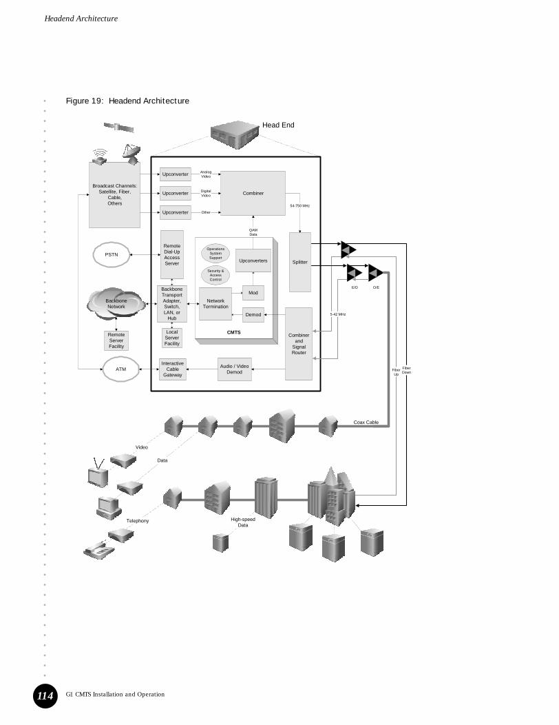
Headend Architecture
••••••••••••••••••••••••••••••••••••••••••••••••••••••••••
G1 CMTS Installation and Operation114
Figure 19: Headend Architecture
FiberUp
High-speedData
Telephony
Data
Video
Combinerand
SignalRouter
Audio / VideoDemod
BackboneTransportAdapter,Switch,LAN, or
Hub
LocalServerFacility
RemoteDial-UpAccessServer
InteractiveCable
Gateway
RemoteServerFacility
PSTN
Broadcast Channels:Satellite, Fiber,
Cable,Others
Upconverter
Upconverter
Upconverter
ATM
Splitter
AnalogVideo
DigitalVideo
Other
Combiner
54-750 MHz
5-42 MHz
BackboneNetwork
Head End
FiberDown
E/O O/E
Coax Cable
NetworkTermination
Demod
Mod
Upconverters
QAMData
OperationsSystemSupport
Security &AccessControl
CMTS
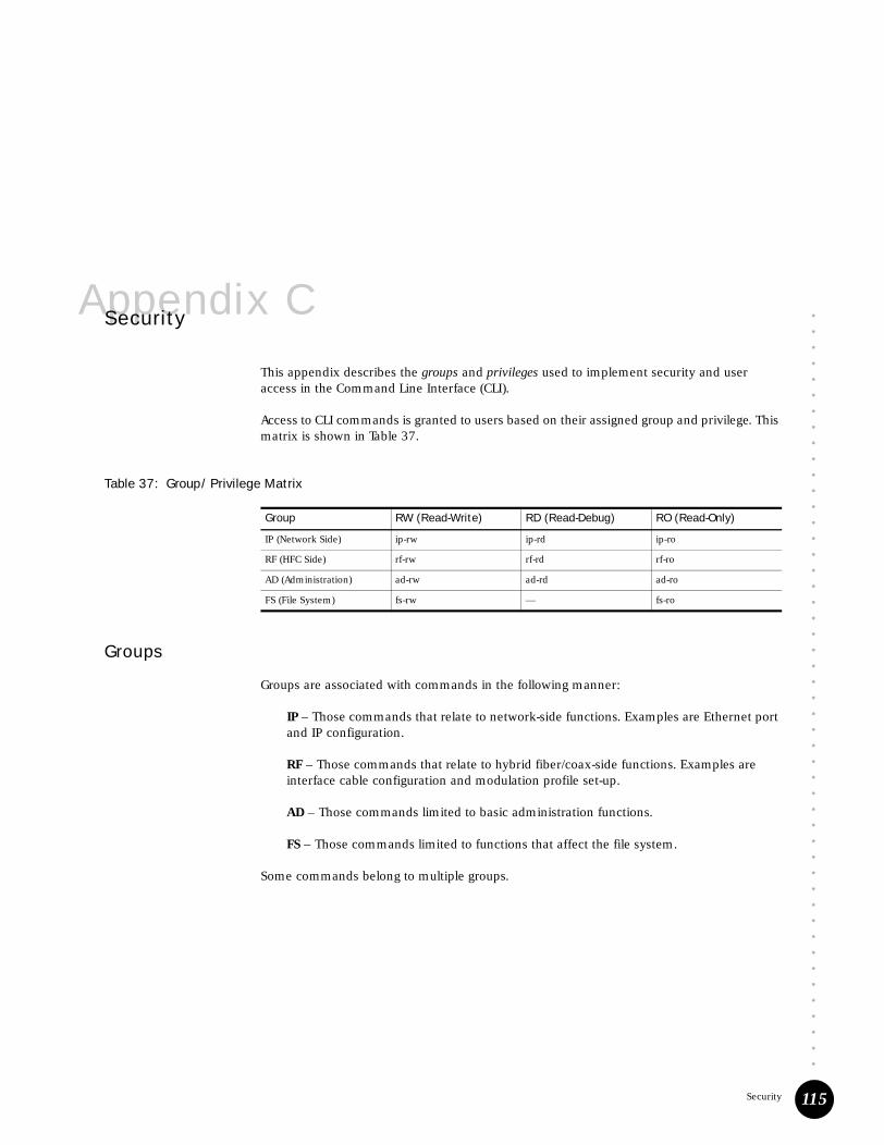
••••••••••••••••••••••••••••••••••••••••••••••••
Security 115
Appendix CSecurity
This appendix describes the groups and privileges used to implement security and user access in the Command Line Interface (CLI).
Access to CLI commands is granted to users based on their assigned group and privilege. This matrix is shown in Table 37.
Table 37: Group/Privilege Matrix
Groups
Groups are associated with commands in the following manner:
IP – Those commands that relate to network-side functions. Examples are Ethernet port and IP configuration.
RF – Those commands that relate to hybrid fiber/coax-side functions. Examples are interface cable configuration and modulation profile set-up.
AD – Those commands limited to basic administration functions.
FS – Those commands limited to functions that affect the file system.
Some commands belong to multiple groups.
Group RW (Read-Write) RD (Read-Debug) RO (Read-Only)
IP (Network Side) ip-rw ip-rd ip-ro
RF (HFC Side) rf-rw rf-rd rf-ro
AD (Administration) ad-rw ad-rd ad-ro
FS (File System) fs-rw — fs-ro

Security
••••••••••••••••••••••••••••••••••••••••••••••••••••••••••
G1 CMTS Installation and Operation116
Privileges
Each command in the CLI is associated with all the privileges that might be needed to operate that command as follows:
RW – Read-write allows a user to obtain a display from a command, and to input parameters to the command.
RD – Read-debug allows access to the series of debug commands. It also limits access to some of the show commands.
RO – Read-only allows a user to obtain a display from a command.
The three categories of privileges are hierarchical:
Commands
Each command in the CLI hierarchy of commands has one or more group-privileges associated with it. You cannot change this association. See “Commands Summary” of the G-series CMTS CLI Reference for associations, which are shown with abbreviations such as ip-ro, rf-rw and so forth.
Users
Each user can be assigned to multiple groups and privileges with the username command:
username <name> group {ad|ip|rf|fs} privilege {rw|ro|rd}
root is a username built in to the G1 CMTS that is assigned to all group-privileges.
A user that is not assigned to a group has access to a limited set of commands (see those commands that have a group of all in the “Commands Summary” of the G-series CMTS CLI Reference).
This Level Can Also Access This Level
RW RD, RO
RD RO
RO —

••••••••••••••••••••••••••••••••••••••••••••••••
G1 CMTS Local Log Events 117
Appendix DG1 CMTS Local Log Events
Table 38 lists the Juniper Networks-specific local log events for the G1 CMTS. The local event log of the CMTS corresponds to the docsDevEventTable within the DOCSIS Cable Device MIB (RFC-2669). See “Local Event Log” on page 89 for information on displaying the local log and controlling Juniper Networks-specific events and traps.
Following is an explanation of each column in Table 38:
! Event Class—events are categorized into Juniper Networks-specific event classes: ENVMON, CHASSIS, SOFTWARE, ACCESS, CONFIG, DATAPATH, RFINTERFACE, and FLAPLIST.
! Event Priority—corresponds to docsDevEvLevel in RFC-2669 and represents the priority level of the event. The priority levels, from most serious to least, are: emergency, alert, critical, error, warning, notice, information, and debug. See the DOCSIS OSSI specification for definitions of the standard DOCSIS CMTS events.
! Event Message—corresponds to docsDevEvText in RFC-2669 and provides a text description of the event. The event message contained in Table 38 is sometimes followed by additional text that provides more information regarding the event.
! Event ID—corresponds to docsDevEvId in RFC-2669, which is a unique 32-bit identifier (displayed as decimal) used by the G1 CMTS for the event.
! Trap Name—corresponds to the name of the trap that is generated (if enabled) when the event occurs.

G1 CMTS Local Log Events
••••••••••••••••••••••••••••••••••••••••••••••••••••••••••
G1 CMTS Installation and Operation118
Table 38: G1 CMTS Local Log Events
Event ClassEvent Priority Event Message Event ID Trap Name
ENVMON Emergency Thermal Shutdown 2539850101 Environment Monitoring Trap
ENVMON Emergency Firestop 2539850102 Environment Monitoring Trap
ENVMON Warning Single fan failure 2539850103 Environment Monitoring Trap
ENVMON Critical Multiple fan failure 2539850104 Environment Monitoring Trap
ENVMON Critical Power supply failed 2539850106 Environment Monitoring Trap
ENVMON Critical Ambient user high threshold reached, cannot rev up the fans
2539850108 Environment Monitoring Trap
ENVMON Inform Ambient user low threshold reached 2539850109 Environment Monitoring Trap
CHASSIS Inform Module inserted 2539850201 Chassis Trap
CHASSIS Inform Module removed 2539850202 Chassis Trap
CHASSIS Critical Module: unexpected shutdown or crash
2539850203 Chassis Trap
CHASSIS Inform Module went online 2539850204 Chassis Trap
CHASSIS Inform Module went offline 2539850205 Chassis Trap
CHASSIS Critical Module failed to start 2539850206 Chassis Trap
CHASSIS Error Interface/Channel failed to start 2539850207 Chassis Trap
SOFTWARE Inform Apply successful 2539850301 Software Trap
SOFTWARE Inform Commit successful 2539850302 Software Trap
SOFTWARE Notice Apply failed 2539850303 Software Trap
SOFTWARE Critical Install failed 2539850304 Software Trap
SOFTWARE Inform Install success 2539850305 Software Trap
SOFTWARE Inform Line card authorization successful 2539850306 Software Trap
SOFTWARE Notice Line card authorization unsuccessful 2539850307 Software Trap
SOFTWARE Warning Line card authorization option is corrupted
2539850308 Software Trap
SOFTWARE Critical Operational failure 2539850309 Software Trap
SOFTWARE Inform Apply cancelled 2539850310 Software Trap
ACCESS Inform CLI session begin 2539850401 Access Trap
ACCESS Inform CLI session end 2539850402 Access Trap
ACCESS Inform CLI session timeout 2539850403 Access Trap
ACCESS Warning CLI auth failure – superuser 2539850404 Access Trap
ACCESS Notice CLI auth failure – non-superuser 2539850405 Access Trap
CONFIG Inform Startup config changed 2539850501 Config Trap
CONFIG Inform DateTime changed 2539850502 Config Trap
CONFIG Warning Config Apply process had failure 2539850503 Config Trap
CONFIG Inform Startup file missing 2539850504 Config Trap
CONFIG Critical Corrupt startup file 2539850505 Config Trap
CONFIG Critical Persistent configuration file corrupted: <config-file-name>
2539850506 Config Trap
CONFIG Critical Version mismatch: non-recoverable 2539850507 Config Trap
CONFIG Inform Version mismatch: recoverable 2539850508 Config Trap

••••••••••••••••••••••••••••••••••••••••••••••••••••••••••
G1 CMTS Local Log Events 119
G1 CMTS Local Log Events
DATAPATH Inform Unverifiable IP address <ip-addr> received from CPE MAC <cpe-mac-addr>. CM MAC <cm-mac-addr>
2539850601 Datapath Trap
DATAPATH Inform Invalid IP address <ip-addr>, MAC address <cpe-mac-addr> received from CM MAC <cm-mac-addr>. The IP address is owned by MAC address <aat-mac-addr> behind CM MAC <aat-cm-mac-addr>
2539850602 Datapath Trap
DATAPATH Inform Invalid CPE IP <ip-addr>, MAC <cpe-mac-addr> from CM <cm-mac-addr>, address not allocated
2539850603 Datapath Trap
RFINTERFACE Warning US <slot>/<US nbr> changed from <XX.XX> MHz, <S1> ksymb/s, profile <P1> to <YY.YY> MHz, <S2> ksymb/s, profile <P2>
2539850701 RfInterface Trap
FLAPLIST Notice CM added to flaplist 2539850801 FlapList Trap
FLAPLIST Notice CM aged out from flaplist 2539850802 FlapList Trap
Event ClassEvent Priority Event Message Event ID Trap Name

G1 CMTS Local Log Events
••••••••••••••••••••••••••••••••••••••••••••••••••••••••••
G1 CMTS Installation and Operation120

••••••••••••••••••••••••••••••••••••••••••••••••
Radio Frequency (RF) Specifications 121
Appendix ERadio Frequency (RF) Specifications
For reference purposes, Table 39 through Table 43 are reproduced from the CableLabs DOCSIS Radio Frequency Interface Specification, SP-RFI-I05-991105. For the complete DOCSIS specifications, please see the appropriate CableLabs document.
Table 39: Downstream RF Channel Transmission Characteristics
Parameter Value
Frequency range Cable system normal downstream operating range is from 50 MHz to as high as 860 MHz. However, the values in this table apply only at frequencies >= 88 MHz.
RF channel spacing (design bandwidth) 6 MHz
Transit delay from headend to most distant customer <= 0.800 msec (typically much less)
Carrier-to-noise ratio in a 6-MHz band (analog video level) Not less than 35 dB4
Carrier-to-interference ratio for total power (discrete and broadband ingress signals)
Not less than 35 dB within the design bandwidth
Composite triple beat distortion for analog modulated carriers Not greater than -50 dBc within the design bandwidth
Composite second order distortion for analog odulated carriers Not greater than -50 dBc within the design bandwidth
Cross-modulation level Not greater than -40 dBc within the design bandwidth
Amplitude ripple 0.5 dB within the design bandwidth
Group delay ripple in the spectrum occupied by the CMTS 75 ns within the design bandwidth
Micro-reflections bound for dominant echo -10 dBc @ <= 0.5 m sec, -15 dBc @ <= 1.0 m sec-20 dBc @ <= 1.5 m sec, -30 dBc @ > 1.5 m sec
Carrier hum modulation Not greater than -26 dBc (5%)
Burst noise Not longer than 25 m sec at a 10 Hz average rate
Seasonal and diurnal signal level variation 8 dB
Signal level slope, 50-750 MHz 16 dB
Maximum analog video carrier level at the CM input, inclusive of above signal level variation
17 dBmV
Lowest analog video carrier level at the CM input, inclusive of above signal level variation
-5 dBmV
1. Transmission is from the headend combiner to the CM input at the customer location.2. For measurements above the normal downstream operating frequency band (except hum), impairments are referenced to the
highest-frequency NTSC carrier level.3. For hum measurements above the normal downstream operating frequency band, a continuous-wave carrier is sent at the test frequency
at the same level as the highest-frequency NTSC carrier.4. This presumes that the digital carrier is operated at analog peak carrier level. When the digital carrier is operated below the analog peak
carrier level, this C/N may be less.5. Measurement methods defined in [NCTA] or [CableLabs2].

Radio Frequency (RF) Specifications
••••••••••••••••••••••••••••••••••••••••••••••••••••••••••
G1 CMTS Installation and Operation122
Table 40: Upstream RF Channel Transmission Characteristics
Table 41: Downstream RF Signal Output Characteristics
Parameter Value
Frequency range 5 to 42 MHz edge to edge
Transit delay from the most distant CM to the nearest
CM or CMTS
<= 0.800 msec (typically much less)
Carrier-to-noise ratio Not less than 25 dB
Carrier-to-ingress power (the sum of discrete and
broadband ingress signals) ratio
Not less than 25 dB2
Carrier- to-interference (the sum of noise, distortion, common-path distortion and cross-modulation) ratio
Not less than 25 dB
Carrier hum modulation Not greater than -23 dBc (7.0%)
Burst noise Not longer than 10 msec at a 1 kHz average rate for most cases3,4,5
Amplitude ripple 5-42 MHz: 0.5 dB/MHz
Group delay ripple 5-42 MHz: 200 ns/MHz
Micro-reflections -- single echo -10 dBc @ <= 0.5 m sec-20 dBc @ <= 1.0 m sec-30 dBc @ > 1.0 m sec
Seasonal and diurnal signal level variation Not greater than 8 dB min to max
1. Transmission is from the CM output at the customer location to the headend.2. Ingress avoidance or tolerance techniques MAY be used to ensure operation in the presence of time-varying discrete ingress signals that
could be as high as 0 dBc [CableLabs1].3. Amplitude and frequency characteristics sufficiently strong to partially or wholly mask the data carrier.4. CableLabs report containing distribution of return-path burst noise measurements and measurement method is forthcoming.5. Impulse noise levels more prevalent at lower frequencies (< 15 MHz).
Parameter Value
Center Frequency (fc) 91 to 857 MHz ± 30 kHz1
Level Adjustable over the range 50 to 61 dBmV
Symbol Rate (nominal)64QAM256QAM
5.056941 Msym/sec5.360537 Msym/sec
Nominal Channel Spacing 6 MHz
Frequency response64QAM256QAM
~18% Square Root Raised Cosine shaping~12% Square Root Raised Cosine shaping

••••••••••••••••••••••••••••••••••••••••••••••••••••••••••
Radio Frequency (RF) Specifications 123
Radio Frequency (RF) Specifications
Table 42: DOCSIS Downstream Channel Rates and Spacing
Table 43: DOCSIS Maximum Upstream Channel Rates and Widths
Total Discrete Spurious Inband (fc ± 3 MHz)
Inband Spurious and Noise (fc ± 3 MHz)
Adjacent channel (fc ± 3.0 MHz) to (fc ± 3.75 MHz)
Adjacent channel (fc ± 3.75 MHz) to (fc ± 9 MHz)
Next adjacent channel (fc ± 9 MHz) to (fc ± 15 MHz)
Other channels (47 MHz to 1,000 MHz)
< -57dBc
< -48dBc; where channel spurious and noise includes all discrete spurious, noise, carrier leakage, clock lines, synthesizer products, and other undesired transmitter products. Noise within +/- 50kHz of the carrier is excluded.
< -58 dBc in 750 kHz
< -62 dBc, in 5.25 MHz, excluding up to 3 spurs, each of which must be <-60 dBc when measured in a 10 kHz band
Less than the greater of -65 dBc or -12dBmV in 6MHz, excluding up to three discrete spurs. The total power in the spurs must be < -60dBc when each is measured with 10 kHz bandwidth.
< -12dBmV in each 6 MHz channel, excluding up to three discrete spurs. The total power in the spurs must be < -60dBc when each is measured with 10kHz bandwidth.
Phase Noise 1 kHz - 10 kHz: -33dBc double sided noise power
10 kHz - 50 kHz: -51dBc double sided noise power
50 kHz - 3 MHz: -51dBc double sided noise power
Output Impedance 75 ohms
Output Return Loss > 14 dB within an output channel up to 750 MHz; > 13 dB in an output channel above 750 MHz
Connector F connector per [IPS-SP-406]
1. ±30 kHz includes an allowance of 25 kHz for the largest FCC frequency offset normally built into upconverters.
Nominal Symbol Rate(Msym/sec)
Nominal Channel Spacing(kHz) Bit Rate (bps)
5.056941 (64QAM) 6000 30,341,646
5.360537 (256QAM) 6000 42,884,296
Symbol Rate(ksym/sec)
Channel Width(kHz)1
Bit-rate/sec(QPSK)
Bit-rate/sec(16QAM)
160 200 320,000 640,000
320 400 640,000 1,280,000
640 800 1,280,000 2,560,000
1,280 1,600 2,560,000 5,120,000
2,560 3,200 5,120,000 10,240,000
1. Channel width is the -30 dB bandwidth.
Parameter Value

Radio Frequency (RF) Specifications
••••••••••••••••••••••••••••••••••••••••••••••••••••••••••
G1 CMTS Installation and Operation124

••••••••••••••••••••••••••••••••••••••••••••••••
Coaxial Cable Requirements 125
Appendix FCoaxial Cable Requirements
To achieve optimal RF performance, and to minimize the potential damage of the F-connectors on the G1 CMTS, Juniper Networks recommends that the coaxial cable types listed in Table 44 be used.
Table 44: Coaxial Cable Requirements
Any of the cable types listed in Table 44 can be used initially. However, if a cable in a particular F-connector is replaced, we recommend that the replacement cable have the same, or larger, center conductor diameter than the original cable. This ensures that proper contact between the cable conductor and an F-connector will be maintained.
If a replacement cable has a smaller center conductor diameter than the original cable—for example, replacing an RG-6 cable with an RG-59U—the smaller RG-59U cable conductor might not make adequate contact with an F-connector, which can potentially lead to a partial or complete loss of the signal.
Cable Type Diameter of Center Conductor
RG-59/U 0.57 mm (0.022 in)
RG-59 0.86 mm (0.034 in)
RG-6 1.05 mm (0.041 in)

Coaxial Cable Requirements
••••••••••••••••••••••••••••••••••••••••••••••••••••••••••
G1 CMTS Installation and Operation126

••••••••••••••••••••••••••••••••••••••••••••••••
EIA Channel Plans 127
Appendix GEIA Channel Plans
Table 45 lists the EIA (Electronic Industries Association) standard, IRC (Incrementally Related Carrier), and HRC (Harmonically Related Carrier) frequency plans.
The frequencies in Table 45 represent the video center frequencies. Add 1.75 MHz to calculate the DOCSIS center frequency.
Table 45: EIA Channel Plan
Channel STD IRC HRC
T-7 7.0000
T-8 13.0000
T-9 19.0000
T-10 25.0000
T-11 31.0000
T-12 37.0000
T-13 43.0000
1 / A-8 73.2625 72.0036
2 55.2500 55.2625 54.0027
3 61.2500 61.2625 60.0030
4 67.2500 67.2625 66.0033
5 / A-7 77.2500 79.2625 78.0039
6 / A-6 83.2500 85.2625 84.0042
7 175.2500 175.2625 174.0087
8 181.2500 181.2625 180.0090
9 187.2500 187.2625 186.0093
10 193.2500 193.2625 192.0096
11 199.2500 199.2625 198.0099
12 205.2500 205.2625 204.0102
13 211.2500 211.2625 210.0105
14 / A 121.2625 121.2625 120.0060
15 / B 127.2625 127.2625 126.0063
16 / C 133.2625 133.2625 132.0066
17 / D 139.2500 139.2625 138.0069
18 / E 145.2500 145.2625 144.0072
19 / F 151.2500 151.2625 150.0075

EIA Channel Plans
••••••••••••••••••••••••••••••••••••••••••••••••••••••••••
G1 CMTS Installation and Operation128
20 / G 157.2500 157.2625 156.0078
21 / H 163.2500 163.2625 162.0081
22 / I 169.2500 169.2625 168.0084
23 / J 217.2500 217.2625 216.0108
24 / K 223.2500 223.2625 222.0111
25 / L 229.2625 229.2625 228.0114
26 / M 235.2625 235.2625 234.0117
27 / N 241.2625 241.2625 240.0120
28 / O 247.2625 247.2625 246.0123
29 / P 253.2625 253.2625 252.0126
30 / Q 259.2625 259.2625 258.0129
31 / R 265.2625 265.2625 264.0132
32 / S 271.2625 271.2625 270.0135
33 / T 277.2625 277.2625 276.0138
34 / U 283.2625 283.2625 282.0141
35 / V 289.2625 289.2625 288.0144
36 / W 295.2625 295.2625 294.0147
37 / AA 301.2625 301.2625 300.0150
38 / BB 307.2625 307.2625 306.0153
39 / CC 313.2625 313.2625 312.0156
40 / DD 319.2625 319.2625 318.0159
41 / EE 325.2625 325.2625 324.0162
42 / FF 331.2750 331.2750 330.0165
43 / GG 337.2625 337.2625 336.0168
44 / HH 343.2625 343.2625 342.0171
45 / II 349.2625 349.2625 348.0174
46 / JJ 355.2625 355.2625 354.0177
47 / KK 361.2625 361.2625 360.0180
48 / LL 367.2625 367.2625 366.0183
49 / MM 373.2625 373.2625 372.0186
50 / NN 379.2625 379.2625 378.0189
51 / OO 385.2625 385.2625 384.0192
52 / PP 391.2625 391.2625 390.0195
53 / QQ 397.2625 397.2625 396.0198
54 / RR 403.2500 403.2625 402.0201
55 / SS 409.2500 409.2625 408.0204
56 / TT 415.2500 415.2625 414.0207
57 / UU 421.2500 421.2625 420.0210
58 / VV 427.2500 427.2625 426.0213
59 / WW 433.2500 433.2625 432.0216
60 / XX 439.2500 439.2625 438.0219
61 / YY 445.2500 445.2625 444.0222
62 / ZZ 451.2500 451.2625 450.0225
Channel STD IRC HRC

••••••••••••••••••••••••••••••••••••••••••••••••••••••••••
EIA Channel Plans 129
EIA Channel Plans
63 / AAA 457.2500 457.2625 456.0228
64 / BBB 463.2500 463.2625 462.0231
65 / CCC 469.2500 469.2625 468.0234
66 / DDD 475.2500 475.2625 474.0237
67 / EEE 481.2500 481.2625 480.0240
68 / FFF 487.2500 487.2625 486.0243
69 / GGG 493.2500 493.2625 492.0246
70 / HHH 499.2500 499.2625 498.0249
71 / III 505.2500 505.2625 504.0252
72 / JJJ 511.2500 511.2625 510.0255
73 / KKK 517.2500 517.2625 516.0258
74 / LLL 523.2500 523.2625 522.0261
75 / MMM 529.2500 529.2625 528.0264
76 / NNN 535.2500 535.2625 534.0267
77 / OOO 541.2500 541.2625 540.0270
78 / PPP 547.2500 547.2625 546.0273
79 / QQQ 553.2500 553.2625 552.0276
80 / RRR 559.2500 559.2625 558.0279
81 / SSS 565.2500 565.2625 564.0282
82 / TTT 571.2500 571.2625 570.0285
83 / UUU 577.2500 577.2625 576.0288
84 / VVV 583.2500 583.2625 582.0291
85 / WWW 589.2500 589.2625 588.0294
86 / XXX 595.2500 595.2625 594.0297
87 / YYY 601.2500 601.2625 600.0300
88 / ZZZ 607.2500 607.2625 606.0303
89 613.2500 613.2625 612.0306
90 619.2500 619.2625 618.0309
91 625.2500 625.2625 624.0312
92 631.2500 631.2625 630.0315
93 637.2500 637.2625 636.0318
94 643.2500 643.2625 642.0321
95 / A-5 91.2500 91.2625 90.0045
96 / A-4 97.2500 97.2625 96.0048
97 / A-3 103.2500 103.2625 102.0051
98 / A-2 109.2750 109.2750 108.0054
99 / A-1 115.2750 115.2750 114.0057
100 649.2500 649.2625 648.0324
101 655.2500 655.2625 654.0327
102 661.2500 661.2625 660.0330
103 667.2500 667.2625 666.0333
104 673.2500 673.2625 672.0336
105 679.2500 679.2625 678.0339
Channel STD IRC HRC

EIA Channel Plans
••••••••••••••••••••••••••••••••••••••••••••••••••••••••••
G1 CMTS Installation and Operation130
106 685.2500 685.2625 684.0342
107 691.2500 691.2625 690.0345
108 697.2500 697.2625 696.0348
109 703.2500 703.2625 702.0351
110 709.2500 709.2625 708.0354
111 715.2500 715.2625 714.0357
112 721.2500 721.2625 720.0360
113 727.2500 727.2625 726.0363
114 733.2500 733.2625 732.0366
115 739.2500 739.2625 738.0369
116 745.2500 745.2625 744.0372
117 751.2500 751.2625 750.0375
118 757.2500 757.2625 756.0378
119 763.2500 763.2625 762.0381
120 769.2500 769.2625 768.0384
121 775.2500 775.2625 774.0387
122 781.2500 781.2625 780.0390
123 787.2500 787.2625 786.0393
124 793.2500 793.2625 792.0396
125 799.2500 799.2625 798.0399
126 805.2500 805.2625 804.0402
127 811.2500 811.2625 810.0405
128 817.2500 817.2625 816.0408
129 823.2500 823.2625 822.0411
130 829.2500 829.2625 828.0414
131 835.2500 835.2625 834.0417
132 841.2500 841.2625 840.0420
133 847.2500 847.2625 846.0423
134 853.2500 853.2625 852.0426
135 859.2500 859.2625 858.0429
136 865.2500 865.2625 864.0432
137 871.2500 871.2625 870.0435
138 877.2500 877.2625 876.0438
139 883.2500 883.2625 882.0441
140 889.2500 889.2625 888.0444
141 895.2500 895.2625 894.0447
142 901.2500 901.2625 900.0450
143 907.2500 907.2625 906.0453
144 913.2500 913.2625 912.0456
145 919.2500 919.2625 918.0459
146 925.2500 925.2625 924.0462
147 931.2500 931.2625 930.0465
148 937.2500 937.2625 936.0468
Channel STD IRC HRC

••••••••••••••••••••••••••••••••••••••••••••••••••••••••••
EIA Channel Plans 131
EIA Channel Plans
149 943.2500 943.2625 942.0471
150 949.2500 949.2625 948.0474
151 955.2500 955.2625 954.0477
152 961.2500 961.2625 960.0480
153 967.2500 967.2625 966.0483
154 973.2500 973.2625 972.0486
155 979.2500 979.2625 978.0489
156 985.2500 985.2625 984.0492
157 991.2500 991.2625 990.0495
158 997.2500 997.2625 996.0498
159 1003.250 1003.2625 1002.0501
Channel STD IRC HRC

EIA Channel Plans
••••••••••••••••••••••••••••••••••••••••••••••••••••••••••
G1 CMTS Installation and Operation132

••••••••••••••••••••••••••••••••••••••••••••••••
133
Part 4Index
! Index on page 135

••••••••••••••••••••••••••••••••••••••••••••••••••••••••••
G1 CMTS Installation and Operation134

••••••••••••••••••••••••••••••••••••••••••••••••
Index 135
IndexIndex
Numerics10/100BASE ................................................................3216QAM..................................................................52, 53256QAM....................................................................10264QAM..............................................................102, 103
Aaccessory kit................................................................27agency certifications..................................................111air intake .................................................................9, 30amplification ...............................................................87attenuation ..........................................................87, 102authentication .............................................................97autosensing .................................................................35
Bbandwidth ...................................................................98banner.........................................................................50Bits per second............................................................39Broadband Cable Processor ASIC ..................................5
Ccablecoaxial....................................................32, 33, 125plant.....................................................................33
cable interface .............................................................41CATV mode .................................................................75CCCM ........................................................................102CER .............................................................................94certifications..............................................................111channel ...................................................................4, 32
downstream.................................................96, 102upstream................................................94, 96, 100width....................................................................45
chassis...............................................................6, 30, 35ground nuts......................................................9, 31grounding.............................................................12lifting....................................................................11mounting .............................................................30
Chassis Control Module .................................5, 9, 34, 39
Class of Service............................................................98CLI see Command Line Interfaceclock............................................................................49codeword ..................................................................103Codeword Error Ratio..................................................94Command Line Interface .............................................40common path distortion ..............................................87community string ........................................................69concatenation................................................................5configuration ...............................................................40configuration file .........................................................98
invalid ..................................................................98issues .............................................................87, 98modified...............................................................97name....................................................................97receiving...............................................................97
congestion .................................................................101correction factor ..........................................................78counter
CER ........................................................86, 89, 103IM.............................................................86, 96, 98MER .....................................................................86P-Adj ....................................................................89PAdj .....................................................................86SM................................................................86, 102SNR ......................................................................86Total .....................................................................86
CPE......................................................................64, 102
Ddata backoff.................................................................46Data bits ......................................................................39date .............................................................................49DB-25 ..........................................................................34DB-9 ............................................................................34debug ..........................................................................83decryption .....................................................................5DHCP.........................................................64, 87, 91, 97directory......................................................................70
changing...............................................................70displaying.............................................................70
DNS .............................................................................70

••••••••••••••••••••••••••••••••••••••••••••••••••••••••••
Index
G1 CMTS Installation and Operation136
DOCSISRFI Specifications...............................................121
DOCSIS Module........................................... 5, 9, 33, 101document conventions............................................... xivDomain Name Server.................................................. 70downstream.............................................. 32, 33, 44, 45
Eencryption.....................................................................5equalization............................................................... 101equipment shelf .......................................................... 30Ethernet ...................................................................... 32
Ffan ................................................................................9Fast Ethernet............................................................... 46F-connector ................................................... 32, 33, 125FEC .............................................................................52fiberoptic link .............................................................. 88flap-list ................................................................ 83, 102flow control ................................................................. 39forward error correction.............................................. 52forward path ....................................................... 88, 101fragmentation ...............................................................5FTP ...........................................................................106
GG1 CMTSfunctional overview................................................3management..........................................................6
GIADDR.......................................................................64ground ........................................................................ 12group delay variance ................................................... 88guard time................................................................... 52
Hheadend ..................................................................3, 94help.............................................................................48HFC network .................................................................4hostname .................................................................... 49
I IEC .............................................................................. 35impairment identification........................................6, 94ingress....................................................... 6, 87, 94, 103initial maintenance...................................................... 54interface...................................................................... 41interleave depth .......................................................... 44interleaver................................................................. 103
Interval Usage Code.....................................................51IP address....................................................................97IP connectivity.............................................................97
Llaser clipping .........................................................87, 89LED
power supply .......................................................38LEDs..............................................................................9load balancing ...........................................................100logout ..........................................................................40long data grant interval ...............................................54
MMAC ..........................................................................102address ..........................................................83, 90domain...........................................................41, 96messages .............................................................90
major components ........................................................5MAP ....................................................................90, 102maxburst size..............................................................52Media Gateways ............................................................4MER ............................................................................94Message Integrity Check..............................................97MIC see Message Integrity Checkmicroreflections ......................................................6, 94minislot size ................................................................46modulation............................................................44, 52modulation profile.............................51, 53, 53–54, 101mounting bracket ....................................................9, 30multicast packets.........................................................55
Nnetwork side interface ...................................................4NMS ............................................................................96node......................................................................32, 33
recombining.......................................................100noise ...................................................6, 52, 87, 94, 103
cancellation........................................................101power...................................................................94power density ......................................................94
NSI ............................................................................102
Pparity...........................................................................39password...............................................................43, 48PC .........................................................................34, 39periodic ranging ........................................................102phase distortion...........................................................88ping.............................................................................71

••••••••••••••••••••••••••••••••••••••••••••••••••••••••••
Index 137
Index
port ...........................................................................100DB-25...................................................................34DB-9.....................................................................34downstream...................................................32, 33Ethernet ...............................................................32F-connector ............................................32, 33, 125RS-232 .................................................................34serial ..............................................................34, 39upstream..............................................................33
poweradjustment .....................................................83, 89cord................................................................11, 35issues ...................................................................95level .............................................................46, 102redundancy ..........................................................35source ......................................................35, 37, 95supply ..............................................................9, 96
power receptacleAC ....................................................................9, 35
preamble .....................................................................52privilege ......................................................................48provisioning ......................................55, 83, 88, 97, 100
QQoS .............................................................................98QPSK.......................................................52, 53, 88, 101
Rrack mount..................................................................11range.............................................................83, 96, 102range backoff ..............................................................46registration ..................................................................88request interval ...........................................................54return path ......................................88, 94, 96, 100, 102RF power.....................................................................44RG-59 ........................................................................125RG-59/U.....................................................................125RG-6 ..........................................................................125running-config file .................................................43, 71
Sscrambler ....................................................................52ServiceGuard Management System .......................75, 94shared secret .........................................................69, 97shipping carton .....................................................27, 29short data grant interval ..............................................54shortened last codeword .............................................52siaddr field ..................................................................97SID ..............................................................................90signal amplitude ..........................................................88SNMP ..........................................................................96SNR .......................................................................83, 94spectrum analyzer ...........................................75, 76, 77
spectrum monitoring...................................................94startup-config file...................................................43, 71station maintenance ......................................54, 83, 102Stop bits ......................................................................39
Ttemperature...........................................................87, 96terminal emulation ......................................................39terminal guard
DC..........................................................................9TFTP......................................................................87, 97throughput.................................................................103TLV..............................................................................55TOD.............................................................................98traceroute ....................................................................71
Uupstream .............................................32, 33, 45, 46, 99upstream channel width ............................................100upstream modulation profile .......................................51username ..............................................................43, 48
Vvideo servers .................................................................4Virtual Private Network................................................55VPN see Virtual Private NetworkVSIF.............................................................................55

••••••••••••••••••••••••••••••••••••••••••••••••••••••••••
Index
G1 CMTS Installation and Operation138