“jupiter” global positioning system (gps) receiver · pdf filedata sheet january...
TRANSCRIPT
Data Sheet January 19, 1998 Order No. GD003E
“Jupiter” Global Positioning System (GPS) Receiver(Part No. TU30-D140-221/231)
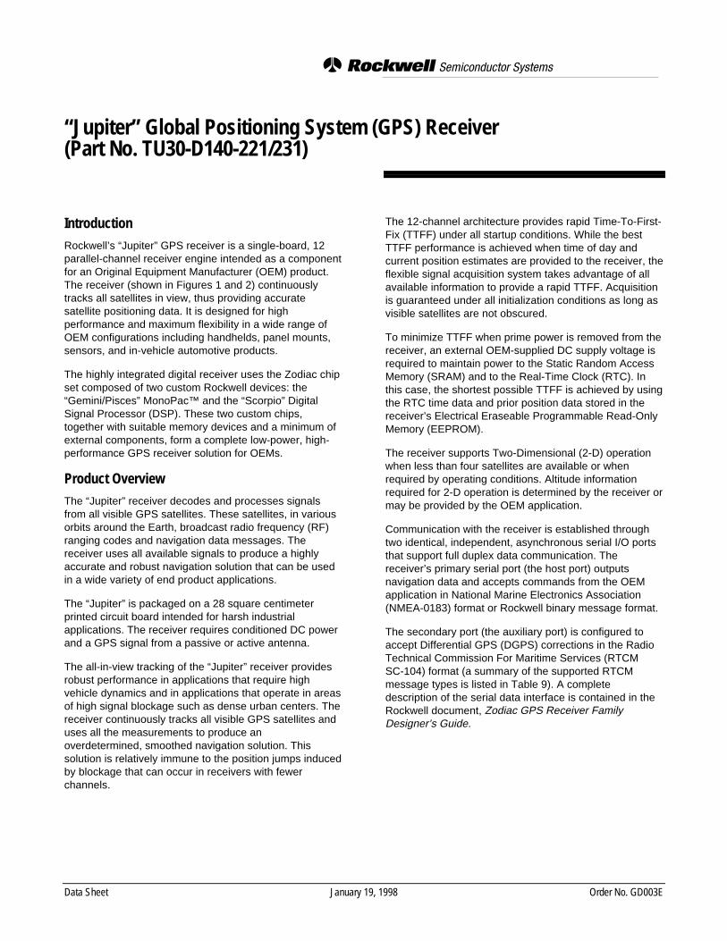
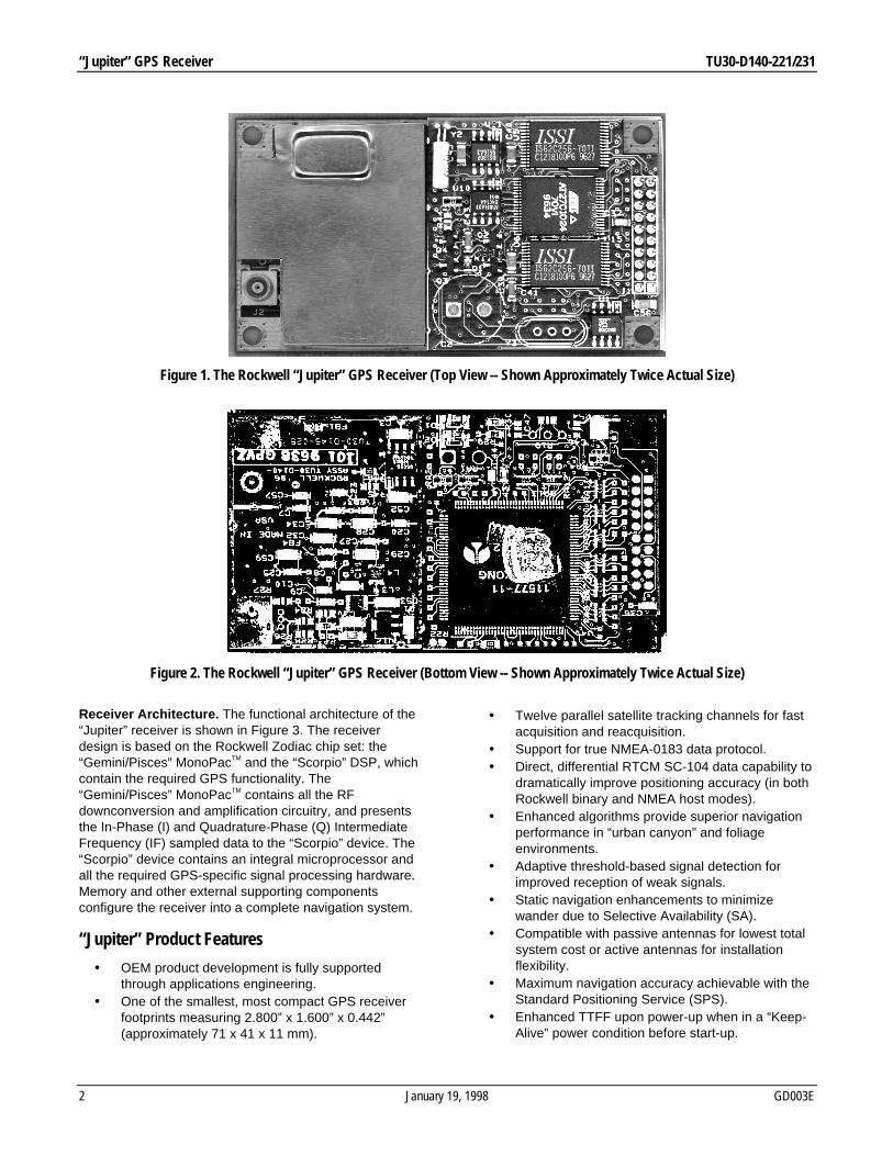
IntroductionRockwell’s “Jupiter” GPS receiver is a single-board, 12parallel-channel receiver engine intended as a componentfor an Original Equipment Manufacturer (OEM) product.The receiver (shown in Figures 1 and 2) continuouslytracks all satellites in view, thus providing accuratesatellite positioning data. It is designed for highperformance and maximum flexibility in a wide range ofOEM configurations including handhelds, panel mounts,sensors, and in-vehicle automotive products.
The highly integrated digital receiver uses the Zodiac chipset composed of two custom Rockwell devices: the“Gemini/Pisces” MonoPac™ and the “Scorpio” DigitalSignal Processor (DSP). These two custom chips,together with suitable memory devices and a minimum ofexternal components, form a complete low-power, high-performance GPS receiver solution for OEMs.
Product OverviewThe “Jupiter” receiver decodes and processes signalsfrom all visible GPS satellites. These satellites, in variousorbits around the Earth, broadcast radio frequency (RF)ranging codes and navigation data messages. Thereceiver uses all available signals to produce a highlyaccurate and robust navigation solution that can be usedin a wide variety of end product applications.
The “Jupiter” is packaged on a 28 square centimeterprinted circuit board intended for harsh industrialapplications. The receiver requires conditioned DC powerand a GPS signal from a passive or active antenna.
The all-in-view tracking of the “Jupiter” receiver providesrobust performance in applications that require highvehicle dynamics and in applications that operate in areasof high signal blockage such as dense urban centers. Thereceiver continuously tracks all visible GPS satellites anduses all the measurements to produce anoverdetermined, smoothed navigation solution. Thissolution is relatively immune to the position jumps inducedby blockage that can occur in receivers with fewerchannels.
The 12-channel architecture provides rapid Time-To-First-Fix (TTFF) under all startup conditions. While the bestTTFF performance is achieved when time of day andcurrent position estimates are provided to the receiver, theflexible signal acquisition system takes advantage of allavailable information to provide a rapid TTFF. Acquisitionis guaranteed under all initialization conditions as long asvisible satellites are not obscured.
To minimize TTFF when prime power is removed from thereceiver, an external OEM-supplied DC supply voltage isrequired to maintain power to the Static Random AccessMemory (SRAM) and to the Real-Time Clock (RTC). Inthis case, the shortest possible TTFF is achieved by usingthe RTC time data and prior position data stored in thereceiver’s Electrical Eraseable Programmable Read-OnlyMemory (EEPROM).
The receiver supports Two-Dimensional (2-D) operationwhen less than four satellites are available or whenrequired by operating conditions. Altitude informationrequired for 2-D operation is determined by the receiver ormay be provided by the OEM application.
Communication with the receiver is established throughtwo identical, independent, asynchronous serial I/O portsthat support full duplex data communication. Thereceiver’s primary serial port (the host port) outputsnavigation data and accepts commands from the OEMapplication in National Marine Electronics Association(NMEA-0183) format or Rockwell binary message format.
The secondary port (the auxiliary port) is configured toaccept Differential GPS (DGPS) corrections in the RadioTechnical Commission For Maritime Services (RTCMSC-104) format (a summary of the supported RTCMmessage types is listed in Table 9). A completedescription of the serial data interface is contained in theRockwell document, Zodiac GPS Receiver FamilyDesigner’s Guide.
“Jupiter” GPS Receiver TU30-D140-221/231
2 January 19, 1998 GD003E
Receiver Architecture. The functional architecture of the“Jupiter” receiver is shown in Figure 3. The receiverdesign is based on the Rockwell Zodiac chip set: the“Gemini/Pisces” MonoPacTM and the “Scorpio” DSP, whichcontain the required GPS functionality. The“Gemini/Pisces” MonoPacTM contains all the RFdownconversion and amplification circuitry, and presentsthe In-Phase (I) and Quadrature-Phase (Q) IntermediateFrequency (IF) sampled data to the “Scorpio” device. The“Scorpio” device contains an integral microprocessor andall the required GPS-specific signal processing hardware.Memory and other external supporting componentsconfigure the receiver into a complete navigation system.
“Jupiter” Product Features
• OEM product development is fully supportedthrough applications engineering.
• One of the smallest, most compact GPS receiverfootprints measuring 2.800” x 1.600” x 0.442”(approximately 71 x 41 x 11 mm).
• Twelve parallel satellite tracking channels for fastacquisition and reacquisition.
• Support for true NMEA-0183 data protocol.• Direct, differential RTCM SC-104 data capability to
dramatically improve positioning accuracy (in bothRockwell binary and NMEA host modes).
• Enhanced algorithms provide superior navigationperformance in “urban canyon” and foliageenvironments.
• Adaptive threshold-based signal detection forimproved reception of weak signals.
• Static navigation enhancements to minimizewander due to Selective Availability (SA).
• Compatible with passive antennas for lowest totalsystem cost or active antennas for installationflexibility.
• Maximum navigation accuracy achievable with theStandard Positioning Service (SPS).
• Enhanced TTFF upon power-up when in a “Keep-Alive” power condition before start-up.
Figure 2. The Rockwell “Jupiter” GPS Receiver (Bottom View -- Shown Approximately Twice Actual Size)
Figure 1. The Rockwell “Jupiter” GPS Receiver (Top View -- Shown Approximately Twice Actual Size)

TU30-D140-221/231 “Jupiter” GPS Receiver
GD003E January 19, 1998 3
• Meets rigid shock and vibration requirements.• Automatic Altitude Hold Mode from Three-
Dimensional to Two-Dimensional navigation.• Automatic cold start acquisition process (when no
initialization data is entered by the user).• Maximum operational flexibility and configurability
via user commands over the host serial port.• Ability to accept externally supplied initialization
data over the host serial port.• User selectable satellites.• User selectable visible satellite mask angle.• Standard straight OSX subminiature, snap-on,
coaxial RF jack receptacle.• Standard 2x10 pin-field I/O connector.• Operation/storage over an extended temperature
range (-40° C to +85° C).
Product ApplicationsThe “Jupiter” GPS receiver is suitable for a wide range ofOEM highly integrated GPS design applications such as:
• Handheld GPS receiver applications.• Automotive applications.• Marine navigation applications.• Aviation applications.• Timing applications.
Figure 4 illustrates an architecture that might be used tointegrate the receiver with an applications processor thatdrives peripheral devices such as a display and keyboard.The interface between the applications processor and thereceiver is through the serial data interface.
Ordering InformationTo order the receiver, use Rockwell part number TU30-D140-221/231. For the complete part number, pricing, anddelivery information, contact any one of the RockwellRegional Sales Offices shown on the last page of thisData Sheet.
Technical DescriptionGeneral Information . The “Jupiter” GPS receiver requires+5 volts primary DC input power. The receiver canoperate from either an active or passive GPS antenna,supplied by the OEM, to receive L1 band frequency GPScarrier signals.
Since the receiver determines its position by rangingsignals from four or more GPS satellites orbiting the Earth,its antenna must have reasonable visibility of the sky. Thisis generally not a problem when the receiver is usedoutdoors in the open. However, when used indoors orinside of an automobile, the antenna should be positionedin such a way as to have an unobstructed “view” of thesky. To establish an initial navigation fix, the receiver
Pre-Select Filter
RF Connector
Post-Select Filter
RF MONOPAC
"PISCES"
SIGNAL SAMPLES
Serial Port 2
Serial Port 1
Timing Reference
OEM Host Interface
1PPS, 10 KHz
CLKS
AAMP2-8
SRAM
Serial EEPROM
ROM** contains Rockwell software
RTC
DGPS Data (RTCM SC-104)
"SCORPIO" DSP
A/D CTRL
"GEMINI"
Power Supervisor and SRAM Control
Logic
EMI Filtering, Voltage Regulator,
Backup Source
10.95 MHz XTAL
29 MHz XTAL
32 KHz XTAL
DC Regulated Power
RESET
RESET_FBackup Power
+5 VDC Prime Power
RW203
Figure 3. “Jupiter” Receiver Architecture

“Jupiter” GPS Receiver TU30-D140-221/231
4 January 19, 1998 GD003E
requires a minimum of four satellites in track with goodgeometry (Geometric Dilution of Precision [GDOP]<10).
If satellite signals are blocked, the length of time for thereceiver to receive those signals and determine itsposition will be longer. If fewer than four satellites arebeing tracked, or if the satellite geometry is degraded,signal blockage may result in a failure to navigate.
Satellite Acquisition . The “Jupiter” GPS receiversupports four types of satellite signal acquisitiondepending on the availability of critical data. Table 1provides the corresponding TTFF times for each of thefollowing acquisition states.
• Warm Start . A warm start results from a softwarereset after a period of continuous navigation or areturn from a short idle period (i.e., a few minutes)that was preceded by a period of continuousnavigation. In this state, all of the critical data(position, velocity, time, and satellite ephemeris) is
valid to the specified accuracy and available inSRAM.
• Initialized Start . An initialized start typically resultsfrom user-supplied position and time initializationdata or continuous RTC operation with an accuratelast known position available from EEPROM. Inthis state, position and time data are present andvalid but ephemeris data validity has expired.
• Cold Start . A cold start acquisition state resultswhen position and/or time data is unknown, eitherof which results in an unreliable satellite visibilitylist. Almanac information is used to identifypreviously healthy satellites.
• Frozen Start . A frozen start acquisition stateoccurs if there are no valid internal data sourcesavailable.
Figure 4. Typical “Jupiter”/OEM Architecture
GPS Receiver Engine
OEM Applications Processor
Display
Keypad
Power/Communications Interface
Preamplifier (Optional)
Power Supply
DGPS (Optional)
RW101
GPS Antenna
Table 1. “Jupiter” Receiver Signal Acquisition
Time-To-First-Fix Initial Error Uncertainties (3 Sigma)MaximumAlmanac
Age
MaximumEphemeris
AgeSatellite
AcquisitionState
Typical(minutes)
90% Probable(minutes)
Position (km) Velocity(m/sec)
Time(minutes)
Weeks Hours
WarmInitialized
ColdFrozen
0.300.82.0(*)
0.41.02.5(*)
100100N/AN/A
7575
N/AN/A
55
N/AN/A
111
N/A
4N/AN/AN/A
N/A = Not available in real-time to the receiver. Note that times are valid at 25 degrees Celsius with no satellite signal blockage.
(*) = Frozen start is considered to be a recovery mode. An “out-of-the-box” board that has not operated for a significant amount of time(months) may approximate this state because the data in EEPROM may be valid but expired or partially complete.

TU30-D140-221/231 “Jupiter” GPS Receiver
GD003E January 19, 1998 5
Navigation Modes . The “Jupiter” GPS receiver supportsthree types of Navigation Mode operations: Three-Dimensional (3-D), Two-Dimensional (2-D), and DGPS.Each of these modes is briefly described below:
• Three-Dimensional Navigation (3-D) . Thereceiver defaults to 3-D navigation whenever atleast four GPS satellites are being tracked. In 3-Dnavigation, the receiver computes latitude,longitude, altitude, and time information fromsatellite measurements. The accuracies that canbe obtained in 3-D navigation are shown in Table2.
• Two-Dimensional Navigation (2-D) . When lessthan four GPS satellite signals are available orwhen a fixed value of altitude can be used toproduce an acceptable navigation solution, the“Jupiter” receiver will enter the 2-D navigationmode from 3-D navigation using a fixed value ofaltitude determined either during prior 3-Dnavigation or as provided by the OEM. Forcedoperation in 2-D mode can be commanded by theOEM.
In 2-D navigation, the navigational accuracy isprimarily determined by the relationship of the fixedvalue of altitude to the true altitude of the antenna.If the fixed value is correct, the horizontalaccuracies shown in Table 2 apply. Otherwise, thehorizontal accuracies will degrade as a function ofthe error in the fixed altitude.
• DGPS Navigation. The “Jupiter” receiverprocesses DGPS corrections through its Auxiliaryserial port (port 2). These corrections must becompliant with the RTCM recommended standardsfor differential Navstar GPS service, also known asRTCM SC-104.
Depending on the DGPS configuration,navigational accuracies can be improveddramatically in 3-D DGPS mode and the “Jupiter”supports the accuracies described in the RTCMSC-104 document.
Table 3. “Jupiter” GPS Receiver External Power Requirements
INPUT VOLTAGE REQUIREMENT BY MODE
OPERATE “KEEP-ALIVE”(5 VDC)
“KEEP-ALIVE”(3 VDC)
PWRIN Voltage +5 ± 0.25V 0V or GND 0V or GND
PWRIN (Typical) 195 mA(975 mW)
N/A N/A
PWRIN (Maximum) 230 mA(1150 mW)
N/A N/A
PWRIN Ripple P-P (mV) 100 N/A N/A
VBATT Voltage N/A +5 ± 0.25V +3 ± 0. 50V
VBATT Current (*) N/A 75 µA 40 µA
VBATT Maximum Power (*) N/A 0.38 mW 0.12 mW
(*) Typical, measured at 25° C.
Position (meters)Velocity
Horizontal 3-D Vertical (meters/sec)
CEP (2 dRMS) 3-D (2 sigma)
Full Accuracy C/A 25 50 93 78 0.1
Standard Positioning Service(SPS)
50 100(95%)
200(95%)
173(95%)
(*)
(*) Velocity accuracies for SPS are not specified for the GPS system.
Table 2. GPS Receiver Navigational Accuracies
“Jupiter” GPS Receiver TU30-D140-221/231
6 January 19, 1998 GD003E
Power Modes And Power Sequencing Requirements .The “Jupiter” receiver has three power modes: Off,Operate, and “Keep-Alive.” Table 3 summarizes the signalconditions and current requirements for each of thesemodes. The Off mode assumes that neither prime powernor external “Keep-Alive” voltage is available.
The Off mode implies that the receiver is completely de-energized. The Operate mode implies that the receiver iscompletely energized. The “Keep-Alive” mode implies thatprime power has been removed but that an external DCvoltage source is provided for backup of the SRAM andRTC.
• Off mode . The receiver is completely de-energized including all DC supply input signals,serial data input signals, and control input signals.
• Operate mode . The receiver enters its Operatepower mode when the receiver’s components arefully energized at +5 ± 0.25 VDC. The M_RSTcontrol signal must be asserted or at a CMOS“high” logic level.
• “Keep-Alive” mode . From Operate mode, thereceiver will enter a “Keep-Alive” mode whenPWRIN voltage is removed, provided that anexternal DC supply voltage is available at theVBATT signal input. In this state, the externalvoltage supply provides power for the SRAM andRTC. If the board is subsequently powered up fromthis state, the receiver uses the current timemaintained by the RTC as well as critical satellitedata stored in SRAM to achieve rapid TTFF.
CAUTION:
During the OFF or “Keep-Alive” modes, de-energizing(i.e., not driven to a CMOS “high” level) the following I/Ofunctions is recommended:
• Master Reset (pin J1-5).• NMEA Protocol Select (pin J1-7).• ROM Default Select (pin J1-8).• Time Mark Pulse (pin J1-19).• Host Port Serial Data Output and Input (pins J1-11
and 12).• Auxiliary Port Serial Data Input (pin J1-15).
Violation of the specified operating voltages will result inerratic receiver operation. The voltage threshold level atwhich the receiver’s power supervisory circuit places thereceiver’s microprocessor in reset is +4.5 (+0/-0.2) VDC,in which case PWRIN will continue to supply power to thereceiver. No damage will occur if PWRIN dwells in thisuncertainty region, but power dissipation will be affected.Also, critical SRAM data and RTC time keeping may
become corrupted, affecting TTFF when the receiver isreturned to normal operating conditions.
Power-Up Sequencing. The power-up sequence for the“Jupiter” receiver is the same from either the OFF mode orthe “Keep-Alive” mode. Primary DC power, as specified inTable 3, is applied to the PWRIN pin of the receiver’sOEM interface connector by the host system. If theM_RST pin on the interface connector is asserted highwhen DC power is applied, the receiver will begin normaloperation after 200 milliseconds.
Technical Specifications
Operational Characteristics ___________________________
Signal Acquisition Performance . Refer to Table 1. Thevalues shown are based on unobscured satellite signals.
Accuracy . Accuracy is a function of the entire Navstarsystem and geometry of the satellites at the time ofmeasurement. In general, individual receivers have verylittle influence over the accuracy provided. Navigationalaccuracies using Full Accuracy C/A Code (SA Off) andthe SPS (SA On) are shown in Table 2. These accuraciesare based on a Position Dilution of Precision (PDOP) of6.0 and the maximum vehicle dynamic of 500 m/sec.
Solution Update Rate . Once per second.
Reacquisition . 2 seconds typical with a 10 secondblockage.
RTCM SC-104 Differential Compatibility . Direct datainput over the Auxiliary serial port.
Time Mark . Once per second.
Serial Data Output Protocol . Rockwell binary serial I/Omessages or NMEA-0183 serial I/O messages.
Power Requirements _________________________________
Regulated power for the “Jupiter” GPS receiver is requiredaccording to the information provided in Table 3.
When the receiver is operated with an active GPSantenna, the antenna’s maximum preamp “pass-through”current is 100 mA at voltages up to +12 volts. This currentmust be limited outside of the receiver.
Radio Frequency Signal Environment___________________
RF Input . 1575.42 MHz (L1 band) at a level between -130dBW and -163 dBW to an OSX high-rentention femaleconnector.
Burnout Protection . -10 dBW signal within a bandwidthof 10 MHz centered about the L1 carrier frequency.
TU30-D140-221/231 “Jupiter” GPS Receiver
GD003E January 19, 1998 7
Physical___________________________________________
Dimensions . 2.800” x 1.600” x 0.442” (71 mm x 41 mm x11 mm) with an OSX straight (or optional right angle),coaxial RF jack receptacle and a standard 2x10 pin-fieldI/O connector.
Weight . 0.85 ounces (23.8 gm)
Environmental _____________________________________
Cooling (operating/storage) . Convection
Temperature . -40°C to +85°C
Humidity . Relative humidity up to 95% noncondensing ora wet-bulb temperature of +35° C, whichever is less.
Altitude (operating/storage) . -1000 feet to 60,000 feet.
Maximum Vehicle Dynamic . 500 m/sec (acquisition andnavigation).
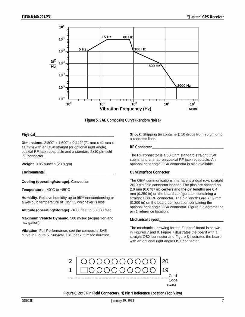
Vibration . Full Performance, see the composite SAEcurve in Figure 5. Survival, 18G peak, 5 msec duration.
Shock . Shipping (in container): 10 drops from 75 cm ontoa concrete floor.
RF Connector _______________________________________
The RF connector is a 50 Ohm standard straight OSXsubminiature, snap-on coaxial RF jack receptacle. Anoptional right angle OSX connector is also available.
OEM Interface Connector _____________________________
The OEM communications interface is a dual row, straight2x10 pin field connector header. The pins are spaced on2.0 mm (0.0787 in) centers and the pin lengths are 6.4mm (0.250 in) on the board configuration containing astraight OSX RF connector. The pin lengths are 7.62 mm(0.300 in) on the board configuration containing theoptional right angle OSX connector. Figure 6 diagrams thepin 1 reference location.
Mechanical Layout___________________________________
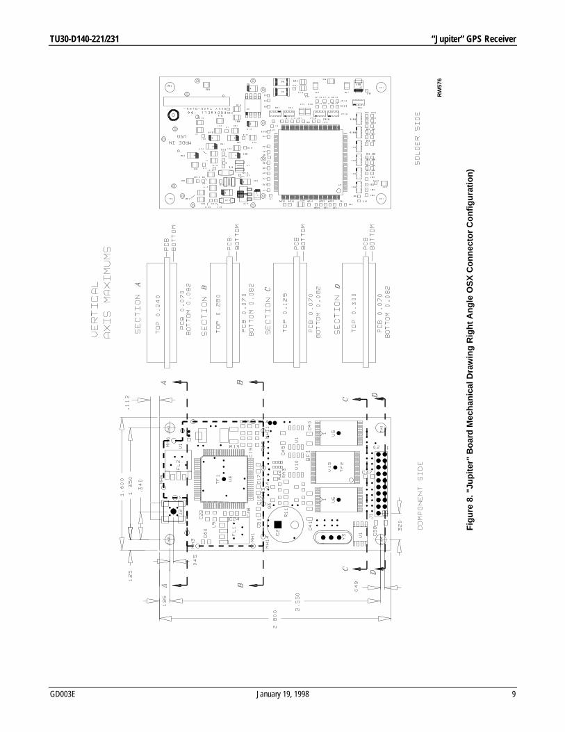
The mechanical drawing for the “Jupiter” board is shownin Figures 7 and 8. Figure 7 illustrates the board with astraight OSX connector and Figure 8 illustrates the boardwith an optional right angle OSX connector.
100
100
10-1
10-2
10-3
10-4
10-5
10-6
101 102 103 104
5 Hz
15 Hz 80 Hz
100 Hz
500 Hz
2000 Hz
RW301
G2 Hz
Vibration Frequency (Hz)
Figure 5. SAE Composite Curve (Random Noise)
202
191Card Edge
RW404
Figure 6. 2x10 Pin Field Connector (J1) Pin 1 Reference Location (Top VIew)

“Jupiter” GPS Receiver TU30-D140-221/231
8 January 19, 1998 GD003E
Fig
ure
7. "
Jupi
ter"
Boa
rd M
echa
nica
l Dra
win
g (S
trai
ght O
SX
Con
nect
or C
onfig
urat
ion)
RW
575
TU30-D140-221/231 “Jupiter” GPS Receiver
GD003E January 19, 1998 9
Fig
ure
8. "
Jupi
ter"
Boa
rd M
echa
nica
l Dra
win
g R
ight
Ang
le O
SX
Con
nect
or C
onfig
urat
ion)
RW
576

“Jupiter” GPS Receiver TU30-D140-221/231
10 January 19, 1998 GD003E
Hardware InterfaceThe electrical interface for the “Jupiter” receiver is astandard 2x10 pin field connector header that is used forall data input and output. A pinout description for thisconnector is provided in Table 4.
The following paragraphs describe the basic functionsallocated to the various pins on the 2x10 pin field interfaceconnector. These functions are divided into three groups:Configuration and timing signals, serial communicationsignals, and DC input signals.
Configuration And Timing Signals _____________________
Pin J1-5: Master Reset (M_RST)This signal allows the OEM to generate a systemhardware reset to the receiver. This signal is capable ofbeing driven directly by an external microprocessor or byexternal logic without the need for any external pull-up orpull-down resistors. The OEM can generate a systemreset to the receiver by pulling the M_RST control signallow to ground.
NOTE: The M_RST signal must be pulled to a CMOSlogic “high” level coincident with, or after, the applicationof prime DC power for the receiver to enter its Operatemode. The M_RST must be held at ground level for aminimum of 150 nanoseconds to assure propergeneration of a hardware reset to the receiver.
This signal can also be used to provide control of the“Jupiter” receiver’s Operate mode without removing primeinput power from the receiver. When M_RST is pulled toground, the receiver will enter a low power state for aslong as the M_RST signal is asserted low. In this state, aportion of the receiver’s RF circuitry is de-energized, theSRAMs are transitioned into their low power data retentionstate, and the RTC device is maintained. When the
receiver is placed into this low power state through theuse of the M_RST control signal, the receiver will continueto draw current from the primary input power (PWRIN) butat a reduced level.
When the M_RST signal is subsequently asserted high bythe OEM, RF power is re-applied, a system reset isgenerated, and the receiver will return to its normalOperate mode.
Pin J1-4: ReservedThis signal is reserved and NO electrical connectionsshould be made to the OEM application.
Pin J1-6: ReservedThis signal is reserved and NO electrical connectionsshould be made to the OEM application.
Pin J1-7: NMEA Protocol Select (GPIO2)The “Jupiter” receiver has two hardware selectablemessage protocols that may be used to communicateover the host serial I/O port. These message protocols area Rockwell binary message format and a NMEA ASCIImessage format. When this signal is pulled “low,” thereceiver communicates over the host serial port using theNMEA message format (4800 bps, no parity, 8 data bits,and 1 stop bit).
When this signal is pulled “high,” the receivercommunicates over the host serial I/O port using theformat determined by the setting of the Read-OnlyMemory (ROM) Default Select pin (J1-8).
Binary and NMEA messages are both described in theRockwell document, Zodiac GPS Receiver FamilyDesigner’s Guide.
The relationship between the user-selectable functions(GPIO2 and GPIO3) is shown in Table 5.
Table 4. “Jupiter” Receiver Standard 2x10 Pin Field OEM Interface Connector Pinout
PIN NAME DESCRIPTION PIN NAME DESCRIPTION
1 PREAMP Preamp power input 11 SDO1 Serial data output port #1
2 PWRIN_5 Primary +5 VDC power input 12 SDI1 Serial data input port #1
3 VBATT Battery backup voltage input 13 GND Ground
4 N/C Reserved (no connect) 14 N/C Reserved (no connect)
5 M_RST Master reset input (active low) 15 SDI2 Serial data input port #2
6 N/C Reserved (no connect) 16 GND Ground
7 GPIO2 NMEA protocol select 17 GND Ground
8 GPIO3 ROM default select 18 GND Ground
9 GPIO4 Reserved (no connect) 19 TMARK 1PPS time mark output
10 GND Ground 20 10KHZ 10 KHz clock output

TU30-D140-221/231 “Jupiter” GPS Receiver
GD003E January 19, 1998 11
Pin J1-8: ROM Default Select (GPIO3)This signal determines whether the message format, hostport communication settings, receiver default messageset, and initialization data parameters are obtained fromdefault values stored in ROM or from user-configurablesettings stored in SRAM/EEPROM. If this signal is pulled“low,” the ROM-based factory default values are used.
Note: when the ROM defaults select (GPIO3) signal ispulled “low,” each power cycle or reset of the receiver willresult in a longer TTFF. This is because the receiver willuse default initialization parameters stored in ROM ratherthan the current initialization parameters that may beavailable in SRAM or EEPROM.
The default values for NMEA protocol are 4800 bpsRX/TX, no parity, 8 data bits, and 1 stop bit. The defaultvalues for binary protocol are 9600 bps RX/TX, no parity,8 data bits, and 1 stop bit.
If this signal is pulled “high,” the port configurationparameters are accessed in the following priority:
1. If SRAM checksums are valid, the communicationparameters and initialization data parameters willbe read from SRAM.
2. If SRAM checksums are invalid and EEPROMchecksums are valid, the communicationparameters and initialization data parameters willbe read from EEPROM.
3. If SRAM checksums are invalid and EEPROMchecksums are invalid, the default values in ROMwill be used.
The relationship between the user-selectable functions(GPIO2 and GPIO3) is shown in Table 5.
Pin J1-9: Reserved (GPIO4)This signal is reserved and NO electrical connectionsshould be made to the OEM application.
Pin J1-14: ReservedThis signal is reserved and NO electrical connectionsshould be made to the OEM application.
Pin J1-19: UTC Time Mark Pulse (TMARK)The Time Mark output provides a one pulse-per-second (1pps) signal to the OEM application processor. When thereceiver provides a valid navigation solution, the risingedge of each TMARK pulse is synchronized with the UTCone second epochs to within ±1 microsecond.
The receiver software produces a binary format datamessage containing the UTC time associated with eachtime mark pulse. The relationship between the UTC TimeMark Pulse Output message and the TMARK pulse isshown in Figure 9. When the receiver’s serial datacommunication port is set to 9600 bps, the UTC TimeMark Pulse Output message preceeds the TMARK pulseby 400 to 500 milliseconds (typically).
The TMARK pulse waveform is shown in Figure 10. Thissignal is a positive logic, buffered CMOS level outputpulse that transitions from a logic “low” condition to a logic“high” at a 1 Hz rate. The TMARK output pulse rise time istypically less than 2 nanoseconds and the pulse durationis typically 25.6 milliseconds.
NMEA ProtocolSelect(pin 7)
ROM DefaultSelect(pin 8)
Result
0 0 NMEA message format; host port communication settings = 4800 bps, noparity, 8 data bits, 1 stop bit. The receiver operates from default initializationvalues stored in ROM and will output the default NMEA message set fromROM.
0 1 NMEA message format; host port communication settings = 4800 bps, noparity, 8 data bits, 1 stop bit. The receiver selects the default NMEA outputmessage set and uses initialization values from the data stored in SRAM orEEPROM (*).
1 0 Binary message format; host port communication settings = 9600 bps, noparity, 8 data bits, 1 stop bit. The receiver operates from default initializationvalues stored in ROM.
1 1 Data stored in SRAM or EEPROM determines message format, host portcommunication settings, and default message set (*).
(*) For further information, refer to the description of the ROM Default Select pin (J1-8) below.
Table 5. “Jupiter” Receiver Serial Port Configuration Truth Table

“Jupiter” GPS Receiver TU30-D140-221/231
12 January 19, 1998 GD003E
1 PPS
t t+1 t+2
msg 1108 t msg 1108 t +1 msg 1108 t +2Binary message 1108 data (*)
(*) Binary message data, 9600 bps, receiver reporting valid navigation solution
RW320
Figure 10. Jupiter GPS Receiver Time Mark Pulse Waveform
Figure 9. UTC Time Mark Pulse Output Message/UTC TMARK Pulse Relationship

TU30-D140-221/231 “Jupiter” GPS Receiver
GD003E January 19, 1998 13
Pin J1-20: 10 KHz UTC Synchronized ClockThis is a 10 KHz clock waveform that is synchronized tothe UTC TMARK pulse. The relationship between the 10KHz clock and the TMARK UTC pulse is shown in Figure11. This clock signal is a positive logic, buffered CMOSlevel output.
Serial Communication Signals ________________________
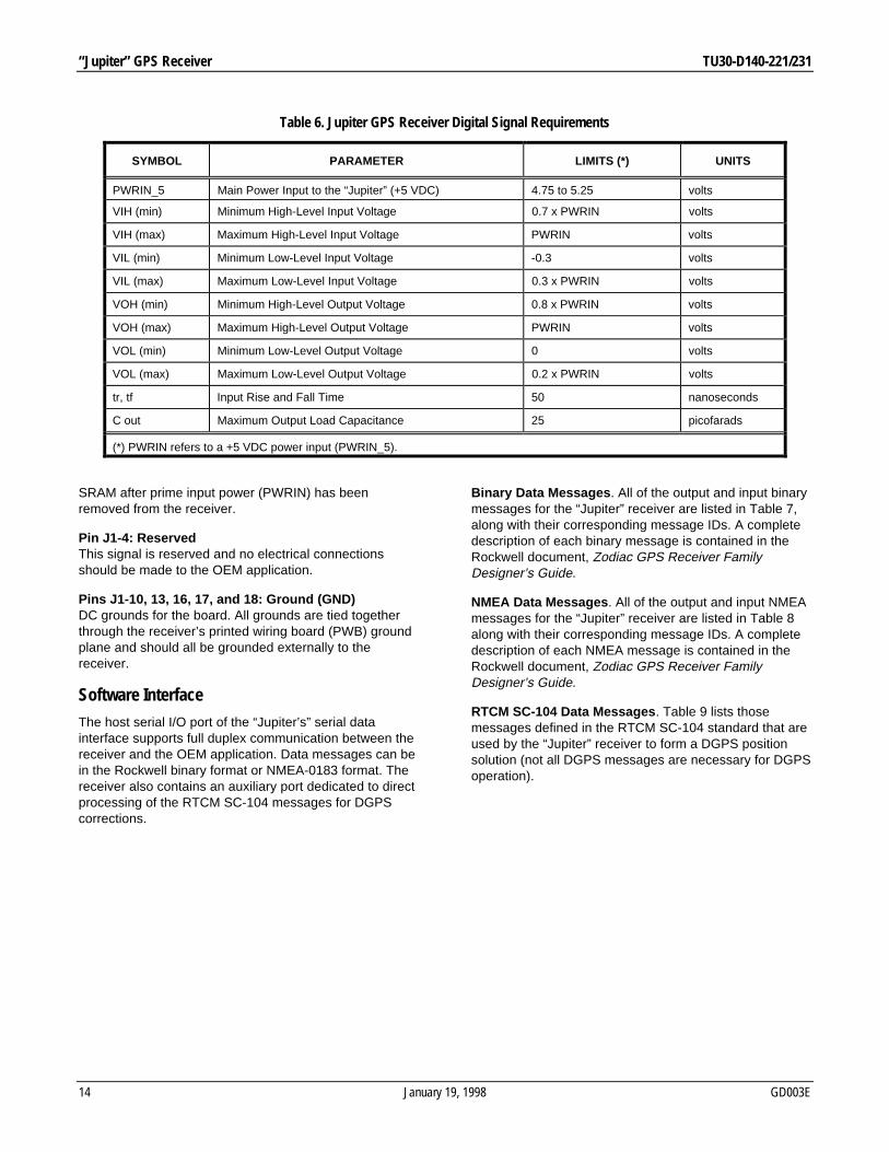
Note: both the Configuration and Timing signals,described in the previous section, and the SerialCommunication signals described below must be appliedaccording to the limits shown in Table 6.
Pins J1-11 and 12: Host Port Serial Data Output AndInput (SDO1 and SDI1)The host port consists of a full-duplex asynchronous serialdata interface. Both binary and NMEA initialization andconfiguration data messages are transmitted and receivedacross this port.
The OEM application must provide any Line Driver/LineReceiver (LD/LR) circuitry to extend the range of theinterface. Port Idle is nominally a CMOS logical high (+5VDC).
Pin J1-15: Auxiliary Port Serial Data Input (SDI2)The auxiliary port consists of a second half-duplexasynchronous serial data interface. This port is configuredto receive RTCM DGPS correction data messages.
The OEM application must provide any LD/LR circuitry toextend the range of the interface. Port Idle is nominally aCMOS logical high (+5 VDC).
DC Input Signals ____________________________________
Pin J1-1: Preamp Power Input (PREAMP)The OEM may optionally supply power to a preamplifierusing the antenna cable center conductor. The maximumvoltage is +12 VDC and the current must not exceed 100mA.
WARNING: DO NOT APPLY POWER TO A PASSIVEANTENNA OR DAMAGE TO THE RECEIVER WILLOCCUR.
Pin J1-2: Power Input (PWRIN_5)This signal is the main power input to the “Jupiter”receiver. Regulated DC power requirements are shown inTable 3.
Pin J1-3: Battery Backup Power Input (VBATT)This signal is used to provide a DC power input to theSRAM and RTC devices only. The receiver automaticallyswitches to the VBATT input signal when primary DCpower (PWRIN) is removed from the board.
This feature is intended to provide the receiver with a“warm start” capability by maintaining an accurate timesource and using position and satellite data stored in
RW305
Figure 11. 10 KHz Clock/UTC TMARK Pulse Relationship
“Jupiter” GPS Receiver TU30-D140-221/231
14 January 19, 1998 GD003E
SRAM after prime input power (PWRIN) has beenremoved from the receiver.
Pin J1-4: ReservedThis signal is reserved and no electrical connectionsshould be made to the OEM application.
Pins J1-10, 13, 16, 17, and 18: Ground (GND)DC grounds for the board. All grounds are tied togetherthrough the receiver’s printed wiring board (PWB) groundplane and should all be grounded externally to thereceiver.
Software InterfaceThe host serial I/O port of the “Jupiter’s” serial datainterface supports full duplex communication between thereceiver and the OEM application. Data messages can bein the Rockwell binary format or NMEA-0183 format. Thereceiver also contains an auxiliary port dedicated to directprocessing of the RTCM SC-104 messages for DGPScorrections.
Binary Data Messages . All of the output and input binarymessages for the “Jupiter” receiver are listed in Table 7,along with their corresponding message IDs. A completedescription of each binary message is contained in theRockwell document, Zodiac GPS Receiver FamilyDesigner’s Guide.
NMEA Data Messages . All of the output and input NMEAmessages for the “Jupiter” receiver are listed in Table 8along with their corresponding message IDs. A completedescription of each NMEA message is contained in theRockwell document, Zodiac GPS Receiver FamilyDesigner’s Guide.
RTCM SC-104 Data Messages . Table 9 lists thosemessages defined in the RTCM SC-104 standard that areused by the “Jupiter” receiver to form a DGPS positionsolution (not all DGPS messages are necessary for DGPSoperation).
Table 6. Jupiter GPS Receiver Digital Signal Requirements
SYMBOL PARAMETER LIMITS (*) UNITS
PWRIN_5 Main Power Input to the “Jupiter” (+5 VDC) 4.75 to 5.25 volts
VIH (min) Minimum High-Level Input Voltage 0.7 x PWRIN volts
VIH (max) Maximum High-Level Input Voltage PWRIN volts
VIL (min) Minimum Low-Level Input Voltage -0.3 volts
VIL (max) Maximum Low-Level Input Voltage 0.3 x PWRIN volts
VOH (min) Minimum High-Level Output Voltage 0.8 x PWRIN volts
VOH (max) Maximum High-Level Output Voltage PWRIN volts
VOL (min) Minimum Low-Level Output Voltage 0 volts
VOL (max) Maximum Low-Level Output Voltage 0.2 x PWRIN volts
tr, tf Input Rise and Fall Time 50 nanoseconds
C out Maximum Output Load Capacitance 25 picofarads
(*) PWRIN refers to a +5 VDC power input (PWRIN_5).

TU30-D140-221/231 “Jupiter” GPS Receiver
GD003E January 19, 1998 15
Output Message Name Message IDGeodetic Position Status Output (*) 1000
Channel Summary (*) 1002
Visible Satellites (*) 1003
Differential GPS Status 1005
ECEF Position Output 1009
Receiver ID (**) 1011
User-Settings Output 1012
Built-In Test Results 1100
UTC Time Mark Pulse Output (*) 1108
Serial Port Communication Parameters In Use 1130
EEPROM Update 1135
EEPROM Status 1136
Input Message Name Message IDGeodetic Position and Velocity Initialization 1200
User-Defined Datum Definition 1210
Map Datum Select 1211
Satellite Elevation Mask Control 1212
Satellite Candidate Select 1213
Differential GPS Control 1214
Cold Start Control 1216
Solution Validity Criteria 1217
User-Entered Altitude Input 1219
Application Platform Control 1220
Nav Configuration 1221
Perform Built-In Test Command 1300
Restart Command 1303
Serial Port Communication Parameters 1330
Message Protocol Control 1331
Raw DGPS RTCM SC-104 Data 1351
(*) Enabled by default at power-up
(**) Once at power-up/reset
Table 7. “Jupiter” Receiver Binary Data Messages

“Jupiter” GPS Receiver TU30-D140-221/231
16 January 19, 1998 GD003E
Table 8. “Jupiter” Receiver NMEA Data Messages
Output Message Name Message IDRockwell Proprietary Built-In Test (BIT) Results BIT
GPS Fix Data (*) GGA
GPS DOP and Active Satellites (*) GSA
GPS Satellites in View (*) GSV
Track Made Good and Ground Speed VTG
Recommended Minimum Specific GPS Data (*) RMC
Rockwell Proprietary Receiver ID (**) RID
Rockwell Proprietary Zodiac Channel Status (*) ZCH
Input Message Name Message IDRockwell Proprietary Built-In Test (BIT) Command IBIT
Rockwell Proprietary Log Control Message ILOG
Rockwell Proprietary Receiver Initialization INIT
Rockwell Proprietary Protocol Message IPRO
Standard Query Message Q
(*) Default power-up message
(**) Once at power-up/reset

TU30-D140-221/231 “Jupiter” GPS Receiver
GD003E January 19, 1998 17
Information provided by Rockwell International Corporation is believed to be accurate and reliable. However, no responsibility is assumed byRockwell International for its use, nor any infringement of patents or other rights of third parties which may result from its use. No license isgranted by implication or otherwise under any patent rights of Rockwell International other than for circuitry embodied in Rockwell products.Rockwell International reserves the right to change circuitry at any time without notice. This document is subject to change without notice.
Table 9. “Jupiter” Receiver RTCM SC-104 Data Messages
Message ID Status (*) Title Used For DGPS Corrections?1 F Differential GPS Corrections Y
2 F Delta DGPS Corrections Y
3 F Reference Station Parameters N
4 R Surveying (message retired) N
5 F Constellation Health N
6 F Null Frame N
7 F Beacon Almanacs N
8 T Pseudolite Almanacs N
9 F Partial Satellite Set Differential Corrections Y
10 R P-Code Differential Corrections N
11 R CA Code L1/L2 Delta Corrections N
12 R Pseudolite Station Parameters N
13 T Ground Transmitter Parameters N
14 R Surveying Auxiliary Message N
15 R Ionosphere (Troposphere) Message N
16 F Special Message N
17 T Ephemeris Almanac N
18 T Uncorrected Carrier Phase Measurements N
19 T Uncorrected Pseudorange Measurements N
20 T RTK Carrier Phase Corrections N
21 T RTK Pseudo-Range Corrections N
22-58 Undefined N
59 T Proprietary Message N
60-63 R Multi-Purpose Usage N
(*) “F” = Fixed, “T” = Tentative, and “R” = Reserved. Status types are defined in Table 4.3 of the RTCM SC-104 version 2.1 standard.

Worldwide HeadquartersRockwell Semiconductor Systems4311 Jamboree Road,P.O. Box CNewport Beach, CA 92658-8902Phone: (714) 221-4600Fax: (714) 221-6375
For more information:Call 1-800-854-8099International information:Call 1-714-221-6996
URL Address:http://www.rss.rockwell.comE-Mail Address:[email protected]
REGIONAL SALES OFFICESUS Northwest/Pacific NorthwestRockwell Semiconductor SystemsUS Northwest Office3600 Pruneridge AvenueSuite 100Santa Clara, CA 95051Phone: (408) 249-9696Fax: (408) 249-7113US Los AngelesRockwell Semiconductor Systems1000 Business Center CircleSuite 215Thousand Oaks, CA 91320Phone: (805) 376-0559Fax: (805) 376-8180US SouthwestRockwell Semiconductor Systems5000 Birch StreetSuite 400Newport Beach, CA 92660Phone: (714) 222-9119Fax: (714) 222-0620
US North CentralRockwell Semiconductor SystemsTwo Pierce PlaceChancellory ParkSuite 810Itasca, IL 60143Phone: (630) 773-3454Fax: (630) 773-3907US South CentralRockwell Semiconductor Systems2001 North Collins BlvdSuite 103Richardson, TX 75080Phone: (972) 479-9310Fax: (972) 479-9317US NortheastRockwell Semiconductor Systems239 Littleton RoadSuite 4AWestford, MA 01886Phone: (508) 692-7660Fax: (508) 692-8185US SoutheastRockwell Semiconductor Systems3500 Parkway Lane, Suite 415Norcross, GA 30092Phone: (770) 246-8283Fax: (770) 246-0018US Florida/South AmericaRockwell Semiconductor SystemsOne Prestige Place2600 McCormick DriveSuite 350Clearwater, FL 33759Phone: (813) 799-8406Fax: (813) 799-8306US Mid-AtlanticRockwell Semiconductor SystemsPrinceton Pike Corporate Center993 Lenox Drive, Suite 200Lawrenceville, NJ 08648Phone: (609) 219-7462Fax: (609) 895-2666
European HeadquartersRockwell Semiconductor Systems S.A.S.Les Taissounieres B11680 Route des DolinesBP 28306905 Sophia Antipolis CedexFrancePhone: (33) 4 93 00 33 35Fax: (33) 4 93 00 33 03Europe CentralRockwell Int'l GmbH,Rockwell Semiconductor Systems BranchPaul-Gerhardt-Allee 50 a81245 MünchenGermanyPhone: (49-89) 829-1320Fax: (49-89) 834-2734Europe MediterraneanRockwell Semiconductor Systemsc/o Rockwell Automation S.r.l.Via G. Di Vittorio, 120017 Mazzo Di Rho (MI)ItalyPhone: (39 2) 93179911Fax (39 2) 93179913Europe NorthRockwell Semiconductor Systems, Ltd.Berkshire CourtWestern RoadBracknellBerkshire RG12 1REEnglandPhone: 44 (0) 1344 486444Fax: 44 (0) 1344 486555Europe North (Satellite)Rockwell Semiconductor Systems Israel, Ltd.(RSSI)11 Galgaley Haplada StreetP.O. Box 12660Herzlia 46733IsraelPhone: (972) 9 9524000Fax: (972) 9 9573732
Europe SouthRockwell Semiconductor Systems S.A.S.Tour GANCedex 1392082 Paris La Défense 2FrancePhone: (33) 1 49 06 39 80Fax: (33) 1 49 06 39 90APAC HeadquartersRockwell Int’l Manufacturing Pte Ltd1 Kim Seng Promenade#09-01 East TowerGreat World CitySingapore 237994Phone: (65) 737-7355Fax: (65) 737-9077AustraliaRockwell Australia Pty LimitedSuite 603, 51 Rawson StreetEpping, NSW 2121AustraliaPhone: (61-2) 9869 4088Fax: (61-2) 9869 4077
ChinaRockwell Semiconductor Systems Worldwide,Inc.Shanghai Representative OfficeLT Square Building, Suite 3002500 Chengdu North RoadShanghai 200003 P.R.C.Phone: 86-21-6361-2515Fax: 86-21-6361-2516Hong KongRockwell Int'l (Asia Pacific) Ltd.13th Floor, Suites 8-10,Harbour Centre25 Harbour RoadWanchai,Hong KongPhone: (852) 2 827-0181Fax: (852) 2 827-6488
IndiaRockwell Int’l Overseas CorporationRegional Office - South AsiaCapital Trust House47 Community CentreFriends ColonyNew Delhi - 110 065IndiaPhone: (91-11) 692-4780Fax: (91-11) 692-4712KoreaRockwell Collins Int'l, Inc.Room No. 1508Korea Textile Centre Building944-31, Daechi-3dongKangnam P.O. Box 2037Kangnam-kuSeoulKoreaPhone: (82-2) 565-2880Fax: (82-2) 565-1440Taiwan HeadquartersRockwell Int'l Taiwan Company, Ltd.Room 2808 International Trade Bldg.333, Keelung Road, Section ITaipei,Taiwan10548 ROCPhone: (886-2) 720-0282Fax: (886-2) 757-6760Japan HeadquartersRockwell Int'l Japan Co., Ltd.Shimomoto Bldg1-46-3 Hatsudai, Shibuya-kuTokyo, 151JapanPhone: (81-3) 5371 1520Fax: (81-3) 5371 1501
SOUD110497
©1997, Rockwell International CorporationPrinted in U.S.A.All Rights Reserved