justin treptow alex morrese alexis mendez casselle russell john klaus robert cooper thilina fernando...
TRANSCRIPT

Justin Treptow Alex MorreseAlexis MendezCasselle Russell
John KlausRobert CooperThilina FernandoZoe Morozko
Faculty Advisors: Dr. Dan KirkGreg Peebles
Paul Martin Ben BurnettShriman ShivaDamian Harasiuk
1
Develop “Mission Plan” with in 4 years, minimum expense, with no military or heritage hardware
Establish a program that continues beyond our graduation
Bring useful talent into the program such as: Universities, Professionals, Graduates
2
Land in GLXP approved landing site near a Historical Artifact
Traverse 500m in a deliberate manner around a Historic Artifact
Transmit minimum dataset to earth On arrival Mooncast > 500MB Mission Complete Mooncast > 500MB
3

On Arrival Mooncast
• Descent Video > 2min. Near Real Time (NRT) transmitted ASAP• Camera shot vertically or horizontally• Arrival Video (Landing Site and Environment) > 30sec NRT transmitted ASAP• Post Arrival Images: Panorama, 3 self portraits depicting 40% of craft, GLXP Logo Cluster and Lunar surface• Transmit video message, email, text message• NRT video > 6 min, shot from various angles• HD video > 6 min, shot from various angles
4

Mission Complete Mooncast
NRT departure video > 30 sec, transmitted ASAP, shot of transition onto lunar surface
NRT looking back video > 30 sec, transmitted ASAP, shot of original landing site as vehicle moves away
Looking back photo depicting landing location NRT Mid-Journey video > 30 sec, transmitted ASAP, shot while
transversing Mid-Journey photo at 250 m from landing site depicting > 40% of rover
surface Journey’s End Panoramic at 500m with lander/landing sight in view Journey’s End Self Portrait portraying > 40% of transversing vehicle 3 Journey’s End photos of logo cluster and moonscape NRT video > 5min, shot from various angles HD video > 5 min, shot from various angles
5

Design Requirements
System
System Drivers
(Metrics)Analysi
s
Trade Study
Design Conflict
s
Big Picture
System
Level
Subsystem Level
Interface Level
System Drivers
(Metrics)Analysi
s
Trade Study
Sub -System
System Drivers
(Metrics)Analysi
s
Trade Study
Interface
6
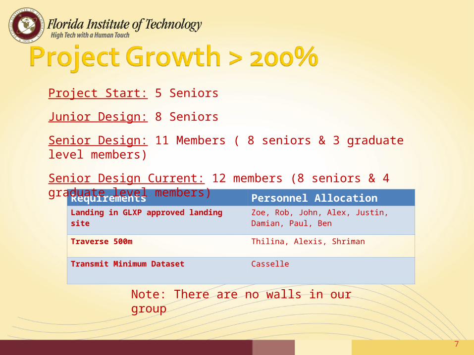
Requirements Personnel AllocationLanding in GLXP approved landing site Zoe, Rob, John, Alex, Justin, Damian, Paul, Ben
Traverse 500m Thilina, Alexis, Shriman
Transmit Minimum Dataset Casselle
Note: There are no walls in our group
Project Start: 5 Seniors
Junior Design: 8 Seniors
Senior Design: 11 Members ( 8 seniors & 3 graduate level members)
Senior Design Current: 12 members (8 seniors & 4 graduate level members)
7

Launch Vehicle Trade Study
8
Properties Delta II Atlas V - 401 Zenit 3SL Falcon 1 Pegasus XL Dnepr Payload to LEO (kg) ~6,096 9,750 ~7,000 723 454 3700Cost (millions of dollars) 50 75 70 7 16 9.5Reliability (success rate, %) 99% 100% 97% 0% 87% 97%
Launch Location (distance to equator, km) ~3165 km (Cape)
~3165 km (Cape)
Equator (0 km)
~3165 km (Cape) The sky Baikonur,
Kazakhstan
Weight% Scores
Payload to LEO (kg) 0.4 4 10 8 3 1 6Cost (millions of dollars) 0.35 5 1 2 10 8 9Reliability (success rate, %) 0.2 9 10 8 1 7 8Launch Location (dist. to equator, km) 0.05 8 8 10 8 10 7
1.6 4 3.2 1.2 0.4 2.41.75 0.35 0.7 3.5 2.8 3.151.8 2 1.6 0.2 1.4 1.60.4 0.4 0.5 0.4 0.5 0.35
Overall 5.55 6.75 6 5.3 5.1 7.5
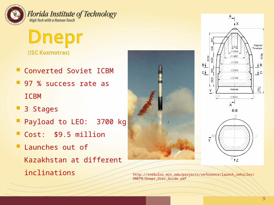
Converted Soviet ICBM
97 % success rate as ICBM
3 Stages
Payload to LEO: 3700 kg
Cost: $9.5 million
Launches out of Kazakhstan
at different inclinations
http://snebulos.mit.edu/projects/reference/launch_vehicles/DNEPR/Dnepr_User_Guide.pdf
9

Inclination = 50.5Inclination =64.5Inclination = 87.3Inclination = 98 10
Inclination (i) Orbit inclination with respect to earth’s equator
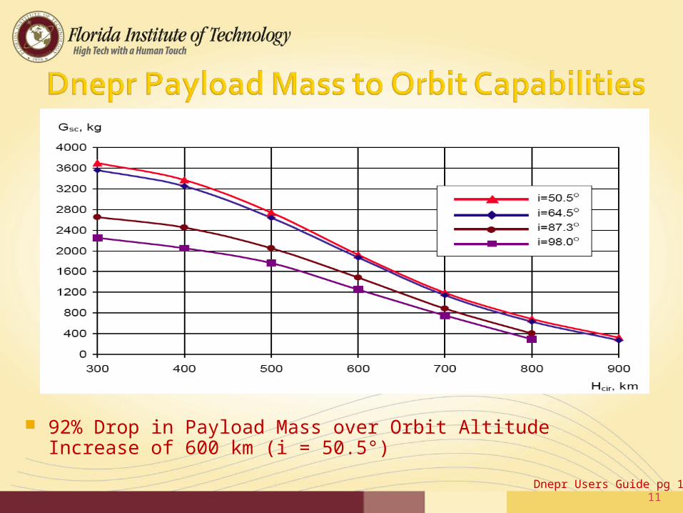
92% Drop in Payload Mass over Orbit Altitude Increase of 600 km (i = 50.5°)
Dnepr Users Guide pg 1911
Hohmann Transfer is the preferred method
Ion propulsion’s time scale is outside of mission requirements
SMART -1 ion propelled mission took 13 months
12

PurposeTo develop a analytic tool that accelerated analysis or
Hohmann Transfers
Input (Design Specifications)Orbit altitudeISPMass to be at final location
Output (System Drivers)Total & Incremental ΔVTotal Propellant Mass RequiredMass Ratio
13
Δv: velocity change required to alter the orbit of a space craft
From these results:▪ Velocity can be determined at a specific point
along the trajectory ▪ Mass of the fuel required will aid in tank
design requirements▪ Mass available for landing will allow for
payload mass estimates
14

Acquired Satellite Tool Kit (STK) Using the Astrogator Suite $100,000.00 value
Utilized by: Lockheed Martin, Northrop Grumman, NORAD, Florida Institute of Technology (Dana Carmody), ect.
Paul Martin is taking point with the simulation with oversight from senior design team members
Capacity to model complete mission simulation Launch – Mission Complete
Images provided by AGI.com
15

What orbit altitude corresponds to most efficient use of Dnepr’s lifting capabilities and propellant in spacecraft?
ΔV variations occur when transferring from a circular earth orbit to an elliptical earth orbit with apoapsis at L1 point.
300km
600km
900km
• L1: location where gravitational force from earth and moon are equal
L1
16

Orbit Altitude (km)
Circular Earth Orbit Velocity (km/s)
Required Velocity at Periapsis of Elliptic Orbit (km/s)
ΔV (km/s)
Dnepr Mass Delivered
(kg)
300 7.73 10.81 3.58 3700
400 7.67 10.73 3.06 3300
500 7.61 10.65 3.04 2800
600 7.56 10.57 3.01 1900
700 7.50 10.50 3.00 1200
800 7.45 10.42 2.97 700
900 7.40 10.35 2.95 300
• Maximum ΔV difference of 0.63km/s, 17.6% change
17

• Large change in orbiting mass for small change in ΔV.• Best to use Dnepr to launch between 3300kg and 3700kg mass into orbit 18

Fuel
Specific Volume (m3/kg) Oxidizer
Specific Volume (m3/kg)
Mixture Ratio (Ox:Fuel) Isp (s) MR
Liquid Bi- Propellants
Hydrogen 1.41E-02 Oxygen 8.77E-04 5 390 4.12
Kerosene 1.34E-03 Oxygen 8.77E-04 2.29 301 6.25
Hydrazine 9.96E-04 Oxygen 8.77E-04 0.74 313 5.83
MMH 1.15E-03 Nitrogen Tetroxide 6.90E-04 1.73 280 7.18
UDMH 1.26E-03 Nitrogen Tetroxide 6.90E-04 2.1 277 7.33
Liquid Mono-propellants
Hydrazine 9.96E-04 - - - 199 16.00
Hydrogen Peroxide 6.94E-04 - - - 165 28.34
Solid Propellants
Aluminum+HTPB Ammonium
Perchlorate 5.12E-04 2.12 267 7.90
Aluminum+PBAN Ammonium
Perchlorate 5.12E-04 2.33 266 7.96
• Mass Ratio based on total Δv of 5.42km/s
Spacecraft System Engineering. 3rd ed. Fortescue, P. pg 183http://www.braeunig.us/space/propel.htmhttp://www.astronautix.com/ROCKET PROPELLANTS, Warren FA, Reinhold Pubising 1958
19
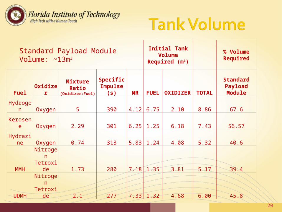
Initial Tank Volume Required
(m3)
% Volume Required
Fuel OxidizerMixture Ratio
(Oxidizer:Fuel)
Specific Impulse (s) MR FUEL OXIDIZER TOTAL
Standard Payload Module
Hydrogen Oxygen 5 390 4.12 6.75 2.10 8.86 67.6
Kerosene Oxygen 2.29 301 6.25 1.25 6.18 7.43 56.57
Hydrazine Oxygen 0.74 313 5.83 1.24 4.08 5.32 40.6
MMHNitrogen Tetroxide 1.73 280 7.18 1.35 3.81 5.17 39.4
UDMHNitrogen Tetroxide 2.1 277 7.33 1.32 4.68 6.00 45.8
Standard Payload Module Volume: ~13m3
20
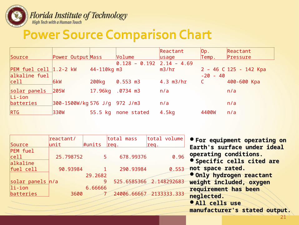
For equipment operating on For equipment operating on Earth's surface under ideal Earth's surface under ideal operating conditions.operating conditions.Specific cells cited are not Specific cells cited are not space rated.space rated.Only hydrogen reactant Only hydrogen reactant weight included, oxygen weight included, oxygen requirement has been requirement has been neglected.neglected.All cells use manufacturer's All cells use manufacturer's stated output.stated output.
Source Power Output Mass Volume Reactant usage Op. Temp. Reactant Pressure
PEM fuel cell 1.2-2 kW 44-110kg 0.128 – 0.192 m3 2.14 – 4.69 m3/hr 2 – 46 C 125 - 142 Kpa
alkaline fuel cell 6kW 200kg 0.553 m3 4.3 m3/hr -20 - 40 C 400-600 Kpa
solar panels 205W 17.96kg .0734 m3 n/a n/a
Li-ion batteries 300-1500W/kg 576 J/g 972 J/m3 n/a n/a
RTG 330W 55.5 kg none stated 4.5kg 4400W n/a
21
Source reactant/unit #units total mass req. total volume req.
PEM fuel cell 25.798752 5 678.99376 0.96
alkaline fuel cell 90.93984 1 290.93984 0.553
solar panels n/a 29.26829 525.6585366 2.148292683
li-ion batteries 3600 6.666667 24006.66667 2133333.333
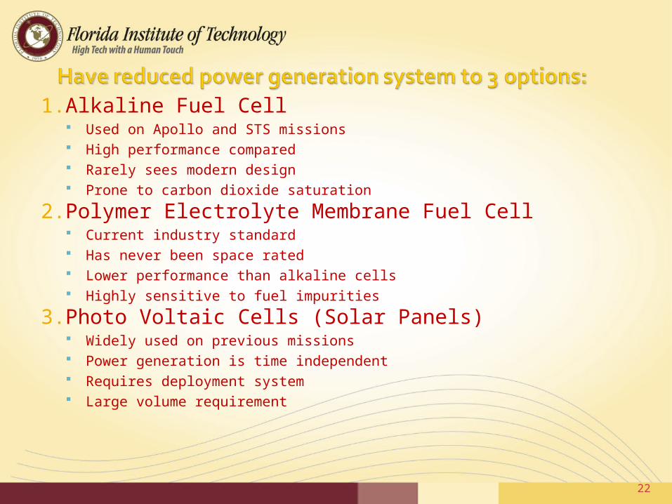
1. Alkaline Fuel Cell Used on Apollo and STS missions High performance compared Rarely sees modern design Prone to carbon dioxide saturation
2. Polymer Electrolyte Membrane Fuel Cell Current industry standard Has never been space rated Lower performance than alkaline cells Highly sensitive to fuel impurities
3. Photo Voltaic Cells (Solar Panels) Widely used on previous missions Power generation is time independent Requires deployment system Large volume requirement
22

Site Latitude Longitude Comments Apollo 11 Landing 1N 24E First manned moon mission
Apollo 12 Landing 3S 24W
Apollo 12 LEM impact 4S 21W
Apollo 13 Saturn IVB impact 3S 19W Only mission success during Apollo 13
Apollo 14 Landing 4S 18W Allan Shepherd plays golf
Apollo 14 LEM impact 3S 20W
Apollo 14 S-IVB impact 8S 26W
Apollo 15 Landing 26N 5E Used modular equipment transporter
Apollo 15 LEM impact 26N 1E
Apollo 15 S-IVB impact 2S 11W
Apollo 16 Landing 9S 16E First mission to use the lunar roving vehicle
Apollo 16 S-IVB impact 1N 24W
Apollo 17 Landing 21N 31E Last manned moon mission
Apollo 17 LEM impact 21N 31E Used lunar roving vehicle
Apollo 17 S-IVB impact 5S 13W
23

The goal has been made; land at the location of the first Apollo manned Moon landing, Apollo 11
Luna 20
Luna 16
24
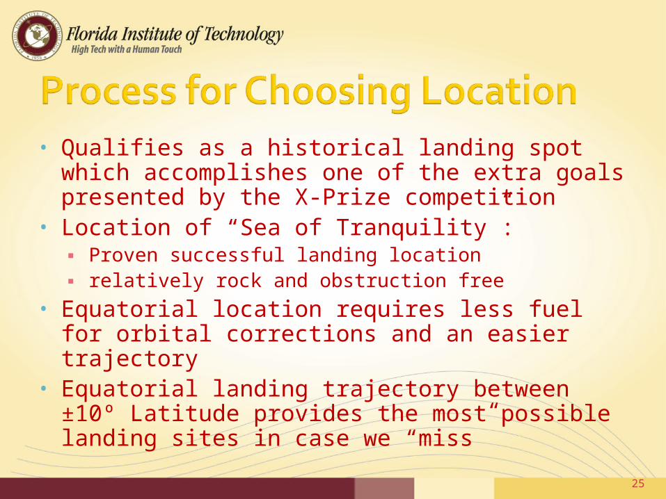
• Qualifies as a historical landing spot which accomplishes one of the extra goals presented by the X-Prize competition
• Location of “Sea of Tranquility”:▪ Proven successful landing location▪ relatively rock and obstruction free
• Equatorial location requires less fuel for orbital corrections and an easier trajectory
• Equatorial landing trajectory between ±10º Latitude provides the most possible landing sites in case we “miss”
25

Motors Manufacture Model Power S/RDrive motors Maxon Motors RE-max 29 15W 48V 0.283A
1.59A (Starting )Upon Request
Steering motors Maxon Motors RE-max 21 6W 48V 0.151A 0.598A(starting)
Upon Request
Cameras
HD 11.16 W (max estimation)
No
SD =16.8 W (max estimation)
No
•Tentative power budget based on selection of components. •Research into cameras and other onboard electronics is on going.•Given this, a total consumption of 150 watts will be estimated.•This is based on the power consumption of previous rovers that have been designed.
26
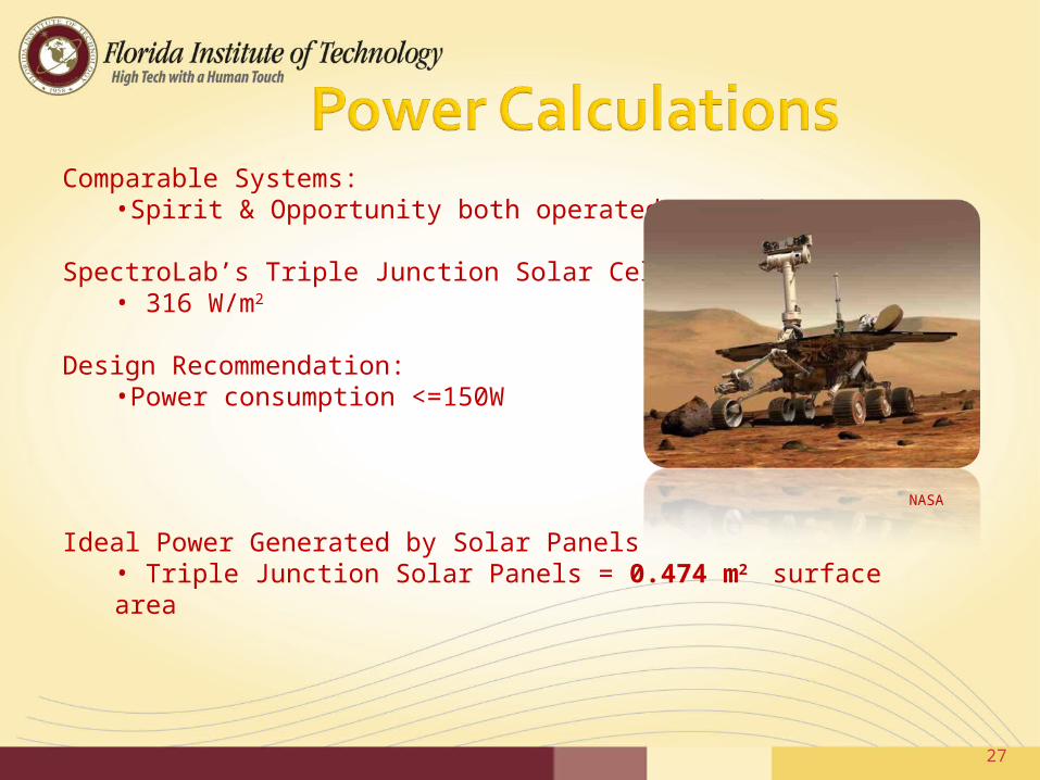
Comparable Systems:•Spirit & Opportunity both operated at 150W
SpectroLab’s Triple Junction Solar Cell• 316 W/m2
Design Recommendation:•Power consumption <=150W
27
NASA
Ideal Power Generated by Solar Panels• Triple Junction Solar Panels = 0.474 m2 surface area

Lunar Conditions ≠ Ideal• Direct solar Radiation • Panels above normal operating conditions,• Loose efficiency.
Assumptions: Solar Radiation Sc = 1353 W/m2
Emissivity of Solar Panels 0.85 Temp Lunar Environment 107⁰C
Analytical Analysis (Radiation Transfer) Panel Surface Temp Ts = 197°C Voltage drop 1.13v/cm2 Negligible Current Increase 1.24*10-4 Amp
These losses will have to be compensated by including extra Solar Cells
28
Parameters that determine performance:
Radiation SusceptibilityPower ConsumptionOperation TemperaturesMassResolution Frame Rate
29

30
Requirements for HD camera 720p resolution 1280x720 pixels 15 frames a sec minimum
Requirements for SD camera Near real time transmission 15 frames a sec minimum Always on

CAMERA COST ($) POWER OPERATING TEMP MASS
BODY ADAPT BATTCanon EOS Digital Rebel XS
Standard DefinitionCMOS Sensor
800 TYPE: Rechargeable Lithium Ion
VOLTAGE: 7.4V DCCAPACITY: 1080mAhLIFE: 500-600 shots{NO FLASH]400-500[50% FLASH]
0-40˚C(32-104 ˚F)
475g (16.8oz) 80g (2.8oz)
Canon VIXIA HF10High Definition 1080i
810 SUPPLY: 100-240V AC,50/60HzOUTPUT: 8.4V DC,1.5A
0-40˚C(32-104 ˚F)
380g (13.4oz) 135g (4.8oz)
Nikon D40Standard Definition
CCD
480 TYPE: Lithium IonVOLTAGE:7.4V DCCAPACITY:1000mAh
0-40˚C(32-104 ˚F)
475g (17oz) 51g (1.8oz)
Panasonic HDC SD9High Definition 1080i
CCD
650 SUPPLY:110-240V AC, 50/60HzOUTPUT: 9.3V DC, 1.2A
0-40˚C(32-104 ˚F)
275g (9.7oz) 115g (4.0oz)
Sony Alpha DSLR-A200Standard Definition
CCD
500 TYPE: Lithium IonVOLTAGE: 8.4V DC, 2.0ACAPACITY:1650mAh
0-40˚C(32-104 ˚F)
532g (18.8oz) 78g (2.8oz)
Sony Alpha DSLR-A350Standard Definition
CCD
800 TYPE: Lithium IonVOLTAGE: 8.4V DC, 2.0ACAPACITY: 1650mAh
0-40˚C(32-104 ˚F)
582g (20.5oz) 78g (2.8oz)
Sony HDR-HC9High Definition 1080i
CMOS
980 SUPPLY:100-240V AC, 50/60HzOUTPUT: 8.4V DC, 0.35-0.18A
0-40˚C(32-104 ˚F)
550g (1lb 3oz) 170g (6.0oz)
Sony HDR-SR12High Definition 1080i
CMOS
1150 SUPPLY: 100-240V AV, 50/60HzOUTPUT:8.4V DC, 0.35-0.18A
0-40˚C(32-104 ˚F)
570g (1lb 4oz) 170g (6.0oz)
Camera Analysis
31
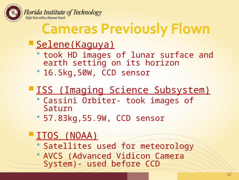
Selene(Kaguya) took HD images of lunar surface and
earth setting on its horizon 16.5kg,50W, CCD sensor
ISS (Imaging Science Subsystem) Cassini Orbiter- took images of Saturn 57.83kg,55.9W, CCD sensor
ITOS (NOAA) Satellites used for meteorology AVCS (Advanced Vidicon Camera
System)- used before CCD32
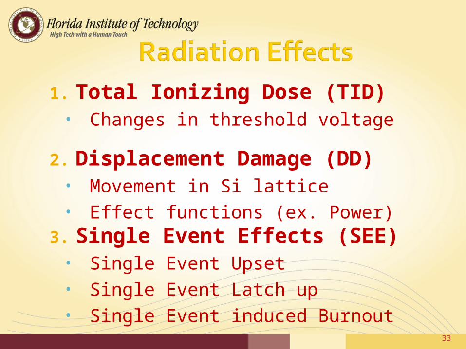
1. Total Ionizing Dose (TID)• Changes in threshold voltage
2. Displacement Damage (DD)• Movement in Si lattice• Effect functions (ex. Power)
3. Single Event Effects (SEE) • Single Event Upset• Single Event Latch up• Single Event induced Burnout
33

CCD camera w/o RH CCD camera w/ RH
t=0 (100Gy/hr)
t=1hr (100Gy/hr)
34

Radiation Hardening Techniques Physical-
▪ Microchips that are made from insulating substances (Silicone Oxide & Sapphire)
▪ Shielding the package or the chips themselves (depleted Boron)
▪ Using components with a wide band gap Logical-
▪ Error correction (parity check)▪ Redundant elements
35

Option 1 Design Electronics with hardening
in mind Option 2 Shield commercial electronics
Case study will be performed to select
36

System (with 4 wheels)
total # of Joints
# springs and dampers
Wheel travel
Rocker Bogie 2 differential joints
0 Depends on design
Independent suspension
24 (6 per wheel)
4 springs 4 dampers
Limited by the spring or damper
Source: Heiken et al, Lunar Source Book Cambridge university press 1991
System Drivers: Complexity, Mass, Vehicle Velocity
Current Conclusion•Rocker Bogie System
4 wheel Rocker Bogie system selected
No springs or dampers Has the greatest wheel travelLeast number of jointsProven history
37

Wheel DesignLiterature review of mechanical properties of lunar regolith Recommended ground pressure of 7-10 Kpa for wheeled vehicles
38
Complete trafficability calculations Wheel sinkage Gross pull per Wheel Soil resistance per wheel
Perform kinematic analysis on the Rocker Bogie and fine tune the design to fit our particular needs.
39

40
Launch Vehicle
Orbital Dynamics
Transfer Vehicle
Lander
End Fall 08
Big Picture
System
Sub System
Interface
End Spring 09
2 Iterations
3 Iteration >2
Iterations
0 Iterations

41
Big Picture
System
Sub System
Interface
Rover Power Imaging Communications
2 Iterations
2 Iteration
1 Iterations
End Fall 08
End Spring 09
Roving Vehicle
1 Iterations
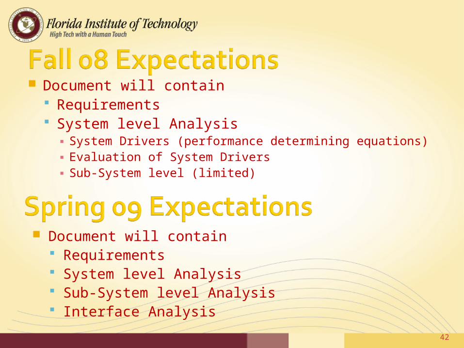
Document will contain Requirements System level Analysis
▪ System Drivers (performance determining equations)▪ Evaluation of System Drivers▪ Sub-System level (limited)
Document will contain Requirements System level Analysis Sub-System level Analysis Interface Analysis
42
43