juvo - recare.co.uk
TRANSCRIPT

JuvoInstructions for use (user) ...................................................................................... 3

2 Juvo
Foreword1 7..............................................................................................................................................................Product description2 8............................................................................................................................................Function2.1 8..............................................................................................................................................Product overview2.2 9..................................................................................................................................
Safety3 11..................................................................................................................................................................Explanation of warning symbols3.1 11............................................................................................................General safety instructions3.2 12...................................................................................................................Effects of electromagnetic interference on the product and on the user3.3 13......................................................Nameplate and warning labels3.4 14..............................................................................................................Signage on the product3.4.1 14.......................................................................................................................Nameplate3.4.2 15..........................................................................................................................................Warning labels3.4.3 16...................................................................................................................................
Delivery4 16...............................................................................................................................................................Scope of delivery4.1 16................................................................................................................................Accessories4.2 16.......................................................................................................................................Accessories from other manufacturers4.2.1 17...................................................................................................Storage4.3 17..............................................................................................................................................Storage during daily use4.3.1 17......................................................................................................................Storage during extended disuse4.3.2 17............................................................................................................
Preparation for use5 18...........................................................................................................................................Safety instructions5.1 18...............................................................................................................................Initial operation5.2 18...................................................................................................................................Settings5.3 18.............................................................................................................................................Changing control unit parameters5.3.1 18.........................................................................................................
Use6 19......................................................................................................................................................................Circuit breaker6.1 19...................................................................................................................................Side panels6.2 19........................................................................................................................................Removing/installing the side panels6.2.1 19.......................................................................................................Adjusting the side panels6.2.2 20.....................................................................................................................Adjusting the control panel position6.2.3 21.......................................................................................................Legrests6.3 22............................................................................................................................................Removing/installing the legrests6.3.1 22............................................................................................................Adjusting the legrests6.3.2 22..........................................................................................................................Backrest6.4 23............................................................................................................................................Folding the backrest up/down6.4.1 23..............................................................................................................Adjusting the Back Angle6.4.2 24.....................................................................................................................Getting in and transferring6.5 24...................................................................................................................Control unit6.6 25........................................................................................................................................VR2 control unit6.6.1 25..................................................................................................................................Control panel6.6.1.1 25.....................................................................................................................................Buttons and display functions6.6.1.1.1 26...............................................................................................................Control panel6.6.1.2 27.....................................................................................................................................Buttons and display functions6.6.1.2.1 27...............................................................................................................R-Net control unit6.6.2 29................................................................................................................................TEN° control panel6.6.2.1 29..............................................................................................................................Buttons and display functions6.6.2.2 30...............................................................................................................Adjustment possibilities6.6.2.3 34.......................................................................................................................Environmental control via Bluetooth6.6.2.4 36.......................................................................................................Activating devices6.6.2.4.1 36...............................................................................................................................Pairing6.6.2.4.2 36...............................................................................................................................................Selecting the connected devices6.6.2.4.3 39...........................................................................................................Deactivating devices6.6.2.4.4 39............................................................................................................................Operating mouse functions on a PC6.6.2.4.5 40......................................................................................................
Table of contents
3Juvo
Table of contents
Operating iOS device functions6.6.2.4.6 40............................................................................................................Operating Android device functions6.6.2.4.7 40......................................................................................................Environmental control via infrared (IR)6.6.2.5 40...................................................................................................Operating IR devices6.6.2.5.1 40...........................................................................................................................Learning and assigning IR codes6.6.2.5.2 41..........................................................................................................Activating and deactivating IR codes6.6.2.5.3 42.....................................................................................................Driving functions6.7 43.................................................................................................................................Safety instructions6.7.1 43...............................................................................................................................Driving notes6.7.2 44......................................................................................................................................Switching on and off6.7.3 45............................................................................................................................Selecting the speed levels6.7.4 46....................................................................................................................Driving6.7.5 46...............................................................................................................................................Range6.7.6 47................................................................................................................................................Anti-tipper6.7.7 48..........................................................................................................................................Drive-away lock6.7.8 48...................................................................................................................................VR2 control unit6.7.8.1 48..................................................................................................................................R-Net control unit6.7.8.2 49................................................................................................................................Adjusting the driving characteristics6.7.9 50......................................................................................................Enabling/disabling the brakes6.8 50...............................................................................................................Batteries/charging process6.9 52..................................................................................................................Safety instructions6.9.1 52...............................................................................................................................General6.9.2 52.............................................................................................................................................Battery charging information6.9.3 52.................................................................................................................Battery charger6.9.4 53...................................................................................................................................Charging the battery6.9.5 53............................................................................................................................Seat6.10 55..................................................................................................................................................Safety instructions6.10.1 55...............................................................................................................................Seat type6.10.2 56...........................................................................................................................................Contoured pads6.10.3 56..................................................................................................................................Taking off and putting on the covers6.10.3.1 57......................................................................................................Cleaning the covers6.10.3.2 58............................................................................................................................Back upholstery6.10.4 58..................................................................................................................................ADI back support (Baxx line)6.10.5 58................................................................................................................Seat cushion6.10.6 59......................................................................................................................................Recaro® seat6.10.7 59......................................................................................................................................Settings6.10.7.1 59.............................................................................................................................................Use6.10.7.2 60...................................................................................................................................................Mounting kit for head/neckrests6.10.8 60............................................................................................................Headrest6.10.9 60............................................................................................................................................Power seat functions6.11 61...........................................................................................................................Safety instructions6.11.1 61...............................................................................................................................Power seat height adjustment6.11.2 62...............................................................................................................Power seat tilt6.11.3 63.....................................................................................................................................Power back angle adjustment6.11.4 64...............................................................................................................Power legrests6.11.5 65....................................................................................................................................Controlling power seat functions6.11.6 66...........................................................................................................VR2 control unit6.11.6.1 66..................................................................................................................................R-Net control unit6.11.6.2 66................................................................................................................................Joystick functions6.11.7 67................................................................................................................................Manual seat functions6.12 68..........................................................................................................................Safety instructions6.12.1 68...............................................................................................................................Manually elevating legrests6.12.2 68...................................................................................................................Lap belt6.13 68.............................................................................................................................................Adaptation6.13.1 69.........................................................................................................................................Use6.13.2 70...................................................................................................................................................Control unit accessories6.14 71......................................................................................................................Separate LCD monitor6.14.1 71.........................................................................................................................
4 Juvo
Table of contents

Control panel for attendant6.14.2 72...................................................................................................................Attendant control6.14.3 72.................................................................................................................................VR2 attendant control6.14.3.1 72..........................................................................................................................R-Net attendant control6.14.3.2 73........................................................................................................................Adapter cable for Piko button6.14.4 75...............................................................................................................Joystick top6.14.5 75........................................................................................................................................Special controls6.15 75..................................................................................................................................Safety6.15.1 75................................................................................................................................................General safety instructions6.15.1.1 75...................................................................................................................Safety requirements for operation6.15.1.2 76..........................................................................................................Safety requirements for care, maintenance and disposal6.15.1.3 76..........................................................................Effects of electromagnetic interference on the product and on the user6.15.1.4 76......................................................Requirements for the user6.15.1.5 77....................................................................................................................Safety functions6.15.1.6 77..................................................................................................................................General6.15.2 78.............................................................................................................................................Switching on6.15.2.1 78......................................................................................................................................LCD monitor (Omni module)6.15.2.2 78................................................................................................................Joystick controls6.15.3 78.................................................................................................................................Product description6.15.3.1 78.............................................................................................................................Joystick commands6.15.3.2 79.............................................................................................................................Drive mode6.15.3.3 79.........................................................................................................................................Latched drive mode6.15.3.4 79.............................................................................................................................User switch6.15.3.5 80........................................................................................................................................Push-button controls6.15.4 80...........................................................................................................................Product description6.15.4.1 80.............................................................................................................................1-button control (scan function)6.15.4.2 80............................................................................................................3-button control6.15.4.3 81..................................................................................................................................4-button control6.15.4.4 82..................................................................................................................................Sip and puff control6.15.5 83.............................................................................................................................Product description6.15.5.1 83.............................................................................................................................Sip and puff commands6.15.5.2 83.......................................................................................................................Drive mode6.15.5.3 84.........................................................................................................................................Cleaning and care6.15.5.4 84...............................................................................................................................Swivel arm6.15.6 84.........................................................................................................................................Functions of the satellite switch6.15.6.1 84............................................................................................................Operating the swivel unit6.15.6.2 85......................................................................................................................Wireless environmental control6.15.7 85.............................................................................................................Additional options6.16 86...............................................................................................................................Control panel holder6.16.1 86............................................................................................................................Lighting6.16.2 87.............................................................................................................................................Lighting for road traffic6.16.2.1 87........................................................................................................................Lighting (not intended for road traffic)6.16.2.2 88....................................................................................................Belts/belt systems6.16.3 88...............................................................................................................................Adaptation6.16.3.1 88.........................................................................................................................................Use6.16.3.2 89...................................................................................................................................................Caster wheel swivel lock6.16.4 90......................................................................................................................Spring-mounted caster wheel swing arm6.16.5 91................................................................................................Mechanical track stabiliser6.16.6 92...................................................................................................................Electronic track stabiliser6.16.7 92.....................................................................................................................Tray6.16.8 92...................................................................................................................................................Safety instructions6.16.8.1 92...............................................................................................................................Using the product6.16.8.2 93...............................................................................................................................Cleaning6.16.8.3 94............................................................................................................................................Maintenance6.16.8.4 94.......................................................................................................................................Luggage carrier6.16.9 94..................................................................................................................................Curb climbing assist6.16.10 95............................................................................................................................External power supply6.16.11 95..........................................................................................................................
5Juvo
Table of contents

Hand heater6.16.12 96.......................................................................................................................................Overview of other options6.16.13 96.....................................................................................................................Disassembly and transport6.17 96...................................................................................................................Safety instructions6.17.1 96...............................................................................................................................Reducing the transportation size6.17.2 97...........................................................................................................Preparing for transport6.17.3 98.........................................................................................................................Use in vehicles for transporting persons with reduced mobility6.18 99..................................................................Prohibited use6.18.4 101..................................................................................................................................Care6.19 101................................................................................................................................................Safety instructions6.19.1 101.............................................................................................................................Cleaning6.19.2 102..........................................................................................................................................Disinfection6.19.3 102......................................................................................................................................
Maintenance and repair7 102.................................................................................................................................Safety instructions7.1 102.............................................................................................................................Maintenance7.2 102.....................................................................................................................................Maintenance intervals7.2.1 103........................................................................................................................Repair7.3 104..............................................................................................................................................Replacing a defective bulb7.3.1 104.................................................................................................................Replacing a battery7.3.2 104............................................................................................................................Troubleshooting7.4 104................................................................................................................................Types of notifications7.4.1 104.........................................................................................................................Procedure for warnings and error messages7.4.2 105.........................................................................................Wheelchair control unit error overview7.4.3 105.................................................................................................Attendant control error overview7.4.4 109..........................................................................................................Behaviour in case of breakdowns7.5 110........................................................................................................
Disposal8 110...........................................................................................................................................................Safety instructions8.1 110.............................................................................................................................Disposal information8.2 110..........................................................................................................................
Legal information9 110............................................................................................................................................Liability9.1 110............................................................................................................................................CE conformity9.2 110...................................................................................................................................Warranty9.3 111..........................................................................................................................................Service life9.4 111.......................................................................................................................................
Technical data10 111.................................................................................................................................................Appendices11 119......................................................................................................................................................Threshold values for wheelchairs transportable by train11.1 119..........................................................................
6 Juvo
Table of contents

1 ForewordINFORMATION
Last update: 2018-01-30► Please read this document carefully before using the product.► Follow the safety instructions to avoid injuries and damage to the product.► Have yourself instructed by qualified personnel in the proper and safe use of the product.► Please keep this document in a safe place.
INFORMATION► New information regarding product safety and product recalls can be obtained from the Customer Care Cen
ter (CCC) at [email protected] or from the manufacturer's service department (see inside back cover or backpage for addresses).
► You can request this document as a PDF file from the Customer Care Center (CCC) at [email protected] orfrom the manufacturer's service department (see inside back cover or back page for addresses). It is possibleto increase the display size of the PDF document.
► For further questions about the instructions for use, please contact the qualified personnel who issued theproduct to you.
You have purchased a high-quality product which can be put to versatile, daily use at home and outdoors. In order to exclude injuries of any type, familiarise yourself with the handling, functions and use of the productbefore using it. These instructions for use provide the necessary information.Please note the following in particular:• All users and/or their attendants must be trained by qualified personnel in the use of the product with the aid of
the instructions for use (user). In particular, the user(s) and/or attendant(s) must be informed of the residualrisk using the safety instructions in the instructions for use (user).
• The product has been adapted to the needs of the user. Further changes may be made only by qualified personnel. We recommend checking the product settings regularly in order to assure an optimum fit over the longterm. For growing children and youths in particular, fitting should be performed every six months.
• In case of questions or problems, please consult the qualified personnel that adapted the product or the manufacturer's service (see inside back cover or back page for addresses).
• Note the address and telephone number of the responsible qualified personnel/specialist dealer and keep thisinformation with you, especially when using your wheelchair outdoors. Inform the qualified personnel immediately in case of a malfunction. Provide all relevant details to make quick assistance possible.
• The operational safety of the product can only be ensured if it is used properly in accordance with the information contained in these instructions for use. The user is ultimately responsible for accident-free operation.
• Service and repairs to the product may only be carried out by qualified personnel. If you have any problems,please contact your specialist dealer. This ensures that any necessary repairs will be made exclusively withOttobock spare parts.
• Your product may differ from the models shown.• The manufacturer reserves the right to make technical changes to the model described in these instructions for
use.
7Juvo
Foreword

2 Product description2.1 FunctionThe wheelchair is designed solely for individual use by persons who are unable to walk or who have a walkingimpediment, and can be operated either by the patient or by an attendant.The wheelchair can be used on solid ground both indoors and outdoors.The power wheelchair is equipped with rear-wheel drive for good directional stability and to enable a small turningradius.The drive system with two 12 V batteries combined with spring-mounted drive wheels allows obstacles to becrossed easily (Category B according to EN 12184) and offers safe operating performance.The power wheelchair is equipped with front-wheel drive for excellent directional stability.The drive system with two 12 V batteries combined with spring-mounted drive wheels allows obstacles to becrossed easily (Category B according to EN 12184) and offers safe operating performance.The power wheelchair is equipped with mid-wheel drive for good directional stability and to enable a very smallturning radius.The drive system with two 12 V batteries combined with spring-mounted drive wheels allows obstacles to becrossed easily (Category B according to EN 12184) and offers safe operating performance.The power wheelchair is controlled by the VR2 wheelchair control device (see Page 25). The latter includes a control panel to enter driving commands and display the current status as well as a controller that operates the drivemotors and other electrical functions based on the inputs.The power wheelchair is controlled by the R-Net wheelchair control device (see Page 25). The correspondingTEN° control panel serves to enter driving commands and display the current status. The control electronics in thecontroller make it possible to control the drive motors and other power functions based on the input data.The special features of the power wheelchair include: • Individual adaptation possibilities for control device using programming and options.• Individual adaptation possibilities with options and custom fabrication using modular components (chassis,
seating system, control device, accessories).• Modular design that allows the power wheelchair to be equipped with additional modules and installed equip
ment in addition to the main components, such as power seat adjustments, special controls, tray.• Serviceability due to easy, straightforward access to all components.
8
Product description
Juvo
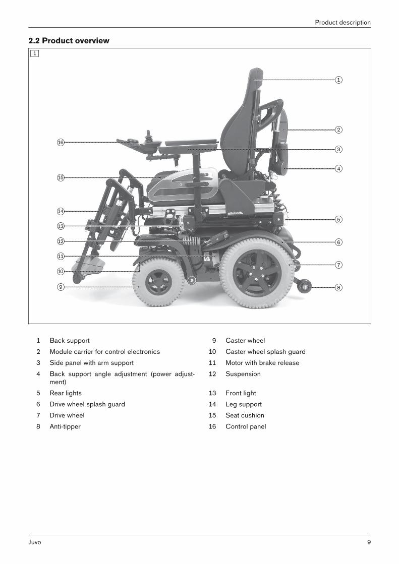
2.2 Product overview1
1 Back support 9 Caster wheel2 Module carrier for control electronics 10 Caster wheel splash guard3 Side panel with arm support 11 Motor with brake release4 Back support angle adjustment (power adjust
ment)12 Suspension
5 Rear lights 13 Front light6 Drive wheel splash guard 14 Leg support7 Drive wheel 15 Seat cushion8 Anti-tipper 16 Control panel
9Juvo
Product description

2
1 Back support 9 Drive wheel2 Module carrier for control electronics 10 Anti-tipper3 Side panel with arm support 11 Motor with brake release4 Back support angle adjustment (power adjust
ment)12 Drive wheel splash guard
5 Rear lights 13 Front light6 Suspension 14 Leg support7 Caster wheel splash guard 15 Seat cushion8 Caster wheel 16 Control panel
10
Product description
Juvo

3
1 Back support 8 Caster wheels2 Module carrier for control electronics 9 Drive wheel3 Side panel with arm support 10 Motor with brake release4 Back support angle adjustment (power adjust
ment)11 Front light
5 Rear lights 12 Leg support6 Suspension 13 Seat cushion7 Drive wheel splash guard 14 Control panel
3 Safety3.1 Explanation of warning symbols
WARNING Warning regarding possible serious risks of accident or injury.CAUTION Warning regarding possible risks of accident or injury.
NOTICE Warning regarding possible technical damage.
11Juvo
Safety

3.2 General safety instructionsHazards due to improper use of the product
WARNINGImproper product operationFalling, tipping over, collision due to user error► The product may only be used by a qualified user.► As a user or attendant, you must be trained in the use of the product by qualified personnel instructed by the
manufacturer.► Read the entire instructions for use.► The product may not be used in case of exhaustion or under the influence of alcohol, medications or drugs.► The product may not be used by users who have any mental limitations which can temporarily or permanently
limit attentiveness and judgement.► You must observe road traffic regulations when driving in road traffic.
WARNINGImpermissible useRisk of pinching, crushing, being pulled in, tipping, falling due to improper handling► Only use this product for its original intended purpose.► Only one person may be transported with the product at any one time.
WARNINGOverloadingSevere injuries if the product tips over due to overloading, damage to the product► Do not exceed the maximum load capacity (see the nameplate and section "Technical data").► Please note that certain options and add-on components will reduce the remaining load capacity.
WARNINGExceeding the service life Serious injuries due to failure to observe the manufacturer's requirements► Using the product beyond the specified expected service life (see Page 111) leads to increased residual risk
and should only take place subject to the due diligence and deliberations of qualified personnel.► If the service life is reached, the user or a responsible attendant should contact the qualified personnel who
fitted the product or the manufacturer's servicing department (see inside rear cover or back page foraddress). Here the user can obtain information about known risks and the current options for refurbishing theproduct.
CAUTIONExtreme temperaturesHypothermia or burns through contact with components, failure of components► Do not expose the product to any extreme temperatures (e.g. direct sunlight, sauna, extreme cold).
NOTICEUse under incorrect environmental conditions Damage to the product due to excessively high or low temperatures► Only use the product within a temperature range of -15 °C to +40 °C (5 °F to +104 °F).
12
Safety
Juvo

3.3 Effects of electromagnetic interference on the product and on the user
CAUTIONUse of mobile devices with electromagnetic emissions (e.g., mobile phones)Falling, collision with persons or objects due to interference with the control signals► Turn all mobile devices off while driving, since the driving characteristics of the product are affected by elec
tromagnetic fields.► Turn the control unit off when it is not required, since the product may generate electromagnetic fields that
can cause interference with other devices. The product has been tested according to EMC regulations.► Notwithstanding compliance with all applicable EMC directives and standards, the product can be affected by
interference from other electric devices (e.g., department store EAS systems) or cause interference with suchdevices. If this occurs, move your product outside the interference range.
• Powered wheelchairs may be susceptible to electromagnetic interference (EMI), which is interfering electromagnetic energy (EM) emitted from sources such as radio stations, TV stations, amateur radio (HAM) transmitters, two-way radios, and cellular phones.
• The interference (from radio wave sources) can cause the powered wheelchair to release its brakes, move byitself, or move in unintended directions.
• It can also permanently damage the powered wheelchairs control system.• Because EM energy rapidly becomes more intense as one move closer to the transmitting antenna (source),
the EM fields from hand-held radio wave sources (transceivers) are of special concern. It is possible to unintentionally bring high levels of EM energy very close to the powered wheelchair's control system while using thesedevices. This can affect powered wheelchair movement and braking.
• Other types of hand-held devices, such as cordless phones, laptop computers, AM/FM radios, TV sets, CDplayers, and cassette players, and small appliances, such as electric shavers and hair dryers, so far as weknow, are not likely to cause EMI problems to your powered wheelchair.
13Juvo
Safety

3.4 Nameplate and warning labels3.4.1 Signage on the productThe warning signs and nameplates are attached at the following mounting points to the power wheelchair:
4
5
14
Safety
Juvo

3.4.2 NameplateLabel Meaning
A Product; product reference numberB Read the instructions for use before using the product.
Observe safety information in the instructions for use.C Symbol for separate collection of electrical and electronic
devices. Components of the power wheelchair and batteriesmay not be disposed of in household waste.
D European article number (EAN)E Product version*F Serial number**G Maximum load capacity (see section "Technical data")H Maximum climbing ability (see section "Technical data")I Maximum speed (see section "Technical data")J Allowable axle load, frontK Allowable axle load, rearL Maximum gross weightM Manufacturer information/addressN CE marking – product safety in accordance with EU directives
The nameplates are found on the mobilitybase.
O Manufacturing date**** NN = country code; VV = country-specific version; C = configuration** S = speed code; YY = year of manufacture; WW = week of manufacture; PP = production site; XXX = sequentialproduction number*** YYYY = year of manufacture; MM = month of manufacture; DD = day of manufacture
Label MeaningA Product; product reference numberB Read the instructions for use before using the product.
Observe safety information in the instructions for useC Symbol for separate collection of electric and electronic
devices. Components of the power wheelchair and batteriesmay not be disposed of in household waste.
D European article number (EAN)E Product version*F Serial number**G Maximum load (see section "Technical data")H Maximum climbing ability (see section "Technical data")I Maximum speed (see section "Technical data")J Allowable axle load, frontK Allowable axle load, middleL Allowable axle load, rearM Maximum gross weightN Manufacturer information/addressO CE marking – product safety in accordance with EU directives
The nameplates are found on the mobilitybase.
P Manufacturing date**** NN = country code; VV = country-specific version; C = configuration** S = speed code; YY = year of manufacture; WW = week of manufacture; PP = production site; XXX = sequentialproduction number*** YYYY = year of manufacture; MM = month of manufacture; DD = day of manufacture
If the adjacent symbol appears on the nameplate, this indicates the following:The product may not be used as a seat in vehicles for transporting persons with reduced mobility.
15Juvo
Safety

3.4.3 Warning labelsLabel Meaning
A Power driving mode: motor brake locked (see Page 50)B Manual driving mode: motor brake released (see Page 50)
A Caster wheel swivel lock: the caster wheels are unlocked andcan swivel freely (when ordered)
B Caster wheel swivel lock: the caster wheels are locked for driving straight ahead (when ordered)
Risk of pinching. Do not reach into the danger area.
Label MeaningA Power driving mode: motor brake locked (see Page 50)B Manual driving mode: motor brake released (see Page 50)
Risk of pinching. Do not reach into the danger area.
Label Meaning(Only in case of installation of ISO sets according to ISO7176-19)Fixation point/eyebolt to attach the product in vehicles for transporting persons with reduced mobility
4 Delivery4.1 Scope of deliveryThe power wheelchair is normally shipped fully assembled and fitted to the personal requirements of the respectiveuser.The scope of delivery includes:• Fitted power wheelchair with main components• Options depending on equipment• Battery charger• Instructions for use (user)
4.2 AccessoriesThe standard model can be fitted to the user's personal requirements thanks to a large range of options. A full list of the available modules and accessories is shown on the order form and in the accessories catalogue. For use of the options, see the section "Use".Please note that retrofitting options further reduces the maximum load capacity (user weight + luggage).
16
Delivery
Juvo

The maximum load capacity (see print on the nameplate; see Page 15) is thereby respectively reduced by theweight of the retrofitted options.
4.2.1 Accessories from other manufacturersAs per the order for the power wheelchair, some components from third-party manufacturers have been installedprior to delivery. Please observe the following instructions in this regard:• Accessories from other manufacturers must be intended for use on wheelchairs and must fulfil all currently
applicable legal requirements under the Medical Devices Act as well as further applicable standards.• When using the accessories from other manufacturers, the instructions for use / manufacturer's instructions for
the relevant accessories must be strictly observed. These are included with the instructions for use.• Ottobock assumes no liability for combinations with medical devices and/or accessories from other manufac
turers not included in Ottobock's modular system.• In case of questions or problems with accessories from other manufacturers, please contact the qualified per
sonnel who adjusted this product.
4.3 Storage4.3.1 Storage during daily useThe power wheelchair should always be protected against external influences. The control unit must be turned off.
4.3.2 Storage during extended disuse
NOTICEDeep dischargeBattery damage due to standby current► Deactivate the circuit breaker if the wheelchair is not used for more than 3 days. ► To deactivate the circuit breaker: see Page 19
Please observe the following if the power wheelchair is not used for more than 3 days:
Storage conditions• Maintain an ambient temperature between -15 °C and +40 °C (5 °F and +104 °F) and relative humidity
between 45 % and 85 %.• Store the power wheelchair in a dry, enclosed room with sufficient air circulation and protection from external
influences.• Protect the wheels against ground frost, e.g. by relieving them completely through assembly blocks or wooden
boards.• Maintain sufficient clearance from sources of heat. If the product is parked for an extended period of time or
the tyres overheat (e.g. in the vicinity of radiators or in case of exposure to strong sunlight behind glass), thetyres may become permanently deformed.
• Fill pneumatic tyres with slight overpressure.• Rotate the wheels weekly to prevent flat tyres from extended standing.• For extended storage, store the power wheelchair so the wheels are not in contact with the ground.
Note regarding the tyres• If the power wheelchair is not moved for several days, permanent colour changes may occur where the wheel
chair comes into contact with the surface it is standing on. Therefore a suitable mat should be used when parking it for extended periods of time.
• Tyres contain chemical substances that can react with other chemical substances (such as cleaning agents,acids, etc.).
• Black tyres contain soot particles. They may leave black marks where they come into contact with the ground.Therefore the manufacturer recommends grey tyres if the wheelchair is primarily used indoors.
• Avoid unnecessary parking outdoors. Direct exposure to sunlight/UV radiation causes the tyres to age morequickly. As a result, the tread surface hardens and corner pieces break out of the tread.
• The tyres must be changed when the tread is less than 1 mm (0.04") to ensure safe driving behaviour.• The tyres should be replaced every 2 years regardless of wear and tear.• When power wheelchairs with PU tyres are parked for long periods, the tyres may become deformed (flat
spots). This deformation will go away on its own over time while driving.
17Juvo
Delivery

5 Preparation for use5.1 Safety instructions
WARNINGImproper handling of packaging materialsRisk of suffocation due to neglect of the duty to supervise► Packaging materials must be kept out of the reach of children.
WARNINGUncontrolled movement of components when making adjustmentsCrushing, pinching, blows due to non-observance of the maintenance and repair instructions► Ensure that body parts, such as hands or head, are never in the danger zone.► Perform the work with the aid of a helper for support.
WARNINGIndependent modification of settingsSerious injuries to the user due to unallowable changes to the product► Do not modify the settings established by the qualified personnel. ► In case of problems with the settings (unsatisfactory seating position, caster wheel wobble, etc.) please con
tact the qualified personnel who adjusted your product.
CAUTIONScrew connections not tightenedPinching, crushing, tipping over, falling of user due to assembly errors► After all adjusting/readjusting work authorised by the manufacturer, retighten the mounting screws/nuts firmly.
Observe any torque settings which may be specified.
5.2 Initial operationThe specialist dealer ships the power wheelchair fully assembled and ready to use.The following additional tasks may be required:• Activating the circuit breaker (see Page 19)• Folding up the backrest (see Page 23)• Charging the battery (see Page 53)
5.3 SettingsThe user may only perform the fine-tuning adjustments described in the following.This fine-tuning should be carried out by attendants and only in the presence of the user. The user should situpright in the power wheelchair while adjustments are made.• Adjusting the back angle (see Page 24)• Adjusting the armrests (see Page 20)• Adjusting the position of the control panel (see Page 21)• Adjusting the lower leg length (see Page 22)• Adjusting the lap belt (see Page 68)• Adjusting the belt lengths (see Page 88)Further adjustments may be made only by qualified personnelAll parts of the product should be cleaned thoroughly before adjustments are made.
5.3.1 Changing control unit parameters
WARNINGIncorrect configuration settingsFalling, tipping over, collision due to programming errors► Programming may only be performed by qualified personnel trained by the manufacturer. The manufacturer of
the product and the control unit manufacturer are not liable in case of damage caused by programming whichwas not performed properly and/or which was not adjusted properly according to the user's abilities.
18
Preparation for use
Juvo

If necessary, the qualified personnel can adapt the preprogrammed wheelchair control unit and options to the concrete requirements of the user.
6 Use6.1 Circuit breaker
INFORMATION► Should the automatic circuit breaker deactivate repeatedly after activation for no discernible reason, contact
the qualified personnel.► For shipping or when the power wheelchair is not being used for an extended period of time, the automatic
circuit breaker should be deactivated.
The automatic circuit breaker has to be activated before the power wheelchair can be switched on.It is located under the seat between the drive wheels.
6 Activating the circuit breaker► Close the reset lever, which is at an angle (see
fig. 6, item 1). → The reset lever engages and the circuit breaker is
activated.Deactivating the circuit breaker► Press the pushbutton until the reset lever flips up at
an angle (see fig. 6, item 2). → The circuit breaker is deactivated.
6.2 Side panelsThe side panels protect the user and his/her clothing from getting dirty. The installed armrests offer the user additional support for the forearms.
6.2.1 Removing/installing the side panelsTo make getting in from the side easier or for transportation, the side panels can be removed if needed.
7 Removing the side panel1) Loosen the thumb screw on the side panel holder
(see fig. 7, item 1).2) Pull the side panel out from the side panel holder
and set it aside (see fig. 7, item 2).3) Only for side panel with control panel:
→ Turn the control device off (see Page 25).→ Carefully let the side panel with the control pan
el hang down while getting in. → For transporting the power wheelchair, place
the side panel on the seat.Installing the side panel1) Insert the side panel into the side panel holder.2) Re-tighten the thumb screw on the side panel hold
er (see fig. 7, item 1).
To make getting in from the side easier or for transportation, the side panels can be removed if needed.
19Juvo
Use

8 Removing the side panel1) Loosen the thumb screw on the side panel holder
(see fig. 8, item 1).2) Pull the side panel out from the side panel holder
and set it aside (see fig. 8, item 2).3) Only for side panel with control panel:
→ Turn the control unit off (see Page 25).→ Carefully let the side panel with the control pan
el hang down while getting in. → For transporting the power wheelchair, place
the side panel on the seat.Installing the side panel1) Insert the side panel into the side panel holder.2) Re-tighten the thumb screw on the side panel hold
er (see fig. 8, item 1).
To make getting in from the side easier or for transportation, the side panels can be removed if needed.
9 Removing the side panel1) Loosen the thumb screw on the side panel holder
(see fig. 9, item 1).2) Pull the side panel out from the side panel holder
and set it aside.3) Only for side panel with control panel:
→ Turn the control unit off (see Page 25).→ Carefully let the side panel with the control pan
el hang down while getting in. → For transporting the power wheelchair, place
the side panel on the seat.Installing the side panel1) Insert the side panel into the side panel holder.2) Re-tighten the thumb screw on the side panel hold
er (see fig. 9, item 1).
6.2.2 Adjusting the side panelsThe height of the armrests, the forearm length and the clothing protector can be subsequently adapted.The height of the armrests, the forearm length and the depth position of the side panel can be subsequently adapted.
10 Adjusting the armrest height1) Loosen the Allen head screw on the side panel
mounting (see fig. 10, item 1).2) Slide the armrests up or down to the desired posi
tion.3) Re-tighten the Allen head screw.Adjusting the armrest to the forearm length1) Loosen the 2 Allen head screws on the underside of
the armrest (see fig. 10, item 2).2) Push the armrest to the front or back into the
desired position.3) Tighten the 2 Allen head screws.
20
Use
Juvo

11 Adjusting the side panel depth1) Loosen the 2 Allen head screws on the side panel
mounting (see fig. 11, item 1).2) Slide the side panels on the seat profiles as needed
(see fig. 11, item 2).3) Firmly re-tighten the 2 Allen head screws to 6 Nm.
6.2.3 Adjusting the control panel position
INFORMATIONBy default, the control panel is mounted on the side specified in the order. It can also be mounted on the otherside of the power wheelchair later on if the user so desires. Please contact the qualified personnel who deliveredthe product to you.
The depth and height of the control panel position is subsequently adjustable.
12 Adjusting the depth of the control panel position1) Loosen the set screws on the bottom of the armrest
(see fig. 12, item 1).2) Slide the rail with the control panel forwards or
backwards.INFORMATION: If the control panel rail is toolong it can be shortened. Please contact thequalified personnel who adjusted your product.
3) Tighten the set screws on the bottom of the armrest.
13 Adjusting the depth of the control panel position1) Loosen the set screws on the bottom of the armrest
(see fig. 13, item 1).2) Slide the rail with the control panel forwards or
backwards.INFORMATION: If the control panel rail is toolong it can be shortened. Please contact thequalified personnel who adjusted your product.
3) Tighten the set screws on the bottom of the armrest.
Adjusting the height of the control panel position1) Loosen the set screw on the height adjustment (see
fig. 13, item 2).2) Adjust the height.3) Tighten the set screw on the height adjustment.
21Juvo
Use

6.3 LegrestsINFORMATION
► Please note that Ottobock has delivered this power wheelchair without legrests as per the order.► Prior to using the legrests from another manufacturer, please read and observe the instructions for use / man
ufacturer's instructions from the other manufacturer. These are included with the instructions for use.► In case of questions or problems with these accessories, please contact the qualified personnel who adjusted
this product.► Ottobock assumes no liability for combinations with accessories from other manufacturers not included in
Ottobock's modular system.
The legrests support the user's feet. The height of the legrests has been adjusted by qualified personnel to the length of the user's lower leg. The angle of the footrest has been set by the qualified personnel so that it allows the ankles to rest in a comfortableposition.
6.3.1 Removing/installing the legrests
CAUTIONIncorrect handling when getting inCrushing, pinching, impacts due to incorrect handling ► Do not reach into the danger area with your fingers when folding the legrest or footplates up or down.► Never step on the footplates when getting in and out.► Note projecting edges.
INFORMATIONFor detaching/attaching the power legrests: see Page 65.
To make getting in easier or for transportation, the legrests can be removed if needed.
14 Removing the legrests1) Fold up the footplate.2) Push the legrest locking mechanism back and
down (see fig. 14, item 1).3) Swing out the legrest (see fig. 14, item 2).4) Pull the legrest up and remove it (see fig. 14,
item 3).Installing the legrests1) Engage the legrest in the holder straight from above
(see fig. 14, item 3).2) Push the legrest to the inside (see fig. 14, item 2)
until the locking mechanism engages (see fig. 14,item 1).
3) Fold down the footplate.
6.3.2 Adjusting the legrests
CAUTIONExposed pinch pointsCrushing, pinching due to incorrect handling ► Do not reach into the danger area with your fingers when folding the legrest or footplates up or down.
The legrests can be subsequently adjusted to the user's lower leg length.
22
Use
Juvo
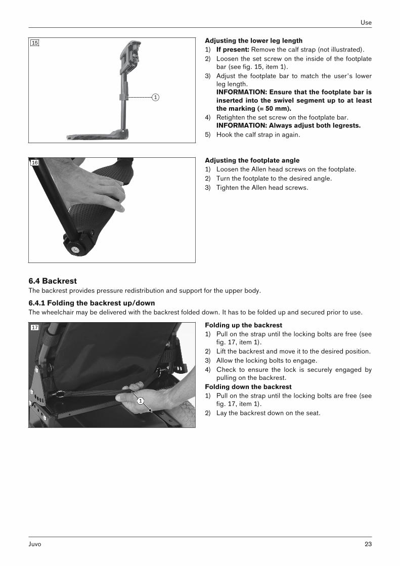
15 Adjusting the lower leg length1) If present: Remove the calf strap (not illustrated).2) Loosen the set screw on the inside of the footplate
bar (see fig. 15, item 1).3) Adjust the footplate bar to match the user's lower
leg length.INFORMATION: Ensure that the footplate bar isinserted into the swivel segment up to at leastthe marking (= 50 mm).
4) Retighten the set screw on the footplate bar.INFORMATION: Always adjust both legrests.
5) Hook the calf strap in again.
16 Adjusting the footplate angle1) Loosen the Allen head screws on the footplate.2) Turn the footplate to the desired angle.3) Tighten the Allen head screws.
6.4 BackrestThe backrest provides pressure redistribution and support for the upper body.
6.4.1 Folding the backrest up/downThe wheelchair may be delivered with the backrest folded down. It has to be folded up and secured prior to use.
17 Folding up the backrest1) Pull on the strap until the locking bolts are free (see
fig. 17, item 1).2) Lift the backrest and move it to the desired position.3) Allow the locking bolts to engage.4) Check to ensure the lock is securely engaged by
pulling on the backrest.Folding down the backrest1) Pull on the strap until the locking bolts are free (see
fig. 17, item 1).2) Lay the backrest down on the seat.
23Juvo
Use

18 Folding up the backrest1) If needed: Remove the side panels.2) Fold the backrest up.3) Insert the cotter pin (see fig. 18, item 1).4) Lock the cotter pin (see fig. 18, item 2).5) Check to ensure the lock is securely engaged by
pulling on the backrest.6) If needed: Reinstall the side panels.Folding down the backrest1) If needed: Remove the side panels.2) Unlock the cotter pin (see fig. 18, item 2).3) Pull out the cotter pin (see fig. 18, item 1).4) Lay the backrest down on the seat. 5) If needed: Reinstall the side panels.
6.4.2 Adjusting the Back AngleThe back angle can be adapted to the particular needs of the user.
Adjusting the back angle using the strap1) Pull on the strap until the locking bolts are free (see fig. 17, item 1).2) Move the backrest to the desired position.3) Allow the locking bolts to engage.4) Check to ensure the lock is securely engaged.
Power back angle adjustmentThe back angle is adjusted as needed by using this seat function (see Page 64).
Recaro® seatThe back angle is adjusted using a knob (see Page 59).
6.5 Getting in and transferring
CAUTIONIncorrect handling when getting inFalling, tipping over due to incorrect handling► Turn the control unit off while getting in and out, in order to avoid accidental driving.► Always place the seat in a horizontal position.► Note that the armrests are not capable of bearing full body weight, and therefore must not be used for getting
into or out of the wheelchair.► Always put on a lap belt when driving.
CAUTIONIncorrect handling when getting inCrushing, pinching, impacts due to incorrect handling ► Do not reach into the danger area with your fingers when folding the legrest or footplates up or down.► Never step on the footplates when getting in and out.► Note projecting edges.
The modular design of the power wheelchair and the ease with which you can remove the side panels and legrestsmake it easy to get into and out of the wheelchair from the side or from the front. Users can choose the method for getting into and out of the wheelchair which is most suitable for them.
24
Use
Juvo

19 Getting in from the front1) Turn the control device off.2) Fold up the foot supports (see fig. 19) or remove
the leg supports (see Page 22). 3) Have an attendant assist you or use a transfer lifter
to get into and out of the power wheelchair.4) Install the leg supports. Fold down the foot sup
ports.Getting in from the side (alternative option)1) Turn the control device off.2) Remove or fold up the side panel (see Page 19).3) If needed: Remove the corresponding leg support.4) Get into or out of the power wheelchair from the
side. A ramp makes this easier.5) Reinstall the leg support and side panel and fold
down the foot support.
20 Getting in from the front1) Turn the control device off.2) Fold up the foot supports (see fig. 20) or remove
the leg supports (see Page 22). 3) Have an attendant assist you or use a transfer lifter
to get into and out of the power wheelchair.4) Install the leg supports. Fold down the foot sup
ports.Getting in from the side (alternative option)1) Turn the control device off.2) Remove or fold up the side panel (see Page 19).3) If needed: Remove the corresponding leg support.4) Get into or out of the power wheelchair from the
side. A ramp makes this easier.5) Reinstall the leg support and side panel and fold
down the foot support.
6.6 Control unit6.6.1 VR2 control unit
CAUTIONRisk of uncontrolled driving behaviour Falling, tipping, collision with persons or nearby objects due to interference from electromagnetic fields► Switch all mobile devices off while driving.► Turn the control unit off when it is not needed.
The power wheelchair is controlled by a VR2 control unit. Because the control unit is programmable, it can be adapted to the personal requirements of the user; e.g. thespeed, acceleration and deceleration values can all be adapted.
6.6.1.1 Control panelThe power wheelchair is operated using the control panel. The control panel is divided into the keypad, two LED displays and the joystick. The charging/programming receptacle is on the underside.The control panel is used to switch the power wheelchair on and off, enter driving commands and display the current status of certain functions and components.
25Juvo
Use

1 Joystick2 [Decrease speed] button3 [Increase speed] button4 [Selected speed level] LED display5 [Horn] button6 [On/off] button7 [Charge level] LED display
21
8 Charging/programming receptacle
6.6.1.1.1 Buttons and display functions
JoystickThe speed and driving direction are controlled with the joystick (see Page 46).
[On/off] buttonPressing this button turns the power wheelchair on or off (see Page 45). In combination with additional operatingsteps, it also activates/deactivates the drive-away lock (see Page 48).
[Decrease speed] and [Increase speed] buttonsPressing the button briefly increases/decreases the speed level (see Page 46). The acoustic signal changes whenthe maximum speed level is reached.
[Horn] buttonThe horn will sound as long as the button is pressed.
[Selected speed level] LED displayThe LED display shows the currently selected speed level (1–5).
[Charge level] LED displayThe [Charge level] LCD screen is divided into 10 segments and shows the current charge level:• After brief operation, the battery indicator shows the exact battery status.• A charge of 100% corresponds to 10 segments on the battery symbol. • As the remaining battery charge decreases, the LED segments turn off one by one.• If only one segment of the LED display is flashing, then the battery is in an undervoltage state. The battery must
be charged immediately.• If all 10 LED segments are flashing, this means that the battery is in an overvoltage state. Please continue to
drive at low speed only.• The charging process is indicated by sequential flashing of the LEDs. The driving function is blocked when the
battery is charging.
Battery indicator on the control panel
Display InformationBattery is charged
Charge battery if possible
Sequential indicator
Battery is charging
26
Use
Juvo

Display Information
Flashing light
Battery undervoltage, battery charging urgently required
Flashing light
Battery overvoltage
Further LED display functionsFurther LED display symbols are described in the following sections:• See section "Usage" > "Drive-away lock" (see Page 48)• See section "Maintenance/repair" > "Troubleshooting" (see Page 104)
6.6.1.2 Control panelThe power wheelchair is operated using the control panel. The control panel is divided into the keypad, two LED displays and the joystick. The charging/programming receptacle is on the underside.The control panel is used to switch the power wheelchair on and off, enter driving commands and display the current status of certain functions and components.
1 Joystick2 [Direction indicator left/right] button3 [Select additional power function] button
3a: [Seat function 1] LED display3b: [Seat function 2] LED display
4 [Decrease speed] button5 [Increase speed] button6 [Selected speed level] LED display7 [Warning flasher on/off] button8 [Horn] button9 [Lights on/off] button
10 [On/off] button11 [Charge level] LED display
22
-- Charging/programming receptacle (on the back)
6.6.1.2.1 Buttons and display functions
JoystickThe speed and driving direction are controlled with the joystick (see Page 46). When a power seat option is activated, the joystick adjusts this seat option (see Page 66).
[On/off] buttonPressing this button turns the power wheelchair on or off (see Page 45). In combination with additional operatingsteps, it also activates/deactivates the drive-away lock (see Page 48).
[Decrease speed] and [Increase speed] buttonsPressing the button briefly increases/decreases the speed level (see Page 46). The acoustic signal changes whenthe maximum speed level is reached.
[Select additional power functions] buttonPressing this button toggles through seat function 1 – seat function 2 – no seat function. The selected seat functionis indicated by the LEDs.
27Juvo
Use

[Seat function 1/2] LED displayThis LED display shows the currently active additional power function.
[Horn] buttonThe horn will sound as long as the button is pressed.
[Warning flasher on/off] buttonAll 4 warning flashers are activated/deactivated when this button is pressed.If the wheelchair is not fitted with lights for road traffic, this button is deactivated (no function).
[Lights on/off] buttonThe front and rear lights are activated/deactivated by pressing this button.If the wheelchair is not fitted with lights for road traffic, this button is deactivated (no function).
[Direction indicator right] and [Direction indicator left] buttonsPressing these buttons activates/deactivates the respective front and rear direction indicators.If the wheelchair is not fitted with lights for road traffic, this button is deactivated (no function).
[Selected speed level] LED displayThe LED display shows the currently selected speed level (1–5).
[Charge level] LED displayThe [Charge level] LCD screen is divided into 10 segments and shows the current charge level:• After brief operation, the battery indicator shows the exact battery status.• A charge of 100% corresponds to 10 segments on the battery symbol. • As the remaining battery charge decreases, the LED segments turn off one by one.• If only one segment of the LED display is flashing, then the battery is in an undervoltage state. The battery must
be charged immediately.• If all 10 LED segments are flashing, this means that the battery is in an overvoltage state. Please continue to
drive at low speed only.• The charging process is indicated by sequential flashing of the LEDs. The driving function is blocked when the
battery is charging.
Battery indicator on the control panel
Display InformationBattery is charged
Charge battery if possible
Sequential indicator
Battery is charging
Flashing light
Battery undervoltage, battery charging urgently required
Flashing light
Battery overvoltage
Further LED display functionsFurther LED display symbols are described in the following sections:
28
Use
Juvo

• Section "Drive-away lock" (see Page 48)• Section "Power seat functions" (see Page 61)• Section "Troubleshooting" (see Page 104)
6.6.2 R-Net control unit
CAUTIONRisk of uncontrolled driving behaviour Falling, tipping, collision with persons or nearby objects due to interference from electromagnetic fields► Switch all mobile devices off while driving.► Turn the control unit off when it is not needed.
The power wheelchair is controlled by an R-Net control device in combination with the TEN° control panel.Because the control unit is programmable, it can be adapted to the personal requirements of the user; e.g. thespeed, acceleration and deceleration values can all be adapted.A separate LCD monitor is also installed (see Page 71).
6.6.2.1 TEN° control panelThe power wheelchair is operated using the control panel. The control panel consists of a button section, LCD screen and joystick. The charging receptacle and two inputsfor external buttons are located on the underside.The control panel is used to switch the power wheelchair on and off, enter driving commands and display the current status of certain functions and components.
Front side – TEN° control panel
1 Joystick2 [Direction indicator left – on/off] button
[Direction indicator right – on/off] button3 [On/off] button4 [Lights on/off] button5 LCD screen6 [Warning flashers on/off] button7 [Profile/mode] button8 [Horn] button9 Rotary multi-selector
right: [Increase speed];left: [Decrease speed]
23
Back side – TEN° control panel
1 Transmitter for infrared signals2 Charging receptacle3 Connection for external [Profile] or [Pro
file/mode] button (programmable)4 Connection for external [on/off] button
24
29Juvo
Use
6.6.2.2 Buttons and display functions
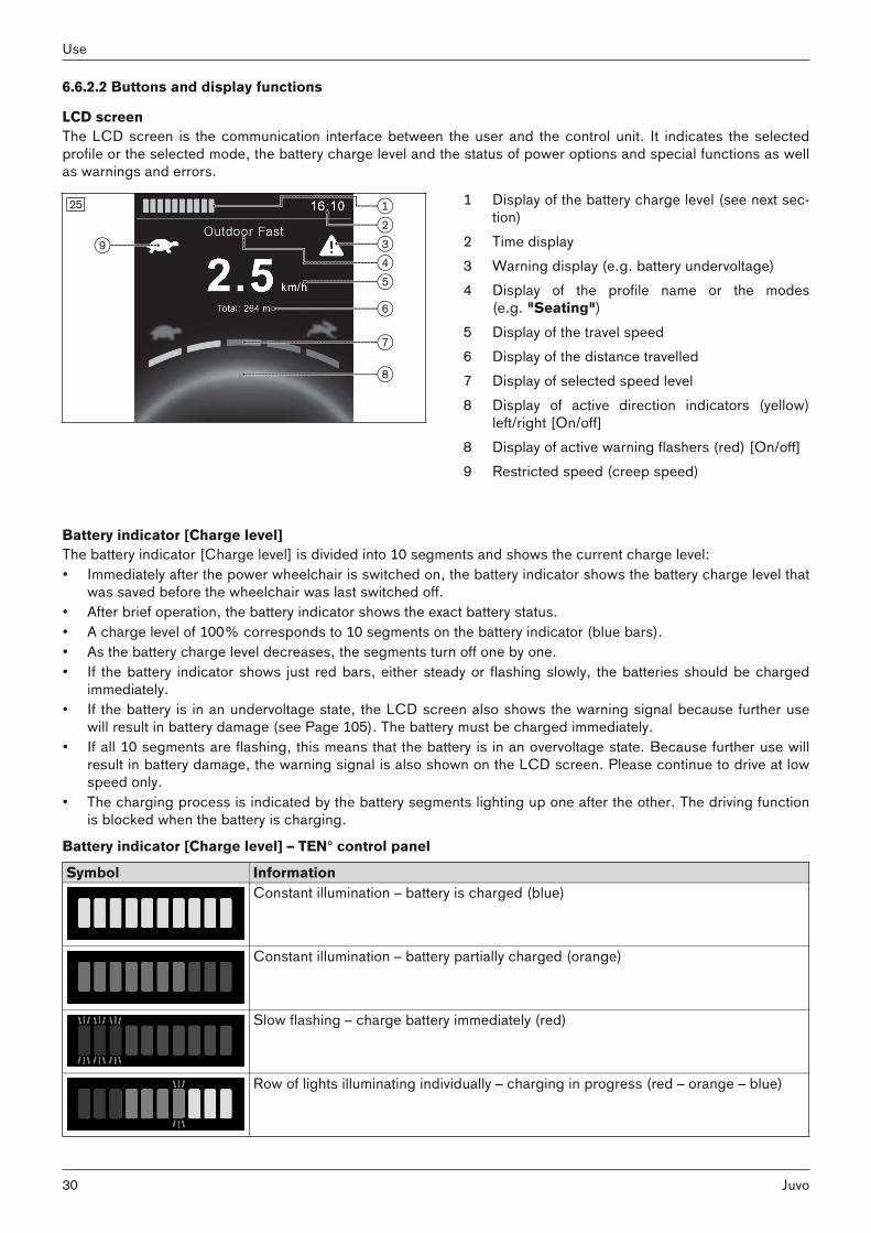
LCD screenThe LCD screen is the communication interface between the user and the control unit. It indicates the selectedprofile or the selected mode, the battery charge level and the status of power options and special functions as wellas warnings and errors.
1 Display of the battery charge level (see next section)
2 Time display3 Warning display (e.g. battery undervoltage)4 Display of the profile name or the modes
(e.g. "Seating")5 Display of the travel speed6 Display of the distance travelled7 Display of selected speed level8 Display of active direction indicators (yellow)
left/right [On/off]8 Display of active warning flashers (red) [On/off]9 Restricted speed (creep speed)
25
Battery indicator [Charge level]The battery indicator [Charge level] is divided into 10 segments and shows the current charge level:• Immediately after the power wheelchair is switched on, the battery indicator shows the battery charge level that
was saved before the wheelchair was last switched off. • After brief operation, the battery indicator shows the exact battery status.• A charge level of 100% corresponds to 10 segments on the battery indicator (blue bars). • As the battery charge level decreases, the segments turn off one by one.• If the battery indicator shows just red bars, either steady or flashing slowly, the batteries should be charged
immediately.• If the battery is in an undervoltage state, the LCD screen also shows the warning signal because further use
will result in battery damage (see Page 105). The battery must be charged immediately.• If all 10 segments are flashing, this means that the battery is in an overvoltage state. Because further use will
result in battery damage, the warning signal is also shown on the LCD screen. Please continue to drive at lowspeed only.
• The charging process is indicated by the battery segments lighting up one after the other. The driving functionis blocked when the battery is charging.
Battery indicator [Charge level] – TEN° control panel
Symbol InformationConstant illumination – battery is charged (blue)
Constant illumination – battery partially charged (orange)
Slow flashing – charge battery immediately (red)
Row of lights illuminating individually – charging in progress (red – orange – blue)
30
Use
Juvo

JoystickThe speed and driving direction in a driving profile (e.g. "Drive") are controlled with the joystick (see Page 46). If the control unit is in "Seating" mode, the seat option can be adjusted by moving the joystick forwards/backwards(see Page 66) or switched to the next seat option by moving it left/right. You can navigate within the operating modes (e.g. "Bluetooth Devices" mode) by moving the joystick forwards/backwards or right/left.
[Direction indicator left – on/off] button; [Direction indicator right – on/off] buttonPressing these buttons activates/deactivates the respective front and rear direction indicators.If the power wheelchair is not fitted with lights for road traffic, this button is deactivated (no function).
[On/off] buttonPressing this button turns the power wheelchair on or off (see Page 45). In combination with additional operatingsteps, it also activates/deactivates the drive-away lock (see Page 48).
[Lights on/off] buttonThe front and rear lights are activated/deactivated by pressing this button.If the power wheelchair is not fitted with lights for road traffic, this button is deactivated (no function).
[Warning flashers on/off] buttonAll 4 warning flashers are activated or deactivated when this button is pressed.If the power wheelchair is not fitted with lights for road traffic, this button is deactivated (no function).
[Profile/mode] buttonPressing this button retrieves the available driving profiles and operating modes of the control system in succession (dependent on programming and connected devices). The system first switches from one driving profile to the next driving profile (e.g. "Drive"; "Speciality Control"; ...;"No Assist"; "Attendant"). The number of driving profiles is dependent on programming. After reaching the lastdriving profile, you can switch to the operating modes by pressing the button again.The programmed operating modes are now toggled through ("Seating"; "Bluetooth Devices"; "IR Menu"; "I/OModule"). The number of operating modes is dependent on programming. The joystick is used to navigate withinthe operating modes (see above). After reaching the last mode, you can switch back to the first driving profile,"Drive", by pressing the button again.
LCD display for profiles (selection) – TEN° control panel
Display Information"Drive" profileStandard driving profile for the TEN° control panel. Among other things, the numberof speed levels and the acceleration values are defined here.If there are special requirements for use, other driving profiles can be saved in thecontrol unit.
"No Assist" profileThe driving profile is only enabled for control units with an electronic track stabiliser(gyro). For safety reasons, the user must activate this profile when travelling inmeans of transportation as the electronic track stabiliser is disrupted by the movement of means of transportation (bus; train; ship).
"Attendant" profileThis profile enables operation of an attendant control. The profile image appearsautomatically on the LCD screen when the attendant control is activated by theattendant.
31Juvo
Use

Display Information"Specialty Control" profileThis profile enables operation of a special control (e.g. chin control, sip and puffcontrol). The profile image appears automatically on the LCD screen when the special control is activated.
LCD display for operating modes – TEN° control panel
Display Information"Seating" modeThis mode enables operation of the power seat functions delivered with the powerwheelchair. Further information: see Page 66 ff.
"Bluetooth Devices" modeThis mode enables control of PCs and smartphones/tablets with a Bluetooth function. Mouse functions are operated via joystick movements.The devices being controlled must be synchronised with the control unit prior to use.Further information: see Page 36 ff.
"IR Menu" modeThis mode enables control of devices with infrared remote control – e.g. TV, DVDplayers, projectors, etc. The devices being controlled must be synchronised with the control unit prior to use.Synchronisation is performed by the qualified personnel.Further information: see Page 40 ff."I/O Module 1" mode – option (designation can be individually adjusted bythe qualified personnel)The mode enables wireless control of up to 6 receivers for building services – e.g.power outlets, light switches, blinds, etc.The devices being controlled must be synchronised with the control unit prior to use.Synchronisation is performed by the qualified personnel.The mode alternatively enables use of a push-button module.The mode is only displayed when the option has been ordered.Further information: see Page 85 ff.
Important LCD symbols – TEN° control panel
Display InformationStart-up screen when switching on
Restricted speed (creep speed)Turtle symbol lights up yellow: automatic speed reduction (e.g. because a seatfunction was activated)
Restricted speed (creep speed)Turtle symbol flashes red: power wheelchair is prevented from driving
Temperature warningThermometer symbol lights up orange: e.g. overheating due to excessive load
32
Use
Juvo
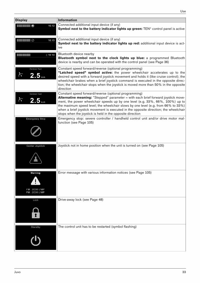
Display InformationConnected additional input device (if any)Symbol next to the battery indicator lights up green: TEN° control panel is active
Connected additional input device (if any)Symbol next to the battery indicator lights up red: additional input device is active
Bluetooth device nearbyBluetooth symbol next to the clock lights up blue: a programmed Bluetoothdevice is nearby and can be operated with the control panel (see Page 36)
Constant speed forward/reverse (optional programming)"Latched speed" symbol active: the power wheelchair accelerates up to thedesired speed with a forward joystick movement and holds it (like cruise control); thewheelchair brakes when a brief joystick command is executed in the opposite direction; the wheelchair stops when the joystick is moved more than 50% in the oppositedirectionConstant speed forward/reverse (optional programming)Alternative meaning: "Stepped" parameter = with each brief forward joystick movement, the power wheelchair speeds up by one level (e.g. 33%, 66%, 100%) up tothe maximum speed level; the wheelchair slows by one level (e.g. from 66% to 33%)when a brief joystick movement is executed in the opposite direction; the wheelchairstops when the joystick is held in the opposite directionEmergency stop: severe controller / handheld control unit and/or drive motor malfunction (see Page 105)
Joystick not in home position when the unit is turned on (see Page 105)
Error message with various information notices (see Page 105)
Drive-away lock (see Page 48)
The control unit has to be restarted (symbol flashing)
33Juvo
Use

Display InformationSleep symbol (control unit shortly switches to sleep mode)
This symbol is displayed during configuration procedures Procedure successful
This symbol is displayed during configuration procedures Procedure unsuccessful
This symbol is displayed during configuration procedures Procedure running; please wait
"Stop button" in latched drive mode (cruise control); the wheelchair brakes when abrief joystick command is executed in the opposite direction; the wheelchair stopswhen the joystick is moved more than 50% in the opposite directionAlternative: display with special controls
[Horn] buttonThe horn will sound as long as the button is pressed.
Rotary multi-selector right: [Increase speed]Moving the rotary multi-selector to the right increases the speed level see Page 46. The acoustic signal changeswhen the maximum speed level is reached. Depending on the programming of the control system, additional symbols may be displayed when the rotary multi-selector is operated.
Rotary multi-selector left: [Decrease speed]Moving the rotary multi-selector to the left decreases the speed level see Page 46. The acoustic signal changeswhen the minimum speed level is reached. Depending on the programming of the control system, additional symbols may be displayed when the rotary multi-selector is operated.
LCD screenThe LCD screen is the communication interface between the user and the control unit. It indicates the selectedprofile or the selected mode, the battery charge level and the status of power options and special functions as wellas warnings and errors.
Further LCD display functionsFurther LCD display symbols are described in the following sections:• Section "Drive-away lock" (see Page 48)• Section "Power seat functions" (see Page 61)• Section "Troubleshooting" (see Page 104)
6.6.2.3 Adjustment possibilitiesThe user can change settings on the display:
34
Use
Juvo

26 • To retrieve the "Settings" menu, the [Warning flashers on/off] button must be pressed and held.
• To navigate through the menu, move the joystick upand down.
• The desired setting function (e.g. [Time]) is selected by moving the joystick to the right.
• Concrete settings (value changes) are made by further joystick movements up/down or right/left.
• Some settings are made by turning the rotary multi-selector to the left or right (see Page 42).
• To save, select the menu item [Exit] and move thejoystick to the right to confirm.
[Time] menu item >The following submenus are displayed by moving the joystick to the right.• [Set Time]: The displayed time can be changed with additional joystick movements here.• [Display Time]: By moving the joystick to the left/right, the time display format can be changed or the display
turned off. Adjustable options are [12hr], [24hr] or [Off].• [Exit]: Return to the Settings menu by moving the joystick to the right
[Distance] menu item >The following submenus are displayed by moving the joystick to the right.• [Total Distance]: Display of the overall distance travelled with the control unit.• [Trip Distance]: Display of the distance travelled since the last reset to zero.• [Display Distance]: Moving the joystick to the left/right determines whether the total distance or trip distance
appears on the display.• [Clear Trip Distance]: The trip distance can be erased by moving the joystick to the right.• [Exit]: Return to the Settings menu by moving the joystick to the right
[Backlight] menu item >The following submenus are displayed by moving the joystick to the right.• [Backlight]: The intensity of the LCD backlight can be adjusted by moving the joystick to the left/right. The
adjustable range is 0% to 100% in steps of 10%.• [Autobacklight]: The available options Off and On can be selected by moving the joystick to the left/right. If set
to On, the display adjusts the screen brightness based on the light sensor reading. If set to Off, the screenbrightness will not change with changes in light intensity.
• [Backlight Timeout]: Automatic dimming of the backlight after a defined time period can be set by moving thejoystick to the left/right. The setting is 0 to 240 seconds in increments of 5 seconds. A value of 0 seconds deactivates this function.
• [Exit]: Return to the Settings menu by moving the joystick to the right
[Bluetooth] menu itemSee the section "Environmental control via Bluetooth" (see Page 36) for further information.
[IR Menu] menu itemSee the section "Environmental control via infrared (IR)" (see Page 40) for further information.
[Diagnostics] menu itemFor trained, qualified personnel only.
[Exit] menu itemExit the Settings menu by moving the joystick to the right. The display switches to the first driving profile.
35Juvo
Use
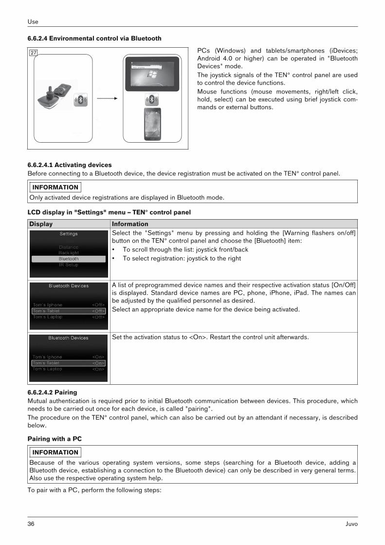
6.6.2.4 Environmental control via Bluetooth
27 PCs (Windows) and tablets/smartphones (iDevices;Android 4.0 or higher) can be operated in "BluetoothDevices" mode.The joystick signals of the TEN° control panel are usedto control the device functions. Mouse functions (mouse movements, right/left click,hold, select) can be executed using brief joystick commands or external buttons.
6.6.2.4.1 Activating devicesBefore connecting to a Bluetooth device, the device registration must be activated on the TEN° control panel.
INFORMATIONOnly activated device registrations are displayed in Bluetooth mode.
LCD display in "Settings" menu – TEN° control panel
Display InformationSelect the "Settings" menu by pressing and holding the [Warning flashers on/off]button on the TEN° control panel and choose the [Bluetooth] item:• To scroll through the list: joystick front/back• To select registration: joystick to the right
A list of preprogrammed device names and their respective activation status [On/Off]is displayed. Standard device names are PC, phone, iPhone, iPad. The names canbe adjusted by the qualified personnel as desired.Select an appropriate device name for the device being activated.
Set the activation status to <On>. Restart the control unit afterwards.
6.6.2.4.2 PairingMutual authentication is required prior to initial Bluetooth communication between devices. This procedure, whichneeds to be carried out once for each device, is called "pairing". The procedure on the TEN° control panel, which can also be carried out by an attendant if necessary, is describedbelow.
Pairing with a PC
INFORMATIONBecause of the various operating system versions, some steps (searching for a Bluetooth device, adding aBluetooth device, establishing a connection to the Bluetooth device) can only be described in very general terms.Also use the respective operating system help.
To pair with a PC, perform the following steps:
36
Use
Juvo

28
29
> Prerequisites:The device registration has been activated (seePage 36).Bluetooth devices can establish a connection to thiscomputer. If necessary, right-click the Bluetoothsymbol on the Windows interface of the PC (in thesymbols at the bottom right next to the time) ->Open settings -> Tick checkbox (see fig. 28).
1) Turn on the wheelchair control device.2) Select the Bluetooth mode on the TEN° control pan
el by pressing the [Profile/mode] button a numberof times if necessary.→ A list of the available devices is displayed.
3) Start the pairing process by selecting a suitabledevice name, e.g. Tom's laptop (To scroll throughlist: joystick front/back; to select registration: joystick to the right).→ The laptop symbol is displayed (see fig. 29).
4) Move the joystick forwards for approx. 10 secondsuntil an acoustic signal sounds.
5) Move the joystick back for approx. 10 seconds untilan acoustic signal sounds.→ The Bluetooth symbol at the top of the control
panel display (next to the time) should flash. TheTEN° control panel is ready to establish a connection.
6) Right-click the Bluetooth symbol on the PC (in thesymbols at the bottom right next to the time) ->Open settings -> Add device.
7) Wait until the device name selected in step 3 is displayed in the "Add device" PC window and confirm.The pairing is now performed.INFORMATION: If additional Bluetooth devicesare nearby, these are also displayed.
8) After the device has successfully been added, theBluetooth symbol is continually displayed in blue onthe TEN° control panel and the PC can be operatedusing the joystick on the control panel or via theconnected special control.INFORMATION: If the connection is not established directly, retrieve the Bluetooth menuonce again using the [Profile/mode] button.
Pairing with an Android device
INFORMATIONThe details of the steps that follow and the menus that are shown may differ due to the variety of existing Androidsoftware versions. Also use the respective Android help.
To pair with an Android device (e.g. smartphone, tablet), complete the following steps:
37Juvo
Use

30
31
> Prerequisite: The device registration has beenactivated (see Page 36).
1) Turn on the wheelchair control device. 2) On the Android device, open the Settings menu.3) Under the item Wireless and networks, open the
Bluetooth menu item and activate the Bluetoothfunction.Alternatively, open the Bluetooth menu item directly and activate the Bluetooth function.
4) Select the Bluetooth mode on the TEN° control panel by pressing the [Profile/mode] button a numberof times if necessary.→ A list of the available devices is displayed.
5) Start the pairing process by selecting a suitabledevice name, e.g. Tom's tablet (to scroll throughlist: joystick front/back; to select an entry: joystick tothe right).→ The tablet symbol is displayed (see Fig. at left).
6) Move the joystick forwards for approx. 10 secondsuntil an acoustic signal sounds.
7) Move the joystick back for approx. 10 seconds untilan acoustic signal sounds.→ The Bluetooth symbol at the top of the control
panel display (next to the time) should flash. TheTEN° control panel is ready to establish a connection.
8) Wait until the device name selected in step 5 is displayed on the Android device.WARNING! If additional Bluetooth devices arenearby, these are also displayed.
9) Tap the device name displayed on the Androiddevice to establish the pairing.
10) After the device has been successfully added, theBluetooth symbol is continually displayed in blue onthe TEN° control panel and the Android device canbe operated using the joystick on the control panelor via the connected special control.
Pairing with an iDeviceTo pair with an iOS device (e.g. iPhone, iPad), perform the following steps:
32 > Prerequisite: The device registration has beenactivated (see Page 36).
1) Turn on the wheelchair control device. 2) Tap Settings > Bluetooth on the iOS device.
Remain on this screen until the steps for pairingwith the TEN° control panel have been completed.
3) Select the Bluetooth mode on the TEN° control panel by pressing the [Profile/mode] button a numberof times if necessary.→ A list of the available devices is displayed.
4) Start the pairing process by selecting a suitabledevice name, e.g. Tom's iPhone (To scroll throughlist: joystick front/back; to select registration: joystick to the right).→ The iPhone symbol is displayed (see Fig. at
left).
38
Use
Juvo

33 5) Move the joystick forwards for approx. 10 secondsuntil an acoustic signal sounds.
6) Move the joystick back for approx. 10 seconds untilan acoustic signal sounds.→ The Bluetooth symbol at the top of the control
panel display (next to the time) should flash. TheTEN° control panel is ready to establish a connection.
7) Wait until the device name selected in step 4 is displayed on the iOS device.INFORMATION: If additional Bluetooth devicesare nearby, these are also displayed.
8) Tap the device name displayed on the iOS device toestablish the pairing (see illustration to the left).
9) After the device has been successfully added, theBluetooth symbol is continually displayed in blue onthe TEN° control panel and the iOS device can beoperated using the joystick on the control panel orvia the connected special control.
6.6.2.4.3 Selecting the connected devicesLCD display in Bluetooth mode – TEN° control panel
Display InformationThe pairing is maintained as soon as the Bluetooth connection to the devices hasbeen established.
The device can be selected by scrolling (joystick front/back).The selection is confirmed by moving the joystick to the right or left.
After a few seconds, a Bluetooth symbol is continually displayed in blue on the TEN°screen.The device can now be operated using the control elements of the wheelchair controlunit (e.g. joystick, special control).
The ID of the devices to which a Bluetooth pairing has been established is retained in the control panel. Thismeans that the connection can also be reestablished automatically:• if the wheelchair control unit is switched on again after being switched off,• if the external device was switched off and on again,• if the wheelchair has been outside the Bluetooth visibility of the external device and then returns to the visible
range again.
6.6.2.4.4 Deactivating devices1) Select the "Settings" menu by pressing and holding the warning flashers button on the TEN° control panel and
choose the [Bluetooth] item within the menu.2) Select the device you wish to deactivate from the list of available devices by scrolling (joystick front/back) and
confirm your selection by moving the joystick to the right.→ The device registration is now displayed with the additional information <Off>. The device can be activated
again in the same manner. A new pairing is not required.
39Juvo
Use

6.6.2.4.5 Operating mouse functions on a PCOnce a connection has been established to the PC, the mouse pointer can be controlled with the wheelchair control unit.
Mouse movementsThe mouse pointer moves according to the movements of the input device (e.g. joystick):• Mouse movement to the left/right: move joystick at normal speed to the left/right.• Mouse movement up/down: move joystick at normal speed front/back.
Mouse actionsMouse actions (such as clicking, scrolling) can be carried out in two ways depending on the equipment.a) Mouse actions by moving the joystick quickly and briefly:• Left mouse button function (choose selection): move joystick quickly and briefly to the left.• Right mouse button function: move joystick quickly and briefly to the right.• Scroll upwards: move joystick quickly and briefly to the front.• Scroll downwards: move joystick quickly and briefly to the back.• Double-click the left mouse button: quickly move the joystick to the left twice in quick succession.• Double-click the right mouse button: quickly move the joystick to the right twice in quick succession.The qualified personnel can also change assignments using individual programming so that e.g. a single joystickmovement is interpreted as a double-click.b) Mouse actions using external buttons:• One button corresponds to the left mouse button, the other button corresponds to the right mouse button.• Drag-and-drop is operated as with a traditional mouse: press and hold the button and drag with the joystick.
6.6.2.4.6 Operating iOS device functionsThe functions of the iOS device can be controlled using short/medium/long joystick movements on the TEN° control panel or corresponding operation of the special control elements. The assignment can be programmed by thequalified personnel.
6.6.2.4.7 Operating Android device functionsAs soon as the pairing has been completed, a cursor is superimposed on the display of the Android device. As with a PC, moving the joystick on the TEN° control panel or a connected special control element produces acorresponding cursor movement on the display of the Android device.Device functions such as taking phone calls, selecting contacts, accessing the internet, or sending texts are selected by moving the cursor to the corresponding function and moving the joystick quickly and briefly to the left.
6.6.2.5 Environmental control via infrared (IR)
34 Devices with an infrared remote control (TV, audio,video, projectors, etc.) can be controlled in "IR Menu"mode.The joystick signals of the TEN° control panel are usedto control the device functions.The device functions must be stored in the control unitusing a learning mode or programmed by the qualifiedpersonnel using a programming interface.
6.6.2.5.1 Operating IR devices
Retrieving/exiting "IR Menu" modeThe environmental control mode for devices with infrared remote control is retrieved/exited as follows:• Repeatedly pressing the [Profile/mode] button retrieves the profiles and operating modes in succession (see
Page 30; dependent on programming). • When "IR Menu" mode is reached, the programmed devices can be controlled in the home environment.
40
Use
Juvo

• The joystick is used to navigate within "IR Menu" mode (see below).• Pressing the [Profile/mode] button again allows you to switch to further operating modes and back to the driv
ing profiles again (dependent on programming).
Operating devicesThe following commands are provided for navigating within the "IR Menu" using a joystick:• Moving the joystick forwards moves the selection in the list of controllable devices up.• Moving the joystick backwards moves the selection in the list of controllable devices down.• Moving the joystick to the right or left displays the submenu for the corresponding device registration.• Moving the joystick to the right or left once more triggers the selected control command.
LCD display in "IR Menu" mode – TEN° control panel
Display InformationWhen "IR Menu" mode is selected on the control panel, a list of the devices whichcan be operated using environmental control is displayed.
A list of assigned control commands (IR codes) is stored for each device. Using theexample of a television set (TV), the following commands are available: [On], [Off],[Volume up], [Volume down], [Mute], [HDMI].
When the selected command is issued by the control panel, the entry is highlightedred in the list.
6.6.2.5.2 Learning and assigning IR codes
Programming devicesThe "IR Menu" mode is only available if commands for controlling devices (IR codes) have been saved in thewheelchair control device. There are two methods for storing IR codes:• "Learning" the IR code with the help of the corresponding remote control (see below),• Programming with the PC-based IR configurator (only by qualified personnel).
Learning prerequisitesTo allow an optimal learning procedure the following recommendations should be followed:• Put new batteries in the remote control to ensure the IR signal is of good quality.• Avoid directly exposing the IR sensor to daylight or lamps when signals are being transferred.• Position the remote control in front of the control panel during the learning process. When pressing a button on
the remote control, make sure that the remote control remains still (do not move it back and forth during learning). The ideal distance between the remote control and control panel is in the range between 40 to 100 mm(1.57" to 3.94").
LCD display in "Settings" menu – TEN° control panel
Display InformationRetrieve the "Settings" menu by pressing and holding the [Warning flashers on/off]button on the TEN° control panel. Then select the [IR Setup] menu item within the menu.
41Juvo
Use

Display InformationSelect a device, e.g. [TV]. The commands which have been set up for the device aredisplayed.
Select the command which needs to be learned, e.g. [Volume down].
Select [Learn code].
Point the TV remote control towards the control panel and press the desired button(e.g. [Volume down]) twice in succession. The learning mode is displayed on thecontrol panel.
INFORMATION: Hold the remote control at a distance of 40 to 100 mm (1.57"to 3.94") away from the receiver for infrared signals.The receiver is located on the front side of the control panel above the LCDscreen (see arrow).
A tick mark indicates that the learning process was successful.
If the learning process was not successful, an X is displayed. Repeat the learningprocess in this case.
6.6.2.5.3 Activating and deactivating IR codesThe learned IR codes can be activated or deactivated: • Once an IR code is deactivated, it no longer appears in the user menu. The corresponding command
(e.g. [Volume down]) can no longer be transmitted or executed.• If an IR code is activated, it appears in the user menu. The corresponding command (e.g. [Volume down]) can
be transmitted and executed.
42
Use
Juvo

LCD display in "Settings" menu – TEN° control panel
Display InformationRetrieve the "Settings" menu by pressing and holding the [Warning flashers on/off]button on the TEN° control panel. Then select the [IR Setup] menu item within the menu.
Deactivating an IR codeAn IR code can be deactivated by turning the rotary multi-selector on the TEN° control panel to the left. A deactivated IR code appears with an "X" next to the list entry.Activating an IR codeAn IR code can be activated by turning the rotary multi-selector on the TEN° controlpanel to the right. An activated IR code appears with a tick mark next to the list entry.
6.7 Driving functions6.7.1 Safety instructions
Hazards while driving
CAUTIONLack of riding experienceCollision, falling due to errors in handling the product ► Practise using the product on level, open ground first.
CAUTIONInsufficient support of the seated personRisk of falling out of the power wheelchair due to lack of restraint► Always use the installed belt system when driving in public.► Information about subsequent acquisition and mounting is provided by the qualified personnel that handed
the product over to you.
CAUTIONUncontrolled driving behaviour, unexpected sounds or odoursFalling, tipping, collision with persons or nearby objects due to defects► If any faults, defects or other hazards that can lead to personal injury are detected, the product must be taken
out of service immediately. This includes uncontrolled movements as well as sounds that are unexpected orpreviously not noted or odours that deviate significantly from the state of the product at the time of delivery.
► Please contact your authorised dealer.
CAUTIONDriving in the darkRisk of collisions with other traffic participants due to lack of lighting► Wear bright clothing or clothing with reflectors.► Use the lights on the wheelchair. ► If present: Ensure that the reflectors on the rear marker plate on the product are clearly visible.
Hazards during use of public transportation, elevators, lifting platforms
CAUTIONUse of elevators, lifting platformsRisk of tipping, collision with persons or nearby objects due to incorrect parking► Always turn the power wheelchair control unit off when using elevators or lifting platforms.► Make sure that the brake is engaged.
43Juvo
Use

CAUTIONSafe positioning when using public transitCrushing, pinching, impacts, collision with persons or objects, damage to the product due to human error► Only use public transit approved for the transportation of power wheelchairs. ► Always observe the current applicable transportation guidelines of the transit company and/or the legal
requirements in your country when using public transit.► Always ensure that you are held in place securely when travelling on public transport. To do so, use the
wheelchair areas, wheelchair bays and restraint systems provided. Turn the power wheelchair off before thevehicle starts to move.
► The transportation of a person sitting in a wheelchair in public transit constitutes a significant safety risk for allparticipants. We therefore recommend using the seats provided during transportation.
► While using public transit, you are not permitted to sit in the wheelchair without an approved personalrestraint system.
INFORMATIONOnly for control units with an electronic track stabiliser (gyro): The electronic track stabiliser is disrupted bythe movement of the means of transportation (bus; train; ship) and therefore cannot function. If you must travelshort distances in a moving means of transportation, please activate the "No assist" add-on profile. This switchesoff the electronic track stabiliser.
Hazards due to defective tyres
CAUTIONDefective tyresAccidents/falling due to poor traction, reduced braking force or lack of manoeuvrability► Maintain sufficient tyre pressure. The correct air pressure is printed on the sidewall of the tyre.► Ensure that the drive wheels have the same pressure.► Ensure that the tyres have sufficient tread depth. The tyres must be changed when the tread depth is less than
1 mm.
Additional information
INFORMATIONDuring use of the power wheelchair, electrical discharges (high voltage with low current; discharge via the user)may occur which are caused by factors such as friction. However, these do not represent a health hazard.Electrostatic discharge may also occur if the power wheelchair is equipped with puncture-proof tires. Retrofittingthe wheelchair with pneumatic tires can correct this problem.
6.7.2 Driving notes
General information:• Prior to each use, the charge level of the batteries has to be checked to avoid stalling due to drained batteries.• Beginners should always drive slowly.• Always take curves slowly.• Uncontrolled driving behaviour may occur on uneven ground. Therefore the speed must always be adjusted to
the ground conditions.• Driving backwards should be limited to manoeuvring or short distances on level ground.
Obstacles (steps, curbs, tracks):• Always approach obstacles directly from the front (never at an angle with only one front wheel). • Always reduce speed to cross over obstacles (e.g., select speed level 1 or 2).• Note the information on the critical obstacle height (see the section "Technical data"). Crossing obstacles
greater than the height difference specified there is not permitted. • Avoid jumping down from steps.• Do not lean out of the wheelchair while crossing obstacles.• Only cross railway systems and railway tracks in the designated areas.
44
Use
Juvo

• Do not negotiate railroad crossings too close to the edge. Otherwise, the wheels could accidentally move offthe railroad crossing.
• Stop before the railroad crossing and check to the left and right for safety.
Inclines and downgrades:• Note the information on permitted inclines and downgrades (see the section "Technical data"). Driving on
inclines or downgrades exceeding this percentage is not permitted. The wheelchair may otherwise tilt and notbrake safely.
• The control unit and the motors have to be protected against overloading. Therefore, the continuous climbingability depends on the overall weight (wheelchair weight + user weight + payload) as well as the ground conditions, exterior temperature, battery voltage and driving style of the user. In individual cases, the continuousclimbing ability can be significantly lower than the value specified.
• In order to navigate downhill gradients safely, the speed must be reduced according to the slope (e.g. selectspeed level 1).
• Never drive downhill backwards.
Terrain:• The speed must be reduced in dangerous areas (e.g. select speed level 1). • Typical dangerous areas include:
– Narrow paths along waterways/slopes/cliffs (e.g., quay walls, dikes, etc.)– Cramped rooms or areas– Steep downgrades (e.g., in the mountains, facing streets)– Unsurfaced areas (e.g., on construction sites, intersections, train crossings)– Snow-covered or icy areas
Using the control unit:• The control system always has to be mounted securely and the joystick position must be correct.• The hand or limb used to operate the joystick should be supported, for example on the side panel arm pad.• The joystick must not be used as the sole support for the hand or limb, because wheelchair movements and
bumps could cause a loss of control.• If the power wheelchair does not drive at full speed even when the battery is fully charged, the selected speed
level should be checked. Contact the qualified personnel if increasing the speed level does not solve the problem.
• The intelligent speed control system minimises the effects of slopes and different types of terrain.
Further instructions for use• Attaching loads such as backpacks and the like can adversely affect stability. Ottobock recommends using a
luggage carrier. If this is not available, backpacks should always be secured to the back frame with theshoulder straps. The maximum load capacity of 5 kg (11 lbs) should not be exceeded.
• The recommended total width for category B power wheelchairs in an operational state is 700 mm (27.5").This specification should ensure unhindered use of escape routes, for example. Please note that the wheelchairdimensions may exceed the recommended value in versions with very large seat widths (for more informationsee the section "Technical data": see Page 111).
• The wheelchairs in this series fully satisfy the minimum technical requirements for wheelchairs transportable bytrain. Note however that, due to the variety of variants and settings, not every specific power wheelchair meetsall minimum requirements (for more information see the section "Appendix" > "Threshold values for wheelchairs transportable by train": see Page 119).
6.7.3 Switching on and off
WARNINGLack of brake functionalityFalling, tipping over, collision with persons or nearby objects due to lack of inspection► Ensure that the brake release lever is in the driving position every time before you drive (see Page 50).► Check the control unit display to ensure that the brakes are operational and functional (see Page 105).
45Juvo
Use
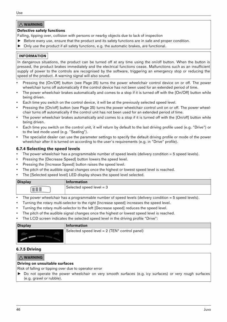
WARNINGDefective safety functionsFalling, tipping over, collision with persons or nearby objects due to lack of inspection► Before every use, ensure that the product and its safety functions are in safe and proper condition.► Only use the product if all safety functions, e.g. the automatic brakes, are functional.
INFORMATIONIn dangerous situations, the product can be turned off at any time using the on/off button. When the button ispressed, the product brakes immediately and the electrical functions cease. Malfunctions such as an insufficientsupply of power to the controls are recognised by the software, triggering an emergency stop or reducing thespeed of the product. A warning signal will also sound.
• Pressing the [On/Off] button (see Page 25) turns the power wheelchair control device on or off. The powerwheelchair turns off automatically if the control device has not been used for an extended period of time.
• The power wheelchair brakes automatically and comes to a stop if it is turned off with the [On/Off] button whilebeing driven.
• Each time you switch on the control device, it will be at the previously selected speed level.• Pressing the [On/off] button (see Page 25) turns the power wheelchair control unit on or off. The power wheel
chair turns off automatically if the control unit has not been used for an extended period of time. • The power wheelchair brakes automatically and comes to a stop if it is turned off with the [On/off] button while
being driven.• Each time you switch on the control unit, it will return by default to the last driving profile used (e.g. "Drive") or
to the last mode used (e.g. "Seating").• The specialist dealer can use the parameter settings to specify the default driving profile or mode of the power
wheelchair after it is turned on according to the user's requirements (e.g. in "Drive" profile).
6.7.4 Selecting the speed levels• The power wheelchair has a programmable number of speed levels (delivery condition = 5 speed levels).• Pressing the [Decrease Speed] button lowers the speed level.• Pressing the [Increase Speed] button raises the speed level.• The pitch of the audible signal changes once the highest or lowest speed level is reached.• The [Selected speed level] LED display shows the speed level selected.
Display InformationSelected speed level = 3
• The power wheelchair has a programmable number of speed levels (delivery condition = 5 speed levels).• Turning the rotary multi-selector to the right [Increase speed] increases the speed level.• Turning the rotary multi-selector to the left [Decrease speed] reduces the speed level.• The pitch of the audible signal changes once the highest or lowest speed level is reached.• The LCD screen indicates the selected speed level in the driving profile "Drive":
Display InformationSelected speed level = 2 (TEN° control panel)
6.7.5 Driving
WARNINGDriving on unsuitable surfacesRisk of falling or tipping over due to operator error► Do not operate the power wheelchair on very smooth surfaces (e.g. icy surfaces) or very rough surfaces
(e.g. gravel or rubble).
46
Use
Juvo

WARNINGDriving on slopes, over obstaclesFalling, tipping over due to user error► Only cross obstacles or negotiate ascents or descents that are within the permitted maximums. For more
information, see the section "Technical data" (see Page 111).► Do not cross over any obstacles while ascending or descending inclines.► Avoid embarking and disembarking on inclines and slopes.► Do not drive over stairs.
WARNINGLonger braking distanceRisk of falling, tipping over or collision due to operator error► Note that the braking distance is much longer on downgrades than on the level.► Also reduce speed when driving downhill (e.g. select speed level 1).
INFORMATIONThe control unit of the product switches to a safe mode at elevated temperatures and after driving uphill for extended periods of time, limiting the performance of the product.The user is able to drive the product out of a hazardous situation at any time. After a short time, the product is fullyoperational again.
The power wheelchair is controlled by moving the joystick:• The further the joystick is deflected from the centre position, the faster the power wheelchair will drive in this
direction. • The maximum speed at full deflection of the joystick depends on the selected speed level.• Releasing the joystick automatically activates the brake function, bringing the power wheelchair to a halt. The mechanical brakes are activated automatically when the power wheelchair comes to a stop so that it cannotroll.
6.7.6 RangeThe following factors influence the range of the product:• Battery capacity• Battery age (batteries reach their full capacity only after approx. 20 charge cycles, and the product can
achieve the stated range only then)• Ambient temperature• Driving conditions (e.g. terrain profile, condition of surface)• Charging method• Type and number of power options• Overall weight of the wheelchair with selected equipment• Use of power options• Body weight of user• Tyres (air pressure, tyre tread depth)
47Juvo
Use

6.7.7 Anti-tipper
35 The anti-tipper makes driving safer (see fig. 35). Withrear-wheel drive, it prevents the wheelchair from tippingtoo far backward. The anti-tipper is mounted so that the ground clearanceis at least 50 mm.
36 The swing-away, spring-loaded anti-tipper rollers stabilise the front-wheel drive power wheelchair when braking while driving downhill.They swing back when driving against a curb,for example.The anti-tipper is mounted so that the ground clearanceis at least 50 mm.
6.7.8 Drive-away lock6.7.8.1 VR2 control unit
INFORMATIONThis function is currently not enabled. For questions related to enabling it, please consult the qualified personnel that adapted the product or the manufacturer's service (see inside back cover or back page for addresses).
The power wheelchair control unit features an electronic drive-away lock, which is disabled by default.If the function has been ordered and enabled, the drive-away lock can be activated or deactivated as follows usingthe control panel:
Activating the drive-away lock1) Press and hold the [On/off] switch while the control unit is turned on.2) Release the [On/off] button after a beep sounds (approx. 1 second).3) Push the joystick all the way forward until a beep sounds.4) Push the joystick all the way back until a beep sounds.→ A long beep confirms that the drive-away lock was activated.→ The control unit turns itself off. → A sequential indicator on the [Selected speed level] LED display indicates that the drive-away lock is active:
Display InformationSequential indicator on the "Speed levels"LED display
Drive-away lock
Deactivating the drive-away lockWhen the unit is turned on, the [Charge level] LED display is off and the [Selected speed level] LED indicator is insequential indicator mode.1) Push the joystick all the way forward until a beep sounds.
48
Use
Juvo

2) Push the joystick all the way back until a beep sounds.3) Release the joystick.→ A long beep confirms that the driving function is enabled.→ The [Charge level] LED indicator is lit.→ The drive-away lock is deactivated and driving is enabled.
TroubleshootingThe drive-away lock remains active if the joystick is not moved correctly.1) Turn the control unit off in order to deactivate the drive-away lock again.2) Turn the power wheelchair on.3) Deactivate the drive-away lock again.
6.7.8.2 R-Net control unit
INFORMATIONThis function is currently not enabled. For questions related to enabling it, please consult the qualified personnel that adapted the product or the manufacturer's service (see inside back cover or back page for addresses).
The power wheelchair control unit features an electronic drive-away lock. This function is activated/deactivated viathe control panel.
Activating the drive-away lock1) Press and hold the [On/off] button while the control unit is turned on.2) Release the [On/off] button after a beep sounds (approx. 1 second).3) Push the joystick all the way forward until a beep sounds.4) Push the joystick all the way back until a beep sounds.→ A long beep confirms that the drive-away lock was activated.→ The control unit turns itself off. → The key symbol on the LCD screen indicates that the drive-away lock is activated:
Symbol InformationDrive-away lock
Deactivating the drive-away lock1) Push the [On/off] button on the control panel.
→ The control unit is turned on. The LCD screen indicates that the drive-away lock is activated.2) Push the joystick all the way forward until a beep sounds.3) Push the joystick all the way back until a beep sounds.4) Release the joystick.→ A long beep confirms that the driving function is enabled.→ The battery indicator and speed level are shown on the LCD screen.→ The drive-away lock is deactivated and driving is enabled.
TroubleshootingThe drive-away lock remains active if the joystick is not moved correctly.1) Turn the control unit off in order to deactivate the drive-away lock again.2) Turn the power wheelchair on.3) Deactivate the drive-away lock again.
49Juvo
Use

6.7.9 Adjusting the driving characteristics
WARNINGIncorrect configuration settingsFalling, tipping over, collision due to programming errors► Programming may only be performed by qualified personnel trained by the manufacturer. The manufacturer of
the product and the control unit manufacturer are not liable in case of damage caused by programming whichwas not performed properly and/or which was not adjusted properly according to the user's abilities.
Adjusting and setting the speed, acceleration and deceleration values to the individual user requirements is performed exclusively by qualified personnel trained by the manufacturer.
6.8 Enabling/disabling the brakes
WARNINGUncontrolled rollingRisk of collision with persons or nearby objects due to unlocked brake► Note the lack of brake functionality when the brake is deactivated. The brake function may only be released in
the presence of an attendant.► Should the user be unable to release the brake himself, the brake can be released by the attendant.► Note that when the power wheelchair is moved on an incline, the attendant must provide the required brake
force.► Ensure that the wheel lock is engaged each time when parking the power wheelchair.
WARNINGImproper maintenance, repair, or adjustment work on the brakeFalling, tipping, collision with persons or nearby objects due to improper operation► Repairs and adjustments to the brake may only be made by qualified personnel trained by the manufacturer.
Incorrect settings can lead to a loss of braking power.
CAUTIONExposed pinch pointsCrushing, pinching due to incorrect handling► Grasp the brake release levers as close to the outer end as possible to avoid pinching your fingers between
the splash guard and brake release lever.
INFORMATIONWhen the joystick is activated while the brakes are unlocked, the control unit emits an error signal on the controlpanel. If this is not the case, something has malfunctioned and the problem must be eliminated immediately by aspecialist dealer.
It is possible to push the power wheelchair in case of control unit failure or insufficient battery charge level. To do so, the brake is deactivated via the mechanical release. The brake releases are located on the right and leftof the driving motors.
37 Releasing/deactivating the brake1) If needed: Turn the control device off.2) Push the brake release levers down (see fig. 37,
item 1).→ The drive motors are released and the power wheel
chair has no braking function.→ After switching the control device on: The control
device recognises that the brake has been releasedand deactivates the driving function.
→ A warning appears on the control panel.Enabling/activating the brake1) If needed: Turn the control device off.
50
Use
Juvo

2) Push the brake release lever up (see fig. 37,item 2).
3) Switch on the control device.→ The driving function is activated.
38 Releasing/deactivating the brake1) If needed: Turn the control device off.2) Push the brake release levers down (see fig. 38,
item 1).→ The drive motors are released and the power wheel
chair has no braking function.→ After switching the control device on: The control
device recognises that the brake has been releasedand deactivates the driving function.
→ A warning appears on the control panel.Enabling/activating the brake1) If needed: Turn the control device off. 2) Push the brake release lever up (see fig. 38,
item 2).3) Switch on the control device.→ The driving function is activated.
39 Releasing/deactivating the brake1) If needed: Turn the control device off.2) Push the brake release levers down (see fig. 39,
item 1).→ The drive motors are released and the power wheel
chair has no braking function.→ After switching the control device on: The control
device recognises that the brake has been releasedand deactivates the driving function.
→ A warning appears on the control panel.Enabling/activating the brake1) If needed: Turn the control device off. 2) Push the brake release lever up (see fig. 39,
item 2).3) Switch on the control device.→ The driving function is activated.
40 Releasing/deactivating the brake1) If needed: Turn the control device off.2) Push the brake release levers down (see fig. 40,
item 1).→ The drive motors are released and the power wheel
chair has no braking function.→ After switching the control device on: The control
device recognises that the brake has been releasedand deactivates the driving function.
→ A warning appears on the control panel.Enabling/activating the brake1) If needed: Turn the control device off. 2) Push the brake release lever up (see fig. 40,
item 2).3) Switch on the control device.→ The driving function is activated.
51Juvo
Use

Brake deactivated: warning on control panel
Display Information
Flashing light
Brake released
Brake deactivated: warning on control panel
Display InformationBrake released
6.9 Batteries/charging process6.9.1 Safety instructions
CAUTIONFailure to check the charge level before putting into operationInjury to the user due to stopping suddenly, problems due to unplanned stalling► Check the charge level of the batteries before each use.► Always make sure that the charge level of the batteries is sufficient for the planned distance.► Never drive with the batteries almost fully discharged.► When the batteries are almost fully discharged, charge them promptly.
NOTICEUnauthorised battery replacementBattery damage due to unauthorised changes to the product► Battery replacement may only be performed by qualified personnel trained by the manufacturer.► The charging profile of the battery charger established at the factory matches the batteries included in the
scope of delivery and may not be altered independently.
6.9.2 General
INFORMATION► Please note that Ottobock has delivered this power wheelchair without batteries as per the order.► Please note that batteries have been installed in your power wheelchair which are not included in Ottobock's
modular system. Ottobock assumes no liability for combinations with accessories from other manufacturersnot included in Ottobock's modular system.
► Prior to using this accessory, please read and observe the instructions for use / manufacturer's instructionsfrom the other manufacturer. These are included with the instructions for use.
► In case of questions or problems with these accessories, please contact the qualified personnel who adjustedthis product.
The power wheelchair is equipped with maintenance-free batteries. See the section "Technical data" for the batterycapacity. The batteries are located under the seat of the power wheelchair, below the battery cover. Prolonged driving when the battery is low results in deep discharge and battery damage. If the power wheelchair isbeing driven when the battery is low the control unit switches to creep speed to save power.
6.9.3 Battery charging informationThe range of the power wheelchair is determined by the battery capacity. The battery capacity is influenced bymany factors. In addition to the temperature, battery age and driving conditions, the charging cycle also has a pronounced effect on the capacity and therefore on the range.Batteries reach their full capacity only after approx. 20 charge cycles. Only if the full capacity of the batteries hasbeen reached can the power wheelchair achieve the stated range.
52
Use
Juvo

At temperatures of < 0 °C/32 °F the battery capacity drops by up to 35% in relation to the capacity for an outsidetemperature of 20 °C/68 °F. This shortens the range of the power wheelchair accordingly. Moreover the chargelevel displayed on the control panel can differ more significantly from the actual battery capacity.The following information should be observed for an optimal charging cycle:• The batteries can be charged at any time, regardless of the remaining charge level.• It takes about 10 to 12 hours until a discharged battery (only 1 flashing segment) is fully charged. When the
charging process is complete, the battery charger can remain connected to the power wheelchair with no riskof overcharging or damaging the battery. The battery charger features a programmed recharging phase thatwill maintain the battery capacity at the level that has been reached.
• If the power wheelchair is used every day, the battery should be charged every night.• Never discharge the batteries completely (deep discharge). • The batteries will gradually discharge if the wheelchair is not used for extended periods of time. If the power
wheelchair is not used for an extended period, the batteries should be charged 1 x per week to maintain theircapacity.
• After charging the batteries, the circuit breaker should be deactivated if the wheelchair is not used for morethan 3 days.
• The power wheelchair control device must be switched off while the batteries are charging to allow all of thecharging current to be fed into the battery.
6.9.4 Battery charger
INFORMATION► Please note that Ottobock has delivered this power wheelchair without a battery charger as per the order.► Please note that you have received a battery charger which is not included in Ottobock's modular system.
Ottobock assumes no liability for combinations with accessories from other manufacturers not included inOttobock's modular system.
► Prior to using this battery charger, please read and observe the instructions for use / manufacturer's instructions from the other manufacturer. These are included with the instructions for use.
► In case of questions or problems with this accessory, please contact the qualified personnel who adjusted thisproduct.
NOTICEImproper use of the battery chargerDamage to the battery charger, damage to the battery due to user error► Only use battery chargers which have been verified and approved for use with the respective batteries. ► Ensure that the information on the battery charger nameplate matches the country-specific voltage of the
respective mains grid.► Only use the battery charger within the specified temperature and humidity limits.► Place the battery charger on a level surface.► If you locate the battery charger near a window, protect it from direct sunlight.► Avoid overheating of the battery charger. Do not cover the ventilation slits in the case.► Switch the control unit off during the charging process so that all of the charging current is fed into the bat
tery.► Avoid dust, dirt and moisture.► Only clean the battery charger with a dry cloth.
The battery charger is designed for maintenance-free and low-maintenance batteries. Please see the instructions for use supplied with the battery charger for further details on use and on the LED displays.
6.9.5 Charging the battery
WARNINGImproper use of the battery chargerRisk of electric shock due to contact with live components► Do not touch live electrical components. The battery charger and its cables are live when the charger is on.► Do not remove any insulation or protective covers.
53Juvo
Use

WARNINGDischarge of explosive gases during battery chargingBurns due to explosion after a user error► Ensure sufficient ventilation in enclosed spaces.► Do not smoke or light fires.► Sparks must be avoided. Switch the battery charger off and disconnect the mains plug before you disconnect
the battery.► Do not cover the ventilation slits in the case.► Only use battery chargers which have been verified and approved by the manufacturer for use with the
respective batteries (observe information on the battery charger). Non-observance may result in explosion ofthe battery, resulting in a health hazard.
NOTICEImproper chargingDamage to the battery due to user error► Please note the manufacturer's instructions for the batteries being used. Follow the battery manufacturer
safety instructions.► Avoid deep discharge of the battery. The manufacturer does not assume any liability for damage due to deep
discharge.► Charge the battery immediately when the control panel indicates a deep discharge (see section "Buttons and
display functions").
INFORMATIONCharge the batteries of the power wheelchair for a longer time (over the course of 15 to 20 hours) once a week toensure a long battery service life.
41 Charging process via the control panel1) Turn the control unit on the power wheelchair off.2) Plug the battery charger plug into the charging
receptacle on the power wheelchair control panel.INFORMATION: Please note that charging viathe charging receptacle on the control panelmay only be carried out at a current of maximum 10 A.
3) Connect the battery charger to the mains socket.→ The charging process starts automatically, and
the battery charge condition is indicated by theLED indicator on the control panel and on thebattery charger.
4) Turn the battery charger off and pull the plug out ofthe mains socket when the charging process iscomplete.
5) Disconnect the charging plug from the control panel.
6) Turn the power wheelchair control unit on. Thepower wheelchair is ready to use.
54
Use
Juvo
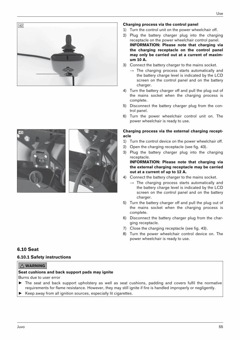
42 Charging process via the control panel1) Turn the control unit on the power wheelchair off.2) Plug the battery charger plug into the charging
receptacle on the power wheelchair control panel.INFORMATION: Please note that charging viathe charging receptacle on the control panelmay only be carried out at a current of maximum 10 A.
3) Connect the battery charger to the mains socket.→ The charging process starts automatically and
the battery charge level is indicated by the LCDscreen on the control panel and on the batterycharger.
4) Turn the battery charger off and pull the plug out ofthe mains socket when the charging process iscomplete.
5) Disconnect the battery charger plug from the control panel.
6) Turn the power wheelchair control unit on. Thepower wheelchair is ready to use.
43 Charging process via the external charging receptacle1) Turn the control device on the power wheelchair off.2) Open the charging receptacle (see fig. 43).3) Plug the battery charger plug into the charging
receptacle.INFORMATION: Please note that charging viathe external charging receptacle may be carriedout at a current of up to 12 A.
4) Connect the battery charger to the mains socket.→ The charging process starts automatically and
the battery charge level is indicated by the LCDscreen on the control panel and on the batterycharger.
5) Turn the battery charger off and pull the plug out ofthe mains socket when the charging process iscomplete.
6) Disconnect the battery charger plug from the charging receptacle.
7) Close the charging receptacle (see fig. 43).8) Turn the power wheelchair control device on. The
power wheelchair is ready to use.
6.10 Seat6.10.1 Safety instructions
WARNINGSeat cushions and back support pads may igniteBurns due to user error► The seat and back support upholstery as well as seat cushions, padding and covers fulfil the normative
requirements for flame resistance. However, they may still ignite if fire is handled improperly or negligently.► Keep away from all ignition sources, especially lit cigarettes.
55Juvo
Use

CAUTIONSkin damageRisk of skin reddening during long-term use► Do not use the seat until it has been adjusted by a suitably qualified or experienced person.► Examine the skin for redness on a regular basis. Skin reddening is a clinical indicator of tissue damage.► If redness of the skin or other problems occur during use, stop using the seat immediately. Only start using
the seat again after consulting the prescribing doctor or therapist.
CAUTIONFailure to observe care instructionsSoreness due to user error► Note that no seating systems can completely eliminate sitting pressure or fully prevent possible soreness.► When using the seat, always ensure good skin care and regular pressure redistribution.
NOTICEImproper useDamage to the seat surface due to user error► Do not allow the seat to come into contact with sharp objects. This also applies to animals such as pet cats
with sharp claws.► If the seat is expected to come into contact with liquid, such as spilt drinks or episodes of incontinence,
always use it in conjunction with a liquid-repellent cover. ► Only use the Ottobock incontinence covers for this product. Contact the qualified personnel to obtain a spare
Ottobock cover.
6.10.2 Seat typeThe product is equipped with a standard seat.
44 The product is equipped with a VAS seat (VariableAdjust Seat).This seat type allows the technician to quickly vary theseat depth, seat and back width, and centre of gravitysettings.
6.10.3 Contoured padsThe contoured pads provide the user with good lateral support.
56
Use
Juvo

45 The contoured pads are offered in the flat contouredand deep contoured versions. The pads can also becovered in either cloth or artificial leather. An incontinence cover is available in addition.
Illustrated: Contoured pads in the version with clothcover, deep contoured.
6.10.3.1 Taking off and putting on the covers
Cloth/artificial leather coverBefore putting on the incontinence cover, the cloth and artificial leather covers have to be taken off the seat pad.In addition, the cloth cover can be taken off the seat and back pads for general cleaning.
46 Taking off/putting on the cover 1) Pull the seat or back pad off the hook-and-loop
strap.2) Open the zipper of the cover and remove the foam
pad.3) Now the cover can be taken off.4) To put on the cover, insert the foam pad into the
cover again with proper alignment.5) Close the zipper and secure the seat or back pad
again on the hook-and-loop strap.
Incontinence cover
INFORMATIONSince the artificial leather cover is relatively tight, the incontinence cover is used with the cloth cover as a rule.Nevertheless, you should take the artificial leather cover off from time to time and check whether liquid has gotteninto the foam pad through the seams. You should clean the foam pad if this is the case.
The incontinence cover is positioned under the seat cover. It protects the foam pad against wetness.
47 Putting on the cover1) Remove the cover.2) Slide the foam pad into the incontinence cover (top
left).3) Pull the open end of the incontinence cover up and
lay it onto the foam pad (top right).4) Pull the overhanging end of the incontinence cover
down and close it on the underside of the foam pad(bottom).
5) Put on the cover.
57Juvo
Use
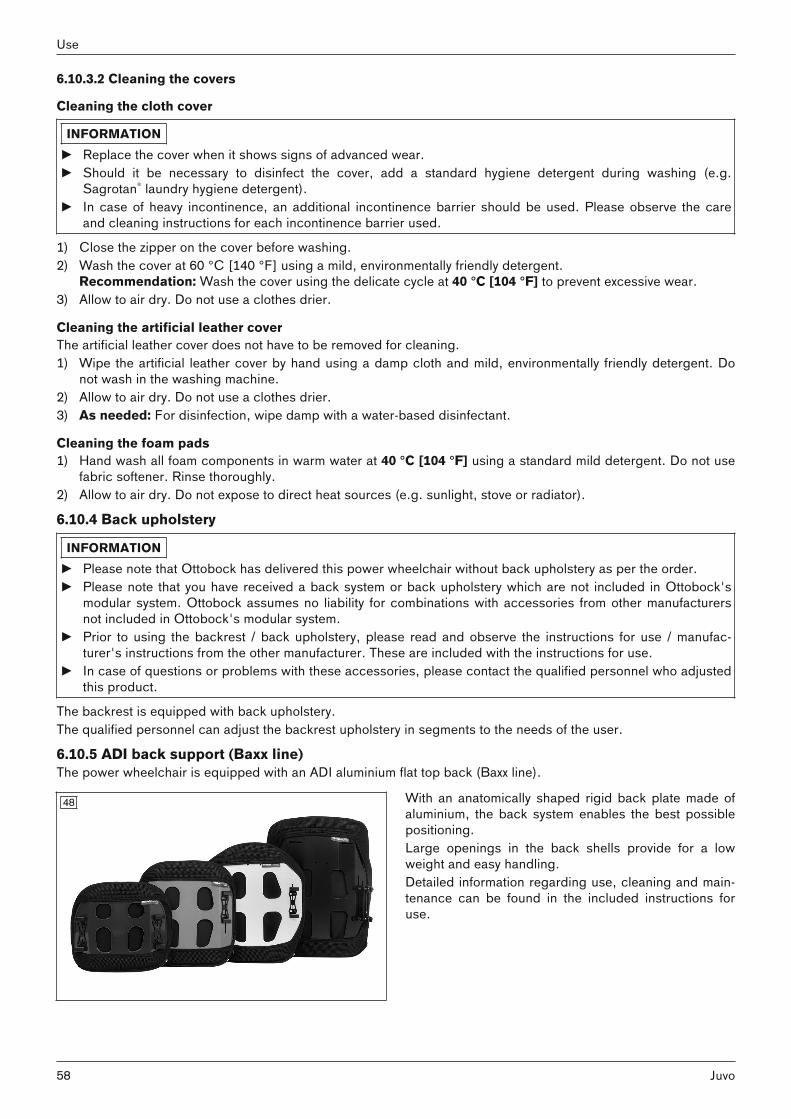
6.10.3.2 Cleaning the covers
Cleaning the cloth cover
INFORMATION► Replace the cover when it shows signs of advanced wear.► Should it be necessary to disinfect the cover, add a standard hygiene detergent during washing (e.g.
Sagrotan® laundry hygiene detergent).► In case of heavy incontinence, an additional incontinence barrier should be used. Please observe the care
and cleaning instructions for each incontinence barrier used.
1) Close the zipper on the cover before washing.2) Wash the cover at 60 °C [140 °F] using a mild, environmentally friendly detergent.
Recommendation: Wash the cover using the delicate cycle at 40 °C [104 °F] to prevent excessive wear.3) Allow to air dry. Do not use a clothes drier.
Cleaning the artificial leather coverThe artificial leather cover does not have to be removed for cleaning.1) Wipe the artificial leather cover by hand using a damp cloth and mild, environmentally friendly detergent. Do
not wash in the washing machine.2) Allow to air dry. Do not use a clothes drier.3) As needed: For disinfection, wipe damp with a water-based disinfectant.
Cleaning the foam pads1) Hand wash all foam components in warm water at 40 °C [104 °F] using a standard mild detergent. Do not use
fabric softener. Rinse thoroughly.2) Allow to air dry. Do not expose to direct heat sources (e.g. sunlight, stove or radiator).
6.10.4 Back upholstery
INFORMATION► Please note that Ottobock has delivered this power wheelchair without back upholstery as per the order.► Please note that you have received a back system or back upholstery which are not included in Ottobock's
modular system. Ottobock assumes no liability for combinations with accessories from other manufacturersnot included in Ottobock's modular system.
► Prior to using the backrest / back upholstery, please read and observe the instructions for use / manufacturer's instructions from the other manufacturer. These are included with the instructions for use.
► In case of questions or problems with these accessories, please contact the qualified personnel who adjustedthis product.
The backrest is equipped with back upholstery. The qualified personnel can adjust the backrest upholstery in segments to the needs of the user.
6.10.5 ADI back support (Baxx line)The power wheelchair is equipped with an ADI aluminium flat top back (Baxx line).
48 With an anatomically shaped rigid back plate made ofaluminium, the back system enables the best possiblepositioning. Large openings in the back shells provide for a lowweight and easy handling. Detailed information regarding use, cleaning and maintenance can be found in the included instructions foruse.
58
Use
Juvo

6.10.6 Seat cushionThis power wheelchair was ordered and delivered with a seat cushion. Wheelchair seat cushions are used for pressure redistribution while sitting. Depending on the version, the seatcushion contains a resilient foam base and, if applicable, additional gel or air-filled inserts. The foam base is anatomically shaped in some cases.The covers and breathable materials reduce shear forces and ensure a high level of seating comfort for the user.The seat cushion can be removed for cleaning. Following cleaning, the seat cushion is secured to the seat by ahook-and-loop fastener to prevent sliding. Detailed information regarding use, cleaning and maintenance can be found in the included instructions for use forthe seat cushion.
6.10.7 Recaro® seatThe Recaro® seat provides individually adjustable, comprehensive seating comfort.
6.10.7.1 Settings
49 Adjusting the back angle1) Turn the knob on the right or left side of the back
rest (see fig. 49, item 2).2) Change the backrest angle to the desired position.
CAUTION! Note that the maximum backrestangle is 30° while standing and 20° while driving.
Adjusting the lateral supports in the lumbar region
INFORMATIONThis information only applies to the Recaro® LT model.
1) Turn the dial on the side of the backrest towards the front.→ The two lateral supports are moved closer together.
2) Turn the dial on the side of the backrest towards the rear.→ The two lateral supports are moved further apart.
Adjusting the padsThe seat surfaces X and W are equipped with a pull-out pad at the front of the seat bottom. The adjustment leverfor the pad is located below the seat bottom.1) Pull the pad adjustment lever up and hold it there.2) Move the pad to the desired position.3) Release the adjustment lever and let it engage. The adjustment lever is in a safe position if it engages audibly
and has returned to its initial position.
Adjusting the headrestThe height and tilt angle of the headrest are adjustable.
59Juvo
Use
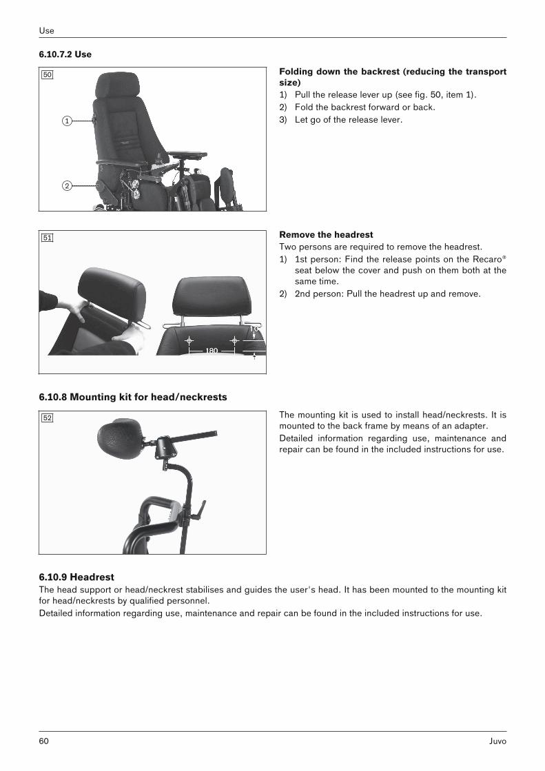
6.10.7.2 Use
50 Folding down the backrest (reducing the transportsize)1) Pull the release lever up (see fig. 50, item 1).2) Fold the backrest forward or back.3) Let go of the release lever.
51 Remove the headrestTwo persons are required to remove the headrest.1) 1st person: Find the release points on the Recaro®
seat below the cover and push on them both at thesame time.
2) 2nd person: Pull the headrest up and remove.
6.10.8 Mounting kit for head/neckrests
52 The mounting kit is used to install head/neckrests. It ismounted to the back frame by means of an adapter. Detailed information regarding use, maintenance andrepair can be found in the included instructions for use.
6.10.9 HeadrestThe head support or head/neckrest stabilises and guides the user's head. It has been mounted to the mounting kitfor head/neckrests by qualified personnel.Detailed information regarding use, maintenance and repair can be found in the included instructions for use.
60
Use
Juvo

6.11 Power seat functions6.11.1 Safety instructions
WARNINGDriving with power seat functionsFalling, tipping over due to driving with unallowable seat settings► Only drive in road traffic and on inclines and downgrades with the seat tilt and seat height adjustments
lowered and with a vertical backrest. Always use a belt system.► Slightly tilt the seat to the rear when driving down obstacles in a forward direction (e.g. curbs) and reduce the
speed.► Drive with the seat raised or with the seat tilt/back angle adjustment activated only for short distances at
home. Always use the speed level 1 for this. Note that the field of vision is limited when driving. Always use abelt system.
► Use the seat height adjustment and the seat tilt only on firm, level ground.► To avoid uncontrolled driving movements, ensure that the control unit is always in "Power seat functions"
mode before using the power seat functions.► To avoid hazardous situations, note the correct deflection direction of the joystick (see Page 67).
WARNINGOverloadingRisk of falling, tipping over due to non-compliance with technical data► Note that the maximum permitted load of the power wheelchair may be reduced when using power seat func
tions (see the section "Technical data").
WARNINGExposed pinch pointsPinching, crushing of limbs (e.g. fingers) due to lack of caution in danger areas, damage to the product► Note that when seat functions are used, inherent pinch and shear points are located between the seat frame
and the power wheelchair frame.► Ensure that no body parts, such as hands or feet, are in the danger area while the seat functions are used.► Ensure that no interfering objects, such as clothing or other obstacles, are in the danger area while the seat
functions are used.
WARNINGOverloading of the actuatorsRisk of falling, tipping, pinching, crushing of limbs due to improper handling ► Avoid overloading the actuators. Overloading may cause components to break, leading to uncontrolled drop
ping of the seat or causing the backrest to flip back.
WARNINGLack of maintenanceSevere user injuries, damage to the product due to maintenance errors ► Check the adjustment functions for visible signs of damage at least 1 x per month and ensure all screw con
nections are tight.
NOTICEImproper use of electric seat optionsDamage to the product through user error► When using electric seat options, note that the seat function actuators are not designed for continuous use,
only for short-term use under limited loads (10% load, 90% idle time).► Observe the following guidelines: at maximum load capacity, 10 seconds of activation time must be followed
by approx. 90 seconds of idle time. The power seat functions are considered independently of the drivingfunction for this purpose.
► Only activate the power seat functions if no fault or error is present.
61Juvo
Use

6.11.2 Power seat height adjustment
WARNINGImproper use of the seat height adjustment featureFalling, tipping over due to driving with unallowable seat settings► Use the seat height adjustment feature only with the backrest in the upright position.► Drive in street traffic only with the seat height adjustment lowered.► Even when driving indoors, fasten the belts and do not lean out beyond the seat surface when the seat height
adjustment feature is raised.► Ensure that creep speed is activated when the seat height adjustment function is used. If this is not the case,
contact a specialist dealer immediately. Only use the power wheelchair with the seat height adjustment in itslowest position until the fault is rectified.
NOTICERisk of transportation damageDamage to the product through user error► Always lower the seat height adjustment feature fully for loading or transportation.
INFORMATION► Please also observe the generally applicable safety instructions in the section "Power seat functions" >
"Safety instructions" (see Page 61).► Observe the instructions for use in the sections "Controlling power seat functions" (see Page 66) and "Joy
stick functions" (see Page 67).
53 The power seat height adjustment feature raises theseat bottom by 350 mm (13.8") using a motor drive.The seat can be moved up continuously to the heightspecified. The driving function can be used indoors even when theseat is raised. The speed is decreased when the seat israised. This is indicated on the control panel as follows:
54 The power seat height adjustment feature raises theseat bottom by 350 mm (13.8") using a motor drive.The seat can be moved up continuously to the heightspecified. The driving function can be used indoors even when theseat is raised. The speed is decreased when the seat israised. This is indicated on the control panel as follows:
VR 2 control unit
Display InformationRestricted speed (creep speed)INFORMATION: The [Selected speed level] LED display flashes.
62
Use
Juvo

R-Net control unit – TEN° control panel
Symbol InformationRestricted speed (creep speed)Turtle symbol lights up yellow: automatic speed reduction (e.g. because a seatfunction was activated)
6.11.3 Power seat tilt
WARNINGIncorrect seat tilt handlingFalling, tipping over due to driving with unallowable seat settings► Use the seat tilt feature only with the backrest in the upright position.► Drive in street traffic only with the seat tilt lowered.► When driving with the seat tilt activated, even at home, fasten the belts and do not lean out beyond the seat
surface.
NOTICEImproper use of the seat tiltDamage to the seat back due to collision with the luggage carrier► Note that the seat back may collide with the luggage carrier when the seat is fully tilted. In this case, remove
the luggage carrier before using the seat tilt.► Note that the seat back may collide with items on the luggage carrier even when the seat is only tilted slightly.
Take the items off the luggage carrier in this case. If this is not possible, then the seat must not be adjustedtoo far back.
INFORMATION► Please also observe the generally applicable safety instructions in the section "Power seat functions" >
"Safety instructions" (see Page 61).► Observe the instructions for use in the sections "Controlling power seat functions" (see Page 66) and "Joy
stick functions" (see Page 67).
55 The power seat tilt function allows the seat to be tiltedby up to 45°, for example to relieve pressure (withcentre of gravity shift).The seat can be tilted back continuously to the specified angle.
63Juvo
Use

56 The power seat tilt function allows the seat to be tiltedby up to 45°, for example to relieve pressure (withcentre of gravity shift).The seat can be tilted back continuously to the specified angle.
6.11.4 Power back angle adjustment
WARNINGIncorrect use of back angle adjustmentFalling, tipping over due to driving with unallowable seat settings► Drive in street traffic only with a vertical backrest.► When driving with the back angle adjustment activated, even at home, fasten the belts and do not lean out
beyond the seat surface.
NOTICEImproper use of the back angle adjustment Damage to the seat back due to collision with the luggage carrier► Note that the seat back may collide with the luggage carrier when the back support is fully tilted. In this case,
remove the luggage carrier before using the back angle adjustment.► Note that the seat back may collide with items on the luggage carrier even when the back support is only tilted
slightly. Take the items off the luggage carrier in this case. If this is not possible, then the back support mustnot be adjusted too far back.
INFORMATION► Please also observe the generally applicable safety instructions in the section "Power seat functions" >
"Safety instructions" (see Page 61).► Observe the instructions for use in the sections "Controlling power seat functions" (see Page 66) and "Joy
stick functions" (see Page 67).
57 The power back angle adjustment feature enables thebackrest to be tilted up to 30°. The backrest can be tilted back continuously to theangle specified.
64
Use
Juvo

58 The power back angle adjustment feature enables thebackrest to be tilted up to 30°. The backrest can be tilted back continuously to theangle specified.
6.11.5 Power legrests
WARNINGIncorrect use of the power leg supportsFalling, tipping over due to driving with unallowable seat settings► Drive in street traffic only with the leg supports lowered.
INFORMATION► Please also observe the generally applicable safety instructions in the section "Power seat functions" >
"Safety instructions" (see Page 61).► Observe the instructions for use in the sections "Controlling power seat functions" (see Page 66) and "Joy
stick functions" (see Page 67).
59 The legrests prevent a constant pressure load orprovide anti-shock support.The legrests can be operated individually or at the sametime, depending on the configuration.
60 The footrests can be flipped up to increase the entryand exit area. In addition, the electrically adjustable legrests can belifted up and out of their brackets (item 1).
65Juvo
Use

61 The legrests prevent a constant pressure load orprovide anti-shock support.The legrests can be operated individually or at the sametime, depending on the configuration.
62 The footrests can be flipped up to increase the entryand exit area. In addition, the electrically adjustable legrests can belifted up and out of their brackets (item 1).
6.11.6 Controlling power seat functions
INFORMATIONIf your power wheelchair is equipped with an LCD monitor, please also read the section "Separate LCD monitor"(see Page 71).
6.11.6.1 VR2 control unit• Power seat functions are activated and controlled via the control panel (see Page 27 et seq.).• The driving function is not available during the activation of a seat function, and the [Selected speed level] LED
display turns off.• A seat function is activated by pressing the [Select additional power options] button. This button toggles
through the functions in the order 'Seat function 1' > 'Seat function 2' > 'No seat function'. • The LED display for the activated seat function lights up when that function is activated. The driving function is
not available at this time, and the [Selected speed level] LED display turns off.• Once a seat function is selected, it is operated by moving the joystick forward or backward. • The electric motor moves the seat according to the seat function as long as the joystick is deflected and stops
at the end positions.• Press the [Select additional power options] button again to deactivate the seat function after adjusting it. The
driving function is available again, and the [Selected speed level] LED display is lit again.
6.11.6.2 R-Net control unit• Power seat functions are activated and controlled via the TEN° control panel (see Page ff.).• The "Seating" mode is accessed by pressing the [Profile/mode] button. The LCD screen indicates the selected
mode (see the following section "Joystick functions"). Depending on programming, the [Profile/mode] buttonmay need to be pressed a number of times.
• Moving the joystick to the left/right switches between the seat functions in "Seating" mode. The LCD screenindicates the currently selected seat function (see the following section "Joystick functions"). The driving function is not available at this time and the speed level indicator switches off.
• Once a seat function is activated, it is adjusted by moving the joystick forward or backward.
66
Use
Juvo
• The electric motor adjusts the seat function as long as the joystick is deflected, and stops at the end positions.• Exit the "Seating" mode by pressing the [Profile/mode] button again. You can now toggle through the driving
function or other modes (e.g. Bluetooth mode).
6.11.7 Joystick functionsThe following power seat functions can be controlled with the joystick:
VR2 control unit
Function Joystick deflection (standard setting)1)
Seat height adjustment Back: Seat surface moves upForward: Seat surface moves down
Seat tilt Back: Seat slowly tips backForward: Seat slowly tips forward to a horizontal position
Back angle adjustment Back: Backrest tilts backwardForward: Backrest tilts forward
Legrests Back: Both legrests move upForward: Both legrests move down
1) Direction of movement can be modified by the specialist dealer.
"Seating" mode – TEN° control panel
Display Function Joystick deflection (standard setting)1)
"Seating" mode start screenThis mode enables operation of thepower seat functions delivered with thepower wheelchair.
Right: Calls up a power seat function* Left: Calls up a power seat function** consecutively, depending on order
Power seat height adjustment Back: Seat surface moves upForward: Seat surface moves down
Power seat tilt Back: Seat slowly tips backForward: Seat slowly tips forward to ahorizontal position
Power back angle adjustment Back: Back support tilts backwardForward: Back support tilts forward
Power leg support left Back: The left leg support moves upForward: The left leg support movesdown
67Juvo
Use

Display Function Joystick deflection (standard setting)1)
Power leg support right Back: The right leg support moves upForward: The right leg support movesdown
Power leg supports, coupled Back: Both leg supports move upForward: Both leg supports move down
1) Direction of movement can be modified by the specialist dealer.
6.12 Manual seat functions6.12.1 Safety instructions
WARNINGLack of maintenanceSevere user injuries, damage to the product due to maintenance errors ► Check the adjustment functions for visible signs of damage at least 1 x per month and ensure all screw con
nections are tight.
6.12.2 Manually elevating legrests
INFORMATION► Please also observe the overriding safety instructions in the section "Manual seat functions" > "Safety instruc
tions": see Page 68.
The mechanically elevating legrests with a gas compression spring let the user change the angle independently toprevent a constant pressure load or to provide anti-shock support.
63 Pivoting the legrest1) Activate the release lever on the legrest (see arrow).2) Move the legrest to the desired position.3) Let go of the release lever.→ The legrest is adjusted.
6.13 Lap beltThe lap belt provides additional stabilisation and prevents the user from sliding out of the seat.
68
Use
Juvo

6.13.1 Adaptation
CAUTIONImproper adjustmentsInjuries, malpositions, illness of the user due to adjustment changes► The belt system is an important part of an individual seating unit/seating solution. Do not modify the installa
tion position and basic settings established by the qualified personnel.► In case of problems with these adjustments (such as an unsatisfactory sitting position), promptly contact the
qualified personnel who fitted the product.► Immediately consult the qualified personnel if you detect signs of discomfort or fear when using the product.► Have the basic settings of the belt system checked regularly. Adjustments may be required due to the growth
of the user or because of changes in the course of the disease.
Small length adjustments of the belt by the user or an attendant (e.g. for clothing of different thickness) are possible.The belt length can be adjusted on both sides. Excess belt length is taken up by the plastic slider.
60°90°
64 Positioning the user in the seat• Place the user in an upright, 90° seated position (if
physiologically possible).• Ensure that the back is up against the backrest pad
ding (if physiologically possible).• The lap belt should be at an angle of about 60° to
90° to the seat surface and run in front of the pelvicbone.
Possible positioning errors• The lap belt is positioned above the pelvis of the user in the area of the soft part of the stomach.• The user does not sit upright in the seat.• If the lap belt is too loose, the user can shift/slide out to the front.• During the installation/adjustment, the lap belt is routed over parts of the seating system (e.g. over armrests or
seat pads). This causes the lap belt to lose its retaining function.
65 Adjusting the belt length1) Position the user in the seat. Follow the positioning
instructions in the previous section to do so.2) Close the belt.3) Position the 2 halves of the buckle in front of the
upper body, centred over the thighs.4) Position the respective half of the buckle at a right
angle (see fig. 65, item 1).5) Slide the 2 halves of the closure to the desired posi
tion.6) Release the respective half of the buckle.7) Verify the adjustment.
WARNING! The lap belt has to fit closely butnot too tightly so the user is not injured. Itshould be possible to slide two fingers comfortably between the strap and thigh.
69Juvo
Use

6.13.2 Use
WARNINGIncorrect applicationThrottling, suffocation or strangulation due to sliding forward in the product► The lap belt must be put on when getting into the product and used at all times while using the product.► Ensure that the buckle lies in the middle of the body.► Remove any objects or clothing which get caught.
CAUTIONImproper useFalls, user falling out due to improper use► Only open the lap belt when the user is ready to get out of the product.► Do not leave the user unsupervised if the cognitive abilities of the user could lead to unintentional opening of
the belt system. ► Information about subsequent acquisition and mounting is provided by the qualified personnel that handed
the product over to you.
CAUTIONMedical risksInjuries, pressure sores due to application errors► Regular measures for pressure redistribution and skin examinations are required. Should skin irritation and/or
skin reddening occur, consult the qualified personnel who adapted and adjusted the product. Do not continueusing the product without consultation.
66 Applying the lap belt> Prerequisite: Note the positioning instructions in
the previous section.1) Push the 2 halves together until the buckle engages
with an audible click.WARNING! The lap belt has to fit closely butnot too tightly so the user is not injured. Itshould be possible to slide two fingers comfortably between the strap and thigh.
2) Pull to check that it is secure.Opening the lap belt1) Press the release button.2) Open the belt buckle and lay the belt to the side.
Cleaning the belt system
INFORMATIONObserve the washing recommendations on the product and the information in the corresponding instructions foruse provided for the product.
• Belts with metal snaps may not be washed in washing machines as the penetration of water could causecorrosion and subsequent malfunctions.
• Clean the belt straps by gently dabbing them with warm soapy water (with some disinfectant) or carefully wipedwith a dry, clean, absorbent cloth.
Additional cleaning instructions• Allow the belts to air dry. Ensure that the belts and pads are completely dry before installation.• Do not expose the belts to direct heat (e.g. sunshine, stove or radiator).• Do not iron or bleach the belts.
70
Use
Juvo

6.14 Control unit accessories6.14.1 Separate LCD monitor
INFORMATIONMore detailed information and operating instructions are contained in a separate manual. Please contact the qualified personnel who adjusted your product.
The power wheelchair is equipped with a separate LCD monitor (omni-module).The LCD monitor allows the control functions to be displayed separately. The LCD monitor displays the currentstatuses of all power functions and electrical components, as well as errors and malfunctions.
LCD monitor with menu
1 [On/Off] button2 Navigation buttons3 [Mode] button4 [Profiles] button
67
Functions of the monitor buttons• [On/off] button: Pressing this button turns the power wheelchair on or off and activates/deactivates the drive-
away lock. After switching on, the LCD monitor displays the menu (see below).• Only with installed special control:
– Navigation buttons: The qualified personnel can make changes in the settings with these buttons.– [Mode] button: Pressing this button toggles through the programmed operating modes ("Drive" > "Power
seat functions" > "Bluetooth" ... ). After reaching the last mode, you can switch back to the first mode bypressing the button again. The joystick is used to navigate within the operating modes (see there).
– [Profile] button: Briefly pressing the button switches from one profile to the next profile (e.g. "Standard";"Specialty control"; ... ;" "No assist"; "Attendant" -> depending on programming). After reaching the lastprofile, you can switch back to the first profile by pressing the button again.
The LCD monitor also serves as the interface to the supplied special control (see Page 75).
Important displays on the LCD monitor
Display Information
97m
0.0mph
Drive
1
11:17Programmed driving profile (e.g. driving profile 1: "Drive")
11:17
Seathigh
Power seat height adjustment (optional)
11:17
Tilt
Power seat tilt (optional)
71Juvo
Use

Display Information
11:17
Back
Power back angle adjustment (optional)
11:17
Combi
Special functions (optional; here combined seat height adjustment and seat tilt)
11:17
Left Footrest
Power legrest left (optional)
11:17
Right Footrest
Power legrest right (optional)
11:17
Both Footrests
Power legrests coupled (optional)
Creep speed: When adjusting the seat height and when the seat is tilted at a largeangle, the control unit switches to creep speed
Further LCD screen functionsFurther information on the LCD monitor is covered in the following sections:• Section "Use" > "Control device" > "Control panel": see Page 30• Section "Use" > "Power seat functions": see Page 67• Section "Maintenance/repair" > "Troubleshooting": see Page 104
6.14.2 Control panel for attendantIf the power wheelchair control panel is mounted behind the seat, the attendant instead of the user can carry out allcontrol functions (see Page 25).
6.14.3 Attendant control6.14.3.1 VR2 attendant controlThe power wheelchair has been equipped with a separate control panel for attendant operation. The separate control panel is height-adjustable and removable.
Functional overviewThe attendant uses the attendant control to operate the driving function and the power seat functions.The module is connected in conjunction with the control panel or as a separate input device.
72
Use
Juvo

1 Joystick2 [Activate/deactivate attendant control] button3 [Attendant control active] LED display (green
LED display)4 [Primary control active] LED display (red LED
display)5 [Select additional power function] button6 [Seat function 1] LED display7 [Seat function 2] LED display8 [Select speed level] button
68
9 [Selected speed level] LED display
Joystick The attendant uses the joystick to control the speed and driving direction. When a seat option is activated, the joystick operates this seat option.
[Activate/deactivate attendant control] buttonThe attendant uses this button to assume the control functions from the control panel or to return them to the control panel. The current state is shown by an LED indicator.
[Attendant control active] LED displayThe green LED lights up when the attendant control is activated and the power wheelchair control panel is deactivated.
[Primary control active] LED displayThe red LED lights up when the attendant control is deactivated and the power wheelchair control panel is activated.
[Select additional power function] buttonPressing this button selects seat function 1, then seat function 2. The selected seat function is indicated by theLEDs.Pressing the button one more time returns to driving mode (seat function LED display is not lit).
[Seat function 1/2] LED displayThis LED display shows the currently active additional power function.
[Select speed level] buttonPressing the button increases/decreases the speed level. The acoustic signal changes when the maximum speedlevel is reached.
[Selected speed level] LED displayThe LEDs show the currently selected speed level (1-5).
6.14.3.2 R-Net attendant controlThe power wheelchair has been equipped with a separate control panel for attendant operation. The separate control panel is height-adjustable and removable.
Functional overviewThe attendant uses the attendant control to operate the driving function and the power seat functions.The module is connected in conjunction with the control panel or as a separate input device.The module is connected in combination with the separate LCD monitor and special control (if any).
73Juvo
Use

1 Joystick2 [Activate/deactivate attendant control] button3 [Attendant control active] LED display (green
LED display)4 [Primary control active] LED display (red LED
display)5 [Mode] button6 [Select speed level] button
MODE
69
7 [Selected speed level] LED display
Joystick The speed and driving direction are controlled in "Drive" mode with the joystick (see Page 46). If the control unit is in a seat mode, the seat option can be operated by moving the joystick forwards/backwards(see Page 66) or switched to the next seat option by moving it left/right. You can navigate within the operating modes (e.g. "Bluetooth") by moving the joystick forwards/backwards orright/left.
[Activate/deactivate attendant control] buttonThe attendant uses this button to assume the control functions from the control panel or special control (ifinstalled). By pressing the button again, the attendant returns the control functions to the control panel or specialcontrol. The respective state is shown by an LED indicator.After the attendant control has been switched on, the LCD screen on the control panel shows the following information:
Symbol InformationAttendant control active
[Attendant control active] LED displayThe green LED lights up when the attendant control is activated and the power wheelchair control panel is deactivated.
[Primary control active] LED displayThe red LED lights up when the attendant control is deactivated and the power wheelchair control panel is activated.
[Mode] buttonPressing this button toggles through the programmed operating modes ("Power seat functions" > "Bluetooth" >....> "Drive"). The joystick is used to navigate within the operating modes (see above).
[Select speed level] buttonPressing the button increases/decreases the speed level. The acoustic signal changes when the maximum speedlevel is reached.
[Selected speed level] LED displayThe LEDs show the currently selected speed level (1–5).
74
Use
Juvo

6.14.4 Adapter cable for Piko button• The adapter cable makes it possible to connect Piko buttons for control functions.• The Piko buttons, which are connected in pairs, are used to control power seat functions as well as other func
tions. These functions are specified when the power wheelchair is ordered.• If e.g. the chin control is connected, the chin control moves to the active position when a button is pressed.
The chin control moves back to the passive position when the second button is pressed.
Available functionsThe following functions can be controlled directly with the Piko buttons:• Chin control• Power seat height adjustment• Power back angle adjustment• Power seat tilt• Combined seat height adjustment/seat tilt• Power legrest left• Power legrest right
6.14.5 Joystick top
70 The joystick top enlarges the support surface for thehand, thereby making it easier to operate the inputdevice.
6.15 Special controls6.15.1 Safety6.15.1.1 General safety instructions
CAUTIONImproper useInjuries due to falling, tipping over of the wheelchair. Damage to the special control equipment.► Only use the special controls for their original intended purpose.
CAUTIONDriving without experience with the special controlInjuries due to falling, tipping over or collision of the wheelchair. ► Prior to initial use, practise handling the special control on level, open ground and under the supervision of
appropriately trained attendants.
CAUTIONExtreme temperaturesHypothermia or burns through contact with components, failure of components► Do not expose the product to any extreme temperatures (e.g. direct sunlight, sauna, extreme cold).
75Juvo
Use

6.15.1.2 Safety requirements for operation
CAUTIONUncontrolled driving behaviour due to technical malfunctions of the special controlInjuries due to falling, tipping over or collision of the wheelchair. ► Please contact your authorised specialist dealer immediately in case of technical malfunctions.► If you detect malfunctions, defects or other hazards that could lead to personal injuries, immediately disen
gage the special control.
CAUTIONUncontrolled driving behaviour due to interference from electromagnetic fieldsInjuries due to falling, tipping over or collision of the wheelchair.The following particularities must be observed during operation:► Electromagnetic fields can influence the function of special controls.► On the other hand, the special controls may generate electromagnetic fields themselves that cause other
devices to malfunction.► Switch off the respective special control when its function is not required.
CAUTIONGetting in and out incorrectlyInjuries due to falling, tipping over of the wheelchair. Damage to the special control equipment► Turn the wheelchair control unit off while getting in and out in order to prevent uncontrolled movement of the
wheelchair.► Please note that the special controls are not designed to bear the full weight of the user; they should therefore
not be used for getting into or out of the wheelchair.
NOTICEUse under incorrect environmental conditions Damage to the product due to excessively high or low temperatures► Only use the product within a temperature range of -15 °C to +40 °C (5 °F to +104 °F).
INFORMATIONThe controls of the power wheelchair are protected according to protective system IPX4 and can thus be used ininclement weather (e.g. rain). The controls are approved for outdoor and indoor use and meet the requirementsfor climate and splash water.
INFORMATIONIn the event of communication problems in the bus system, the system performs an EMERGENCY STOP to avoiduncontrolled functions. If the driving function is still not available after switching the controls on again, unlock thebrakes to activate the push mode. In this case, contact a specialist dealer as soon as possible.
6.15.1.3 Safety requirements for care, maintenance and disposal
CAUTIONImproper maintenance, repairs or adjustmentsInjuries due to falling, tipping over or collision of the wheelchair due to unexpected behaviour.► Maintenance work on the power wheelchair may only be completed by personnel authorised and trained by
Ottobock.
6.15.1.4 Effects of electromagnetic interference on the product and on the user
INFORMATIONAlso note the safety instructions in the main "Safety" section regarding this topic (see Page 13).
76
Use
Juvo

Warnings regarding effects of electromagnetic interference
WARNINGEffects of electromagnetic interference on the productSerious injuries in case of accidents due to uncontrolled driving behaviour► Following the warnings listed below should reduce the chance of unintended brake release or powered
wheelchair movement ► Do not turn ON hand-held personal communication devices, such as citizens band (CB) radios and cellular
phones, while the powered wheelchair is turned ON.► Be aware of nearby transmitters, such as radio or TV stations, and try to avoid coming close to them. ► If unintended movement or brake release occurs, turn the powered wheelchair OFF as soon as it is safe. In
this case, please contact your authorised specialist dealer immediately.► Be aware that adding accessories or components, or modifying the powered wheelchair, may make it more
susceptible to interference from radio wave sources (Note: There is no easy way to evaluate their effect on theoverall immunity of the powered wheelchair).
► Report all incidents of unintended movement or brake release to the authorised specialist dealer or thepowered wheelchair manufacturer, and note whether there is a radio wave source nearby.
NOTICEInterference from electromagnetic fieldsRestriction of function due to electromagnetic fields ► The power wheelchair has been tested according to EMC regulations. Nevertheless, the power wheelchair
can generate electromagnetic fields that can cause interference with other devices. Therefore the controlsshould be switched off when no function is required.
INFORMATIONEven in the event of compliance with all applicable guidelines and standards, alarm systems (e.g. in departmentstores) may respond to your product. Should this happen, remove your product from the area where the alarmwas triggered.
6.15.1.5 Requirements for the user
CAUTIONImproper operationInjuries due to falling, tipping over or collision of the wheelchair due to unexpected behaviour.► The special control must be used only by an operator who has been properly instructed in its use. ► The operator and/or the attendant must be instructed in the use of the special control by persons trained and
authorised by Ottobock. ► The user must have read and understood all the information in the instructions for use. ► The device may not be operated in case of exhaustion or under the influence of alcohol or drugs. ► The user must not have any mental limitations that can temporarily or permanently restrict attentiveness and
judgment in road traffic.
INFORMATIONDriving the power wheelchair in Latched mode requires increased attention by the user. Ottobock recommendsspecial training on using the special control in Latched mode.
6.15.1.6 Safety functions
WARNINGDefective safety functionsSevere injuries due to falling, tipping over, collision of the wheelchair ► Check the proper condition of the on/off switch and user switch safety devices prior to every use.► Only use the special controls if the on/off switch and user switch are functioning.
77Juvo
Use

6.15.2 General6.15.2.1 Switching onDepending on the configuration, the special control can be switched on or off using the following methods: • On/off switch on control panel (TEN°)• On/off switch on LCD monitor (Omni)• External on/off switch.A switch-off time can be set by the qualified personnel. This can automatically switch off the control unit after aspecified period of time. The switch-off time can be deactivated.
6.15.2.2 LCD monitor (Omni module)The supplied joystick control was connected to the LCD monitor (Omni module). For further information on theOmni module, see the section "Control device accessories" > "Separate LCD monitor" (see Page 71).The supplied button control was connected to the LCD monitor (Omni module). For further information on theOmni module, see the section "Control device accessories" > "Separate LCD monitor" (see Page 71).The supplied sip and puff control was connected to the LCD monitor (Omni module). For further information on theOmni module, see the section "Control device accessories" > "Separate LCD monitor" (see Page 71).
6.15.3 Joystick controls6.15.3.1 Product descriptionThe joystick control enables users who do not have sufficient hand motor skills to move the standard joystick on thecontrol panel to control the power wheelchair.The installed special joystick can be operated with individually adapted movement ranges and forces.The joystick was connected to the LCD monitor (Omni module) (see Page 71).The power wheelchair was equipped with one of the following joysticks for special control functions:
71 • mo-Vis Micro joystick: very small joystick, minimalforce required (approx. 10 g), operated usinge.g. fingers, chin, tongue, lip (on the left in the illustration).
• mo-Vis Multi joystick: smaller joystick, limitedforce required (approx. 50 g), operated usinge.g. fingers, chin, lip (on the right in the illustration).
The power wheelchair was equipped with one of the following joysticks for special control functions:
72 • mo-Vis Allround light: standard sized joystick,moderate force required (approx. 120 g, on the leftin the illustration)
• mo-Vis Allround: standard sized joystick, normalforce required (approx. 250 g). Developed for comprehensive use, this joystick is suitable for mostwheelchair users. It can be used as a standard joystick, chin-operated joystick or joystick for attendants (on the left in the illustration).
• mo-Vis Heavy Duty: large joystick, very high forcerequired (approx. 650 g). Operated by hand or foot.Developed for users who operate their joystick witha high level of force (on the right in the illustration).
The joystick has been mounted on a chin swivel arm. This allows the power wheelchair to be controlled using thechin. The qualified personnel programmed the movement ranges according to the specific abilities of the user.
78
Use
Juvo

The joystick was mounted on a holder for the tray. This makes the joystick readily accessible for the user.The qualified personnel programmed the movement ranges according to the specific abilities of the user.
Special features of the supplied joystick control include:• Intuitive operation• Simple menu navigation• Individual settings for amplification• Modular concept for individual adaptation• Service-friendliness thanks to simple design• Adjustment of speed, acceleration and deceleration values to the user's individual needs.Detailed information regarding the technical data, configuration and assembly of the individual joysticks can befound in the respective user and installation handbook provided with the joystick.
6.15.3.2 Joystick commandsThe following functions are typically assigned to the joystick movements:
Joystick movement Drive mode Menu mode*To the front Forwards Scroll up in listTo the rear Reverse Scroll down in listTo the right Right turn directly after starting Select menu itemTo the left Left turn directly after starting
*) Sequence mode can also be set for menu selection depending on programming. The menu entries can bescrolled through here by pressing the user switch.You can switch from Driving mode to Menu mode and back by briefly pressing the user switch (approx. 1 s) duringstandstill.Pressing the user switch while driving triggers an emergency stop.
6.15.3.3 Drive modeThe display appears with the defined entry point on the control panel or LCD monitor after switching on. To drive,select the drive menu and press the joystick in the desired direction of travel. The speed is increased as long as theuser presses the joystick in the selected direction, or until the defined maximum speed has been reached.The wheelchair can be braked using the following methods:• Press the joystick in the opposite direction (fast stop).• Stop pressing the joystick (automatic halt).The speed decreases until the wheelchair comes to a halt. When the joystick is activated again, the wheelchaircontinues in the desired direction.
INFORMATIONThe mechanical brake is automatically activated and prevents the wheelchair from rolling away when the wheelchair comes to a halt.
6.15.3.4 Latched drive modeIn Latched drive mode, the drive function is maintained without the user having to continuously press the joystickcontrol. This relieves the user when driving longer distances. The joystick control needs only to be pressed until thedesired speed has been reached. The wheelchair then drives with this speed until the joystick control is pressedagain. Steering corrections can be made at any time while driving. The braking process is performed as describedfor the Drive mode (see Page 79).The following operating modes can be programmed for Latched drive mode by the qualified personnel:• Step: Driving in Step mode means that the latched speed of the wheelchair is increased or reduced using short
joystick movements.• Cruise: Joystick movement accelerates the wheelchair and driving continues at the speed reached when the
joystick is released.Both operating modes can be programmed either for driving forwards, or for driving forwards and in reverse.
The Latched drive mode is displayed on the TEN° control panel using the symbolshown at left.
79Juvo
Use

INFORMATIONLatched drive mode can only be used for driving forwards and in reverse. Turning movements are not possible inLatched drive mode.
6.15.3.5 User switch
Operating with user switchWhen the LCD monitor (Omni module) is used as part of the special control, the qualified personnel may also haveconnected a separate user switch.Function (standard setting): When the user switch is pressed, the control device switches from driving mode tothe menu. Here the user can control the seat functions or use additional functions, such as environmental controlvia IR.In standard programming, the system first toggles through the individual seat functions. The "Exit" option is thendisplayed, which can be used to return to Drive mode. If the user switch is pressed again while a seat function isdisplayed, the system moves through the operating options for the specific seat function, i.e. "Up", "Down" or"Exit". The corresponding action can also be triggered by pressing the user switch at this level. Pressing the user switch while driving triggers an emergency stop.
INFORMATIONThe standard setting can be adapted to the user's abilities by the qualified personnel through technical programming. Have the qualified personnel instruct you in the specific function of the user switch.
Operating without user switchThe special controls assembled with the LCD monitor can also be implemented without a user switch. This can behelpful if the user is unable to operate a user switch.In this case the control device – depending on the programming – starts for example in the menu. When the "Exit"option is displayed, it is possible to return to Drive mode.
6.15.4 Push-button controls6.15.4.1 Product descriptionWith the button control, users who do not have sufficient hand motor skills to move the standard joystick on thecontrol panel are able to control the power wheelchair. Buttons of various sizes are available for this purpose.The push-button control has 1 button (scan function, also called scan-light control).All functions including the driving function can be controlled using this button (exception: Bluetooth functions). Thesystem automatically moves through the driving directions display and the menu display at a configurable speed.Pressing the button implements the currently displayed driving direction or function.The push-button control has 3 buttons.These buttons are used with the following functions:• Forward/reverse• Right• LeftThe push-button control has 4 buttons.These buttons are used with the following functions:• Forward• Reverse• Right• Left
6.15.4.2 1-button control (scan function)6.15.4.2.1 Drive modeThe sampling rate in Drive mode can be programmed by the qualified personnel to adjust to the user's abilities.
80
Use
Juvo

73 The symbol displayed at left appears after the LCDmonitor is switched on.The behaviour of the wheelchair in response to operatoractions depends on whether the control device is configured for "Instant" or Latched drive mode.In Instant drive mode the wheelchair drives in the corresponding direction when the button is continuallypressed while one of the arrow symbols shown at left isdisplayed, until the button is released. If the button is pressed when the M symbol appears,the LCD monitor switches to Menu mode.
In Latched drive mode, driving operation is maintained without the user having to continuously press the button.This relieves the user when driving longer distances. Latched drive mode can be used either for driving forwardsonly, or for driving forwards and in reverse. Briefly pressing the button when the forwards arrow symbol is displayed causes the wheelchair to drive in the forward direction for a period which can be set by the qualified personnel. Correction to the left or right can be made by pressing the button when the corresponding arrow symbol isdisplayed (but only for a respective limited period of time, a number of corrections may need to be made).The following operating mode can be programmed for Latched drive mode by the qualified personnel:• Step: Driving in Step mode means that the latched speed is increased (when arrow is pointing in the direction
of travel) or reduced (when arrow is pointing in opposite direction) by briefly pressing the button.The wheelchair can be braked using the following methods:• Drive command for the opposite direction (only possible in Latched drive mode, speed is reduced)• No command (automatic halt, only in the setting without Latched mode).The speed decreases until the wheelchair comes to a halt. The wheelchair continues to drive in the desired direction when the corresponding drive command is entered again.
INFORMATIONThe mechanical brake is automatically activated and prevents the wheelchair from rolling away when the wheelchair comes to a halt.
6.15.4.2.2 Menu modeSwitching from Drive mode to Menu mode is carried out by pressing the user switch when the M symbol is displayed on the LCD monitor.Function (standard setting): When the user switch is pressed, the control device switches from driving mode tothe menu. Here the user can control the seat functions or use additional functions, such as environmental controlvia IR.In standard programming, the system first toggles through the individual seat functions. The "Exit" option is thendisplayed, which can be used to return to Drive mode. If the user switch is pressed again while a seat function isdisplayed, the system moves through the operating options for the specific seat function, i.e. "Up", "Down" or"Exit". The corresponding action can also be triggered by pressing the user switch at this level. Pressing the user switch while driving triggers an emergency stop.
INFORMATIONThe time each function is displayed on the LCD monitor can be programmed by the qualified personnel. Have thequalified personnel instruct you in the specific function of the user switch.
6.15.4.3 3-button controlThe following functions are typically assigned to the buttons:
3 buttons Drive mode Menu mode*Forwards Scroll up in listFront/back**)Reverse Scroll down in list
Right Turn right Select menu itemLeft Turn left
*) Sequence mode can also be set for menu selection depending on programming. The menu entries can bescrolled through here by pressing the user switch.
81Juvo
Use

**) Depending on programming, switching between forwards and backwards can be carried out by simply pressingthe user switch or through an automatic change in direction by pressing the front/back button.
Switching between forwards and reverse using the user switchPressing the user switch once switches the direction for the front/back button. You can switch from Driving modeto Menu mode and back by double-clicking the user switch during standstill.Pressing the user switch while driving triggers an emergency stop.
Switching between driving forwards and in reverse using automatic change in direction by activating thefront/back buttonAfter pressing and releasing the "front/back" button, the command is automatically interpreted in the opposite direction the next time the button is activated. This sequence must be completed within a specified period of time(typically 2 seconds; can be changed using programming). If the sequence is not finished within this period, activation of the button is interpreted as a driving command in the previously set direction (no change in direction).You can switch from Driving mode to Menu mode and back by briefly pressing the user switch (approx. 1 s) duringstandstill.Pressing the user switch while driving triggers an emergency stop.
6.15.4.3.1 User switch
Operating with user switchWhen the LCD monitor (Omni module) is used as part of the special control, the qualified personnel may also haveconnected a separate user switch.Function (standard setting): When the user switch is pressed, the control device switches from driving mode tothe menu. Here the user can control the seat functions or use additional functions, such as environmental controlvia IR.In standard programming, the system first toggles through the individual seat functions. The "Exit" option is thendisplayed, which can be used to return to Drive mode. If the user switch is pressed again while a seat function isdisplayed, the system moves through the operating options for the specific seat function, i.e. "Up", "Down" or"Exit". The corresponding action can also be triggered by pressing the user switch at this level. Pressing the user switch while driving triggers an emergency stop.
INFORMATIONThe standard setting can be adapted to the user's abilities by the qualified personnel through technical programming. Have the qualified personnel instruct you in the specific function of the user switch.
Operating without user switchThe special controls assembled with the LCD monitor can also be implemented without a user switch. This can behelpful if the user is unable to operate a user switch.In this case the control device – depending on the programming – starts for example in the menu. When the "Exit"option is displayed, it is possible to return to Drive mode.
6.15.4.4 4-button controlThe following functions are typically assigned to the buttons:
4 buttons Drive mode Menu mode*Forward Forwards Scroll up in listBack Reverse Scroll down in listRight Turn right Select menu itemLeft Turn left
*) Sequence mode can also be set for menu selection depending on programming. The menu entries can bescrolled through here by pressing the user switch. You can switch from Driving mode to Menu mode and back by briefly pressing the user switch (approx. 1 s) duringstandstill.Pressing the user switch while driving triggers an emergency stop.
6.15.4.4.1 User switch
Operating with user switchWhen the LCD monitor (Omni module) is used as part of the special control, the qualified personnel may also haveconnected a separate user switch.
82
Use
Juvo
Function (standard setting): When the user switch is pressed, the control device switches from driving mode tothe menu. Here the user can control the seat functions or use additional functions, such as environmental controlvia IR.In standard programming, the system first toggles through the individual seat functions. The "Exit" option is thendisplayed, which can be used to return to Drive mode. If the user switch is pressed again while a seat function isdisplayed, the system moves through the operating options for the specific seat function, i.e. "Up", "Down" or"Exit". The corresponding action can also be triggered by pressing the user switch at this level. Pressing the user switch while driving triggers an emergency stop.
INFORMATIONThe standard setting can be adapted to the user's abilities by the qualified personnel through technical programming. Have the qualified personnel instruct you in the specific function of the user switch.
Operating without user switchThe special controls assembled with the LCD monitor can also be implemented without a user switch. This can behelpful if the user is unable to operate a user switch.In this case the control device – depending on the programming – starts for example in the menu. When the "Exit"option is displayed, it is possible to return to Drive mode.
6.15.5 Sip and puff control6.15.5.1 Product descriptionThis option allows the user to control the power wheelchair by sipping or puffing using a special mouthpiece. The sip and puff control was connected to the LCD monitor (Omni module) (see Page 71).Special features of the sip and puff control are:• Individually adjustable• Safe method of operation and reliable function• Easy servicing due to simple design• Easy mouthpiece change ensures hygienic usage• Intuitive operation• Simple menu navigation• Adjustment of speed, acceleration and deceleration values to the user's individual needs.
6.15.5.2 Sip and puff commandsThe following command types are available for operating the sip and puff control:• Strong puffing or sipping• Light puffing or sipping
The following sip and puff commands are used to control the wheelchair:
Puffing Sipping Driving mode Menu mode*Strong Forwards Scroll up in list
Strong Reverse Scroll down in listLight Turn right Select menu item
Light Turn left*) Sequence mode can also be set for menu selection depending on programming. The menu entries can bescrolled through here by pressing the user switch. You can switch from Driving mode to Menu mode and back by briefly pressing the user switch (approx. 1 s) duringstandstill.Pressing the user switch while driving triggers an emergency stop.
Operating without user switchThe sip and puff control can also be realised without a user switch. This can be helpful in particular if the user isunable to operate a user switch. The following options are available here, depending on programming by the qualified personnel.• If no sip and puff command is given for an adjustable period of time, the control device automatically switches
to Menu mode, which can then be operated using sip and puff commands as shown in the above table.• Issuing two sip or puff commands in quick succession (the time can be programmed) simulates a brief press
ing of the user switch and switches to Menu mode.
83Juvo
Use
INFORMATIONIf there is no user switch, an emergency stop can only be carried out via the on/off switch.The decision to forego the user switch is made by the qualified personnel after carefully considering the situationin which the special control is used.
6.15.5.3 Drive modeThe display with the defined entry point appears on the LCD monitor after it is switched on. Use the menu navigation to select Speed level; to drive, operate the sip and puff control by sipping or puffing at the mouthpiece according to the sip and puff commands. Closing the mouthpiece with your tongue causes the system to maintain thepressure or underpressure previously created by sipping or puffing. The wheelchair then continues its motionwithout the need for continuous sipping or puffing.The wheelchair can be braked using the following methods:• Sip and puff command for the opposite direction (fast stop)• No command – or move tongue from mouthpiece (automatic halt), as long as the control unit is not in Latched
drive mode.The speed decreases until the wheelchair comes to a halt. It continues to drive in the desired direction when thesip and puff command is reissued.
INFORMATIONThe mechanical brake is automatically activated and prevents the wheelchair from rolling away when the wheelchair comes to a halt.
6.15.5.4 Cleaning and care
CAUTIONIncorrect cleaningInjuries due to product damage, infections/skin irritations due to user error► Water must not come into direct contact with the electronics, motor or batteries under any circumstances dur
ing cleaning. Never use a water jet or high-pressure cleaning apparatus to clean the product.► To avoid contamination with germs, clean seat cushions and back upholstery whenever they get soiled.► Disinfect the product regularly. ► Use a cloth or sponge for cleaning.► To avoid corrosion, do not use any aggressive cleaning agents or solvents.► Check the driving behaviour of the product after cleaning it.
Clean the mouthpiece of the sip and puff control daily and replace it at regular intervals if used frequently.The connecting tubes of the sip and puff control between the mouthpiece and signal converter module can be disconnected and rinsed with water.
6.15.6 Swivel armThe installed swivel arm offers the option of power-swivelling the special control elements to a passive position forgetting in and out as well as to an active position for controlling the wheelchair.The swivel arm is operated by installing what is known as a satellite switch.
6.15.6.1 Functions of the satellite switchThe satellite switch is mounted on the right or left side.The satellite switch has the following functions:
84
Use
Juvo

Activating the satellite switch Satellite switch FunctionRaise Swing inLower Swing outMove towards operator On/off, EMERGENCY
STOPMove away from operator User switch
6.15.6.2 Operating the swivel unitThe functions are stored in the standard programming as follows (special programming per customer request possible).• When the satellite switch is moved upwards, the swivel arm with the special control elements is swung into the
active position to control the wheelchair.• When the satellite switch is moved downwards, the swivel arm with the special control elements is swung into
the passive position for getting in and out.• A toggle switch is located on the swivel unit for operation of the swivel arm by an attendant. The symbols on the
toggle switch for swivelling in and out are the same as on the satellite switch.
6.15.7 Wireless environmental control
CAUTIONIncorrect installation and programmingInjuries due to falling, tipping over or collision of the wheelchair due to unexpected behaviour.► Mounting, connecting and programming special controls, including the environmental control, is to be per
formed only by personnel who have been authorised and trained by Ottobock.
NOTICEUse of devices with electromagnetic emissionsRestriction of function due to electromagnetic fields► The performance of the product can be affected by electromagnetic fields (highly radiating devices such as
amateur radio or superimposed frequencies). If necessary, switch such devices off while using this product.
INFORMATIONThe control device offers additional environmental control functions by default:► The Bluetooth function integrated in the TEN° control panel supports the wireless operation of PCs, smart
phones/tablets (Android 4.0 or higher) and iOS devices (iPhone, iPad) directly from the control panel. Furtherinformation: see Page 36.
► The IR function integrated in the TEN° control panel makes it possible to control a wide range of differentinfrared devices. Further information: see Page 40.
INFORMATIONPlease note: The name of the mode for controlling household devices has been designated "I/O Module 1" atdelivery. The name can be individually modified by the qualified personnel prior to handover to the user.
85Juvo
Use

74 An additionally available wireless module makes it possible to control up to 6 building services receivers(e.g. outlets, light switches, roller shutters etc.) wirelessly via the control panel.Operating in the background, the wireless module is atransmitter (frequency 868.30 MHz), which uses theEasywave protocol especially developed for buildingservices. This protocol is used in numerous buildingservices products available in the market. The maximum tested driving distance range is 20 m.The devices being controlled must be synchronisedwith the control device prior to use. Synchronisation isperformed by the qualified personnel.
Retrieving/exiting "I/O Module 1"The environmental control mode for devices with infrared remote control is retrieved/exited as follows:• Repeatedly pressing the [Profile/mode] button retrieves the profiles and operating modes in succession (see
Page 30; dependent on programming). • When "I/O Module 1" mode is reached, the programmed building services devices can be wirelessly con
trolled (see below).• Pressing the [Profile/mode] button again allows you to switch to further operating modes and back to the driv
ing profiles again (dependent on programming).
LCD display in "I/O Module 1" mode – TEN° control panel
Display Information"I/O Module" mode activeThe devices being controlled must be synchronised with the control unit prior to use.Synchronisation is performed by the qualified personnel.
Operating devices
Function 4
Function 1
Function 2
Function 2
Function 2
Function 3
Function 5
Function 6
Left Right
Forw
ard
Reve
rse
75 The desired function can be controlled in "I/O Module1" mode by moving the joystick in the correspondingdirection. Example: Function 1 is started by moving the joystickforwards.
6.16 Additional options6.16.1 Control panel holder
Swing-away control panel holderThe control panel holder makes it possible to drive the power wheelchair under a table or closer to an object.The control panel holder can be rotated up to the armrest.
86
Use
Juvo

76 Swinging away the control panel holder1) Apply slight pressure to push the control panel
holder to the side.→ The pivot element is unlocked.
2) Swing the control panel holder away to the side.INFORMATION: The pivot element locks inplace again when the holder is rotated back tothe original position.
77 Swinging away the control panel holder1) Apply slight pressure to push the control panel
holder to the side.→ The pivot element is unlocked.
2) Swing the control panel holder away to the side.INFORMATION: The pivot element locks inplace again when the holder is rotated back tothe original position.
6.16.2 LightingInformation on replacing broken lamps: see Page 104.
6.16.2.1 Lighting for road trafficThe installed lighting permits driving in road traffic during hours of darkness, and is only approved for use onmotorised wheelchairs.The light, the right and left direction indicators and the warning flashers are operated via the control panel.
Front lighting
78 The front lighting consists of 2 front lights with integrated direction indicators (see fig. 78, left). To prevent damage while manoeuvring in confinedspaces, the front lighting is attached to the wheelchairmagnetically. If the front lighting has been disconnected from theholder, it can simply be reinserted in the prior position(see fig. 78, right). When connecting the lights, make sure there are no foreign objects on the magnets.The lighting angle is secured by latches.
87Juvo
Use

Rear lighting
79 The rear lighting consists of 2 LED rear lights withintegrated direction indicators.
6.16.2.2 Lighting (not intended for road traffic)The installed lighting makes driving on footpaths easier during hours of darkness. Power wheelchairs with thisequipment are not permitted for use in road traffic.The lighting is mounted on the front right side in the driving direction. The lighting angle is secured by latches.
80 The integrated daylight sensor (see fig. 80, arrow)causes the light to turn on and off automaticallydepending on the outdoor light level when the controlunit is on.INFORMATION: Clean the daylight sensor regularlyso the outdoor light level is detected accurately.
6.16.3 Belts/belt systems
INFORMATIONInformation on the lap belt: see Page 68.
The following instructions for adjustment and use apply to four-way chest straps, upper body straps and vests aswell as chest/shoulder straps.
6.16.3.1 Adaptation
CAUTIONImproper adjustmentsInjuries, malpositions, illness of the user due to adjustment changes► The belt system is an important part of an individual seating unit/seating solution. Do not modify the installa
tion position and basic settings established by the qualified personnel.► In case of problems with these adjustments (such as an unsatisfactory sitting position), promptly contact the
qualified personnel who fitted the product.► Immediately consult the qualified personnel if you detect signs of discomfort or fear when using the product.► Have the basic settings of the belt system checked regularly. Adjustments may be required due to the growth
of the user or because of changes in the course of the disease.
Small length adjustments of the belt by the user or an attendant (e.g. for clothing of different thickness) are possible.
88
Use
Juvo

Positioning the user in the seat• Place the user in an upright, 90° seated position (if physiologically possible).• Ensure that the back is up against the backrest padding (if physiologically possible).• Applies only to upper body straps/vests, chest/shoulder straps:
– Ensure that the height of the backrest on the product is adjusted correctly. The top of the backrest must beat the height of the shoulders.
– The belt system is intended to support the area of the upper body (breastbone) from the front. The upperand lower straps have to be adjusted as needed.
– Ensure that the positioning system is not too close to the throat. Otherwise the upper straps have to bereadjusted.
Possible positioning errors• The user's hips are not secured with a separate lap belt (see Page 68).• If the positioning system is too loose, the user can shift forward/slide down.• The positioning system collides with devices, accessories or supply hoses during installation and adjustment,
restricting their functionality. • Applies only to upper body straps/vests, chest/shoulder straps:
– The positioning system is too close to the throat, endangering the user.– The positioning system makes contact with the user in the area of the soft part of the stomach (too low).
Adjusting the belt lengthNotes on correct adjustment are found in the instructions for use included with the belt system.
6.16.3.2 Use
WARNINGIncorrect applicationThrottling, suffocation or strangulation due to sliding forward/down in the product► The belt system must be used at all times while riding in the product. Always use the belt system in combina
tion with a correctly applied and adapted positioning lap belt to stabilise the pelvis.► The belt system has to fit closely but not too tightly so the user is not injured. Sliding two fingers comfortably
between the positioning system and upper body should be possible.► Ensure that the buckle lies in the middle of the body.► Ensure that the belt system is not too close to the throat. Otherwise the upper straps have to be readjusted.► Remove any objects or clothing which get caught.
CAUTIONIncorrect applicationRisk of pressure points, constriction due to user error► Applies only to upper body straps/vests, chest/shoulder straps: Follow the positioning instructions.
Ensure that the belt system lies against the chest evenly on both sides and is not too tight.► Applies only to upper body straps/vests, chest/shoulder straps: Ensure that the belt system supports
the area of the upper body from the front. The belt system has to be applied/positioned so that the neck andarea of the throat remain free at all times.
CAUTIONImproper useFalls, user falling out due to improper use► Only open the belt system and the applied lap belt when the user is ready to get out of the product.► Do not leave the user unsupervised if the cognitive abilities of the user could lead to unintentional opening of
the belt system. ► Information about subsequent acquisition and mounting is provided by the qualified personnel that handed
the product over to you.
89Juvo
Use

CAUTIONMedical risksInjuries, pressure sores due to application errors► Regular measures for pressure redistribution and skin examinations are required. Should skin irritation and/or
skin reddening occur, consult the qualified personnel who adapted and adjusted the product. Do not continueusing the product without consultation.
The belt system can be used for additional positioning of the user in the power wheelchair.
Applying the belt systemNotes on correct application are found in the instructions for use included with the belt system.
Cleaning a belt system with metal buckle
INFORMATIONObserve the washing recommendations on the product and the information in the corresponding instructions foruse provided for the product.
• Belts with metal snaps may not be washed in washing machines as the penetration of water could causecorrosion and subsequent malfunctions.
• Clean the belt straps by gently dabbing them with warm soapy water (with some disinfectant) or carefully wipedwith a dry, clean, absorbent cloth.
Cleaning a belt system with plastic buckle• Depending on the model, straps with plastic buckles can be washed in the washing machine between 40 °C
and 60 °C.• Recommendation: Use a laundry bag or net and mild detergent.
INFORMATIONAlternatively, the belt straps can be cleaned by gently dabbing them with warm soapy water (with some disinfectant) or carefully wiped with a dry, clean, absorbent cloth.
Additional cleaning instructions• Allow the belts to air dry. Ensure that the belts and pads are completely dry before installation.• Do not expose the belts to direct heat (e.g. sunshine, stove or radiator).• Do not iron or bleach the belts.
6.16.4 Caster wheel swivel lockThe caster wheel swivel lock is used to lock the caster wheels in the forward direction so turning is no longer possible. Having the power wheelchair drive in a perfectly straight line increases safety when driving on ramps orusing lifts.
81 Engaging the caster wheel swivel lock1) Push the release lever down (see fig. 81, item 1). 2) The caster wheel swivel lock bolt engages in the
front fork (see fig. 81, item 2). The power wheelchair drives straight in both forward and reverse.NOTICE! Please note that the caster wheelswivel lock functions by manual means and hasno impact on the joystick functions. Pleaseavoid excessive steering movements on the joystick. This could result in a high mechanicalload on the caster wheel swivel lock andthereby to a defect.INFORMATION: Clean the caster wheel swivellock bolt if it gets dirty.
90
Use
Juvo

82 Releasing the caster wheel swivel lock1) Push the release lever up (see fig. 82, item 1). 2) The caster wheel swivel lock bolt (see fig. 82,
item 2) releases the front fork again. The casterwheels are unlocked and can swivel freely again.
6.16.5 Spring-mounted caster wheel swing arm
83 The spring elements on the caster wheel swing armsincrease driving comfort, especially when driving onrough terrain.They also improve traction.
84 The spring elements on the front and rear caster wheelswing arms improve driving comfort, especially whendriving on rough terrain.They also improve traction.
91Juvo
Use

6.16.6 Mechanical track stabiliser
85 The mechanical track stabiliser (see fig. 85, item 1)under the caster wheel swing arm stabilises the casterwheels when moving forward at high speeds. As a result, the track is better maintained when drivingstraight forwards (e.g. in road traffic).
6.16.7 Electronic track stabiliser
INFORMATIONBecause the electronic track stabiliser feature is disrupted by the movement of public means of transportation(bus; train; ship), the user must activate the "No assist" driving profile prior to driving in public means of transportation for safety reasons (see Page 30). The electronic track stabiliser is switched off in this driving profile.
A gyro module is integrated into the control system.The gyro module combines signals from a joystick with positional and directional information provided by a gyroscope. The system can thereby detect whether the power wheelchair is deviating from the specified straight lineand automatically correct the driving path.This not only eliminates inconvenient driving corrections, but also enables precise manoeuvring on various surfacesand slopes.
6.16.8 Tray6.16.8.1 Safety instructions
WARNINGUnallowable use in a wheelchair accessible vehicleSevere accidental injuries caused by use with untested product combinations► Remove the product before using the wheelchair in a wheelchair accessible vehicle. ► Store the product safely within the vehicle.
WARNINGInflammable productBurns due to user error► The product is flame retardant but nevertheless flammable. Therefore the utmost caution must be exercised in
the vicinity of an open flame.► Keep away from all ignition sources, especially lit cigarettes.
CAUTIONImproper adjustmentCrushing or pinching due to adjustments which are too tight► Do not pinch the user when sliding in the product.
CAUTIONCollisions while drivingCrushing or pinching by the tray► Please note that the user may be crushed by the tray in the event of a collision. Avoid collisions.
92
Use
Juvo

CAUTIONDriving with objects on the tray topBurns or other injuries caused by objects falling off the tray► Remove all objects from the tray top prior to travelling.
NOTICEImproper useDamage to the product caused by incorrect use► Do not place any hot objects on the tray top.► Do not overload the tray top. See the section "Technical Data" for the maximum permissible load capacity.
6.16.8.2 Using the product
INFORMATION► The position of the tray should have been adapted to the user by the qualified personnel.► If necessary, the user or an attendant can readjust the position of the tray.
86 Using the tray1) Pull the pin and swing the tray away to the side (see
fig. 86).2) Seat the user in the seat.3) Fold the tray down and lock it with the pin.
CAUTION! The user must not get pinched by thetray. Ensure that the user's arms can rest on thetray and that the front, round cutout does notpress on the user's body. Readjust the tray ifnecessary (see following section).
4) Check that the tray is attached firmly before use.
87 Readjusting the tray depth1) Open the clamping lever on the swivel mechanism
and pull the tray forward slightly (see fig. 87).2) Pull the pin and swing the tray away to the side (see
fig. 86).3) Seat the user in the seat.4) Fold the tray down and lock it with the pin.5) Adjust the depth.
CAUTION! The user must not get pinched by thetray. Ensure that the user's arms can rest on thetray and that the front, round cutout does notpress on the user's body.
6) Firmly engage the clamping lever on the swivelmechanism.
93Juvo
Use
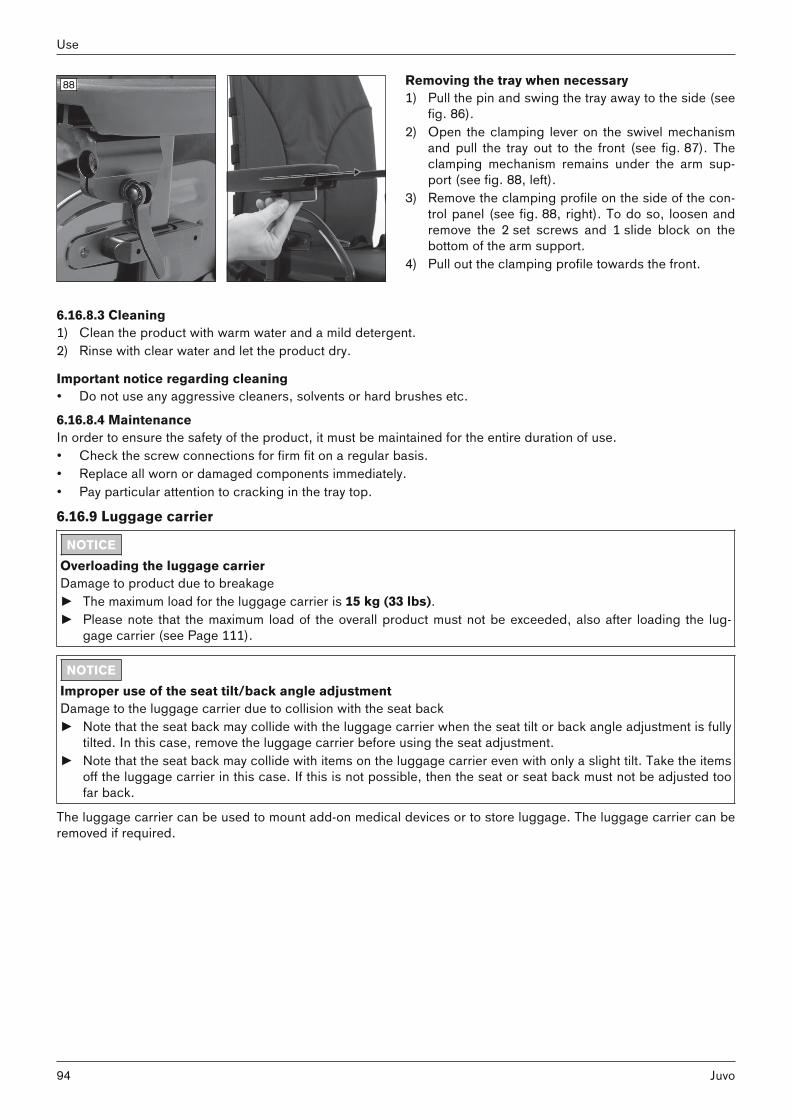
88 Removing the tray when necessary1) Pull the pin and swing the tray away to the side (see
fig. 86).2) Open the clamping lever on the swivel mechanism
and pull the tray out to the front (see fig. 87). Theclamping mechanism remains under the arm support (see fig. 88, left).
3) Remove the clamping profile on the side of the control panel (see fig. 88, right). To do so, loosen andremove the 2 set screws and 1 slide block on thebottom of the arm support.
4) Pull out the clamping profile towards the front.
6.16.8.3 Cleaning1) Clean the product with warm water and a mild detergent. 2) Rinse with clear water and let the product dry.
Important notice regarding cleaning• Do not use any aggressive cleaners, solvents or hard brushes etc.
6.16.8.4 MaintenanceIn order to ensure the safety of the product, it must be maintained for the entire duration of use.• Check the screw connections for firm fit on a regular basis.• Replace all worn or damaged components immediately.• Pay particular attention to cracking in the tray top.
6.16.9 Luggage carrier
NOTICEOverloading the luggage carrierDamage to product due to breakage► The maximum load for the luggage carrier is 15 kg (33 lbs).► Please note that the maximum load of the overall product must not be exceeded, also after loading the lug
gage carrier (see Page 111).
NOTICEImproper use of the seat tilt/back angle adjustmentDamage to the luggage carrier due to collision with the seat back► Note that the seat back may collide with the luggage carrier when the seat tilt or back angle adjustment is fully
tilted. In this case, remove the luggage carrier before using the seat adjustment.► Note that the seat back may collide with items on the luggage carrier even with only a slight tilt. Take the items
off the luggage carrier in this case. If this is not possible, then the seat or seat back must not be adjusted toofar back.
The luggage carrier can be used to mount add-on medical devices or to store luggage. The luggage carrier can beremoved if required.
94
Use
Juvo

89 Removing the luggage carrier1) Pull out the release bolt under the tray (see fig. 89,
item 1).2) Slightly lift the luggage carrier and take it off the
support bar (see fig. 89, item 2).Putting on the luggage carrier1) Slightly lift the luggage carrier and set it onto the
support bar (see fig. 89, item 2).2) Push the luggage carrier down until the release bolt
(see fig. 89, item 1) engages.
6.16.10 Curb climbing assistThe curb climbing assist makes it possible to overcome curbs and steps with a maximum height of 100 mm (4"). INFORMATION: Deviating values for other wheel combinations, see the section "Technical data".
90 Using the curb climbing assist> The curb climbing assist must protrude to the front
when driving outdoors. 1) Drive against an obstacle (e.g. a high curb).2) The curb climbing assist lifts the power wheelchair
over the obstacle.3) After crossing the obstacle, the curb climbing assist
returns to the active, forward-facing position.
91 Temporarily deactivating the curb climbing assist> The curb climbing assist can be deactivated when
driving indoors.1) Pull the release button (see fig. 91, item 1).2) Swing the curb climbing assist back until the lock
ing mechanism engages (see fig. 91, item 2). 3) The curb climbing assist is deactivated.
6.16.11 External power supply
NOTICEOverloading the connectionsPower supply defect► Avoid using all connections at full capacity at the same time. ► For example, if you are charging an oxygen unit on the 12 V connection, you should not charge a tablet PC on
the USB connection at the same time.
The external power supply is used to charge or operate external devices such as mobile phones, laptops or oxygenunits. The type of power supply is embossed in the cover cap. The sides can be chosen as desired.
95Juvo
Use

92 Possible connections:USB: The connection can be used to charge or operatedevices with a standard USB battery charger (seefig. 92, item 1). Outputs: 5 V; to 1 A; 5 V to 2.1 A.12 V: The connection can be used to charge or operatedevices with a 12 V motor vehicle power adapter("Cigarette lighter plug"; see fig. 92, item 2). Output:up to 5 A. Power output: maximum 60 W.24 V: The connection can be used to charge or operatedevices with a 24 V motor vehicle power adapter (notillustrated). Output: up to 3 A. Power output: maximum72 W.
6.16.12 Hand heaterThe hand heater with a cover for one or two hands is an option for installation on Ottobock power wheelchairs. The product produces a stream of warm air that increases the temperature in the area of the control panel undercold ambient conditions. Detailed information regarding use, cleaning and maintenance can be found in the included instructions for use.
6.16.13 Overview of other options
INFORMATIONYou can find these and other optional add-on components on the order form and in the accessories catalogue.
The power wheelchair is equipped with additional options:• Splash guard for drive wheels• Splash guard for caster wheels• Joystick top: Tetra fork, STICK S80, softball, ball top, sponge ball• Crutch holder• Folding rearview mirror• Rear marker plate• External horn• Pocket for mobile phone• Beverage holder• Tool kit• Airman pump
6.17 Disassembly and transport6.17.1 Safety instructions
WARNINGImproper transportation in aircraftBurns, explosion or damage to the battery due to failure to observe the rules for transportation ► Follow the rules of the IATA (International Air Transport Association) and the respective airline when trans
porting the power wheelchair in an aircraft. Before checking in the power wheelchair, the automatic circuitbreaker has to be deactivated and the battery connectors must be insulated so they cannot short-circuit.
► Note that those batteries in particular which may leak or will not be transported upright must be removed andpackaged so they cannot leak or short circuit.
► For more information please visit the www.iata.org website. The manufacturer recommends contacting theairline directly before every flight to obtain information regarding special transport regulations.
► Use the SSR (special service request) codes to describe the type of limited mobility if necessary. You canfor example research these on the Internet.
96
Use
Juvo

CAUTIONSecuring the power wheelchair insufficiently during transportCrushing, pinching of body parts due to failure to observe transportation instructions► During transportation in vehicles or aircraft, on lifting platforms or in lifts, turn the control unit of the power
wheelchair off and lock the brake.► The power wheelchair must be secured in accordance with the regulations for the transport device.► During transport in a vehicle, the power wheelchair must be secured sufficiently with cargo straps. Only
attach the cargo straps to the corresponding transportation eyelets and specified tie-down points.
NOTICELifting the power wheelchair incorrectlyDamage to the power wheelchair due to failure to observe transportation instructions► Hoisting devices used for transportation must have a sufficient capacity. For more information about weight,
see the section "Technical data" (see Page 111).► Do not attach the hoisting devices on moveable or adjustable components.► Ensure that the seat is lowered all the way and the backrest is in a vertical position prior to loading and for
transporting the power wheelchair.
6.17.2 Reducing the transportation sizeThe transportation size can be reduced in a few steps to make transporting the product easier.
93 Preparing for transport1) Fold the backrest forward and onto the seat surface
(see Page 23).2) Remove the side panels (see Page 19). Place the
side panel on the seat. 3) Remove the legrests (see Page 22).
94 Preparing for transport1) Fold the backrest forward and onto the seat surface
(see Page 23).2) Remove the side panels (see Page 19). Place the
side panel with control panel on the seat. 3) Remove the legrests (see Page 22).
97Juvo
Use
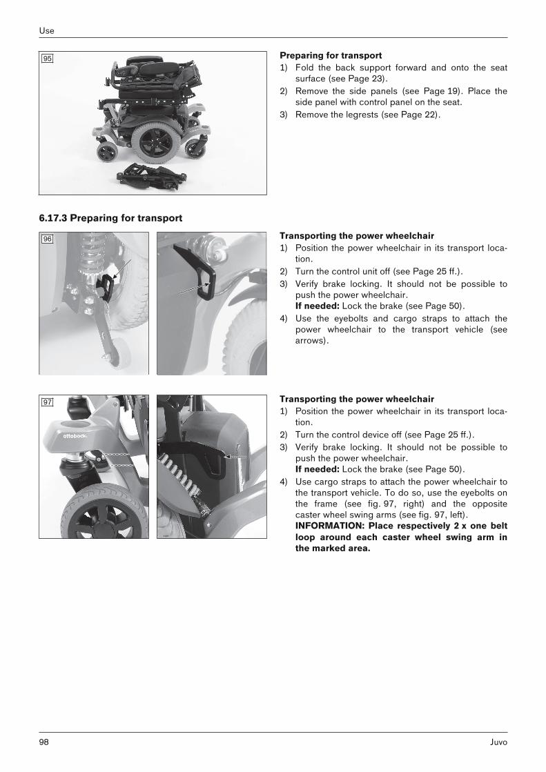
95 Preparing for transport1) Fold the back support forward and onto the seat
surface (see Page 23).2) Remove the side panels (see Page 19). Place the
side panel with control panel on the seat. 3) Remove the legrests (see Page 22).
6.17.3 Preparing for transport
96 Transporting the power wheelchair1) Position the power wheelchair in its transport loca
tion.2) Turn the control unit off (see Page 25 ff.).3) Verify brake locking. It should not be possible to
push the power wheelchair.If needed: Lock the brake (see Page 50).
4) Use the eyebolts and cargo straps to attach thepower wheelchair to the transport vehicle (seearrows).
97 Transporting the power wheelchair1) Position the power wheelchair in its transport loca
tion.2) Turn the control device off (see Page 25 ff.).3) Verify brake locking. It should not be possible to
push the power wheelchair.If needed: Lock the brake (see Page 50).
4) Use cargo straps to attach the power wheelchair tothe transport vehicle. To do so, use the eyebolts onthe frame (see fig. 97, right) and the oppositecaster wheel swing arms (see fig. 97, left).INFORMATION: Place respectively 2 x one beltloop around each caster wheel swing arm inthe marked area.
98
Use
Juvo

6.18 Use in vehicles for transporting persons with reduced mobility
WARNINGUse in vehicles for transporting persons with reduced mobilitySerious injuries in case of accidents due to user error► Always use the seats and restraint systems in the vehicle for transporting persons with reduced mobility first.
This is the only way to ensure optimum protection of passengers in the event of an accident.► If the product is to be used as a seat in a vehicle for transporting persons with reduced mobility, the safety
elements offered by the manufacturer and appropriate personal restraint systems must be used. For moreinformation, please refer to our brochure with the order number 646D158.
► Never transport more than one person in the power wheelchair.► Turn off the control unit after positioning the power wheelchair in the vehicle for transporting persons with
reduced mobility.► Use the power wheelchair in a vehicle for transporting persons with reduced mobility only if the seat is all the
way down and the backrest is in a vertical position.► Observe the limitations regarding installed options (see Page 100).
WARNINGUse of the belt system as a passenger restraint system in vehicles for transporting persons with reducedmobility is forbiddenSerious injuries due to improper handling of the product► Under no circumstances may the belts and positioning aids offered with the product be used as part of a pas
senger restraint system in vehicles for transporting persons with reduced mobility.► Note that the belts and positioning aids offered with the product are only intended to help support the user sit
ting in the product.
The product may be used as a seat in vehicles for transporting persons with reduced mobility.During transport in vehicles for transporting persons with reduced mobility, the product must be sufficientlysecured with attachment straps.
6.18.1 Required accessoriesTo use the power wheelchair as a seat in a vehicle for transporting persons with reduced mobility, additionaloptions have to be mounted (491S00=* anchor point kit). The qualified personnel who fitted the wheelchair canprovide more information.
6.18.2 Using the product in the vehicle
WARNINGPositioning in vehicles for transporting persons with reduced mobility Serious injuries in case of accidents due to user error► Positioning in vehicles for transporting persons with reduced mobility may only be performed by qualified per
sonnel.► Instruct the qualified personnel regarding the mounting points on your product described below.
The product has been tested according to ISO 7176-19.
98 Securing the power wheelchair in the vehicle1) Position the power wheelchair in the vehicle for
transporting persons with reduced mobility. Formore information, refer to section 5 in the brochure"Transporting persons with reduced mobility",order number 646D158.
2) Turn the control device off (see Page 45). 3) Verify brake locking. Engage the brakes if needed
(see Page 50).4) Apply the attachment straps (see below).
99Juvo
Use

99 Applying the attachment straps1) Hook each of the front attachment straps into its
corresponding front anchor point from the outside(see fig. 99, left).
2) Hook the rear attachment straps, 2 x respectively,into the rear anchor points (see fig. 99, right).
3) Tighten the front and rear attachment straps.
100 Securing the power wheelchair in the vehicle1) Position the power wheelchair in the vehicle for
transporting persons with reduced mobility. Formore information, refer to section 5 in the brochure"Transporting persons with reduced mobility",order number 646D158.
2) Turn the control device off (see Page 45). 3) Verify brake locking. Engage the brakes if needed
(see Page 50).4) Apply the attachment straps (see below).
101 Applying the attachment straps1) Hook each of the front attachment straps into its
corresponding front anchor point from the outside(see fig. 101, left).
2) Hook the rear attachment straps, 2 x respectively,into the rear anchor points (see fig. 101, right).
3) Tighten the front and rear attachment straps.
Placement of the restraint system integrated in the vehicleFastening the restraint lap belt of the vehicle for transporting persons with reduced mobility is mandatory.The power wheelchair's lap belt should be used in addition to position the passenger during transportation.The four-point belt can be used in addition to position the passenger during transportation.
6.18.3 Restrictions for use
WARNINGRisk of accidents and injury due to using the product with certain settings and/or installed optionsSevere injury in case of accidents due to options coming loose► Before using the product as a seat in a vehicle for transporting persons with reduced mobility, remove options
that need to be taken off for safe transportation. Please observe the following table.► Stow all dismantled components securely in the vehicle for transporting persons with reduced mobility.► Please note that certain settings on the product exclude the use of the product in a vehicle for transporting
persons with reduced mobility.
100
Use
Juvo

Options* Transportation in avehicle for transporting personswith reduced mobility not possible
Option must beremoved
Secure option onproduct
Tray, swing-away to the side XLap belt with buckle X**Four-way chest strap kit, static X***Luggage carrier for respirator X
* The following list provides an overview. Not all options are installed on all products.** The belt should be used to position the passenger during transportation. Using the personal restraint system isnevertheless required.*** The belt can be used to position the passenger during transportation. Using the personal restraint system isnevertheless required.
Special control (version*) Transportation in avehicle for transporting personswith reduced mobility not possible
Option must beremoved
Secure option onproduct
Sip and puff control (standard control panelincluded)
X
Chin control with mini joystick, powerswing-away
X
Chin control with midi joystick, powerswing-away
X
* The following list provides an overview of all versions of the special control that cannot be used.
6.18.4 Prohibited use
WARNINGImproper use in vehicles for transporting persons with reduced mobilityRisk of serious injury when using the product as a seat ► Please note that certain optional components on the product exclude the use of the product in a vehicle for
transporting persons with reduced mobility.► The product has not been approved by the manufacturer for use as a seat in vehicles for transporting persons
with reduced mobility in combination with a Recaro seat. Please refer to the prohibition symbol on the nameplate (see below).
► In vehicles for transporting persons with reduced mobility, only use the seats installed in the vehicle with thecorresponding personal restraint systems.
► Information on the current status of our measures is available from your specialist dealer.
6.19 Care6.19.1 Safety instructions
CAUTIONIncorrect cleaningInjuries due to product damage, infections/skin irritations due to user error► Water must not come into direct contact with the electronics, motor or batteries under any circumstances dur
ing cleaning. Never use a water jet or high-pressure cleaning apparatus to clean the product.► To avoid contamination with germs, clean seat cushions and back upholstery whenever they get soiled.► Disinfect the product regularly. ► Use a cloth or sponge for cleaning.► To avoid corrosion, do not use any aggressive cleaning agents or solvents.► Check the driving behaviour of the product after cleaning it.
101Juvo
Use

INFORMATIONPiston rods do not require lubrication. They are maintenance-free.
6.19.2 CleaningThe power wheelchair must be cleaned regularly, depending on the amount of use and the degree of soiling.• Clean the control panel, battery charger, armrest and trim components with a damp cloth and mild cleaning
solution.• Use a dry brush to clean the seat and back upholstery as well as the seat cushion.• Use a damp plastic brush to clean the wheels and frame.• Do not use any aggressive cleaners, solvents or hard brushes etc.• Do not spray the product with a pressure washer.
6.19.3 Disinfection1) Thoroughly clean the pads before disinfecting.2) Wipe all parts of the product with a disinfectant.
Important information about disinfecting • Only use colourless water-based disinfectants. Observe the instructions for use provided by the manufacturer.• Prior to disinfection, clean the seat and back padding, control panel and armrests.
7 Maintenance and repair7.1 Safety instructions
WARNINGInsufficient maintenanceSevere user injuries, damage to the product due to failure to observe maintenance intervals► The power wheelchair may only be serviced by qualified personnel trained by the manufacturer. The function
ality and operating safety of the power wheelchair must be verified and a service performed at least 1 x peryear.
► In case of frequent user changes (children and growing youth) or changing clinical pictures, the power wheelchair should be inspected, adjusted and serviced 1 x every six months.
WARNINGFailure to inspect important product featuresSevere user injuries, damage to the product due to maintenance errors► Inspect the seat adjustment features for visible signs of damage at least 1 x per month and ensure all screw
connections are tight.► Maintain sufficient air pressure in the tyres. The correct tyre pressure is printed on the tyre casing and listed
in the section "Technical data".
CAUTIONUncontrolled driving behaviour, unexpected sounds or odoursFalling, tipping, collision with persons or nearby objects due to defects► If any faults, defects or other hazards that can lead to personal injury are detected, the product must be taken
out of service immediately. This includes uncontrolled movements as well as sounds that are unexpected orpreviously not noted or odours that deviate significantly from the state of the product at the time of delivery.
► Please contact your authorised dealer.
7.2 Maintenance• The function of the product should be checked before each use.• The product should not be used if defects are noted. This applies in particular in case of instability of the
product or altered driving characteristics as well as problems with the user's seating position or the stability ofthe seat. Inform the qualified personnel promptly for the rectification of defects.
• This also applies if loose, worn, bent or damaged components, cracks in the frame or broken frame components are identified.
102
Maintenance and repair
Juvo

• Some maintenance tasks and smaller repairs can be carried out to a certain extent by the user at home. Furtherinformation is found in the sections "Maintenance intervals" (see Page 103) and "Repair" (see Page 104).
• Failure to maintain the product can lead to serious or life-threatening injury to the user of the product.• Service and repairs may only be carried out by authorised, qualified personnel or the manufacturer. This will
ensure that only Ottobock spare parts are used for repairs.
7.2.1 Maintenance intervals
Power wheelchair maintenance tasksThe functions described below must be checked by the user or an attendant at the specified intervals:
Component Task Prior toevery use
Weekly Monthly
Check whether wheel mounts are securely fastened XCheck whether wheels rotate freely and without axialrunout
XDrive wheels
Check directional stability of the power wheelchair XCheck whether the fork fits in the adapter without play XCheck whether wheels rotate freely and without axialrunout
XCaster wheels
Check whether the mounting nuts are tight XCheck whether mounting screws are fastened properly XSeat attachmentCheck that seat lock is positioned securely XCheck ratchet mechanism for functionality and firm fit XLeg supportCheck for damage to foot supports XEnsure padding is in perfect condition XCheck the attachment straps for wear X
Padding/straps
Check belt buckle for functionality XCheck air pressure (see tyre sidewall) XCheck for sufficient tread depth (min. 1 mm/0.04") X
Tyres
Check for damage XBatteries Check battery charge level X
Check for external damage XLightsVerify functionality XCheck that the control device is functioning properly(inform qualified personnel of any error messages onthe control panel)
X
Check whether the battery charger is functioning properly (inform qualified personnel of any LED error messages)
X
Electronics
Check plug connections XWhen brake is disengaged: check whether the indicatoron the control panel is flashing
XBrake
When brake is engaged: check braking function by trying to push the chair
X
Visually inspect all moving components and cabling fordamage
XSeat adjustmentfunctions
Check whether screw connections are tight XCheck whether mounting screws are fastened properly XCheck whether screw connections between the armsupport and the control panel are tight
XSide panel andarm support
Check arm support for damage XGas compressionspring or actuator
Visual inspection for scratches and oil leaks on the piston rod
X
Product Check the legibility and completeness of all labels andmarkings on the product
X
103Juvo
Maintenance and repair

Special control maintenance tasks
INFORMATIONEvery special control must be examined by an authorised specialist at least once per year to make sure that it isproperly functional and safe for driving.
The proper functionality of the respective special control must be verified each time before the wheelchair is used.The actions described in the following table should be performed at the specified intervals either by the user or theattendants.
Component Task Prior to every use WeeklyControl device as a whole Verify proper functionality:
verify function of buttons,verify function of specialcontrol components
X
Joystick control Automatic reset to mid-position (neutral position)
X
Wear and tear parts(e.g. tubes of sip and puffcontrol)
Visual inspection X
Mechanical attachment ofthe control device
Check that the movableparts of the control deviceare properly fixed
X
Screw connections Check for firm fit X
7.3 Repair
WARNINGProhibited repairsSevere user injuries, damage to the product due to adjustment and installation errors► Only carry out the repairs described in this section.► Other repairs may not be completed by the product user but only by instructed, qualified personnel.
7.3.1 Replacing a defective bulb
NOTICEUse of incorrect bulbsDamage/melting of the connecting cables due to excess current flow► Note that the LED lighting may only be replaced with original lighting.
The LED lighting is maintenance-free. If repairs are required, the qualified personnel who fitted or delivered thewheelchair can help.
7.3.2 Replacing a batteryBatteries may only be replaced by authorised personnel.
7.4 TroubleshootingINFORMATION
In the event of communication problems in the bus system of the controls, the system triggers an emergency stopand thus prevents any uncontrolled functions.► Note that after every emergency stop, you have to turn the power wheelchair control unit on again.► If the driving function is still not available after turning the control unit on again, activate pushing mode by
releasing the brake.► Inform the qualified personnel immediately.
7.4.1 Types of notifications
WarningA warning indicates a status or malfunction of one or several components of the power wheelchair. The function ofcomponents without errors is not restricted.
104
Maintenance and repair
Juvo

For example, if the connection between the control unit and seat motor is faulty, this error will only be indicated ifthe user attempts to activate the motor. However, the driving function is still available.
ErrorAn error affects one or several functions of the power wheelchair. The power wheelchair and its functions are notfully operational until the fault is resolved.
Structure of an error messageThe control unit display shows both errors in the control system itself as well as errors in electrical components ofthe power wheelchair or errors in the cabling. The error message contains the following information:• Affected module – e.g. JSM = joystick module (control panel); PM = power module (control unit)• Error code (4 characters)• Abbreviated error description
7.4.2 Procedure for warnings and error messages• If a warning or error message appears, the power wheelchair can often no longer be driven. In this case, the
error message must be noted, the control unit switched off and the qualified personnel informed of the errormessage immediately.
• If the error is related to a component which is not currently being used (e.g. to an actuator for adjusting theseat function), the driving function of the power wheelchair is still theoretically usable. An error message simplyappears at regular intervals.
• Nonetheless, the control unit must be switched off for several minutes in this case. If the error message continues to appear after switching on the control unit, the error message must be noted, the control unit switchedoff again and the qualified personnel informed of the error message immediately.
7.4.3 Wheelchair control unit error overviewVR2 control panel
Flashing LED Error/warning Cause Possible corrective actionBattery undervoltage Battery deep discharge
Battery cable malfunctioning or faulty connection to the battery
Charge as soon as possibleCheck the connection to the battery(charge the battery if the connectionis good)
Left motor not connected e.g. defective plug connection, cable break
Check plug connections and cableto left motor
Wiring fault on the leftmotor
e.g. cable break, no connection to battery
Check cable connections to leftmotor; check connection to batteryterminal
Right motor not connected
e.g. defective plug connection, cable break
Check plug connections and cableto right motor
Defective cables on rightmotor
e.g. cable break, no connection to battery
Check cable connections to rightmotor; check connection to batteryterminal
Driving function blockeddue to external factors
Battery charger may beconnected
Disconnect battery charger
Joystick fault Joystick not in home position when the unit isturned on
Move the joystick to the home position before switching the unit on
Controller fault Defective controller Check all connections
Brake release Open brake release Check motor brakesCheck connection to the controller
105Juvo
Maintenance and repair

Flashing LED Error/warning Cause Possible corrective actionBattery overvoltage Voltage too high
Loose battery contactsContinue driving slowlyCheck cabling/plug contacts
Communication errorbetween control panel(joystick) and controller
Defective cable, looseplug connection
Check cabling/plug contacts
TEN° control panel
Symbol Error/warning Cause Possible measureEmergency stop Severe controller /
handheld control unitand/or drive motor malfunction
Check cabling / plug connectionsContact specialist dealer
Joystick warning(Center Joystick)
Joystick not in homeposition when the unitis turned on
Move the joystick to the homeposition before switching the uniton
Defective joystick(Joystick Error)
Message continues tobe displayed despitemoving joystick tocentre position
Contact specialist dealer
Message window forserious errors
Causes of the respective error messages: seefollowing table
Measures for the respective errormessages: see following table
Message window forwarnings(Error messageexamples: see next 2lines)
Causes of the respective warning messages:see following table
Measures for the respective warning messages: see following table
Controller temperaturewarning (lights up red)
Overheating due toexcessive load
Cool down phase
Motor temperaturewarning (lights up red)
Overheating due toexcessive load
Cool down phase
Error and warning messages on the TEN° control panel
Error message Error no. Content Cause Possible measureCenter Joystick See previous tableJoystick Error See previous tableLow Battery (None) Battery undervoltage Battery deep dis
chargeCharge as soon aspossible
High Battery (None) Battery overvoltage Voltage too high Loose battery contacts
Continue drivingslowlyCheck cabling / plugconnections; if errormessage persists,contact specialistdealer
106
Maintenance and repair
Juvo

Error message Error no. Content Cause Possible measureM1 Brake Error 1505 Brake error on left
motorM2 Brake Error 1506 Brake error on right
motor
e.g. defective plugconnection, cablebreakDefective brake
Check plug connections and cable tobrakeIf error persists: contact specialist dealer
M1 Motor Error 3B00 Left motor not connected
M2 Motor Error 3C00 Right motor not connected
e.g. defective plugconnection, cablebreak
Check plug connections and cable tomotor
Inhibit Active 1E01; 1E20; 1E21;1E22; 1E23
Driving functionblocked due toexternal factors
Battery charger maybe connected
Disconnect batterycharger
Brake Lamp Short (None) Short circuit in brakelight electrical circuit
e.g. defective plugconnection, cablebreakDefective brake light
Check plug connections and cable tobrake lightIf error persists: contact specialist dealer
Left Lamp Short 7205 Short circuit in electrical circuit of leftfront/rear light
Right Lamp Short 7209 Short circuit in electrical circuit of rightfront/rear light
e.g. defective plugconnection, cablebreakDefective front/rearlight
Check plug connections and cable tofront/rear lightIf error persists: contact specialist dealer
L Ind Lamp Short 7206 Short circuit in electrical circuit of leftdirection indicator
R Ind Lamp Short 720A Short circuit in electrical circuit of rightdirection indicator
e.g. defective plugconnection, cablebreakDefective directionindicator signal
Check plug connections and cable todirection indicatorIf error persists: contact specialist dealer
L Ind Lamp Failed 7207 Error in electrical circuit of left directionindicator
R Ind Lamp Failed 7208 Error in electrical circuit of right directionindicator
e.g. defective plugconnection, cablebreakDefective bulb
Check plug connections and cable todirection indicatorIf error persists: contact specialist dealer
Over-current (None) Amount of current inan actuator circuittoo great
e.g. defective plugconnection, cablebreakDefective servomotor(actuator) or controller
Check plug connections and cable toservomotor; verifythat actuating drivecan move freelyIf error persists: contact specialist dealer
Overtemp. (Acts) (None) Temperature on actuator circuits on controller too high
e.g. defective plugconnectionsDefective servomotor(actuator)
Cool down phaseCheck plug connections and cable toactuatorIn case of recurrence: contact specialist dealer
Overtemp. (Lamps) (None) Temperature on thelight circuit on thecontroller too high
e.g. defective plugconnectionsDefective lamp
Cool down phaseCheck plug connections and cable tolightIn case of recurrence: contact specialist dealer
107Juvo
Maintenance and repair

Error message Error no. Content Cause Possible measureMemory Error (None) Unspecified memory
error in control modules
e.g. defective plugconnection, cablebreakDefective controlmodule
Contact specialistdealer
PM Memory Error (None) Memory error in controller
e.g. defective plugconnection, cablebreakDefective controller
Check all plug connections and cableson controllerIf error persists: contact specialist dealer
Bad Cable (None) Error on the communication cablesbetween controlmodules
e.g. defective plugconnection, cablebreak
Check all plug connections and cableson the control modules (incl. controller)If error persists: contact specialist dealer
Module Error (None) Error in control modules
e.g. unspecified errorin displayed controlmoduleDisplayed controlmodule defective
Check all plug connections and cablesIf error persists: contact specialist dealer
System Error (None) System error Non-attributable errorin control modules(primarily from third-party providers)
Check all plug connections and cables;disconnect/test anymodules from third-party providers insuccession if applicableIf error persists: contact specialist dealer
SID Detached (None) Special control disconnected
Special control disconnected from LCDmonitor (sip and puffcontrol)Special control connection to LCD monitor defective
Check all plug connections and cablesbetween special control connection andsip and puff control;check programmingparametersIf error persists: contact specialist dealer
1E07 External on/off switchdisconnected fromcontrol panel
Switch Detached
1E08 External profile/modeswitch disconnectedfrom control panel
e.g. defective cableconnection to controlpanelDefective switch orcontrol panel
Check cable connection and switchingfunction of the external switchIf error persists: contact specialist dealer
Gone to Sleep (None) Control unit switchesto sleep mode
Extended inactivitywhile control unit isswitched on
Switch control unitoff/on
Charging (None) Battery charger isconnected
Battery charger isconnected to charging receptacle
Disconnect batterycharger prior to driving
JS Static Timeout (None) Joystick holding timeexceeded
Excessive joystickdeflection detected(control unit stopsdrive system to prevent potential damage to the motors)
Switch control unitoff/onIf error persists:replace control panel/ joystick; contactspecialist dealer
108
Maintenance and repair
Juvo

Error message Error no. Content Cause Possible measureDefective joystick
Orientation Error (None) Orientation error onadvanced stabilitymodule (ASM)
Defective advancedstability module(ASM)
Contact specialistdealer
ASM Disconnected (None) Advanced stabilitymodule (ASM) disconnected from controller
e.g. defective plugconnection, cablebreakDefective advancedstability module(ASM)
Contact specialistdealer
Gyro Disconnected (None) Electronic track stabiliser (gyro module)disconnected fromcontroller
e.g. defective cableconnection to controllerDefective gyro module
Contact specialistdealer
Gyro Prf Active (None) Electronic track stabiliser (gyro module)is activated
Electronic track stabiliser (gyro module)is disrupted by themovement of a different means of transportation (e.g. train,ship) in standbyDefective gyro module
When driving/standing in means of transportation, select the"No Assist" drivingprofile for safety reasons If error persists: contact specialist dealer
1E0D Short circuit onexternal on/off switch
Switch Short
1E0C Short circuit onexternal profile/modeswitch
e.g. defective cableconnection to controlpanelDefective switch orcontrol panel
Check cable connection and switchingfunction of the external switchIf error persists: contact specialist dealer
7.4.4 Attendant control error overviewVR2 attendant control
Flashing LED Error/warning Cause Possible measureControl unit fault Fault in the control unit Read error on the control panel and
take corresponding action (see"Wheelchair control unit error overview" table)
Attendant control fault Defective attendant control Switch off attendant control and turncontrol panel off/on
Joystick error Attendant control joysticknot in home position whenthe unit is turned on
Switch off attendant control and movejoystick to home position beforeswitching the unit onSwitch control panel off/on
Communication errorbetween the attendant control (joystick) and the control panel/controller
Defective cable, loose plugconnection
Check cabling / plug connections
R-Net attendant control
Flashing LED Error/warning Cause Possible measureControl unit fault Fault in the control unit Read error on the control panel and
take corresponding action (see"Wheelchair control unit error overview" table)
109Juvo
Maintenance and repair

Flashing LED Error/warning Cause Possible measureAttendant control fault Defective attendant control Switch off attendant control and turn
control panel off/onJoystick error Attendant control joystick
not in home position whenthe unit is turned on
Switch off attendant control and movejoystick to home position beforeswitching the unit onSwitch control panel off/on
Communication errorbetween the attendant control (joystick) and the control panel/controller
Defective cable, loose plugconnection
Check cabling / plug connections
7.5 Behaviour in case of breakdownsINFORMATION
Note that the following instructions also apply for flat tyres. Independent tyre repairs by the user or an attendantare not intended.
In case of breakdowns, promptly inform the qualified personnel that adapted the product or the manufacturer's service (see inside back cover or back page for addresses). All relevant details have to be provided, such as the typeof power wheelchair, type of breakdown (e.g. problems with the motor) and if possible, the serial number of thepower wheelchair.To get help faster, noting the address and telephone number of the responsible specialist dealer in the fieldprovided on the back of these instructions for use is recommended. This information should be kept on hand,especially when driving outdoors.
8 Disposal8.1 Safety instructions
NOTICEDisposal of batteriesPollution due to incorrect disposal► Observe the information printed on the batteries by the manufacturer.► Note that the batteries may not be disposed of as household waste.
8.2 Disposal informationReturn the product to the specialist dealer for disposal.Please return defective batteries to your specialist dealer when buying new ones. All components of the product must be disposed of properly in accordance with the respective national environmental regulations.
9 Legal informationAll legal conditions are subject to the respective national laws of the country of use and may vary accordingly.
9.1 LiabilityThe manufacturer will only assume liability if the product is used in accordance with the descriptions and instructions provided in this document. The manufacturer will not assume liability for damage caused by disregarding theinformation in this document, particularly due to improper use or unauthorised modification of the product.
9.2 CE conformityThis product meets the requirements of the European Directive 93/42/EEC for medical devices. This product hasbeen classified as a class I device according to the classification criteria outlined in Annex IX of the directive. Thedeclaration of conformity was therefore created by the manufacturer with sole responsibility according to Annex VIIof the directive.The product meets the requirements under the RoHS Directive 2011/65/EU of the European Parliament and of theCouncil of 8 June 2011 on the restriction of the use of certain hazardous substances in electrical and electronicequipment.
110
Disposal
Juvo

9.3 WarrantyFurther information on the warranty terms and conditions can be obtained from the qualified personnel that has fitted this product or the manufacturer's service (see inside back cover for addresses).
9.4 Service lifeExpected service life: 5 years.The design, manufacturing and requirements for the intended use of the product are based on the expected service life. These also include the requirements for maintenance, ensuring effectiveness and the safety of theproduct.Using the product beyond the specified expected service life leads to increased residual risk and should only takeplace subject to the due diligence and deliberations of qualified personnel.If the service life is reached, the user or a responsible attendant should contact the qualified personnel who fittedthe product or the manufacturer's servicing department (see inside rear cover or back page for address). Here theuser can obtain information about known risks and the current options for refurbishing the product.
10 Technical dataINFORMATION
► Much of the technical data below is given in mm. Please note that product settings – unless otherwise specified – cannot be adjusted in the mm range but only in increments of approx. 0.5 cm or 1 cm.
► Note that the values achieved during adjustment may deviate from the values specified below. The deviationcan be ±10 mm and ±2°.
Application class (according to DIN EN 12184)Class A
Application class (according to DIN EN 12184)Class B
Drive typeFront-wheel drive
Drive typeRear-wheel drive
Drive typeMid-wheel drive
Mobility baseSize 1
Mobility baseSize 2
Weight (minimum/maximum)Minimum weight 100 kg (220 lbs)Maximum weight 200 kg (441 lbs)
Weight*Equipped with mobility base 1 + standardseat
from 110 kg (from 242.5 lbs)
Equipped with mobility base 2 + standardseat
from 125 kg (from 275.5 lbs)
Equipped with mobility base 1 + VAS seat from 115 kg (from 253.5 lbs)Equipped with mobility base 2 + VAS seat from 130 kg (from 286.5 lbs)
* The specified weights vary according to the accessories and selected model.
Load capacityMaximum load capacity(User weight + luggage)
See nameplate for precise information
111Juvo
Technical data

Please note: With a standard seat, Junior, the maximum load capacity is reduced to 75 kg (165.3 lbs).
Dimensions – standard seat JuniorEffective seat depth* 340–400 mm (13.4"–15.7")Effective seat width* 340–400 mm (13.4"–15.7")Anterior seat height* 410–570 mm (16.1"–22.4")Lower leg length** 150–540 mm (5.9"–21.2")Back height 370/420/470 mm (14.6"/16.5"/18.5")
* In increments of 20 mm** In increments of 10 mm
Dimensions – standard seat, smallEffective seat depth* 380–460 mm (15"–18.1")Effective seat width* 380–420 mm (15"–16.5")Anterior seat height* 410–570 mm (16.1"–22.4")Lower leg length** 150–540 mm (5.9"–21.2")Back height 450/500/550 mm (17.7"/19.7"/21.6")
* In increments of 20 mm** In increments of 10 mm
Dimensions – standard seat, largeEffective seat depth* 420–500 mm (16.5"–19.7")Effective seat width* 440–480 mm (16.9"–18.9")Anterior seat height* 410–570 mm (16.1"–22.4")Lower leg length** 150–540 mm (5.9"–21.2")Back height 450/500/550 mm (17.7"/19.7"/21.6")
* In increments of 20 mm** In increments of 10 mm
Dimensions – standard seat, XLEffective seat depth* 420–500 mm (16.5"–19.7")Effective seat width* 500–560 mm (19.7"–22")Anterior seat height* 410–570 mm (16.1"–22.4")Lower leg length** 150–540 mm (5.9"–21.2")Back height 450/500/550 mm (17.7"/19.7"/21.6")
* In increments of 20 mm** In increments of 10 mm
Dimensions – VAS seat (all types)Effective seat depth* 380–580 mm (14.6"–22.8")Effective seat width* 380–540 mm (15"–21.3")Anterior seat height** 430–570 mm (16.9"–22.4")Lower leg length*** 150–540 mm (5.9"–21.3")Back height 450/500/550 mm (17.7"/19.7"/21.6")
* Continuous** In increments of 20 mm*** In increments of 10 mm
Dimensions – Recaro® seatEffective seat depth 380–560 mm (15"–22.8")Seat width* Inside: 320–340 mm (12.6"–13.4")
Outside: 450–480 mm (17.7"–18.9")Seat height** 410–570 mm (16.1"–22.4")Lower leg length 280–540 mm (11"–21.2")Back height 620 mm (24.4")
* Inner seat width = effective seat width
112
Technical data
Juvo

** In increments of 20 mm
Dimensions and weights (front-wheel drive; mobility base = size 1)Arm support height (telescoping arm support)
Standard seat: 205–275 mm (8.1"–10.8")Standard seat, Junior: 185–225 mm (7.3"–8.8")VAS seat: 185–255 mm (7.3"–10")
Arm support length (standard) 260 mm (10.2")Foremost point of the side panel (measured to back support)
Minimum: 300 mm (11.8"); maximum: 580 mm (22.8")
Overall width (standard motor/performance or high performance motor)*
596 / 612 mm (23.5" / 24.1")
Overall height (equipped with standardseat)
850–1,110 mm (33.4"–43.7")
Overall height (equipped with VAS seat) 850–1,110 mm (33.4"–43.7")Overall length (without leg support) 908 mm (35.75")Overall length (with leg support) Minimum: 1,050 mm (41.3"); maximum: 1,250 mm (49.2")Transport weights** See "Weight", thereof weight of removable components:
Leg support (standard): approx. 2.2 kg (4.9 lbs)Detachable side panel: approx. 3 kg (6.6 lbs)Leg support (power, with aluminium foot support): approx. 6.5 kg(14.3 lbs)
Minimum turning radius 965 mm (38")Ground clearance 80 mmCaster wheel tyre sizeDrive wheel tyre size
9"/10"14"
* Might be larger due to seat width adjustment. Overall width +180 mm in the assembled state.** Weight of the heaviest component
Dimensions and weights (front-wheel drive; mobility base = size 2)Arm support height (telescoping arm support)
Standard seat: 205–275 mm (8.1"–10.8")Standard seat, Junior: 185–225 mm (7.3"–8.8")VAS seat: 185–255 mm (7.3"–10")
Arm support length (standard) 260 mm (10.2")Foremost point of the side panel (measured to back support)
Minimum: 300 mm (11.8"); maximum: 580 mm (22.8")
Overall width (standard motor/performance or high performance motor)*
626 / 642 mm (24.6" / 25.3")
Overall height (equipped with standardseat)
850–1,110 mm (33.4"–43.7")
Overall height (equipped with VAS seat) 850–1,110 mm (33.4"–43.7")Overall length (without leg support) 968 mm (38.1")Overall length (with leg support) Minimum: 1,050 mm (41.3"); maximum: 1,250 mm (49.2")Transport weights** See "Weight", thereof weight of removable components:
Leg support (standard): approx. 2.2 kg (4.9 lbs)Detachable side panel: approx. 3 kg (6.6 lbs)Leg support (power, with aluminium foot support): approx. 6.5 kg(14.3 lbs)
Minimum turning radius 965 mm (38")Ground clearance 80 mmCaster wheel tyre sizeDrive wheel tyre size
9"/10"14"
* Might be larger due to seat width adjustment. Overall width +180 mm in the assembled state.** Weight of the heaviest component
Dimensions and weights (rear-wheel drive; mobility base = size 1)
113Juvo
Technical data

Dimensions and weights (rear-wheel drive; mobility base = size 1)Arm support height (telescoping arm support)
Standard seat: 205–275 mm (8.1"–10.8")Standard seat, Junior: 185–225 mm (7.3"–8.8")VAS seat: 185–255 mm (7.3"–10")
Arm support length (standard) 260 mm (10.2")Foremost point of the side panel (measured to back support)
Minimum: 300 mm (11.8"); maximum: 580 mm (22.8")
Overall width (standard motor/performance or high performance motor)*
596 / 612 mm (23.5" / 24.1")
Overall height (equipped with standardseat)
850–1,110 mm (33.4"–43.7")
Overall height (equipped with VAS seat) 850–1,110 mm (33.4"–43.7")Overall length (without leg support) 850 mm (33.5")Overall length (with leg support) Minimum: 1,050 mm (41.3"); maximum: 1,250 mm (49.2")Transport weights** See "Weight", thereof weight of removable components:
Leg support (standard): approx. 2.2 kg (4.9 lbs)Detachable side panel: approx. 3 kg (6.6 lbs)Leg support (power, with aluminium foot support): approx. 6.5 kg(14.3 lbs)
Minimum turning radius 965 mm (38")Ground clearance 80 mmCaster wheel tyre sizeDrive wheel tyre size
9"/10"14"
* Might be larger due to seat width adjustment. Overall width +180 mm in the assembled state.** Weight of the heaviest component
Dimensions and weights (rear-wheel drive; mobility base = size 2)Arm support height (telescoping arm support)
Standard seat: 205–275 mm (8.1"–10.8")Standard seat, Junior: 185–225 mm (7.3"–8.8")VAS seat: 185–255 mm (7.3"–10")
Arm support length (standard) 260 mm (10.2")Foremost point of the side panel (measured to back support)
Minimum: 300 mm (11.8"); maximum: 580 mm (22.8")
Overall width (standard motor/performance or high performance motor)*
626 / 642 mm (24.6" / 25.3")
Overall height (equipped with standardseat)
850–1,110 mm (33.4"–43.7")
Overall height (equipped with VAS seat) 850–1,110 mm (33.4"–43.7")Overall length (without leg support) 870 mm (34.3")Overall length (with leg support) Minimum: 1,050 mm (41.3"); maximum: 1,250 mm (49.2")Transport weights** See "Weight", thereof weight of removable components:
Leg support (standard): approx. 2.2 kg (4.9 lbs)Detachable side panel: approx. 3 kg (6.6 lbs)Leg support (power, with aluminium foot support): approx. 6.5 kg(14.3 lbs)
Minimum turning radius 965 mm (38")Ground clearance 80 mmCaster wheel tyre sizeDrive wheel tyre size
9"/10"14"
* Might be larger due to seat width adjustment. Overall width +180 mm in the assembled state.** Weight of the heaviest component
Dimensions and weights (mid-wheel drive; mobility base = size 1)Arm support height (telescoping arm support)
114
Technical data
Juvo

Dimensions and weights (mid-wheel drive; mobility base = size 1)Standard seat: 205–275 mm (8.1"–10.8")Standard seat, Junior: 185–225 mm (7.3"–8.8")VAS seat: 185–255 mm (7.3"–10")
Arm support length (standard) 260 mm (10.2")Foremost point of the side panel (measured to back support)
Minimum: 300 mm (11.8"); maximum: 580 mm (22.8")
Overall width (standard motor/performance or high performance motor)*
596 / 612 mm (23.5" / 24.1")
Overall height (equipped with standardseat)
850–1,110 mm (33.4"–43.7")
Overall height (equipped with VAS seat) 850–1,110 mm (33.4"–43.7")Overall length (without leg support) 908 mm (35.75")Overall length (with leg support) Minimum: 1,050 mm (41.3"); maximum: 1,250 mm (49.2")Transport weights** See "Weight", thereof weight of removable components:
Leg support (standard): approx. 2.2 kg (4.9 lbs)Detachable side panel: approx. 3 kg (6.6 lbs)Leg support (power, with aluminium foot support): approx. 6.5 kg(14.3 lbs)
Minimum turning radius 750 mm (29.5")Ground clearance 80 mm (3")Tyre size front/rear 6"Drive wheel tyre size 14"
* Might be larger due to seat width adjustment. Overall width +180 mm in the assembled state.** Weight of the heaviest component
Dimensions and weights (mid-wheel drive; mobility base = size 2)Arm support height (telescoping arm support)
Standard seat: 205–275 mm (8.1"–10.8")Standard seat, Junior: 185–225 mm (7.3"–8.8")VAS seat: 185–255 mm (7.3"–10")
Arm support length (standard) 260 mm (10.2")Front position of the arm supports (measured to the back support)
Minimum: 300 mm (11.8"); maximum: 580 mm (22.8")
Overall width (standard motor/performance or high performance motor)*
626 / 642 mm (24.6" / 25.3")
Overall height (equipped with standardseat)
850–1,110 mm (33.4"–43.7")
Overall height (equipped with VAS seat) 850–1,110 mm (33.4"–43.7")Overall length (without leg support) 968 mm (38.1")Overall length (with leg support) Minimum: 1,050 mm (41.3"); maximum: 1,250 mm (49.2")Transport weights** See "Weight", thereof weight of removable components:
Leg support (standard): approx. 2.2 kg (4.9 lbs)Detachable side panel: approx. 3 kg (6.6 lbs)Leg support (power, with aluminium foot support): approx. 6.5 kg(14.3 lbs)
Minimum turning radius 750 mm (29.5")Ground clearance 80 mm (3")Tyre size front/rear 6"Drive wheel tyre size 14"
* Might be larger due to seat width adjustment. Overall width +180 mm in the assembled state.** Weight of the heaviest component
Transportation size (storage length x storage width x storage height)Storage length 1100 mm (43.3")Storage width Minimum: 596 mm (23.5"); maximum: 630 mm (24.8")
115Juvo
Technical data

Transportation size (storage length x storage width x storage height)Storage height 500 mm (19.7")
Seat and back adjustmentSeat tilt* Minimum: 0°; maximum: 45°Set pre-tilt of the seat -3°/0°/3°/6°/9° (depending on order)Back angle** Minimum: 90°; maximum: 120°Legrest angle*** Minimum: 90°; maximum: 165°
* Maximum value only with power seat tilt option; specifications do not take set pre-tilt into account** Specifications do not take set pre-tilt into account*** * Maximum value only with power legrest option + manually adjustable legrests; specifications do not take setpre-tilt into account
Power seat functionsBack angle adjustment* Continuously adjustable by up to 30°Seat tilt* Adjustable by up to 45° (with centre of gravity shift)Seat height adjustment* Adjustable by up to 350 mm (13.8"); max. load capacity: 160 kg
(353 lbs)Combined seat height adjustment/seattilt*
Seat height adjustment: adjustable by up to 350 mm (11.8"); seat tilt:adjustable by up to 45°;max. load capacity: 160 kg (353 lbs)
Legrests Continuously adjustable by up to 75°* Depending on equipment
Seat function (manual)Back angle adjustment Adjustable by up to 30°
Seat function (manual)Legrests Adjustable by up to 75°
Drive wheelsTyre type PU tyres
Drive wheelsTyre type Pneumatic tyresTyre pressure Adjust the tyre pressure according to the specifications on the tyre
sidewall to prevent injuries or damage to the product:• 14" drive wheel: 3.5 bar/350 kPa/50 PSI
Caster wheelsTyre type Pneumatic tyresTyre pressure Adjust the tyre pressure according to the specifications on the tyre
sidewall to prevent injuries or damage to the product:• 10" caster wheel: 3.5 bar/350 kPa/50 PSI• 9" caster wheel: 3.5 bar/350 kPa/50 PSI• 9" caster wheel (Impac): 5.2 bar/520 kPA/75 PSI
Caster wheelsTyre type Puncture-proof tyres, filled with polyurethane
Caster wheelsTyre type PU tyres
Driving data (rear-wheel drive/front-wheel drive)Speed* See nameplate for precise information: 6 km/h (3.7 mph); 7.2 km/h
(4.4 mph); 10 km/h (6.2 mph); 14 km/h (8.7 mph)Nominal incline (base model)** 10° (17.5 %)Dynamic stability – uphill*** 10° (17.5 %)Static stability – uphill/downhill 10° (17.5 %)
116
Technical data
Juvo

Driving data (rear-wheel drive/front-wheel drive)Static stability – sideways 10° (17.5 %)Maximum obstacle height With front-wheel drive: 75 mm (3")
With rear-wheel drive: 50 mm (2"); with curb climbing assist: 100 mm(4")
Braking distance (according to DIN EN12184)****
At 6 km/h (3.7 mph): 1,000 mm (39.4") – horizontalAt 7.2 km/h (4.4 mph): 1,200 mm (47.2") – horizontalAt 10 km/h [6.2 mph]: 2,100 mm (82.7") – horizontalAt 14 km/h [8.7 mph]: 3,900 mm (153.5") – horizontal
* The specified speed can vary by ±10%.** The control device and the motors have to be protected against overloading. For this reason, the continuousclimbing ability depends on the overall weight (wheelchair weight + user weight + luggage) as well as the groundconditions, exterior temperature, battery voltage and driving style of the user. In individual cases, the continuousclimbing ability can be significantly lower than the value specified.*** Approved climbing ability with lowered seat functions, upright back support and lowered leg supports.**** The braking distance can be correspondingly longer due to user weight, luggage, installed options and condition of the tyres, and due to weather and surface conditions.
Driving data (mid-wheel drive)Speed* See nameplate for precise information: 6 km/h (3.7 mph); 7.2 km/h
(4.4 mph); 10 km/h (6.2 mph)Nominal incline (base model)** 10° (17.5 %)Dynamic stability – uphill*** 10° (17.5 %)Static stability – uphill/downhill 10° (17.5 %)Static stability – sideways 10° (17.5 %)Maximum obstacle height 65 mm (2.5")Braking distance (according to DIN EN12184:2014)****
At 6 km/h (3.7 mph): 1,000 mm (39.4") – horizontalAt 7.2 km/h (4.4 mph): 1,200 mm (47.2") – horizontalAt 10 km/h [6.2 mph]: 2,100 mm (82.7") – horizontal
* The specified speed can vary by ±10%.** The control device and the motors have to be protected against overloading. For this reason, the continuousclimbing ability depends on the overall weight (wheelchair weight + user weight + luggage) as well as the groundconditions, exterior temperature, battery voltage and driving style of the user. In individual cases, the continuousclimbing ability can be significantly lower than the value specified.*** Approved climbing ability with lowered seat functions, upright back support and lowered leg supports.**** The braking distance can be correspondingly longer due to user weight, luggage, installed options and condition of the tyres, and due to weather and surface conditions.
Range (on level surfaces)*Battery with 53 Ah (C5) / 62 Ah (C20) approx. 26 km (16 miles)
* The specified range was determined under defined conditions according to ISO 7176-4. In practice the rangecan be reduced by up to 50%. For information on this, see the section "Range" in the instructions for use (user).
Range (on level surfaces)*Battery with 63 Ah (C5) / 74 Ah (C20) Approx. 35 km (22 miles)
* The specified range was determined under defined conditions according to ISO 7176-4. In practice the rangecan be reduced by up to 50 %. For information on this, see the section "Range" in the instructions for use (user).
Range (on level surfaces)*Battery with 75 Ah (C5) / 80 Ah (C20) approx. 40 km (24.8 miles)
* The specified range was determined under defined conditions according to ISO 7176-4. In practice the rangecan be reduced by up to 50%. For information on this, see the section "Range" in the instructions for use (user).
Electrical system*IP protection rating (according to DIN EN60529)
IP44
Operating voltage 24 V DCLighting
117Juvo
Technical data

Electrical system*LED front lightLED rear light
24 V, maintenance-free24 V, maintenance-free
Automatic circuit breaker 100 ABattery charger For more information see the included battery charger instructions for
use * The product meets all requirements under ISO 7176-14.
BatteryBatteries 2 x 12 V; 53 Ah (C5) / 62 Ah (C20); AGM; maintenance-free
BatteryBatteries 2 x 12 V; 63 Ah (C5) / 74 Ah (C20); AGM; maintenance-free
BatteryBatteries 2 x 12 V; 63 Ah (C5) / 73 Ah (C20); gel; maintenance-free
BatteryBatteries 2 x 12 V; 75 Ah (C5) / 80 Ah (C20); AGM; maintenance-free
Battery (not delivered by Ottobock)Required specifications 2 x 12 V; up to max. 75 Ah (C5)/ up to max. 92 Ah (C20); gel or AGM;
maintenance-free
Battery charger (not delivered by Ottobock)*Required minimum specifications Maximum current: 10 A; voltage: 220 V
Isolation (class 2) according to IEC 60335-2-29; protection rating:IP21 (Ottobock recommends battery chargers with a protection ratingof IPX4)The battery charger fulfils the normative requirements of EN 12184.This also includes the requirements according to ISO 7176-14 (battery charger with reverse polarity protection; battery charger chargesbatteries to at least 80% within 8 hours; battery charger includesinformation regarding nominal capacity and the possibility of chargingovernight; battery charger indicates that the battery is properly connected)The device fulfils the normative requirements of ISO 7176-21
* For further details, see the instructions for use supplied with the battery charger.
Control deviceModel VR2*Max. output current per motor 90 AForce for operating the joystick on thestandard control panel
1.6 N
* Without power seat functions, without lights
Control deviceModel VR2Max. output current per motor 90 ASeat functions that can be controlled Maximum 2Force for operating the joystick on thestandard control panel
1.6 N
Control deviceModel R-Net (controller in combination with TEN° control panel)Max. output current per motor 90 A (1 x integrated seat function, direct control without actuator mod
ule)Force for operating the joystick on thestandard control panel
1.6 N
118
Technical data
Juvo

Control deviceModel R-Net (controller in combination with TEN° control panel)Max. output current per motor 120 A (seat functions are controlled via the separate actuator module)Force for operating the joystick on thestandard control panel
1.6 N
Control device accessoriesModel R-Net actuator module for controlling additional seat functionsMax. output current per motor 90 A
Allowable environmental conditionsOperating temperature -15 °C to +40 °C (5 °F to +104 °F)Transport and storage temperature -15 °C to +40 °C (5 °F to +104 °F)
Corrosion protectionCorrosion protection Cathodic dip coating / powder coating
11 Appendices11.1 Threshold values for wheelchairs transportable by train
INFORMATION► The products in this series fully satisfy the minimum technical requirements of regulation (EU) No. 1300/2014
regarding train accessibility for people with disabilities. However, not all versions can comply with allthreshold values due to different settings.
► With the help of the table that follows, you or the qualified personnel can take measurements and verify whether the specific product in question meets the threshold values.
Feature Threshold value (according to regulation (EU) No. 1300/2014)Length 1200 mm (47.2"); plus 50 mm (2") for the feetWidth 700 mm (27.6"); plus 50 mm (2") on each side for the hands when
movingSmallest wheels approx. 3" or greater according to the regulation, the smallest wheel
must be able to accommodate a gap measuring 75 mm (3") horizontally and 50 mm (2") vertically
Height max. 1375 mm (54.1"); including a 1.84 m (72.5") large male wheelchair user (95th percentile)
Turning radius 1500 mm (59.1")Maximum weight 300 kg (661 lbs); for wheelchair with occupant, including baggageMaximum obstacle height that can beovercome
50 mm (2")
Ground clearance 60 mm (2.4"); at an upward slope angle of 10°, ground clearancemust measure at least 60 mm (2.4") under the foot rest for going forward at the end of the slope
Maximum inclination angle on which thewheelchair will remain stable
6° (dynamic stability in all directions) 9° (static stability in all directions, also when wheel lock engaged)
119Juvo
Appendices

Juvo120

121Juvo

Juvo122

Kundenservice/Customer Service
EuropeOtto Bock HealthCare Deutschland GmbHMax-Näder-Str. 15 · 37115 Duderstadt · GermanyT +49 5527 848-3433 · F +49 5527 [email protected] · www.ottobock.de
Otto Bock Healthcare Products GmbHBrehmstraße 16 · 1110 Wien · AustriaF +43 1 [email protected] · www.ottobock.at
Otto Bock Adria d.o.o. SarajevoRamiza Salčina 8571000 Sarajevo · Bosnia-HerzegovinaT +387 33 255-405 · F +387 33 [email protected] · www.ottobockadria.com.ba
Otto Bock Bulgaria Ltd.41 Tzar Boris III‘ Blvd. · 1612 Sofia · BulgariaT +359 2 80 57 980 · F +359 2 80 57 [email protected] · www.ottobock.bg
Otto Bock Suisse AGLuzerner Kantonsspital 10 · 6000 Luzern 16 · SuisseT +41 41 455 61 71 · F +41 41 455 61 [email protected] · www.ottobock.ch
Otto Bock ČR s.r.o.Protetická 460 · 33008 Zruč-Senec · Czech RepublicT +420 377825044 · F +420 [email protected] · www.ottobock.cz
Otto Bock Iberica S.A.C/Majada, 1 · 28760 Tres Cantos (Madrid) · SpainT +34 91 8063000 · F +34 91 [email protected] · www.ottobock.es
Otto Bock France SNC4 rue de la Réunion - CS 9001191978 Courtaboeuf Cedex · FranceT +33 1 69188830 · F +33 1 [email protected] · www.ottobock.fr
Otto Bock Healthcare plc32, Parsonage Road · Englefield GreenEgham, Surrey TW20 0LD · United KingdomT +44 1784 744900 · F +44 1784 [email protected] · www.ottobock.co.uk
Otto Bock Hungária Kft.Tatai út 74. · 1135 Budapest · HungaryT +36 1 4511020 · F +36 1 [email protected] · www.ottobock.hu
Otto Bock Adria d.o.o.Dr. Franje Tuđmana 14 ·10431 Sveta Nedelja · CroatiaT +385 1 3361 544 · F +385 1 3365 [email protected] · www.ottobock.hr
Otto Bock Italia Srl UsVia Filippo Turati 5/7 · 40054 Budrio (BO) · ItalyT +39 051 692-4711 · F +39 051 [email protected] · www.ottobock.it
Otto Bock Benelux B.V.Mandenmaker 14 · 5253 RCNieuwkuijk · The NetherlandsT +31 73 5186488 · F +31 73 [email protected] · www.ottobock.nl
Industria Ortopédica Otto Bock Unip. Lda.Av. Miguel Bombarda, 21 - 2º Esq.1050-161 Lisboa · PortugalT +351 21 3535587 · F +351 21 [email protected]
Otto Bock Polska Sp. z o. o.Ulica Koralowa 3 · 61-029 Poznań · PolandT +48 61 6538250 · F +48 61 [email protected] · www.ottobock.pl
Otto Bock Romania srlŞos de Centura Chitila - Mogoşoaia Nr. 3077405 Chitila, Jud. Ilfov · RomaniaT +40 21 4363110 · F +40 21 [email protected] · www.ottobock.ro
OOO Otto Bock Servicep/o Pultikovo, Business Park „Greenwood“,Building 7, 69 km MKAD143441 Moscow Region/Krasnogorskiy RayonRussian FederationT +7 495 564 8360 · F +7 495 564 [email protected] · www.ottobock.ru
Otto Bock Scandinavia ABKoppargatan 3 · Box 623 · 60114 Norrköping · SwedenT +46 11 280600 · F +46 11 [email protected] · www.ottobock.se
Otto Bock Slovakia s.r.o.Röntgenova 26 · 851 01 Bratislava 5 · Slovak RepublicT +421 2 32 78 20 70 · F +421 2 32 78 20 [email protected] · www.ottobock.sk
Otto Bock Sava d.o.o.Industrijska bb · 34000 Kragujevac · Republika SrbijaT +381 34 351 671 · F +381 34 351 [email protected] · www.ottobock.rs
Otto Bock Ortopedi ve Rehabilitasyon Tekniği Ltd. Şti.Mecidiyeköy Mah. Lati Lokum Sok.Meriç Sitesi B Blok No: 30/B34387 Mecidiyeköy-İstanbul · TurkeyT +90 212 3565040 · F +90 212 [email protected] · www.ottobock.com.tr
AfricaOtto Bock Algérie E.U.R.L.32, rue Ahcène Outaleb - Coopérative les MimosasMackle-Ben Aknoun · Alger · DZ AlgérieT +213 21 913863 · F +213 21 [email protected] · www.ottobock.fr
Otto Bock Egypt S.A.E.28 Soliman Abaza St. Mohandessein - Giza · EgyptT +20 2 37606818 · F +20 2 [email protected] · www.ottobock.com.eg
Otto Bock South Africa (Pty) LtdBuilding 3 Thornhill Office Park · 94 Bekker RoadMidrand · Johannesburg · South AfricaT +27 11 564 [email protected]
AmericasOtto Bock Argentina S.A.Av. Belgrano 1477 · CP 1093Ciudad Autônoma de Buenos Aires · ArgentinaT +54 11 5032-8201 / [email protected]
Otto Bock do Brasil Tecnica Ortopédica Ltda.Alameda Maria Tereza, 4036, Bairro Dois CórregosCEP: 13.278-181, Valinhos-São Paulo · Brasil T +55 19 3729 3500 · F +55 19 3269 6061 [email protected] · www.ottobock.com.br
Otto Bock HealthCare Canada5470 Harvester Road Burlington, Ontario, L7L 5N5, CanadaT +1 800 665 3327 · F +1 800 463 [email protected] ·www.ottobock.ca
Oficina Ottobock HabanaCalle 3ra entre 78 y 80.Edificio Jerusalen · Oficina 112 · Calle 3ra.Playa, La Habana. CubaT +53 720 430 69 · +53 720 430 [email protected]
Otto Bock HealthCare Andina Ltda.Calle 138 No 53-38 · Bogotá · ColombiaT +57 1 8619988 · F +57 1 [email protected] · www.ottobock.com.co
Otto Bock de Mexico S.A. de C.V.Prolongación Calle 18 No. 178-ACol. San Pedro de los PinosC.P. 01180 México, D.F. · MexicoT +52 55 5575 0290 · F +52 55 5575 [email protected] · www.ottobock.com.mx
Otto Bock HealthCare LP11501 Alterra Parkway Suite 600Austin, TX 78758 · USAT +1 800 328 4058 · F +1 800 962 [email protected]
Asia/PacificOtto Bock Australia Pty. Ltd.Suite 1.01, Century Corporate Centre62 Norwest BoulevardeBaulkham Hills NSW 2153 · AustraliaT +61 2 8818 2800 · F +61 2 8814 [email protected] · www.ottobock.com.au
Beijing Otto Bock Orthopaedic Industries Co., Ltd.B12E, Universal Business Park10 Jiuxianqiao Road, Chao Yang DistrictBeijing, 100015, P.R. ChinaT +8610 8598 6880 · F +8610 8598 [email protected]
Otto Bock Asia Pacific Ltd.Unit 1004, 10/F, Greenfield Tower, Concordia Plaza 1 Science Museum Road, Tsim Sha TsuiKowloon, Hong Kong · China T +852 2598 9772 · F +852 2598 7886 [email protected] · www.ottobock.com
Otto Bock HealthCare India Pvt. Ltd.20th Floor, Express TowersNariman Point, Mumbai 400 021 · IndiaT +91 22 2274 5500 / 5501 / [email protected] · www.ottobock.in
Otto Bock Japan K. K.Yokogawa Building 8F, 4-4-44 ShibauraMinato-ku, Tokyo, 108-0023 · JapanT +81 3 3798-2111 · F +81 3 [email protected] · www.ottobock.co.jp
Otto Bock Korea HealthCare Inc.4F Agaworld Building · 1357-74, Seocho-dongSeocho-ku, 137-070 Seoul · KoreaT +82 2 577-3831 · F +82 2 [email protected] · www.ottobockkorea.com
Otto BockSouth East Asia Co., Ltd.Bangkok 10900 · ThailandT +66 2 930 3030F +66 2 930 [email protected]
Other countriesOtto Bock HealthCare GmbHMax-Näder-Straße 15 · 37115 Duderstadt · GermanyT +49 5527 848-1590 · F +49 5527 [email protected] · www.ottobock.com

Template-Version: SB_2016-10-21 · FM483 · SB_210x297
Ihr Fachhändler | Your specialist dealer
Otto Bock Mobility Solutions GmbHLindenstraße 13 · 07426 Königsee-Rottenbach/Germanywww.ottobock.com
© O
ttobo
ck ·
647G
2001
=en-
05-1
802