k-1 vehicle user’s guide volume 1 the k-1 vehicle · rocketplane kistler, inc. document no....
TRANSCRIPT
Rocketplane Kistler, Inc. Document No. K1M-001 Rev. A 4300 Amelia Earhart Ln March 2007Oklahoma City, OK 73159 K-1 Vehicle User’s Guide Volume 1– The K-1 Vehicle
Page i
Rocketplane Kistler, Inc.
MODEL NO: K-1 REPORT NO: K1M-001 Rev. A
DATE: March 30, 2007
K-1 Vehicle User’s GuideVolume 1
The K-1 Vehicle

Rocketplane Kistler, Inc. Document No. K1M-001 Rev. A 4300 Amelia Earhart Ln March 2007Oklahoma City, OK 73159 K-1 Vehicle User’s Guide Volume 1– The K-1 Vehicle
Page ii
REVISION HISTORY REV DATE CHANGE CHANGE
AUTHORITY AFFECTED PAGE(S)
A 03-30-07 Initial Release MD27-001
Rocketplane Kistler, Inc. Document No. K1M-001 Rev. A 4300 Amelia Earhart Ln March 2007Oklahoma City, OK 73159 K-1 Vehicle User’s Guide Volume 1– The K-1 Vehicle
Page iii
FOREWORD Rocketplane Kistler, Inc. (RpK) is preparing to initiate commercial launch services using its fully reusable K-1 launch vehicle. This K-1 Payload User’s Guide provides information to potential customers regarding the K-1 Fully Reusable Space Transportation System, K-1 vehicle performance, mission planning and integration, and launch operations and facilities.
This update includes additional detail on RpK’s Woomera launch site and launch operations. Modifications made to RpK’s launch facilities design to improve the efficiency of vehicle processing have also been incorporated.
This user’s guide will be periodically updated. Additional volumes to this user’s guide, detail the capabilities of the K-1 vehicle utilizing different payload modules to serve customers of various markets. All comments and suggestions for additional information are welcome.
For any clarifications or comments, please contact:
Tad Theno
Rocketplane Kistler
4300 Amelia Earhart Lane
Oklahoma City, OK 73159
1-877-238-0057 x105
Website: www.kistleraerospace.com
Electronic Copies of the K-1 User’s Guide may be obtained from the Rocketplane Kistler website at http://www.kistleraerospace.com. Hardcopies are also available upon request.
© Copyright 2007 Rocketplane Kistler, Inc. All rights reserved.
Rocketplane Kistler, Inc. Document No. K1M-001 Rev. A 4300 Amelia Earhart Ln March 2007Oklahoma City, OK 73159 K-1 Vehicle User’s Guide Volume 1– The K-1 Vehicle
Page iv
TABLE OF CONTENTS REVISION HISTORY .............................................................................................................................. ii
FOREWORD .......................................................................................................................................... iii
TABLE OF CONTENTS ........................................................................................................................ iv
LIST OF FIGURES AND TABLES ........................................................................................................ vi
ABBREVIATIONS AND ACRONYMS .................................................................................................. vii
1. INTRODUCTION ............................................................................................................................. 1 1.1 K-1 Program Overview ............................................................................................................. 1 1.2 Summary of Available Launch Services ................................................................................... 2 1.3 Mission Management ............................................................................................................... 3 1.4 Launch Site Overview .............................................................................................................. 3 1.5 Key Customer Advantages ....................................................................................................... 3
2. K-1 VEHICLE OVERVIEW .............................................................................................................. 4 2.1 Launch Assist Platform ............................................................................................................ 4 2.2 Orbital Vehicle .......................................................................................................................... 5 2.3 Interchangeable Payload and Cargo Modules ......................................................................... 5 2.4 Attitude and Control ................................................................................................................. 5 2.5 Communications....................................................................................................................... 6 2.6 Vehicle Coordinate System ...................................................................................................... 8
3. MISSION INTEGRATION AND LAUNCH OPERATIONS .............................................................. 9 3.1 Mission Design and Analysis ................................................................................................... 9
3.1.1 Organization ................................................................................................................ 9 3.1.2 Mission Scheduling ..................................................................................................... 9 3.1.3 Meetings and Reviews ................................................................................................ 9 3.1.4 Mission Analysis & Design Process .......................................................................... 11 3.1.5 Documentation .......................................................................................................... 11
3.2 Vehicle Integration and Ground Ops ...................................................................................... 13 3.2.1 Vehicle Processing and Integration .......................................................................... 13
3.3 Launch Site ............................................................................................................................ 13 3.4 Launch Vehicle Operations .................................................................................................... 15
3.4.1 Launch Decision Process ......................................................................................... 17 3.5 Post-Launch Reports ............................................................................................................. 17
4. FACILITIES ................................................................................................................................... 18 4.1 Payload Processing Facility ................................................................................................... 18
4.1.1 Highbay Work Area ................................................................................................... 18 4.1.2 Control Rooms .......................................................................................................... 18 4.1.3 Hazardous Processing Area ..................................................................................... 18 4.1.4 Office Space ............................................................................................................. 18 4.1.5 Communications ....................................................................................................... 18 4.1.6 Payload Storage ....................................................................................................... 19
Rocketplane Kistler, Inc. Document No. K1M-001 Rev. A 4300 Amelia Earhart Ln March 2007Oklahoma City, OK 73159 K-1 Vehicle User’s Guide Volume 1– The K-1 Vehicle
Page v
4.1.7 Storage Magazines ................................................................................................... 19 4.2 Launch Control Center ........................................................................................................... 20 4.3 Launch Complex .................................................................................................................... 21
4.3.1 Terminal Room ......................................................................................................... 21 4.3.2 Launch Stand and Erector ........................................................................................ 22
4.4 Customer Facilities ................................................................................................................. 22 4.5 Support Services .................................................................................................................... 22
4.5.1 Transportation ........................................................................................................... 22 4.5.2 Communications ....................................................................................................... 22 4.5.3 Security ..................................................................................................................... 22 4.5.4 Woomera Accommodations ...................................................................................... 23
5. SAFETY ......................................................................................................................................... 24 5.1 Introduction ............................................................................................................................ 24 5.2 Personnel and Procedures ..................................................................................................... 24 5.3 Payload and Support Equipment Design ............................................................................... 24 5.4 Safety Approval Process ........................................................................................................ 24 5.5 Safety Meetings and Reviews ................................................................................................ 24

Rocketplane Kistler, Inc. Document No. K1M-001 Rev. A 4300 Amelia Earhart Ln March 2007Oklahoma City, OK 73159 K-1 Vehicle User’s Guide Volume 1– The K-1 Vehicle
Page vi
LIST OF FIGURES AND TABLES Figure 2-1 K-1 Vehicle Profile ................................................................................................................ 4 Figure 2-2 Launch Assist Platform Overview ......................................................................................... 6 Figure 2-3 Orbital Vehicle Overview ...................................................................................................... 7 Figure 2-4 K-1 Vehicle Coordinate System ............................................................................................ 8 Figure 3-1 Mission Management Organization ...................................................................................... 9 Figure 3-2 Typical New Satellite Deployment Mission Schedule ......................................................... 10 Figure 3-3 K-1 Launch Services .......................................................................................................... 11 Figure 3-4 Australia Flight Corridors .................................................................................................... 14 Figure 3-5 Spaceport Woomera ........................................................................................................... 14 Figure 3-6 Launch Vehicle Process Flow ............................................................................................ 15 Figure 3-7 Launch Process Flow Time for Satellite Deployment Mission ............................................ 16 Figure 3-8 Launch Decision Relationships .......................................................................................... 17 Figure 4-1 Payload Processing Facility ................................................................................................ 20 Figure 4-2 Vehicle Processing Facility and Payload Processing Facility ............................................. 21 Figure 4-3 K-1 Launch Complex Overview .......................................................................................... 21 Figure 4-4 Launch Stand Elements ..................................................................................................... 22
Table 1-1 K-1 Program Team ................................................................................................................ 1 Table 3-1 Program Meetings and Reviews for a New Mission ............................................................ 11 Table 3-2 Interface Control Document ................................................................................................. 12 Table 3-3 Launch Operations Plan ...................................................................................................... 13 Table 3-4 Flight Azimuths and Inclination ............................................................................................ 14 Table 4-1 Woomera Accommodations ................................................................................................. 23
Rocketplane Kistler, Inc. Document No. K1M-001 Rev. A 4300 Amelia Earhart Ln March 2007Oklahoma City, OK 73159 K-1 Vehicle User’s Guide Volume 1– The K-1 Vehicle
Page vii
ABBREVIATIONS AND ACRONYMS ACS Attitude Control System amp ampere ATP Authority to Proceed AWG American wire gauge °C degree Centigrade CCP Contamination Control Plan cm centimeter CM cargo module(s) dB decibel deg degree DFO (Kistler Woomera) Director of Flight Operations EMC electromagnetic compatibility EMI electromagnetic interference EPM Extended Payload Module °F degree Fahrenheit FAA Federal Aviation Administration FPR flight performance reserves ft feet g gravity GEO geosynchronous orbit GHz Gigahertz GN2 gaseous Nitrogen GPS Global Positioning System HPA Hazardous Processing Area hr hour Hz Hertz, cycles per second ICD Interface Control Document in inch INS inertial navigation system ISS International Space Station J-box junction box kg kilogram kHz kilohertz km kilometer kPa kilopascal LAP Launch Assist Platform lbf pounds force lbm pounds mass LCC Launch Control Center LEO low earth orbit LN2 liquid nitrogen LOP Launch Operations Plan LOX liquid oxygen LRR Launch Readiness Review LSRD Launch Services Requirements Document m meter mA miliampere
Rocketplane Kistler, Inc. Document No. K1M-001 Rev. A 4300 Amelia Earhart Ln March 2007Oklahoma City, OK 73159 K-1 Vehicle User’s Guide Volume 1– The K-1 Vehicle
Page viii
MD Mission Director MECO main-engine cutoff mg miligrams MHz megahertz mi mile min minute mm milimeters N newtons nmi nautical mile OMS Orbital Maneuvering System OV Orbital Vehicle Pa Pascal PM payload module(s) PPF Payload Processing Facility psi pounds per square inch Q damping factor RAAN right ascension of ascending node RF radio frequency RMS root mean square RP rocket propellant (kerosene) sec second SE support equipment SMU Subsystem Management Unit SPL Sound Pressure Level SPM Standard Payload Module t time TDRSS Tracking Data Relay Satellite System TV television TVC thrust vector control U.S. United States V volts VHM vehicle health maintenance VMC Vehicle Management Computer VPF Vehicle Processing Facility WPA Woomera Prohibited Area
Rocketplane Kistler, Inc. Document No. K1M-001 Rev. A 4300 Amelia Earhart Ln March 2007Oklahoma City, OK 73159 K-1 Vehicle User’s Guide Volume 1– The K-1 Vehicle
Page 1
1. INTRODUCTION
Rocketplane Kistler (RpK) is developing the world’s first commercial, fully reusable aerospace vehicle. The two stage K-1 vehicle is designed to significantly reduce the cost of reliably delivering payloads to Low Earth Orbit (LEO) and to provide rapid launch response and schedule flexibility. Volume 1 of the User’s Guide describes the K-1 vehicle and RpK’s approach to mission planning and integration, ground and launch operations, and services.
Additional volumes will provide performance, environments and interface information specific to the transport services available for use on the K-1 vehicle.
• Volume 2 covers the satellite payload modules for use in deploying satellites to LEO and HEO.
• Volume 3 describes cargo modules used to supply the International Space Station or other orbital destinations.
• Additional Volumes to Follow.
1.1 K-1 Program Overview
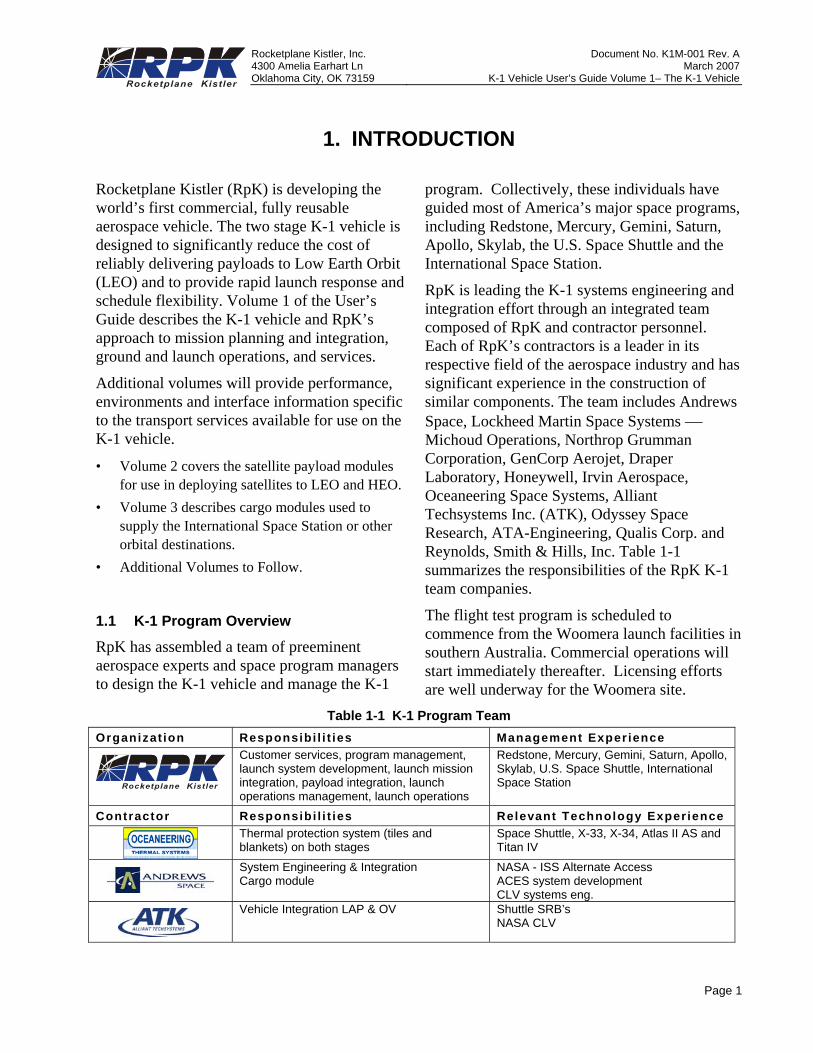
RpK has assembled a team of preeminent aerospace experts and space program managers to design the K-1 vehicle and manage the K-1
program. Collectively, these individuals have guided most of America’s major space programs, including Redstone, Mercury, Gemini, Saturn, Apollo, Skylab, the U.S. Space Shuttle and the International Space Station.
RpK is leading the K-1 systems engineering and integration effort through an integrated team composed of RpK and contractor personnel. Each of RpK’s contractors is a leader in its respective field of the aerospace industry and has significant experience in the construction of similar components. The team includes Andrews Space, Lockheed Martin Space Systems ⎯ Michoud Operations, Northrop Grumman Corporation, GenCorp Aerojet, Draper Laboratory, Honeywell, Irvin Aerospace, Oceaneering Space Systems, Alliant Techsystems Inc. (ATK), Odyssey Space Research, ATA-Engineering, Qualis Corp. and Reynolds, Smith & Hills, Inc. Table 1-1 summarizes the responsibilities of the RpK K-1 team companies.
The flight test program is scheduled to commence from the Woomera launch facilities in southern Australia. Commercial operations will start immediately thereafter. Licensing efforts are well underway for the Woomera site.
Table 1-1 K-1 Program Team Organizat ion Responsibi l i t ies Management Exper ience
Customer services, program management, launch system development, launch mission integration, payload integration, launch operations management, launch operations
Redstone, Mercury, Gemini, Saturn, Apollo, Skylab, U.S. Space Shuttle, International Space Station
Contractor Responsibi l i t ies Relevant Technology Exper ience Thermal protection system (tiles and
blankets) on both stages Space Shuttle, X-33, X-34, Atlas II AS and Titan IV
System Engineering & Integration Cargo module
NASA - ISS Alternate Access ACES system development CLV systems eng.
Vehicle Integration LAP & OV
Shuttle SRB’s NASA CLV
Rocketplane Kistler, Inc. Document No. K1M-001 Rev. A 4300 Amelia Earhart Ln March 2007Oklahoma City, OK 73159 K-1 Vehicle User’s Guide Volume 1– The K-1 Vehicle
Page 2
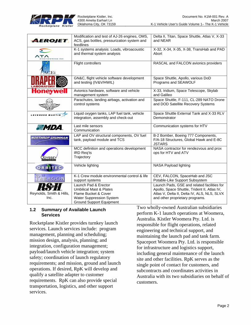
Modification and test of AJ-26 engines, OMS, ACS, gas bottles, pressurization system and feedlines
Delta II, Titan, Space Shuttle, Atlas V, X-33 and NEAR
K-1 systems analysis: Loads, vibroacoustic and thermal system analysis
X-32, X-34, X-35, X-38, TransHab and PAD Abort
Flight controllers RASCAL and FALCON avionics providers
GN&C, flight vehicle software development and testing (IV&V/HWIL)
Space Shuttle, Apollo, various DoD Programs and SEAWOLF
Avionics hardware, software and vehicle management system
X-33, Iridium, Space Telescope, Skylab and Galileo
Parachutes, landing airbags, activation and control systems
Space Shuttle, F-111, CL-289 NATO Drone and DOD Satellite Recovery Systems
Liquid oxygen tanks, LAP fuel tank, vehicle integration, assembly and check-out
Space Shuttle External Tank and X-33 RLV Demonstrator
Last mile sensors Communication
Communication systems for HTV
LAP and OV structural components, OV fuel tank, payload module and TCS
B-2 Bomber, Boeing 777 Components, F/A-18 Structures, Global Hawk and E-8C JSTARS
MCC definition and operations development IRD Req’ts Trajectory
NASA contractor for rendezvous and prox ops for HTV and ATV
Vehicle lighting NASA Payload lighting
K-1 Crew module environmental control & life support systems
CEV, FALCON, SpaceHab and JSC Potable-Like Support Subsystem
Reynolds, Smith & Hills,
Inc.
Launch Pad & Erector Umbilical Mast & Plates Flame Bucket & Cover Water Suppression System Ground Support Equipment
Launch Pads, GSE and related facilities for Apollo, Space Shuttle, Trident II, Atlas IV, Atlas V, Delta II, Delta IV, ALS, NLS, SLVX and other proprietary programs.
1.2 Summary of Available Launch Services
Rocketplane Kistler provides turnkey launch services. Launch services include: program management, planning and scheduling; mission design, analysis, planning; and integration, configuration management; payload/launch vehicle integration; system safety; coordination of launch regulatory requirements; and mission, ground and launch operations. If desired, RpK will develop and qualify a satellite adapter to customer requirements. RpK can also provide special transportation, logistics, and other support services.
Two wholly-owned Australian subsidiaries perform K-1 launch operations at Woomera, Australia. Kistler Woomera Pty. Ltd. is responsible for flight operations, related engineering and technical support, and maintaining the launch pad and tank farm. Spaceport Woomera Pty. Ltd. is responsible for infrastructure and logistics support, including general maintenance of the launch site and other facilities. RpK serves as the single point of contact for customers, and subcontracts and coordinates activities in Australia with its two subsidiaries on behalf of customers.
Rocketplane Kistler, Inc. Document No. K1M-001 Rev. A 4300 Amelia Earhart Ln March 2007Oklahoma City, OK 73159 K-1 Vehicle User’s Guide Volume 1– The K-1 Vehicle
Page 3
1.3 Mission Management
At contract award, RpK assigns an experienced Mission Manager who is responsible for ensuring customer satisfaction. The Mission Manager arranges and directs all necessary resources to successfully complete the launch campaign, and serves as a single-point-of-contact for all mission-related technical and programmatic activities.
Each customer is involved in the development of launch service requirements, payload-to-launch vehicle interfaces, and operations procedures through the establishment of joint integration, mission planning, and operations working groups. For the satellite deployment missions, the critical path to the first launch for a customer is development of a payload-unique adapter. Once this adapter is developed and basic mission design and analyses are complete, the K-1 vehicle can offer rapid call-up launches for delivery of critical on-orbit assets.
1.4 Launch Site Overview
RpK is establishing a launch site for operation of the fleet of K-1 reusable aerospace vehicles at Spaceport Woomera in Australia. Spaceport Woomera is located in Woomera, South Australia, about 470 km (280 miles) north of Adelaide. Test flights and initial commercial operations will be conducted from Spaceport Woomera. The launch site will provide efficient payload processing, integration, and launch operations.
1.5 Key Customer Advantages
Use of the K-1 reusable vehicle to deliver payloads to LEO provides significant advantages to our customers:
• Cost competitive launch services • Reliable missions through repeated use of
proven vehicles • Rapid response launches
• Launch schedule flexibility • Streamlined launch process flow • Highly accurate orbit insertion • Advantageous payment schedules RpK is dedicated to ensuring that each launch campaign results in successful, on-time, accurate delivery of the customer’s payload.
Rocketplane Kistler, Inc. Document No. K1M-001 Rev. A 4300 Amelia Earhart Ln March 2007Oklahoma City, OK 73159 K-1 Vehicle User’s Guide Volume 1– The K-1 Vehicle
Page 4
2. K-1 VEHICLE OVERVIEW
This section provides an overall description of the RpK K-1 reusable aerospace vehicle.
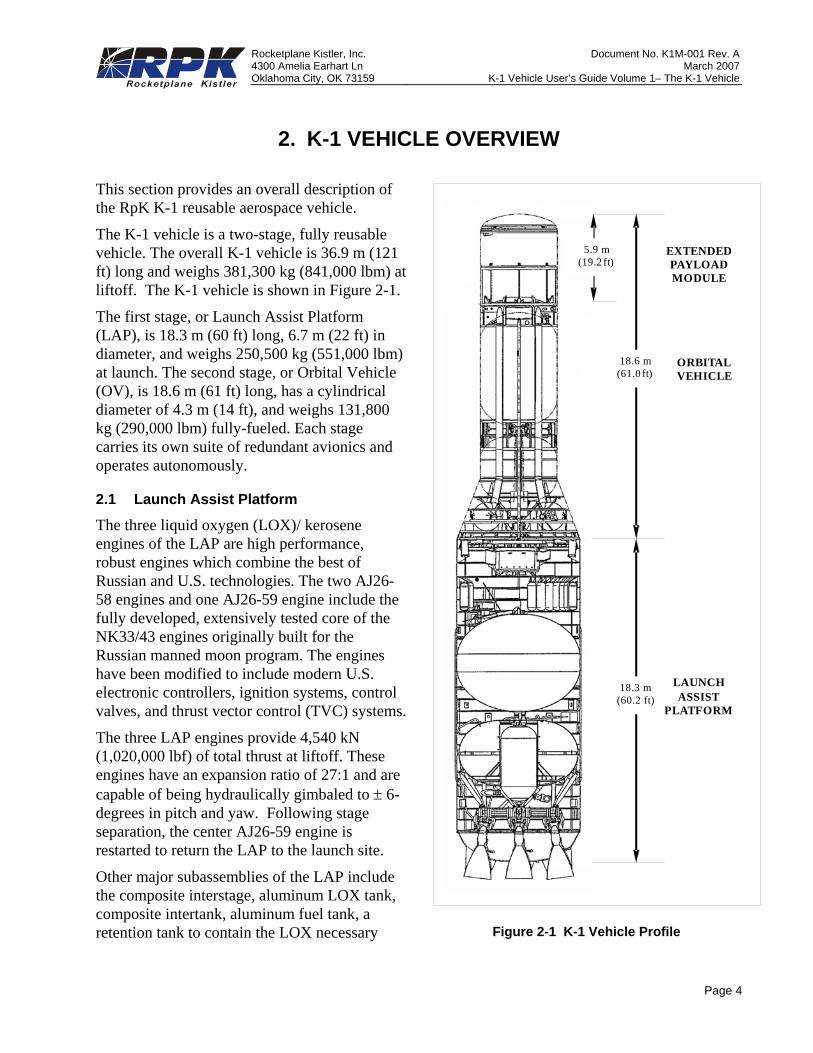
The K-1 vehicle is a two-stage, fully reusable vehicle. The overall K-1 vehicle is 36.9 m (121 ft) long and weighs 381,300 kg (841,000 lbm) at liftoff. The K-1 vehicle is shown in Figure 2-1.
The first stage, or Launch Assist Platform (LAP), is 18.3 m (60 ft) long, 6.7 m (22 ft) in diameter, and weighs 250,500 kg (551,000 lbm) at launch. The second stage, or Orbital Vehicle (OV), is 18.6 m (61 ft) long, has a cylindrical diameter of 4.3 m (14 ft), and weighs 131,800 kg (290,000 lbm) fully-fueled. Each stage carries its own suite of redundant avionics and operates autonomously.
2.1 Launch Assist Platform
The three liquid oxygen (LOX)/ kerosene engines of the LAP are high performance, robust engines which combine the best of Russian and U.S. technologies. The two AJ26-58 engines and one AJ26-59 engine include the fully developed, extensively tested core of the NK33/43 engines originally built for the Russian manned moon program. The engines have been modified to include modern U.S. electronic controllers, ignition systems, control valves, and thrust vector control (TVC) systems.
The three LAP engines provide 4,540 kN (1,020,000 lbf) of total thrust at liftoff. These engines have an expansion ratio of 27:1 and are capable of being hydraulically gimbaled to ± 6-degrees in pitch and yaw. Following stage separation, the center AJ26-59 engine is restarted to return the LAP to the launch site.
Other major subassemblies of the LAP include the composite interstage, aluminum LOX tank, composite intertank, aluminum fuel tank, a retention tank to contain the LOX necessary
EXTENDED PAYLOADMODULE
ORBITALVEHICLE
18.3 m(60.2 ft)
18.6 m(61.0 ft)
5.9 m(19.2 ft)
LAUNCHASSIST
PLATFORM
Figure 2-1 K-1 Vehicle Profile
Rocketplane Kistler, Inc. Document No. K1M-001 Rev. A 4300 Amelia Earhart Ln March 2007Oklahoma City, OK 73159 K-1 Vehicle User’s Guide Volume 1– The K-1 Vehicle
Page 5
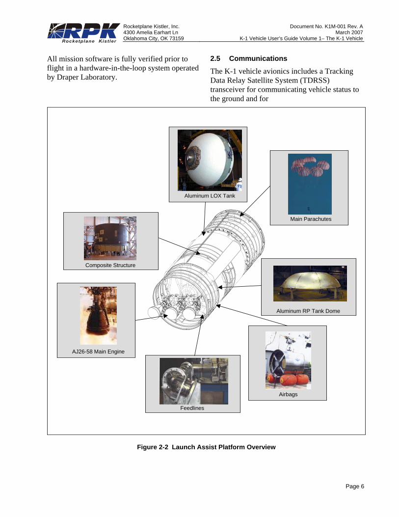
for the flyback to the launch site, and the composite aft skirt. Four hot gas thruster pods provide attitude control during LAP separated flight. Tank pressurization is performed using helium. The avionics system is located in the intertank compartment.
Two drogue parachutes and two clusters of three main parachutes are used to decelerate the LAP for a soft touchdown using four low-pressure airbags.
Figure 2-2 shows an overview of the LAP configuration.
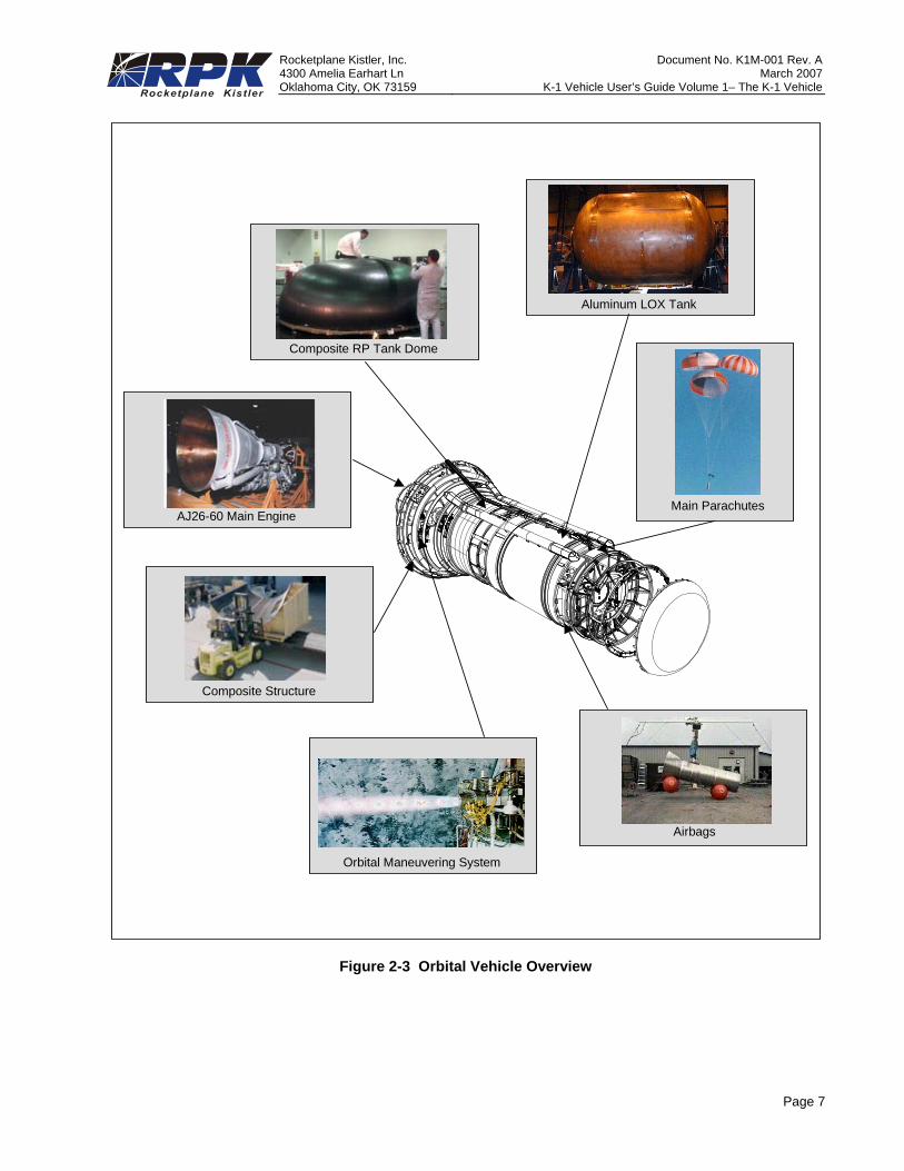
2.2 Orbital Vehicle
The OV uses one AJ26-60 engine for main propulsion. The AJ26-60 provides 1,760 kN (395,000 lbf) vacuum thrust with an expansion ratio of 80:1. The engine is hydraulically gimbaled to provide thrust vector control. After LAP separation, the AJ26-60 engine ignites for a typical 230 second burn to place the vehicle in an elliptical orbit with an apogee at the deployment altitude. Following a coast to apogee the LOX/ethanol Orbital Maneuvering System (OMS) fires to circularize the orbit.
After payload deployment, the OMS fires again to place the OV into a phasing orbit with the correct period for re-entry. Following a second coast phase of up to 22 hours, the vehicle reorients, performs a de-orbit burn with the OMS, and reenters the earth’s atmosphere. The OV flies a guided re-entry trajectory to the launch site. A high-altitude stabilization chute is deployed at Mach 2.5, followed by deployment of a single drogue and three main chutes. The main parachutes decelerate the stage for a soft touchdown using four low-pressure airbags.
Other major subassemblies of the OV include the composite forward skirt, aluminum LOX tank, composite intertank, composite fuel tank and composite flare. Tank pressurization is performed using helium. Four hot gas thruster
pods provide stage attitude control during separated flight. The avionics system is located in the forward compartment behind the payload module.
An overview of the OV configuration is shown in Figure 2-3.
2.3 Interchangeable Payload and Cargo Modules
The K-1 vehicle has interchangeable Payload and Cargo modules to carry satellites or cargo to orbit. Three Payload Module versions to launch satellites are available: Standard Payload Module (SPM), Extended Payload Module (EPM) and Active Dispenser Payload Module (ADPM). Their usage and operation is documented in Volume 2. Two Cargo Modules are available: Pressurized Cargo Module (PCM) and Unpressurized Cargo Module (UCM). Cargo Modules are used to transport cargo to and from the International Space Station (ISS) as well as fly as free flyers for microgravity experiments and manufacture for short periods of time. The Cargo Modules usage and operations are further documented in Volume 3.
2.4 Attitude and Control
Each stage of the K-1 vehicle is completely autonomous from launch to landing. Stage guidance and control are provided by a triple-redundant, fault-tolerant avionics architecture.
Vehicle position, velocity and orientation data are provided by three integrated Global Positioning System (GPS) / Inertial Navigation System (INS) units. Vehicle command and control is managed by the Vehicle Management Computer (VMC) and supported by distributed Subsystem Management Units (SMUs) which are responsible for valve actuation, pyro initiation, and subsystem health monitoring. The main engines and OMS each have their own control units that perform the same functions. Data communications are conducted using a triple-redundant 1553 data bus.
Rocketplane Kistler, Inc. Document No. K1M-001 Rev. A 4300 Amelia Earhart Ln March 2007Oklahoma City, OK 73159 K-1 Vehicle User’s Guide Volume 1– The K-1 Vehicle
Page 6
All mission software is fully verified prior to flight in a hardware-in-the-loop system operated by Draper Laboratory.
2.5 Communications
The K-1 vehicle avionics includes a Tracking Data Relay Satellite System (TDRSS) transceiver for communicating vehicle status to the ground and for
TVC = Thrust Vector Control
INTERSTAGE(FORWARD BODY)
RP TANK
AFT BODY
INTERTANK(MID BODY)
LOX TANK
Aluminum LOX Tank
Composite Structure
AJ26-58 Main Engine
Feedlines
Airbags
Aluminum RP Tank Dome
Main Parachutes
Figure 2-2 Launch Assist Platform Overview
Rocketplane Kistler, Inc. Document No. K1M-001 Rev. A 4300 Amelia Earhart Ln March 2007Oklahoma City, OK 73159 K-1 Vehicle User’s Guide Volume 1– The K-1 Vehicle
Page 7
AJ26-60 Main Engine
Composite Structure
Orbital Maneuvering System
Airbags
Composite RP Tank Dome
Aluminum LOX Tank
Main Parachutes
Figure 2-3 Orbital Vehicle Overview
Rocketplane Kistler, Inc. Document No. K1M-001 Rev. A 4300 Amelia Earhart Ln March 2007Oklahoma City, OK 73159 K-1 Vehicle User’s Guide Volume 1– The K-1 Vehicle
Page 8
updating OV wind data for re-entry targeting. TDRSS is also used to provide the customer with payload deployment data to support ground station acquisition. RpK is responsible for scheduling the use of TDRSS with NASA.
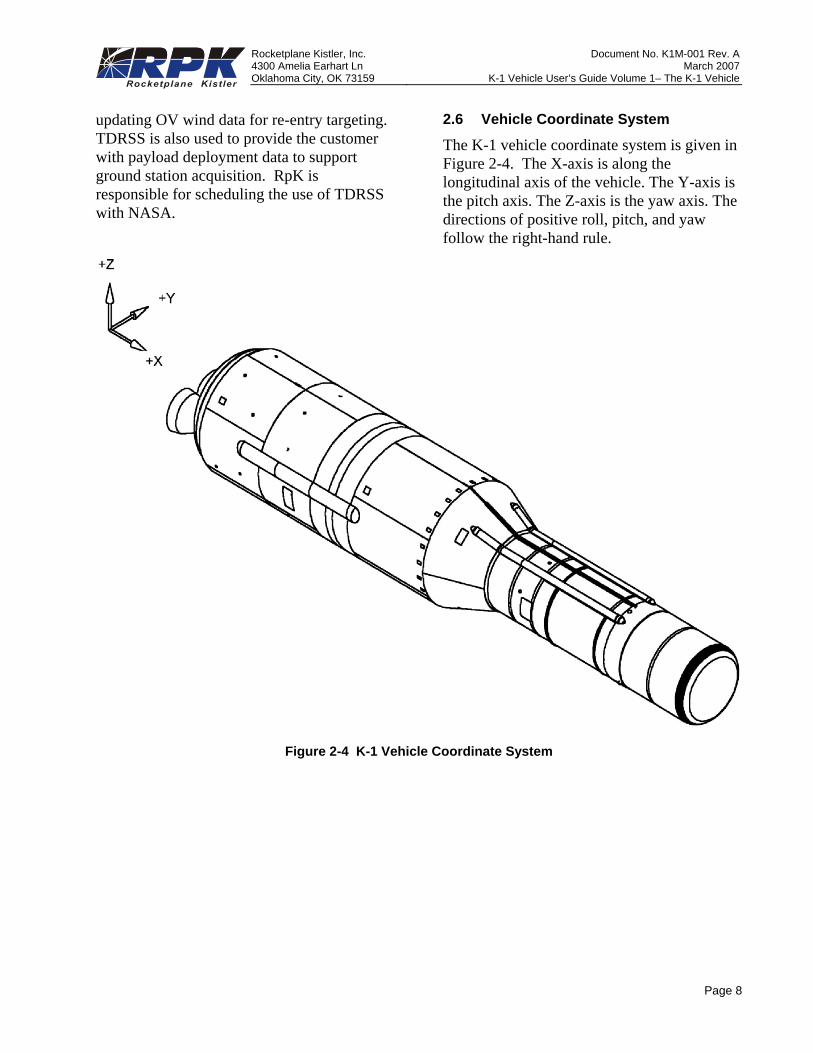
2.6 Vehicle Coordinate System
The K-1 vehicle coordinate system is given in Figure 2-4. The X-axis is along the longitudinal axis of the vehicle. The Y-axis is the pitch axis. The Z-axis is the yaw axis. The directions of positive roll, pitch, and yaw follow the right-hand rule.
Figure 2-4 K-1 Vehicle Coordinate System
Rocketplane Kistler, Inc. Document No. K1M-001 Rev. A 4300 Amelia Earhart Ln March 2007Oklahoma City, OK 73159 K-1 Vehicle User’s Guide Volume 1– The K-1 Vehicle
Page 9
3. MISSION INTEGRATION AND LAUNCH OPERATIONS3.1 Mission Design and Analysis
3.1.1 Organization
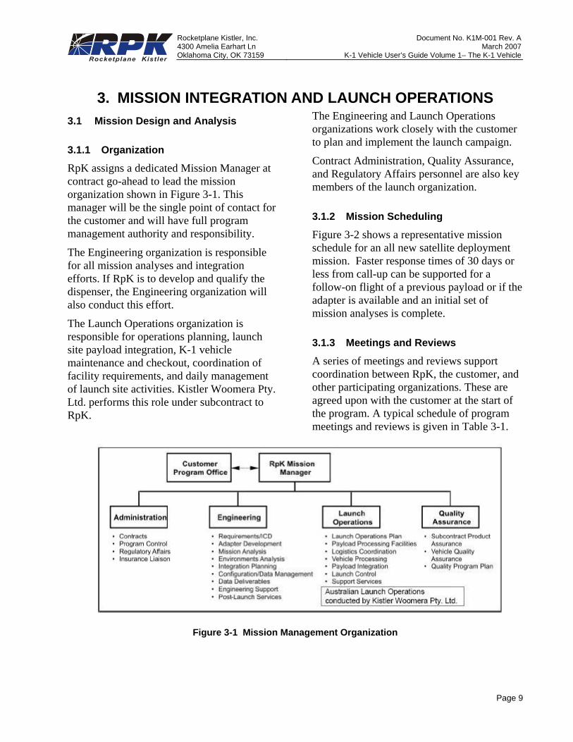
RpK assigns a dedicated Mission Manager at contract go-ahead to lead the mission organization shown in Figure 3-1. This manager will be the single point of contact for the customer and will have full program management authority and responsibility.
The Engineering organization is responsible for all mission analyses and integration efforts. If RpK is to develop and qualify the dispenser, the Engineering organization will also conduct this effort.
The Launch Operations organization is responsible for operations planning, launch site payload integration, K-1 vehicle maintenance and checkout, coordination of facility requirements, and daily management of launch site activities. Kistler Woomera Pty. Ltd. performs this role under subcontract to RpK.
The Engineering and Launch Operations organizations work closely with the customer to plan and implement the launch campaign.
Contract Administration, Quality Assurance, and Regulatory Affairs personnel are also key members of the launch organization.
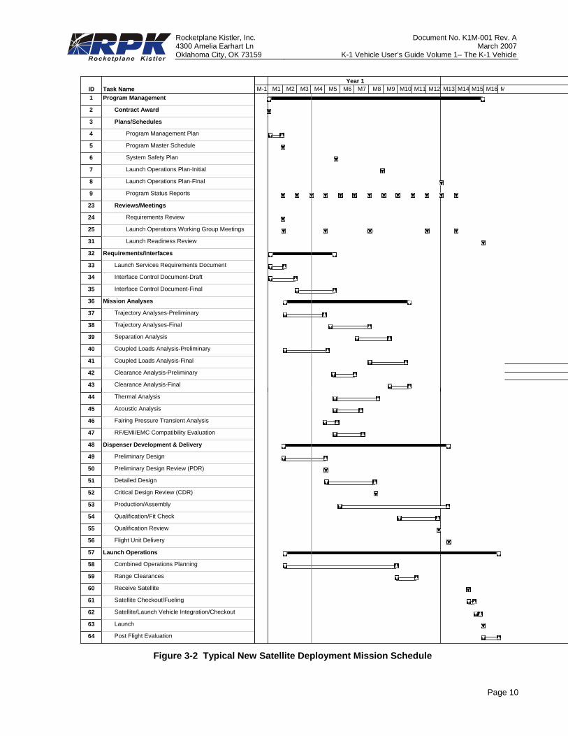
3.1.2 Mission Scheduling
Figure 3-2 shows a representative mission schedule for an all new satellite deployment mission. Faster response times of 30 days or less from call-up can be supported for a follow-on flight of a previous payload or if the adapter is available and an initial set of mission analyses is complete.
3.1.3 Meetings and Reviews
A series of meetings and reviews support coordination between RpK, the customer, and other participating organizations. These are agreed upon with the customer at the start of the program. A typical schedule of program meetings and reviews is given in Table 3-1.
Figure 3-1 Mission Management Organization
Rocketplane Kistler, Inc. Document No. K1M-001 Rev. A 4300 Amelia Earhart Ln March 2007Oklahoma City, OK 73159 K-1 Vehicle User’s Guide Volume 1– The K-1 Vehicle
Page 10
Figure 3-2 Typical New Satellite Deployment Mission Schedule
ID Task Name43 Clearance Analysis-Final
44 Thermal Analysis
45 Acoustic Analysis
46 Fairing Pressure Transient Analysis
47 RF/EMI/EMC Compatibility Evaluation
48 Dispenser Development & Delivery
49 Preliminary Design
50 Preliminary Design Review (PDR)
51 Detailed Design
52 Critical Design Review (CDR)
53 Production/Assembly
54 Qualification/Fit Check
55 Qualification Review
56 Flight Unit Delivery
57 Launch Operations
58 Combined Operations Planning
59 Range Clearances
60 Receive Satellite
61 Satellite Checkout/Fueling
62 Satellite/Launch Vehicle Integration/Checkout
63 Launch
64 Post Flight Evaluation
M-1 M1 M2 M3 M4 M5 M6 M7 M8 M9 M10 M11 M12 M13 M14 M15 M16 MYear 1
ID Task Name1 Program Management
2 Contract Award
3 Plans/Schedules
4 Program Management Plan
5 Program Master Schedule
6 System Safety Plan
7 Launch Operations Plan-Initial
8 Launch Operations Plan-Final
9 Program Status Reports
23 Reviews/Meetings
24 Requirements Review
25 Launch Operations Working Group Meetings
31 Launch Readiness Review
32 Requirements/Interfaces
33 Launch Services Requirements Document
34 Interface Control Document-Draft
35 Interface Control Document-Final
36 Mission Analyses
37 Trajectory Analyses-Preliminary
38 Trajectory Analyses-Final
39 Separation Analysis
40 Coupled Loads Analysis-Preliminary
41 Coupled Loads Analysis-Final
42 Clearance Analysis-Preliminary
43 Clearance Analysis-Final
M-1 M1 M2 M3 M4 M5 M6 M7 M8 M9 M10 M11 M12 M13 M14 M15 M16 MYear 1
Rocketplane Kistler, Inc. Document No. K1M-001 Rev. A 4300 Amelia Earhart Ln March 2007Oklahoma City, OK 73159 K-1 Vehicle User’s Guide Volume 1– The K-1 Vehicle
Page 11
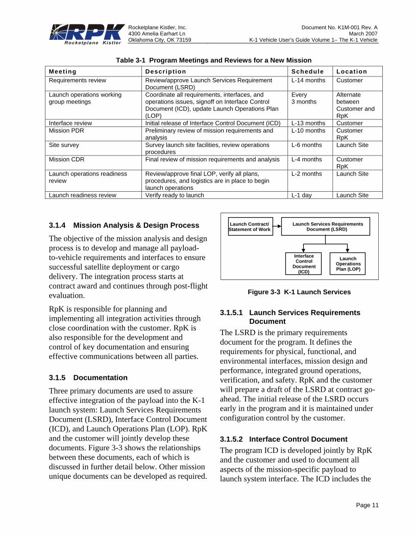
Table 3-1 Program Meetings and Reviews for a New Mission Meet ing Descript ion Schedule Locat ion Requirements review Review/approve Launch Services Requirement
Document (LSRD) L-14 months Customer
Launch operations working group meetings
Coordinate all requirements, interfaces, and operations issues, signoff on Interface Control Document (ICD), update Launch Operations Plan (LOP)
Every 3 months
Alternate between Customer and RpK
Interface review Initial release of Interface Control Document (ICD) L-13 months Customer Mission PDR Preliminary review of mission requirements and
analysis L-10 months Customer
RpK Site survey Survey launch site facilities, review operations
procedures L-6 months Launch Site
Mission CDR Final review of mission requirements and analysis L-4 months Customer RpK
Launch operations readiness review
Review/approve final LOP, verify all plans, procedures, and logistics are in place to begin launch operations
L-2 months Launch Site
Launch readiness review Verify ready to launch L-1 day Launch Site
3.1.4 Mission Analysis & Design Process
The objective of the mission analysis and design process is to develop and manage all payload-to-vehicle requirements and interfaces to ensure successful satellite deployment or cargo delivery. The integration process starts at contract award and continues through post-flight evaluation.
RpK is responsible for planning and implementing all integration activities through close coordination with the customer. RpK is also responsible for the development and control of key documentation and ensuring effective communications between all parties.
3.1.5 Documentation
Three primary documents are used to assure effective integration of the payload into the K-1 launch system: Launch Services Requirements Document (LSRD), Interface Control Document (ICD), and Launch Operations Plan (LOP). RpK and the customer will jointly develop these documents. Figure 3-3 shows the relationships between these documents, each of which is discussed in further detail below. Other mission unique documents can be developed as required.
Launch Contract/Statement of Work
Launch Services RequirementsDocument (LSRD)
InterfaceControl
Document(ICD)
LaunchOperationsPlan (LOP)
Figure 3-3 K-1 Launch Services
3.1.5.1 Launch Services Requirements Document
The LSRD is the primary requirements document for the program. It defines the requirements for physical, functional, and environmental interfaces, mission design and performance, integrated ground operations, verification, and safety. RpK and the customer will prepare a draft of the LSRD at contract go-ahead. The initial release of the LSRD occurs early in the program and it is maintained under configuration control by the customer.
3.1.5.2 Interface Control Document The program ICD is developed jointly by RpK and the customer and used to document all aspects of the mission-specific payload to launch system interface. The ICD includes the
Rocketplane Kistler, Inc. Document No. K1M-001 Rev. A 4300 Amelia Earhart Ln March 2007Oklahoma City, OK 73159 K-1 Vehicle User’s Guide Volume 1– The K-1 Vehicle
Page 12
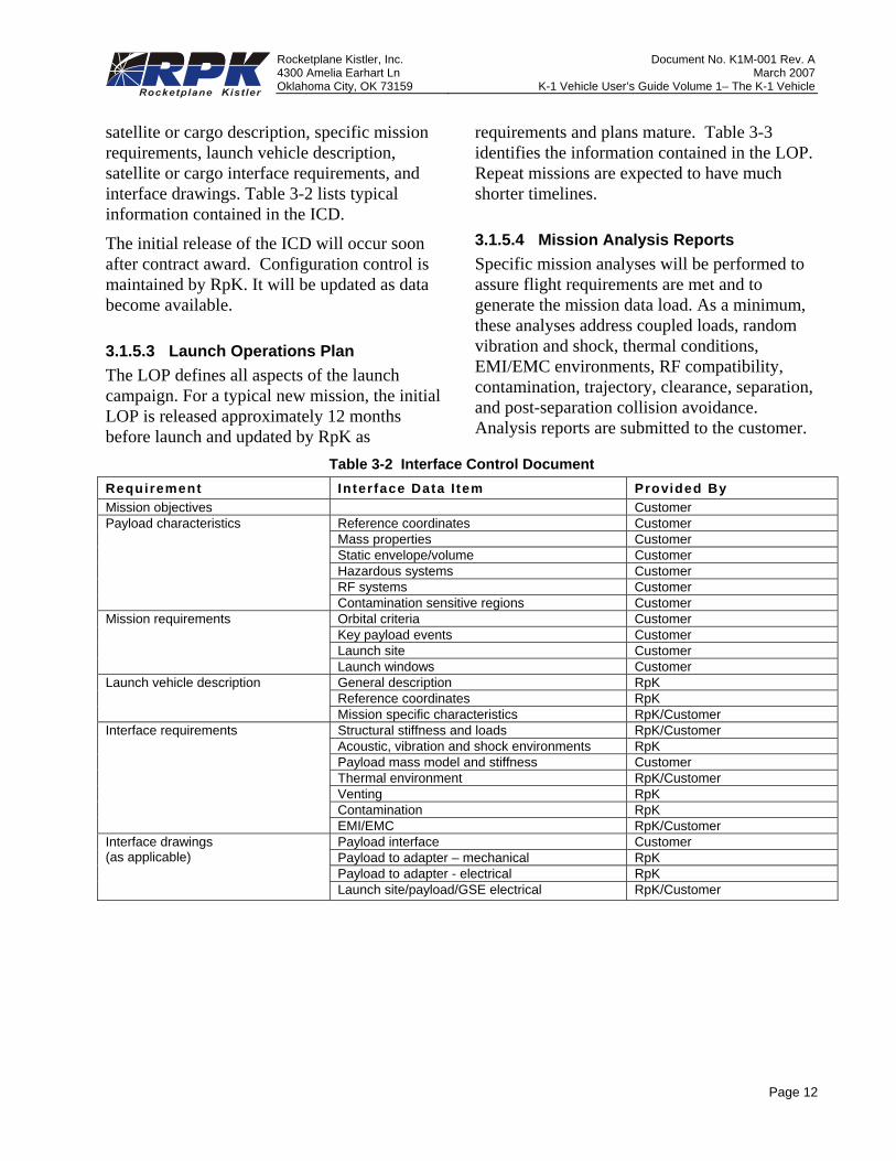
satellite or cargo description, specific mission requirements, launch vehicle description, satellite or cargo interface requirements, and interface drawings. Table 3-2 lists typical information contained in the ICD.
The initial release of the ICD will occur soon after contract award. Configuration control is maintained by RpK. It will be updated as data become available.
3.1.5.3 Launch Operations Plan The LOP defines all aspects of the launch campaign. For a typical new mission, the initial LOP is released approximately 12 months before launch and updated by RpK as
requirements and plans mature. Table 3-3 identifies the information contained in the LOP. Repeat missions are expected to have much shorter timelines.
3.1.5.4 Mission Analysis Reports Specific mission analyses will be performed to assure flight requirements are met and to generate the mission data load. As a minimum, these analyses address coupled loads, random vibration and shock, thermal conditions, EMI/EMC environments, RF compatibility, contamination, trajectory, clearance, separation, and post-separation collision avoidance. Analysis reports are submitted to the customer.
Table 3-2 Interface Control Document Requirement Interface Data I tem Provided By Mission objectives Customer Payload characteristics Reference coordinates Customer
Mass properties Customer Static envelope/volume Customer Hazardous systems Customer RF systems Customer Contamination sensitive regions Customer
Mission requirements Orbital criteria Customer Key payload events Customer Launch site Customer Launch windows Customer
Launch vehicle description General description RpK Reference coordinates RpK Mission specific characteristics RpK/Customer
Interface requirements Structural stiffness and loads RpK/Customer Acoustic, vibration and shock environments RpK Payload mass model and stiffness Customer Thermal environment RpK/Customer Venting RpK Contamination RpK EMI/EMC RpK/Customer
Interface drawings (as applicable)
Payload interface Customer Payload to adapter – mechanical RpK Payload to adapter - electrical RpK Launch site/payload/GSE electrical RpK/Customer
Rocketplane Kistler, Inc. Document No. K1M-001 Rev. A 4300 Amelia Earhart Ln March 2007Oklahoma City, OK 73159 K-1 Vehicle User’s Guide Volume 1– The K-1 Vehicle
Page 13
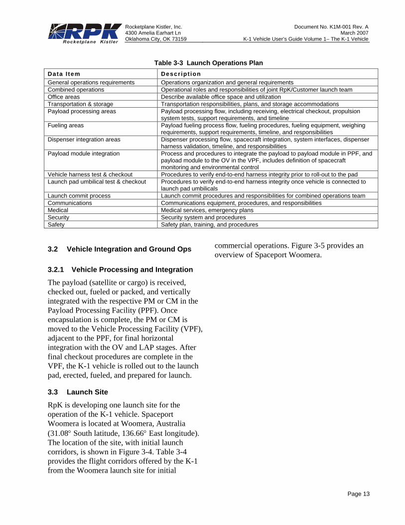
Table 3-3 Launch Operations Plan Data I tem Descript ion General operations requirements Operations organization and general requirements Combined operations Operational roles and responsibilities of joint RpK/Customer launch team Office areas Describe available office space and utilization Transportation & storage Transportation responsibilities, plans, and storage accommodations Payload processing areas Payload processing flow, including receiving, electrical checkout, propulsion
system tests, support requirements, and timeline Fueling areas Payload fueling process flow, fueling procedures, fueling equipment, weighing
requirements, support requirements, timeline, and responsibilities Dispenser integration areas Dispenser processing flow, spacecraft integration, system interfaces, dispenser
harness validation, timeline, and responsibilities Payload module integration Process and procedures to integrate the payload to payload module in PPF, and
payload module to the OV in the VPF, includes definition of spacecraft monitoring and environmental control
Vehicle harness test & checkout Procedures to verify end-to-end harness integrity prior to roll-out to the pad Launch pad umbilical test & checkout Procedures to verify end-to-end harness integrity once vehicle is connected to
launch pad umbilicals Launch commit process Launch commit procedures and responsibilities for combined operations team Communications Communications equipment, procedures, and responsibilities Medical Medical services, emergency plans Security Security system and procedures Safety Safety plan, training, and procedures
3.2 Vehicle Integration and Ground Ops
3.2.1 Vehicle Processing and Integration
The payload (satellite or cargo) is received, checked out, fueled or packed, and vertically integrated with the respective PM or CM in the Payload Processing Facility (PPF). Once encapsulation is complete, the PM or CM is moved to the Vehicle Processing Facility (VPF), adjacent to the PPF, for final horizontal integration with the OV and LAP stages. After final checkout procedures are complete in the VPF, the K-1 vehicle is rolled out to the launch pad, erected, fueled, and prepared for launch.
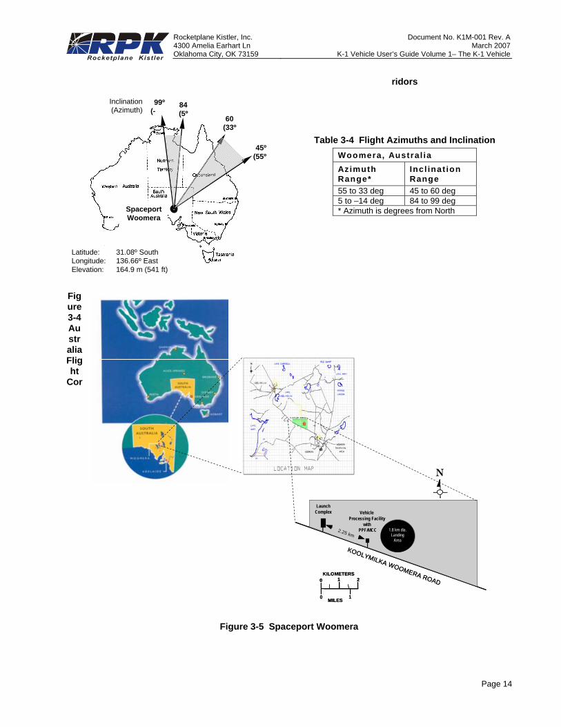
3.3 Launch Site
RpK is developing one launch site for the operation of the K-1 vehicle. Spaceport Woomera is located at Woomera, Australia (31.08° South latitude, 136.66° East longitude). The location of the site, with initial launch corridors, is shown in Figure 3-4. Table 3-4 provides the flight corridors offered by the K-1 from the Woomera launch site for initial
commercial operations. Figure 3-5 provides an overview of Spaceport Woomera.
Rocketplane Kistler, Inc. Document No. K1M-001 Rev. A 4300 Amelia Earhart Ln March 2007Oklahoma City, OK 73159 K-1 Vehicle User’s Guide Volume 1– The K-1 Vehicle
Page 14
Figure 3-4 Australia Flight
Cor
ridors
Table 3-4 Flight Azimuths and Inclination Woomera, Austral ia Azimuth Range*
Incl inat ion Range
55 to 33 deg 45 to 60 deg 5 to –14 deg 84 to 99 deg * Azimuth is degrees from North
Figure 3-5 Spaceport Woomera
45º(55º
60(33º
99º(-
84(5º
SpaceportWoomera
Latitude: 31.08º SouthLongitude: 136.66º EastElevation: 164.9 m (541 ft)
Inclination(Azimuth)
KOOLYMILKA WOOMERA ROAD
1.8 km²Landing
Area
2.25 km
KILOMETERS
MILES
0
0
1
1
2
N
VehicleProcessing Facility
with PPF/MCC
LaunchComplex
1.8 km dia.Landing
Area
KOOLYMILKA WOOMERA ROAD
1.8 km²Landing
Area
2.25 km
KILOMETERS
MILES
0
0
1
1
2
N
VehicleProcessing Facility
with PPF/MCC
LaunchComplex
1.8 km dia.Landing
Area
Rocketplane Kistler, Inc. Document No. K1M-001 Rev. A 4300 Amelia Earhart Ln March 2007Oklahoma City, OK 73159 K-1 Vehicle User’s Guide Volume 1– The K-1 Vehicle
Page 15
3.4 Launch Vehicle Operations
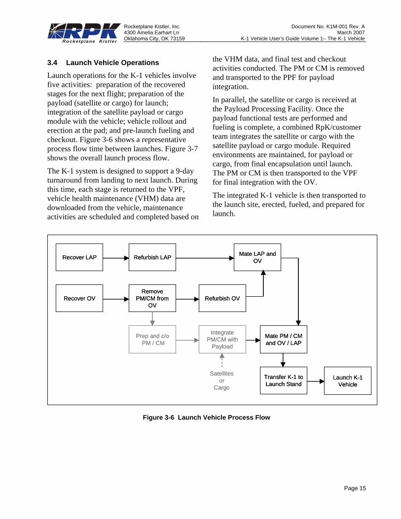
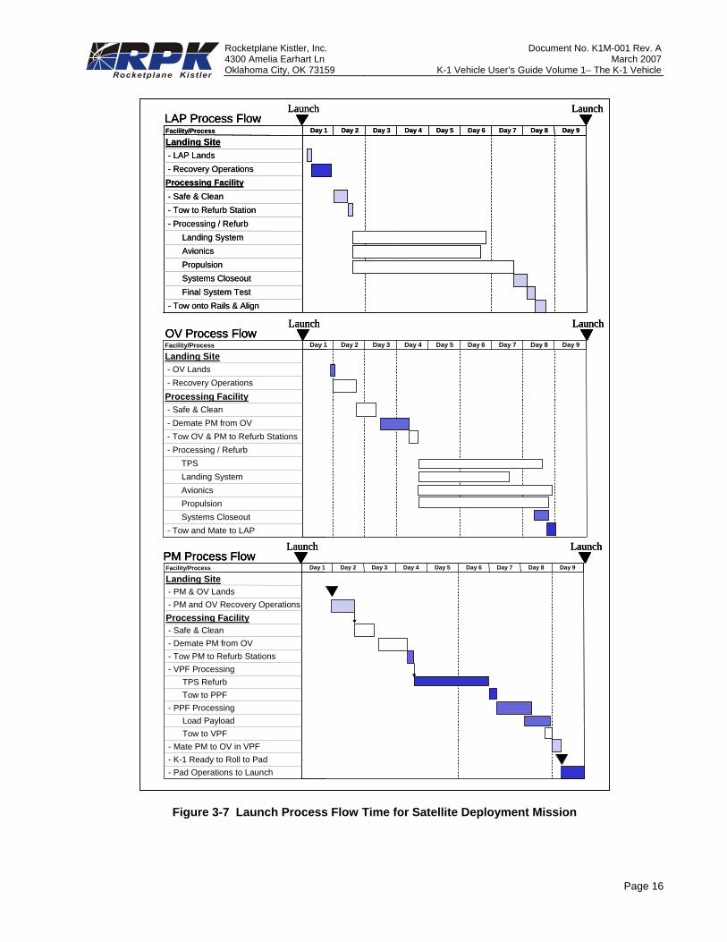
Launch operations for the K-1 vehicles involve five activities: preparation of the recovered stages for the next flight; preparation of the payload (satellite or cargo) for launch; integration of the satellite payload or cargo module with the vehicle; vehicle rollout and erection at the pad; and pre-launch fueling and checkout. Figure 3-6 shows a representative process flow time between launches. Figure 3-7 shows the overall launch process flow.
The K-1 system is designed to support a 9-day turnaround from landing to next launch. During this time, each stage is returned to the VPF, vehicle health maintenance (VHM) data are downloaded from the vehicle, maintenance activities are scheduled and completed based on
the VHM data, and final test and checkout activities conducted. The PM or CM is removed and transported to the PPF for payload integration.
In parallel, the satellite or cargo is received at the Payload Processing Facility. Once the payload functional tests are performed and fueling is complete, a combined RpK/customer team integrates the satellite or cargo with the satellite payload or cargo module. Required environments are maintained, for payload or cargo, from final encapsulation until launch. The PM or CM is then transported to the VPF for final integration with the OV.
The integrated K-1 vehicle is then transported to the launch site, erected, fueled, and prepared for launch.
Recover LAP Refurbish LAP
Recover OVRemove
PM/CM from OV
Prep and c/oPM / CM
Refurbish OV
Mate LAP and OV
Integrate PM/CM with
Payload
Mate PM / CM and OV / LAP
Transfer K-1 to Launch Stand
Launch K-1 Vehicle
Satellitesor
Cargo
Recover LAP Refurbish LAP
Recover OVRemove
PM/CM from OV
Prep and c/oPM / CM
Refurbish OV
Mate LAP and OV
Integrate PM/CM with
Payload
Mate PM / CM and OV / LAP
Transfer K-1 to Launch Stand
Launch K-1 Vehicle
Satellitesor
Cargo
Figure 3-6 Launch Vehicle Process Flow
Rocketplane Kistler, Inc. Document No. K1M-001 Rev. A 4300 Amelia Earhart Ln March 2007Oklahoma City, OK 73159 K-1 Vehicle User’s Guide Volume 1– The K-1 Vehicle
Page 16
Facility/Process
Landing Site- LAP Lands- Recovery OperationsProcessing Facility- Safe & Clean- Tow to Refurb Station- Processing / Refurb
Landing SystemAvionicsPropulsionSystems CloseoutFinal System Test
- Tow onto Rails & Align
Day 1 Day 2 Day 3 Day 4 Day 5 Day 6 Day 7 Day 8 Day 9
Launch LaunchLAP Process Flow
Facility/Process
Landing Site- OV Lands- Recovery OperationsProcessing Facility- Safe & Clean- Demate PM from OV- Tow OV & PM to Refurb Stations- Processing / Refurb
TPSLanding SystemAvionicsPropulsionSystems Closeout
- Tow and Mate to LAP
Day 1 Day 2 Day 3 Day 4 Day 5 Day 6 Day 7 Day 8 Day 9
Launch LaunchOV Process Flow
Facility/Process
Landing Site- PM & OV Lands- PM and OV Recovery OperationsProcessing Facility- Safe & Clean- Demate PM from OV- Tow PM to Refurb Stations- VPF Processing
TPS RefurbTow to PPF
- PPF ProcessingLoad PayloadTow to VPF
- Mate PM to OV in VPF- K-1 Ready to Roll to Pad- Pad Operations to Launch
Day 1 Day 2 Day 3 Day 4 Day 5 Day 6 Day 7 Day 8 Day 9
Launch LaunchPM Process Flow
Facility/Process
Landing Site- LAP Lands- Recovery OperationsProcessing Facility- Safe & Clean- Tow to Refurb Station- Processing / Refurb
Landing SystemAvionicsPropulsionSystems CloseoutFinal System Test
- Tow onto Rails & Align
Day 1 Day 2 Day 3 Day 4 Day 5 Day 6 Day 7 Day 8 Day 9
Launch LaunchLAP Process FlowFacility/Process
Landing Site- LAP Lands- Recovery OperationsProcessing Facility- Safe & Clean- Tow to Refurb Station- Processing / Refurb
Landing SystemAvionicsPropulsionSystems CloseoutFinal System Test
- Tow onto Rails & Align
Day 1 Day 2 Day 3 Day 4 Day 5 Day 6 Day 7 Day 8 Day 9
Launch LaunchLAP Process Flow
Facility/Process
Landing Site- OV Lands- Recovery OperationsProcessing Facility- Safe & Clean- Demate PM from OV- Tow OV & PM to Refurb Stations- Processing / Refurb
TPSLanding SystemAvionicsPropulsionSystems Closeout
- Tow and Mate to LAP
Day 1 Day 2 Day 3 Day 4 Day 5 Day 6 Day 7 Day 8 Day 9
Launch LaunchOV Process FlowFacility/Process
Landing Site- OV Lands- Recovery OperationsProcessing Facility- Safe & Clean- Demate PM from OV- Tow OV & PM to Refurb Stations- Processing / Refurb
TPSLanding SystemAvionicsPropulsionSystems Closeout
- Tow and Mate to LAP
Day 1 Day 2 Day 3 Day 4 Day 5 Day 6 Day 7 Day 8 Day 9Facility/Process
Landing Site- OV Lands- Recovery OperationsProcessing Facility- Safe & Clean- Demate PM from OV- Tow OV & PM to Refurb Stations- Processing / Refurb
TPSLanding SystemAvionicsPropulsionSystems Closeout
- Tow and Mate to LAP
Day 1 Day 2 Day 3 Day 4 Day 5 Day 6 Day 7 Day 8 Day 9
Launch LaunchOV Process Flow
Facility/Process
Landing Site- PM & OV Lands- PM and OV Recovery OperationsProcessing Facility- Safe & Clean- Demate PM from OV- Tow PM to Refurb Stations- VPF Processing
TPS RefurbTow to PPF
- PPF ProcessingLoad PayloadTow to VPF
- Mate PM to OV in VPF- K-1 Ready to Roll to Pad- Pad Operations to Launch
Day 1 Day 2 Day 3 Day 4 Day 5 Day 6 Day 7 Day 8 Day 9
Launch LaunchPM Process FlowFacility/Process
Landing Site- PM & OV Lands- PM and OV Recovery OperationsProcessing Facility- Safe & Clean- Demate PM from OV- Tow PM to Refurb Stations- VPF Processing
TPS RefurbTow to PPF
- PPF ProcessingLoad PayloadTow to VPF
- Mate PM to OV in VPF- K-1 Ready to Roll to Pad- Pad Operations to Launch
Day 1 Day 2 Day 3 Day 4 Day 5 Day 6 Day 7 Day 8 Day 9
Launch LaunchPM Process Flow
Figure 3-7 Launch Process Flow Time for Satellite Deployment Mission
Rocketplane Kistler, Inc. Document No. K1M-001 Rev. A 4300 Amelia Earhart Ln March 2007Oklahoma City, OK 73159 K-1 Vehicle User’s Guide Volume 1– The K-1 Vehicle
Page 17
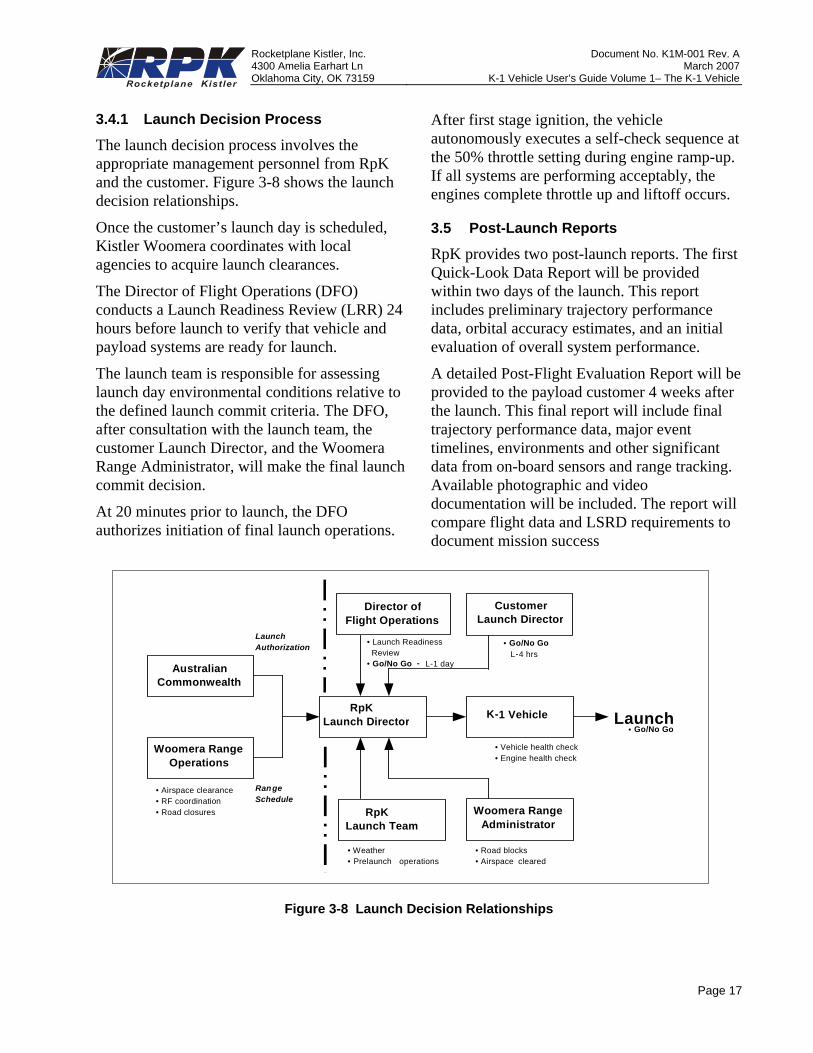
3.4.1 Launch Decision Process
The launch decision process involves the appropriate management personnel from RpK and the customer. Figure 3-8 shows the launch decision relationships.
Once the customer’s launch day is scheduled, Kistler Woomera coordinates with local agencies to acquire launch clearances.
The Director of Flight Operations (DFO) conducts a Launch Readiness Review (LRR) 24 hours before launch to verify that vehicle and payload systems are ready for launch.
The launch team is responsible for assessing launch day environmental conditions relative to the defined launch commit criteria. The DFO, after consultation with the launch team, the customer Launch Director, and the Woomera Range Administrator, will make the final launch commit decision.
At 20 minutes prior to launch, the DFO authorizes initiation of final launch operations.
After first stage ignition, the vehicle autonomously executes a self-check sequence at the 50% throttle setting during engine ramp-up. If all systems are performing acceptably, the engines complete throttle up and liftoff occurs.
3.5 Post-Launch Reports
RpK provides two post-launch reports. The first Quick-Look Data Report will be provided within two days of the launch. This report includes preliminary trajectory performance data, orbital accuracy estimates, and an initial evaluation of overall system performance.
A detailed Post-Flight Evaluation Report will be provided to the payload customer 4 weeks after the launch. This final report will include final trajectory performance data, major event timelines, environments and other significant data from on-board sensors and range tracking. Available photographic and video documentation will be included. The report will compare flight data and LSRD requirements to document mission success
Australian Commonwealth
Woomera Range Operations
Woomera Range Administrator
RpK Launch Director
Director of Flight Operations
K-1 Vehicle
Launch Authorization
Ran ge Schedule • Airspace clearance
• RF coordination • Road closures
Launch
• Go/No Go
• Launch Readiness Review • Go/No Go - L-1 day
Customer Launch Director
• Go/No Go L-4 hrs
RpK Launch Team
• Road blocks • Airspace cleared
• Weather • Prelaunch operations
• Vehicle health check • Engine health check
Figure 3-8 Launch Decision Relationships
Rocketplane Kistler, Inc. Document No. K1M-001 Rev. A 4300 Amelia Earhart Ln March 2007Oklahoma City, OK 73159 K-1 Vehicle User’s Guide Volume 1– The K-1 Vehicle
Page 18
4. FACILITIES4.1 Payload Processing Facility
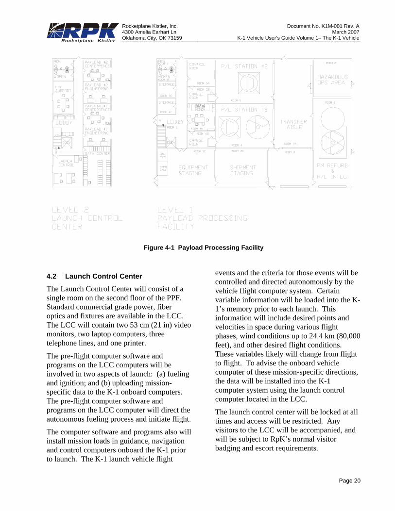
Figure 4-1 shows a layout of the Payload Processing Facility (PPF). Figure 4-2 shows the PPF in relation to the adjacent VPF. The PPF includes two highbay payload processing work areas, two processing control rooms, a highbay payload module processing and hazardous operations area, a master airlock, a support equipment storage area, and the necessary office and personnel facilities. The RpK launch control center is also located in the PPF.
4.1.1 Highbay Work Area
The highbay work area has access to a 10 m (33-ft) overhead crane that can accommodate loads up to 7,500 kg (16,500 lbm). There are two 7.5 m x 10 m (25 ft x 33 ft) work areas, separated by retractable doors. Cleanroom tugs move the payload module and payload. Nitrogen and helium are supplied to the highbay and payload fueling areas at 15,200 kPa (2200 psi). Facility power is provided at 50 Hz at 415 V and is regulated down to standard power to serve U.S. based and international systems including 60Hz at 120V, and 50 Hz at 220-240V. Alternative power accomodations will be made available to meet customer requirements.
4.1.2 Control Rooms
The highbay has two dedicated payload processing control rooms for customer use. A large door is provided in each control room to facilitate installation of customer support equipment. Each control room has a large window for viewing activities in the highbay areas and is also linked to a closed-circuit TV system.
The control rooms also serve as the center for customer on-pad payload operations. Fiber optic control lines lead from the PPF to the terminal room at the pad for remote control of customer GSE during launch operations. The control rooms have direct communications to the launch control room, located in the same building for pre-launch coordination.
4.1.3 Hazardous Processing Area
The HPA is an integral part of the PPF. RpK in cooperation with Kistler Woomera accepts delivery of payloads in cooperation with the Australian Customs Service. To expedite this process payload should typically arrive in Australia without propellant or pyrotechnic devices, or other hazardous materials installed. Once the payload is ready for fueling, it is moved into the HPA where fueling, and installation if pyrotechnics and other hazardous devices or materials will occur. Final integration with the dispenser and the payload module also occurs in this facility. The HPA includes facilities to remove and contain any toxic wastes from fueling operations. RpK can supply propellants under contract.
4.1.4 Office Space
Office accommodations are provided for payload project personnel. This space is conveniently located above the control rooms and has windows to view activities in the highbay.
4.1.5 Communications
The PPF is equipped with closed circuit TV, and audio and video recorders to document and archive daily activities. Local and international telephone and T1 connections are available.
Rocketplane Kistler, Inc. Document No. K1M-001 Rev. A 4300 Amelia Earhart Ln March 2007Oklahoma City, OK 73159 K-1 Vehicle User’s Guide Volume 1– The K-1 Vehicle
Page 19
4.1.6 Payload Storage
Secure storage facility is provided for payloads, dispensers and shipping containers.
4.1.7 Storage Magazines
Concrete bunker-type storage magazines are available for storing ordnance, payload fuels or other hazardous materials.
Rocketplane Kistler, Inc. Document No. K1M-001 Rev. A 4300 Amelia Earhart Ln March 2007Oklahoma City, OK 73159 K-1 Vehicle User’s Guide Volume 1– The K-1 Vehicle
Page 20
Figure 4-1 Payload Processing Facility
4.2 Launch Control Center
The Launch Control Center will consist of a single room on the second floor of the PPF. Standard commercial grade power, fiber optics and fixtures are available in the LCC. The LCC will contain two 53 cm (21 in) video monitors, two laptop computers, three telephone lines, and one printer.
The pre-flight computer software and programs on the LCC computers will be involved in two aspects of launch: (a) fueling and ignition; and (b) uploading mission-specific data to the K-1 onboard computers. The pre-flight computer software and programs on the LCC computer will direct the autonomous fueling process and initiate flight.
The computer software and programs also will install mission loads in guidance, navigation and control computers onboard the K-1 prior to launch. The K-1 launch vehicle flight
events and the criteria for those events will be controlled and directed autonomously by the vehicle flight computer system. Certain variable information will be loaded into the K-1’s memory prior to each launch. This information will include desired points and velocities in space during various flight phases, wind conditions up to 24.4 km (80,000 feet), and other desired flight conditions. These variables likely will change from flight to flight. To advise the onboard vehicle computer of these mission-specific directions, the data will be installed into the K-1 computer system using the launch control computer located in the LCC.
The launch control center will be locked at all times and access will be restricted. Any visitors to the LCC will be accompanied, and will be subject to RpK’s normal visitor badging and escort requirements.
Rocketplane Kistler, Inc. Document No. K1M-001 Rev. A 4300 Amelia Earhart Ln March 2007Oklahoma City, OK 73159 K-1 Vehicle User’s Guide Volume 1– The K-1 Vehicle
Page 21
LOADINGPIT
CR
ANE
FOO
TPR
INT
LOADINGDOCK
62.0m.
40.0
m.
3.9m
.
35.0
m.
23.0m.85.0m.
50.0
m.
VPF PPF(First Floor)
RO
OM
4B
RO
OM
4A
updown
RO
OM
3C
EQ
UIP
ME
NT
STO
RAG
E
ELE
V
FABRIC DOOR
FABRIC DOOR
FABRIC DOOR FABRIC DOOR
SEC
UR
ITYC
ON
TRO
LLED
DO
OR
SEC
UR
ITYC
ON
TRO
LLED
DO
OR
RO
OM
1
RO
OM
3
AIR
LOC
K
RO
OM
4
PA
YLO
AD S
TATIO
N #1
RO
OM
5
PA
YLO
AD
STA
TION
#2
RO
OM
2
TRA
NS
FER
AIS
LE
CO
NTR
OL
RO
OM
#2
RO
OM
5A
CH
ANG
ER
OO
M
RO
OM
5B
ME
N
WO
ME
N
STO
RA
GE
STO
RA
GE
LOBBY
HARDENED DOOR5mwX6mh
VIEWING WINDOW VIEWING WINDOW
EMERG EXITEMERG EXIT
EM
ER
G EX
ITE
ME
RG
EXIT
RO
OM
3B
SH
IPME
NT
STA
GIN
G
FABR
IC D
OO
R5m
wX6m
h
FABRIC DOOR
CO
MM
CAG
E
UTIL
PW
R
RO
OM
3A
RO
OM
6
RO
OM
4C
RO
OM
5C
RO
OM
8
RO
OM
7
PM R
EFU
RB
.&
P/L INTE
GR
ATIO
N
HA
ZAR
DO
US
OP
S AR
EA
HAR
DE
NE
D W
ALL
GA
RM
EN
TS
EMER
G E
XITEM
ERG
EXIT
CO
NTR
OL
RO
OM
#1
Rail to Launch Stand
LOADINGPIT
CR
ANE
FOO
TPR
INT
LOADINGDOCK
62.0m.
40.0
m.
3.9m
.
35.0
m.
23.0m.85.0m.
50.0
m.
VPF PPF(First Floor)
RO
OM
4B
RO
OM
4A
updown
RO
OM
3C
EQ
UIP
ME
NT
STO
RAG
E
ELE
V
FABRIC DOOR
FABRIC DOOR
FABRIC DOOR FABRIC DOOR
SEC
UR
ITYC
ON
TRO
LLED
DO
OR
SEC
UR
ITYC
ON
TRO
LLED
DO
OR
RO
OM
1
RO
OM
3
AIR
LOC
K
RO
OM
4
PA
YLO
AD S
TATIO
N #1
RO
OM
5
PA
YLO
AD
STA
TION
#2
RO
OM
2
TRA
NS
FER
AIS
LE
CO
NTR
OL
RO
OM
#2
RO
OM
5A
CH
ANG
ER
OO
M
RO
OM
5B
ME
N
WO
ME
N
STO
RA
GE
STO
RA
GE
LOBBY
HARDENED DOOR5mwX6mh
VIEWING WINDOW VIEWING WINDOW
EMERG EXITEMERG EXIT
EM
ER
G EX
ITE
ME
RG
EXIT
RO
OM
3B
SH
IPME
NT
STA
GIN
G
FABR
IC D
OO
R5m
wX6m
h
FABRIC DOOR
CO
MM
CAG
E
UTIL
PW
R
RO
OM
3A
RO
OM
6
RO
OM
4C
RO
OM
5C
RO
OM
8
RO
OM
7
PM R
EFU
RB
.&
P/L INTE
GR
ATIO
N
HA
ZAR
DO
US
OP
S AR
EA
HAR
DE
NE
D W
ALL
GA
RM
EN
TS
EMER
G E
XITEM
ERG
EXIT
CO
NTR
OL
RO
OM
#1
Rail to Launch Stand
Figure 4-2 Vehicle Processing Facility and Payload Processing Facility
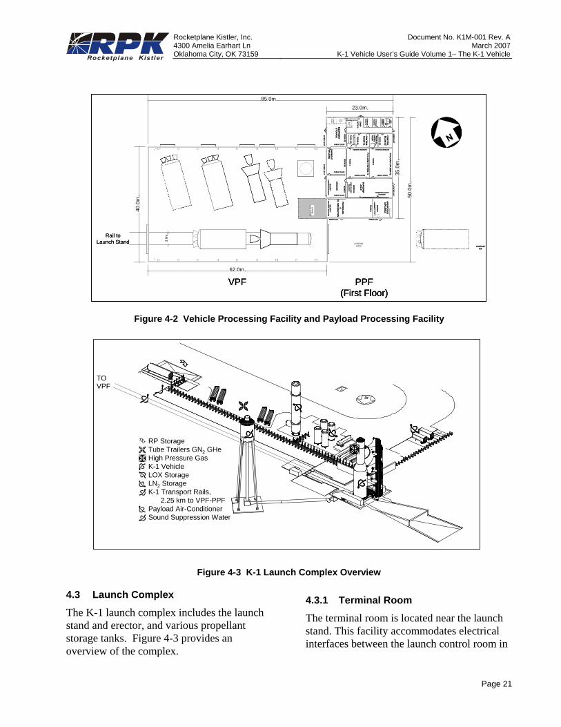
RP StorageTube Trailers GN2 GHeHigh Pressure GasK-1 VehicleLOX StorageLN2 StorageK-1 Transport Rails,
2.25 km to VPF-PPFPayload Air-ConditionerSound Suppression Water
TO VPF
Figure 4-3 K-1 Launch Complex Overview
4.3 Launch Complex
The K-1 launch complex includes the launch stand and erector, and various propellant storage tanks. Figure 4-3 provides an overview of the complex.
4.3.1 Terminal Room
The terminal room is located near the launch stand. This facility accommodates electrical interfaces between the launch control room in
Rocketplane Kistler, Inc. Document No. K1M-001 Rev. A 4300 Amelia Earhart Ln March 2007Oklahoma City, OK 73159 K-1 Vehicle User’s Guide Volume 1– The K-1 Vehicle
Page 22
the PPF and the umbilical mast at the launch stand. Monitoring and control of customer payload GSE is provided through modems to Seimens WCH-08p fiber optic transmitters. Forty-two (42) twisted and shielded pairs of 16 AGW wires run 53 m (174 ft) between the terminal room junction box and the OV payload umbilical interface. Electrical power includes 50 Hz, 415 volt, 30 amp three-phase and 50 Hz, 250 volt, 60 amp single-phase. Six standard equipment racks are allocated for customer GSE.
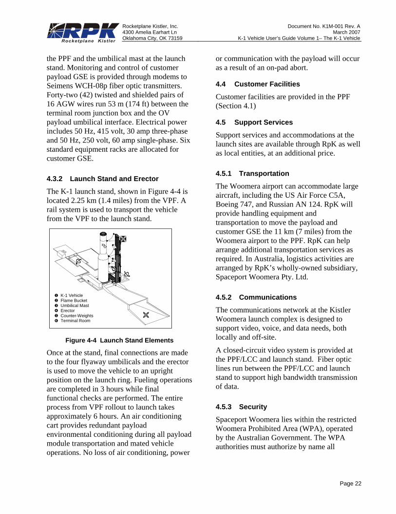
4.3.2 Launch Stand and Erector
The K-1 launch stand, shown in Figure 4-4 is located 2.25 km (1.4 miles) from the VPF. A rail system is used to transport the vehicle from the VPF to the launch stand.
K-1 Vehicle Flame Bucket Umbilical Mast Erector Counter-Weights Terminal Room
Figure 4-4 Launch Stand Elements
Once at the stand, final connections are made to the four flyaway umbilicals and the erector is used to move the vehicle to an upright position on the launch ring. Fueling operations are completed in 3 hours while final functional checks are performed. The entire process from VPF rollout to launch takes approximately 6 hours. An air conditioning cart provides redundant payload environmental conditioning during all payload module transportation and mated vehicle operations. No loss of air conditioning, power
or communication with the payload will occur as a result of an on-pad abort.
4.4 Customer Facilities
Customer facilities are provided in the PPF (Section 4.1)
4.5 Support Services
Support services and accommodations at the launch sites are available through RpK as well as local entities, at an additional price.
4.5.1 Transportation
The Woomera airport can accommodate large aircraft, including the US Air Force C5A, Boeing 747, and Russian AN 124. RpK will provide handling equipment and transportation to move the payload and customer GSE the 11 km (7 miles) from the Woomera airport to the PPF. RpK can help arrange additional transportation services as required. In Australia, logistics activities are arranged by RpK’s wholly-owned subsidiary, Spaceport Woomera Pty. Ltd.
4.5.2 Communications
The communications network at the Kistler Woomera launch complex is designed to support video, voice, and data needs, both locally and off-site.
A closed-circuit video system is provided at the PPF/LCC and launch stand. Fiber optic lines run between the PPF/LCC and launch stand to support high bandwidth transmission of data.
4.5.3 Security
Spaceport Woomera lies within the restricted Woomera Prohibited Area (WPA), operated by the Australian Government. The WPA authorities must authorize by name all
Rocketplane Kistler, Inc. Document No. K1M-001 Rev. A 4300 Amelia Earhart Ln March 2007Oklahoma City, OK 73159 K-1 Vehicle User’s Guide Volume 1– The K-1 Vehicle
Page 23
personnel entering the WPA. This provides the first level of security.
Security is also subject to compliance with applicable export regulations, including International Traffic in Arms Regulations (ITAR).
A Kistler Woomera guard station has been established on Koolymilka Road, the only road access to the launch complex. Access to the launch site is controlled by this checkpoint.
There are established guard posts inside the VPF/PPF to control personnel and equipment
entering these facilities. Inside the PPF, coded cipher locks are used to control access to key areas.
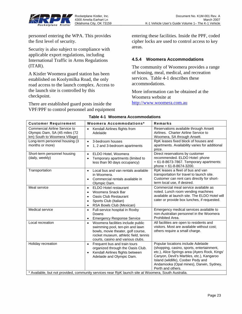
4.5.4 Woomera Accommodations
The community of Woomera provides a range of housing, meal, medical, and recreation services. Table 4-1 describes these accommodations.
More information can be obtained at the Woomera website at http://www.woomera.com.au
Table 4-1 Woomera Accommodations Customer Requirement Woomera Accommodat ions* Remarks Commercial Airline Service to Olympic Dam, SA (45 miles (72 km) South to Woomera Village)
• Kendall Airlines flights from Adelaide
Reservations available through Ansett Airlines. Charter Airline Service to Woomera, SA through Ansett.
Long-term personnel housing (3 months or more)
• 3-bedroom houses • 1, 2 and 3-bedroom apartments
RpK leases fixed block of houses and apartments. Availability varies for additional price.
Short-term personnel housing (daily, weekly)
• ELDO Hotel, Woomera • Temporary apartments (limited to
less than 90 days occupancy)
Direct reservations by customer recommended. ELDO Hotel: phone + 61-8-8673-7867. Temporary apartments: phone + 61-8-8674-3200.
Transportation • Local bus and van rentals available in Woomera.
• Commercial rentals available in Olympic Dam.
RpK leases a fleet of bus and van transportation for travel to launch site. Customer can rent cars directly for short-term local use, if desired.
Meal service • ELDO Hotel restaurant • Woomera Snack Bar • Oasis Club Restaurant • Sports Club (Italian) • RSA Bowls Club (Mexican)
Commercial meal service available as noted. Lunch room vending machines available at launch site. The ELDO Hotel will cater or provide box lunches, if requested.
Medical service • Full-service hospital in Roxby Downs
• Emergency Response Service
Emergency medical services available to non-Australian personnel in the Woomera Prohibited Area.
Local recreation • Woomera facilities include public swimming pool, ten-pin and lawn bowls, movie theater, golf course, rocket museum, athletic field, tennis courts, casino and various clubs.
All facilities are open to residents and visitors. Most are available without cost; others require a small charge.
Holiday recreation • Frequent bus and train tours organized through the Oasis Club.
• Kendall Airlines flights between Adelaide and Olympic Dam.
Popular locations include Adelaide (shopping, casino, sports, entertainment, etc.), Alice Springs area (Ayers Rock, Kings’ Canyon, Devil’s Marbles, etc.), Kangaroo Island (wildlife), Coober Pedy and Andamooka (Opal mines), Darwin, Sydney, Perth and others.
* Available, but not provided, community services near RpK launch site at Woomera, South Australia.
Rocketplane Kistler, Inc. Document No. K1M-001 Rev. A 4300 Amelia Earhart Ln March 2007Oklahoma City, OK 73159 K-1 Vehicle User’s Guide Volume 1– The K-1 Vehicle
Page 24
5. SAFETY5.1 Introduction
In Australia, Kistler Woomera Pty. Ltd. is responsible for the safety of vehicle operations and compliance with applicable regulations. The Director of Quality and Safety is the focal point for coordination of all program safety efforts and implementation of requirements.
Assuring safety during conduct of hazardous operations at Spaceport Woomera is the joint responsibility of RpK and the customer. Full integration of payload unique procedures and customer personnel into the RpK launch site operations is essential.
5.2 Personnel and Procedures
To ensure safety of personnel and equipment during payload preparation and subsequent launch operations, the customer is required to support development of payload unique procedures and training of on-site personnel. The customer will submit all hazardous payload processing procedures for review and approval by Kistler Woomera.
Customer personnel are to be skilled in processing operations on the payload and in operations performed at Kistler Woomera. Customer personnel will be provided safety training for operations and emergency procedures unique to the Woomera launch site facilities.
5.3 Payload and Support Equipment Design
The design of all customer payload and support equipment to be used at Spaceport Woomera shall be in accord with prudent industry practices that minimize safety risks.
Particular emphasis will be applied to mitigate launch site operational hazards related to pressurized systems. Customer data supporting
the design and safe operation of payload pressurization systems shall be submitted to Kistler Woomera for review. All pressure vessels and tanks at the launch site shall have a minimum 2-to-1 factor of safety. The factor of safety is defined as the ratio between the operating pressure and the design burst pressure.
5.4 Safety Approval Process
For the first launch of a payload, the safety approval process will follow a three-phase approach. Follow-on missions of the same payload will use an abbreviated version of this approach in which changes to the previously approved mission are identified.
Phase 1 – Hazard Identification. This phase includes the identification of all hazards associated with the payload design, processing, operations, and identification of means of controlling the hazards.
Phase 2 – Hazard Mitigation. In this phase the customer design, manufacturing, qualification and acceptance documentation will be reviewed to assure minimal safety risk during payload preparation and launch operations.
Phase 3 – Compliance Verification. During this phase, Kistler Woomera will assess customer documentation to verify compliance with K-1 safety requirements and applicable regulations.
During each phase, the data will be evaluated for completeness and actions taken to close open issues.
5.5 Safety Meetings and Reviews
Progress of the safety approval process will be routinely addressed at Launch Operations Working Group meetings. Verification that all safety requirements have been satisfied will be a part of the Launch Readiness Review. Any open

Rocketplane Kistler, Inc. Document No. K1M-001 Rev. A 4300 Amelia Earhart Ln March 2007Oklahoma City, OK 73159 K-1 Vehicle User’s Guide Volume 1– The K-1 Vehicle
Page 25
safety issues following this review will be recorded and final disposition completed and agreed to by mission management prior to proceeding with launch operations.