k vijayakumar_non invasive rail track detection - iopscience
TRANSCRIPT
Journal of Physics Conference Series
OPEN ACCESS
Non invasive rail track detection system usingmicrowave sensorTo cite this article K Vijayakumar et al 2009 J Phys Conf Ser 178 012033
View the article online for updates and enhancements
You may also likeMeasurement of transient force producedby a propagating arcmagnetohydrodynamic plasma actuator inquiescent atmospheric airYoung Joon Choi Jayant Sirohi andLaxminarayan L Raja
-
Effects of train driving modes and the railfoundation structure on the rail side wearin small-radius curvesD O Potapov Yu L Tuley S V Kulik et al
-
Theoretical basis of quality assessment ofrailway technical conditionA M Shtompel Ye M Korostelov V MBatsamut et al
-
Recent citationsBoosting the Tunable MicrowaveScattering Signature of Sensing ArrayPlatforms Consisting of AmorphousFerromagnetic Fe225Co7275Si10B15Microwires and Its Amplification byIntercalating Cu MicrowiresDiego Archilla et al
-
Dharmpal Singh et al-
Aaradhya Agarwal et al-
This content was downloaded from IP address 179109369 on 08122021 at 0356
Non invasive rail track detection system using Microwave sensor
K Vijayakumar SR Wylie J D Cullen CC Wright AI AI-Shammarsquoa
General Engineering Research Institute (GERI) Liverpool John Moores University Byrom Street L3 3AF United Kingdom
VKarunamoothei2006ljmuacuk
Abstract As fuel costs continue to rise efficient public transport especially rail will play an increasingly important role in the UK and worldwide For the safe operation of the rail system it is necessary that the condition of the rails can be monitored on a continual basis An important part of this monitoring process is crack detection Much research effort has been spent in the development of reliable repeatable crack detection methods for the use on the service rail In this research a new crack detection method has been investigated which utilizes microwave sensors to inspect the rail surface Initial data from experiment are presented
1 Introduction This research has investigated a new crack detection method for rail tracks which utilizes microwave sensor to inspect the rail surface during the passage of a train wheel The main idea is to design a new sensor that can obtain a level of accuracy well above the industrial demands of 95 to detect defects in rail tracks This research could be a vital progression for the railway industry The railway was one of the key factors in the industrial revolution and the development of the modern industrial societies of the world The need for good transportation for both freight and passengers is still just as important in modern society It is even argued that the railways alone had the largest impact of all innovations in initiating economic growth providing the people in industrial societies with higher living standards [1] Britain for instance has 16116 route kilometres which need to be inspected and maintained if derailments are to be avoided Since 1995 nineteen new sections of passenger line and 52 new stations have been added Britain now has the fastest growing railway network in Europe with passenger kilometres rising by 431 during 200607 and journeys by 438 compared to ten years earlier Freight tonne kilometres have increased by 496 during 200607 [2] About 400 accidents occur every year easily one of the worst in world of which 60 are caused by human error Derailments account for 70 of all accidents with level crossing accidents accounting for another 25 These statistics speak for themselves unless something is done immediately accidents and the consequent loss of life will be inevitable [3] In Britain derailments occur about twice a week and although the vast majorities are minor serious accidents such as the Hatfield rail crash which occurred on 17th October 2000 will happen The train was travelling at over 115mph four people were killed and a further seventy injured The investigation found was that a rail had fragmented when the train passed over it and that cause was gauge corner crackingrdquo which mean microscopic cracks in the rails Such cracks are caused by the high loads under the wheels where the wheels make contact with the rail surface [4] Another fatal accident occurred on 23rd February 2007 when a train travelling at
Sensors amp their Applications XV IOP PublishingJournal of Physics Conference Series 178 (2009) 012033 doi1010881742-65961781012033
ccopy 2009 IOP Publishing Ltd 1
about 145kph (90mph) from London to Glasgow derailed near the village of Grayrigg one passenger died and twenty-two were injured The accident came five years after defective points caused Britainrsquos last major rail disaster at Potters Bar in 2002[5] In this paper we introduce a Microwave horn antenna which is being used to detect the crack in rail track
2 Microwave Theory Basically it is describes about the electromagnetic waves with wavelength ranging from 1mm to 1mThe frequency between 03 GHz and 300GHz in free space [6] An electric field is created by electric charges and a magnetic field is created by moving electric charges A time changing magnetic field produces an electric field and vice versa These electric and magnetic fields are represented by Maxwellrsquos equations The solutions of Maxwellrsquos equations are electromagnetic waves in which electric and magnetic fields travel together though space at the speed of light [78] The features of electromagnetic waves are frequency wavelength impedance power density and phase Microwave systems transmit microwaves from their transmitter through space to a receiver [9] But inside the transmitter and the receiver microwaves cannot be conducted efficient by wires so they are transmitted from one component to another inside microwave transmission lines [10]
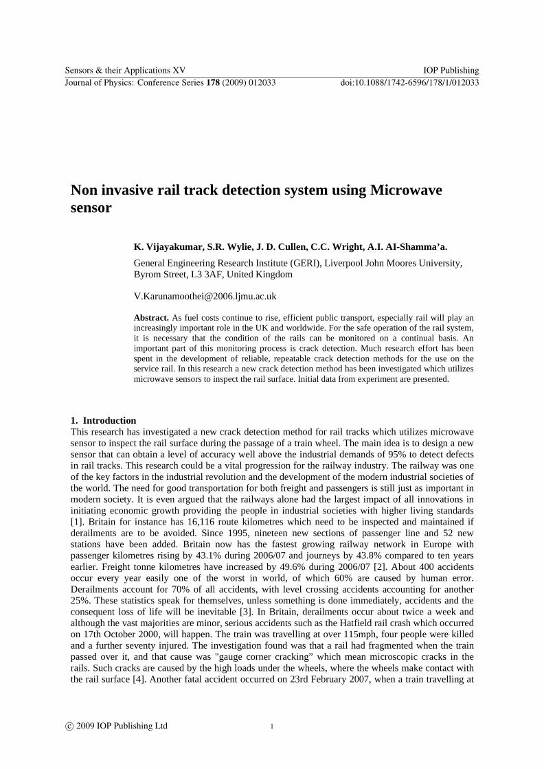
3 Microwave Horn Antenna Microwave horn antenna may be involved as a flared-out or opened out waveguide [11] The horn will produce a uniform phase front with larger aperture than the waveguide with greater directivity [12] Microwave horn antenna with dimensions 42mm length and 30mm width has been used for the experiment With a frequency range between 8GHz to 12GHz The simulation result using High Frequency Simulation Structure software (HFSS) is shown in Fig1
Figure 1 HFSS simulation of the microwave horn antenna above a crack
4 Model simulation result by using HFSS High Frequency Structure Simulator (HFSS) is an interactive software package which been used to understand how the Microwave Horn Antenna and the rail interact HFSS is the industry-standard software for S-parameter and this software has been developed to allow for 2D and 3D visualization of the radiation pattern for many different types of antennas including Microwaves Horn Sensor [1314] HFSS not only improves engineering productivity reduces development time and better assures first pass design success but also make it easy to design simulate and validate complex high performance RF microwave millimetres wave device and so on An HFSS project is a folder that includes one or more HFSS models or designs [15] Each design ultimately includes a geometric model its boundary condition and material assignments and field solution and post-processing information
Sensors amp their Applications XV IOP PublishingJournal of Physics Conference Series 178 (2009) 012033 doi1010881742-65961781012033
2
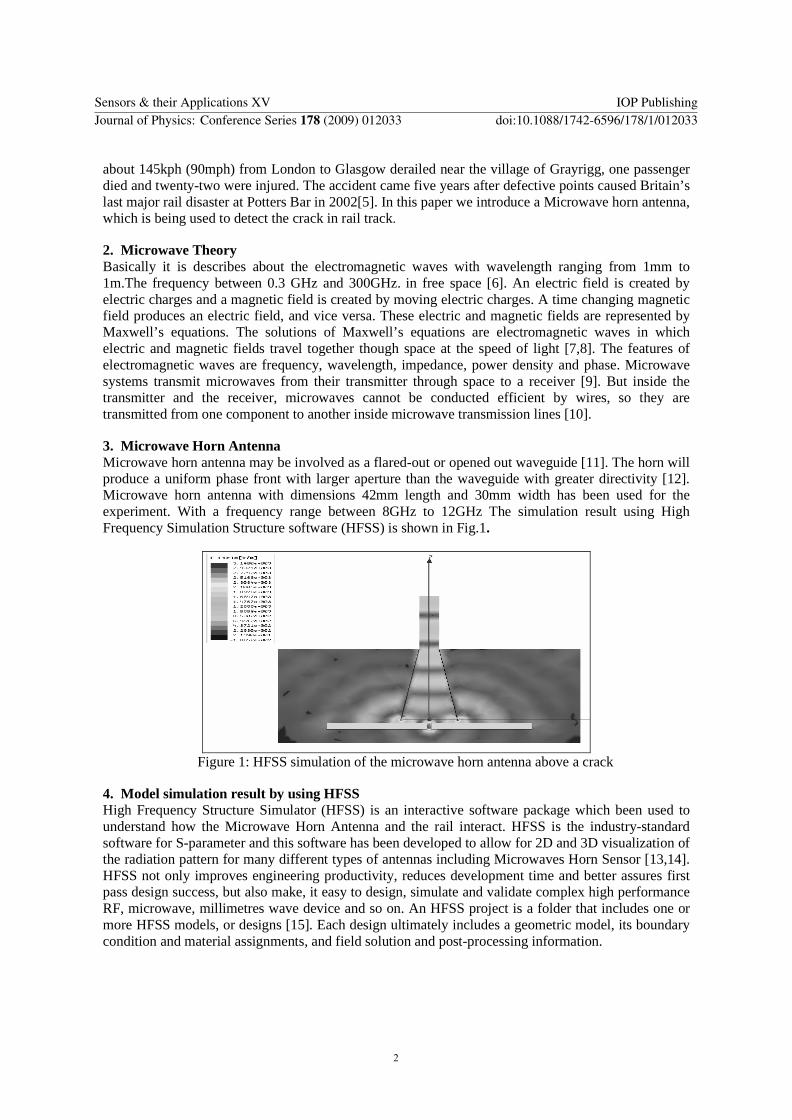
Figure 2 Simulation snapshot taken from the normal rail
Figure 2 shows the E-Field of the Microwave Sensor the E-Field of the Microwave Horn Sensor It is found when the crack is closed the minimum S11 shifts to a lower frequency
Figure 3 S11 Plot result for a normal surface
Figure 3 presents the XY pattern Graph of Microwave horn sensor It shows that the simulation result occurs in the xz plane when they is a no defect occur in rail track
Figure 4 Simulation snapshot taken from the defect rail
Figure 4 shows the E-Field of the Microwave Sensor it is found that the electric field is in the outward direction from the defect rail
Sensors amp their Applications XV IOP PublishingJournal of Physics Conference Series 178 (2009) 012033 doi1010881742-65961781012033
3
Figure 5 S11 Plot result for the crack surface
Figure 5 presents the S11 for a range of frequencies at the crack The cut-off frequencies are a
23mmtimes10mm TE01 or TE10 is 65GHz
5 Experiment set up using Microwave sensor The experiment setup is shown in Fig6 a microwave test set used to drive the horn and measure the amount of power reflected from the track over a range of frequency as the horn is moving along the track shows the variation in signal at 95GHZ as the horn passes over the crack which as shown in Fig 7 and Fig 8 The data presented here constitutes the first step in the development of a train based analysis system for defect detection in rails All the results are analysed using a spectrum analyzer This is used to primarily measures power and frequency The spectrum analyzer is used to locate and measure the powerenergy of the electromagnetic wave reflecting off the rail track frequencies between 8 GHz and 12 GHz A sample of rail track which is 400mm long has been used for testing purposes In this experiment an additional crack has been added The reason is to identify in more detail how accurately the Microwave sensor can detect the crack in order to get good output Fig6 also shown the output from the spectrum analyser at the same cracks the reading was constant as shown in Fig6 until the crack is reached They have a width between 02 to 03 cm The electrical field will usually effect back from the normal surface but it will be radiated to free space when the gap occurs in the rail track and only very limited amounting electrical field will reflect back That can be seen clearly in the graph as well on the spectrum analyser
Figure 6 Experiment set up testing using Microwave horn antenna
Sensors amp their Applications XV IOP PublishingJournal of Physics Conference Series 178 (2009) 012033 doi1010881742-65961781012033
4
Figure 7 The output result obtain for second phase experiment
Figure 8 Experimental results obtained using microwave horn antenna
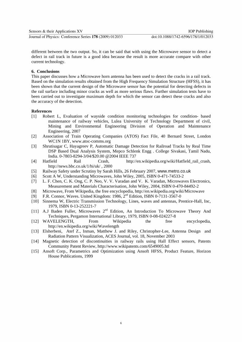
Figure 9 The minimum S11 value shift to a higher frequency when there is a defect
Figure 9 show the simulation result obtain with two different reading that is reading obtain with rail track without defect and rail track with defect occur Based on the result it can be seen clearly the
Sensors amp their Applications XV IOP PublishingJournal of Physics Conference Series 178 (2009) 012033 doi1010881742-65961781012033
5
different between the two output So it can be said that with using the Microwave sensor to detect a defect in rail track in future is a good idea because the result is more accurate compare with other current technology
6 Conclusions This paper discusses how a Microwave horn antenna has been used to detect the cracks in a rail track Based on the simulation results obtained from the High Frequency Simulation Structure (HFSS) it has been shown that the current design of the Microwave sensor has the potential for detecting defects in the rail surface including minor cracks as well as more serious flaws Further simulation tests have to been carried out to investigate maximum depth for which the sensor can detect these cracks and also the accuracy of the detection
References [1] Robert L Evaluation of wayside condition monitoring technologies for condition- based
maintenance of railway vehicles Lulea University of Technology Department of civil Mining and Environmental Engineering Division of Operation and Maintenance Engineering 2007
[2] Association of Train Operating Companies (ATOS) Fact File 40 Bernard Street London WC1N 1BY wwwatoc-commsorg
[3] Shrutisagar C Hayagreev P Automatic Damage Detection for Railroad Tracks by Real Time DSP Based Dual Analysis System Mepco Schlenk Engg College Sivakasi Tamil Nadu India 0-7803-8294-304$2000 2004 IEEE 737
[4] Hatfield Rail Crash httpenwikipediaorgwikiHatfield_rail_crash httpnewsbbccouk1hiuk 2000
[5] Railway Safety under Scrutiny by Sarah Hills 26 February 2007 wwwmetrocouk [6] Scott A W Understanding Microwaves John Wiley 2005 ISBN 0-471-74533-2 [7] L F Chen C K Ong C P Neo V V Varadan and V K Varadan Microwaves Electronics
Measurement and Materials Characterisation John Wiley 2004 ISBN 0-470-84492-2 [8] Microwave From Wikipedia the free encyclopedia httpenwikipediaorgwikiMicrowave [9] FR Connor Waves United Kingdom 1986 2nd Edition ISBN 0-7131-3567-0 [10] Sinnema W Electric Transmission Technology Lines waves and antennas Prentice-Hall Inc
1979 ISBN 0-13-252221-7 [11] AJ Baden Fuller Microwaves 2nd Edition An Introduction To Microwave Theory And
Techniques Pergamon International Library 1979 ISBN 0-08-024227-8 [12] WAVELENGTH From Wikipedia the free encyclopedia
httpenwikipediaorgwikiWavelength [13] Elsherbeni Atef Z Inman Matthew J and Riley Christopher-Lee Antenna Design and
Radiation Pattern Visualization ACES Journal vol 18 November 2003 [14] Magnetic detection of discontinuities in railway rails using Hall Effect sensors Patents
Community Patent Review httpwwwwikipatentscom6549005htl [15] Ansoft Corp Parametrics and Optimization using Ansoft HFSS Product Feature Horizon
House Publications 1999
Sensors amp their Applications XV IOP PublishingJournal of Physics Conference Series 178 (2009) 012033 doi1010881742-65961781012033
6
Non invasive rail track detection system using Microwave sensor
K Vijayakumar SR Wylie J D Cullen CC Wright AI AI-Shammarsquoa
General Engineering Research Institute (GERI) Liverpool John Moores University Byrom Street L3 3AF United Kingdom
VKarunamoothei2006ljmuacuk
Abstract As fuel costs continue to rise efficient public transport especially rail will play an increasingly important role in the UK and worldwide For the safe operation of the rail system it is necessary that the condition of the rails can be monitored on a continual basis An important part of this monitoring process is crack detection Much research effort has been spent in the development of reliable repeatable crack detection methods for the use on the service rail In this research a new crack detection method has been investigated which utilizes microwave sensors to inspect the rail surface Initial data from experiment are presented
1 Introduction This research has investigated a new crack detection method for rail tracks which utilizes microwave sensor to inspect the rail surface during the passage of a train wheel The main idea is to design a new sensor that can obtain a level of accuracy well above the industrial demands of 95 to detect defects in rail tracks This research could be a vital progression for the railway industry The railway was one of the key factors in the industrial revolution and the development of the modern industrial societies of the world The need for good transportation for both freight and passengers is still just as important in modern society It is even argued that the railways alone had the largest impact of all innovations in initiating economic growth providing the people in industrial societies with higher living standards [1] Britain for instance has 16116 route kilometres which need to be inspected and maintained if derailments are to be avoided Since 1995 nineteen new sections of passenger line and 52 new stations have been added Britain now has the fastest growing railway network in Europe with passenger kilometres rising by 431 during 200607 and journeys by 438 compared to ten years earlier Freight tonne kilometres have increased by 496 during 200607 [2] About 400 accidents occur every year easily one of the worst in world of which 60 are caused by human error Derailments account for 70 of all accidents with level crossing accidents accounting for another 25 These statistics speak for themselves unless something is done immediately accidents and the consequent loss of life will be inevitable [3] In Britain derailments occur about twice a week and although the vast majorities are minor serious accidents such as the Hatfield rail crash which occurred on 17th October 2000 will happen The train was travelling at over 115mph four people were killed and a further seventy injured The investigation found was that a rail had fragmented when the train passed over it and that cause was gauge corner crackingrdquo which mean microscopic cracks in the rails Such cracks are caused by the high loads under the wheels where the wheels make contact with the rail surface [4] Another fatal accident occurred on 23rd February 2007 when a train travelling at
Sensors amp their Applications XV IOP PublishingJournal of Physics Conference Series 178 (2009) 012033 doi1010881742-65961781012033
ccopy 2009 IOP Publishing Ltd 1
about 145kph (90mph) from London to Glasgow derailed near the village of Grayrigg one passenger died and twenty-two were injured The accident came five years after defective points caused Britainrsquos last major rail disaster at Potters Bar in 2002[5] In this paper we introduce a Microwave horn antenna which is being used to detect the crack in rail track
2 Microwave Theory Basically it is describes about the electromagnetic waves with wavelength ranging from 1mm to 1mThe frequency between 03 GHz and 300GHz in free space [6] An electric field is created by electric charges and a magnetic field is created by moving electric charges A time changing magnetic field produces an electric field and vice versa These electric and magnetic fields are represented by Maxwellrsquos equations The solutions of Maxwellrsquos equations are electromagnetic waves in which electric and magnetic fields travel together though space at the speed of light [78] The features of electromagnetic waves are frequency wavelength impedance power density and phase Microwave systems transmit microwaves from their transmitter through space to a receiver [9] But inside the transmitter and the receiver microwaves cannot be conducted efficient by wires so they are transmitted from one component to another inside microwave transmission lines [10]
3 Microwave Horn Antenna Microwave horn antenna may be involved as a flared-out or opened out waveguide [11] The horn will produce a uniform phase front with larger aperture than the waveguide with greater directivity [12] Microwave horn antenna with dimensions 42mm length and 30mm width has been used for the experiment With a frequency range between 8GHz to 12GHz The simulation result using High Frequency Simulation Structure software (HFSS) is shown in Fig1
Figure 1 HFSS simulation of the microwave horn antenna above a crack
4 Model simulation result by using HFSS High Frequency Structure Simulator (HFSS) is an interactive software package which been used to understand how the Microwave Horn Antenna and the rail interact HFSS is the industry-standard software for S-parameter and this software has been developed to allow for 2D and 3D visualization of the radiation pattern for many different types of antennas including Microwaves Horn Sensor [1314] HFSS not only improves engineering productivity reduces development time and better assures first pass design success but also make it easy to design simulate and validate complex high performance RF microwave millimetres wave device and so on An HFSS project is a folder that includes one or more HFSS models or designs [15] Each design ultimately includes a geometric model its boundary condition and material assignments and field solution and post-processing information
Sensors amp their Applications XV IOP PublishingJournal of Physics Conference Series 178 (2009) 012033 doi1010881742-65961781012033
2
Figure 2 Simulation snapshot taken from the normal rail
Figure 2 shows the E-Field of the Microwave Sensor the E-Field of the Microwave Horn Sensor It is found when the crack is closed the minimum S11 shifts to a lower frequency
Figure 3 S11 Plot result for a normal surface
Figure 3 presents the XY pattern Graph of Microwave horn sensor It shows that the simulation result occurs in the xz plane when they is a no defect occur in rail track
Figure 4 Simulation snapshot taken from the defect rail
Figure 4 shows the E-Field of the Microwave Sensor it is found that the electric field is in the outward direction from the defect rail
Sensors amp their Applications XV IOP PublishingJournal of Physics Conference Series 178 (2009) 012033 doi1010881742-65961781012033
3
Figure 5 S11 Plot result for the crack surface
Figure 5 presents the S11 for a range of frequencies at the crack The cut-off frequencies are a
23mmtimes10mm TE01 or TE10 is 65GHz
5 Experiment set up using Microwave sensor The experiment setup is shown in Fig6 a microwave test set used to drive the horn and measure the amount of power reflected from the track over a range of frequency as the horn is moving along the track shows the variation in signal at 95GHZ as the horn passes over the crack which as shown in Fig 7 and Fig 8 The data presented here constitutes the first step in the development of a train based analysis system for defect detection in rails All the results are analysed using a spectrum analyzer This is used to primarily measures power and frequency The spectrum analyzer is used to locate and measure the powerenergy of the electromagnetic wave reflecting off the rail track frequencies between 8 GHz and 12 GHz A sample of rail track which is 400mm long has been used for testing purposes In this experiment an additional crack has been added The reason is to identify in more detail how accurately the Microwave sensor can detect the crack in order to get good output Fig6 also shown the output from the spectrum analyser at the same cracks the reading was constant as shown in Fig6 until the crack is reached They have a width between 02 to 03 cm The electrical field will usually effect back from the normal surface but it will be radiated to free space when the gap occurs in the rail track and only very limited amounting electrical field will reflect back That can be seen clearly in the graph as well on the spectrum analyser
Figure 6 Experiment set up testing using Microwave horn antenna
Sensors amp their Applications XV IOP PublishingJournal of Physics Conference Series 178 (2009) 012033 doi1010881742-65961781012033
4
Figure 7 The output result obtain for second phase experiment
Figure 8 Experimental results obtained using microwave horn antenna
Figure 9 The minimum S11 value shift to a higher frequency when there is a defect
Figure 9 show the simulation result obtain with two different reading that is reading obtain with rail track without defect and rail track with defect occur Based on the result it can be seen clearly the
Sensors amp their Applications XV IOP PublishingJournal of Physics Conference Series 178 (2009) 012033 doi1010881742-65961781012033
5
different between the two output So it can be said that with using the Microwave sensor to detect a defect in rail track in future is a good idea because the result is more accurate compare with other current technology
6 Conclusions This paper discusses how a Microwave horn antenna has been used to detect the cracks in a rail track Based on the simulation results obtained from the High Frequency Simulation Structure (HFSS) it has been shown that the current design of the Microwave sensor has the potential for detecting defects in the rail surface including minor cracks as well as more serious flaws Further simulation tests have to been carried out to investigate maximum depth for which the sensor can detect these cracks and also the accuracy of the detection
References [1] Robert L Evaluation of wayside condition monitoring technologies for condition- based
maintenance of railway vehicles Lulea University of Technology Department of civil Mining and Environmental Engineering Division of Operation and Maintenance Engineering 2007
[2] Association of Train Operating Companies (ATOS) Fact File 40 Bernard Street London WC1N 1BY wwwatoc-commsorg
[3] Shrutisagar C Hayagreev P Automatic Damage Detection for Railroad Tracks by Real Time DSP Based Dual Analysis System Mepco Schlenk Engg College Sivakasi Tamil Nadu India 0-7803-8294-304$2000 2004 IEEE 737
[4] Hatfield Rail Crash httpenwikipediaorgwikiHatfield_rail_crash httpnewsbbccouk1hiuk 2000
[5] Railway Safety under Scrutiny by Sarah Hills 26 February 2007 wwwmetrocouk [6] Scott A W Understanding Microwaves John Wiley 2005 ISBN 0-471-74533-2 [7] L F Chen C K Ong C P Neo V V Varadan and V K Varadan Microwaves Electronics
Measurement and Materials Characterisation John Wiley 2004 ISBN 0-470-84492-2 [8] Microwave From Wikipedia the free encyclopedia httpenwikipediaorgwikiMicrowave [9] FR Connor Waves United Kingdom 1986 2nd Edition ISBN 0-7131-3567-0 [10] Sinnema W Electric Transmission Technology Lines waves and antennas Prentice-Hall Inc
1979 ISBN 0-13-252221-7 [11] AJ Baden Fuller Microwaves 2nd Edition An Introduction To Microwave Theory And
Techniques Pergamon International Library 1979 ISBN 0-08-024227-8 [12] WAVELENGTH From Wikipedia the free encyclopedia
httpenwikipediaorgwikiWavelength [13] Elsherbeni Atef Z Inman Matthew J and Riley Christopher-Lee Antenna Design and
Radiation Pattern Visualization ACES Journal vol 18 November 2003 [14] Magnetic detection of discontinuities in railway rails using Hall Effect sensors Patents
Community Patent Review httpwwwwikipatentscom6549005htl [15] Ansoft Corp Parametrics and Optimization using Ansoft HFSS Product Feature Horizon
House Publications 1999
Sensors amp their Applications XV IOP PublishingJournal of Physics Conference Series 178 (2009) 012033 doi1010881742-65961781012033
6
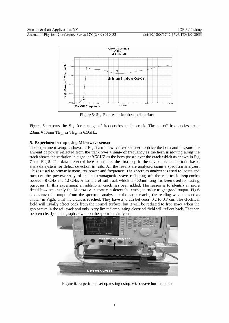
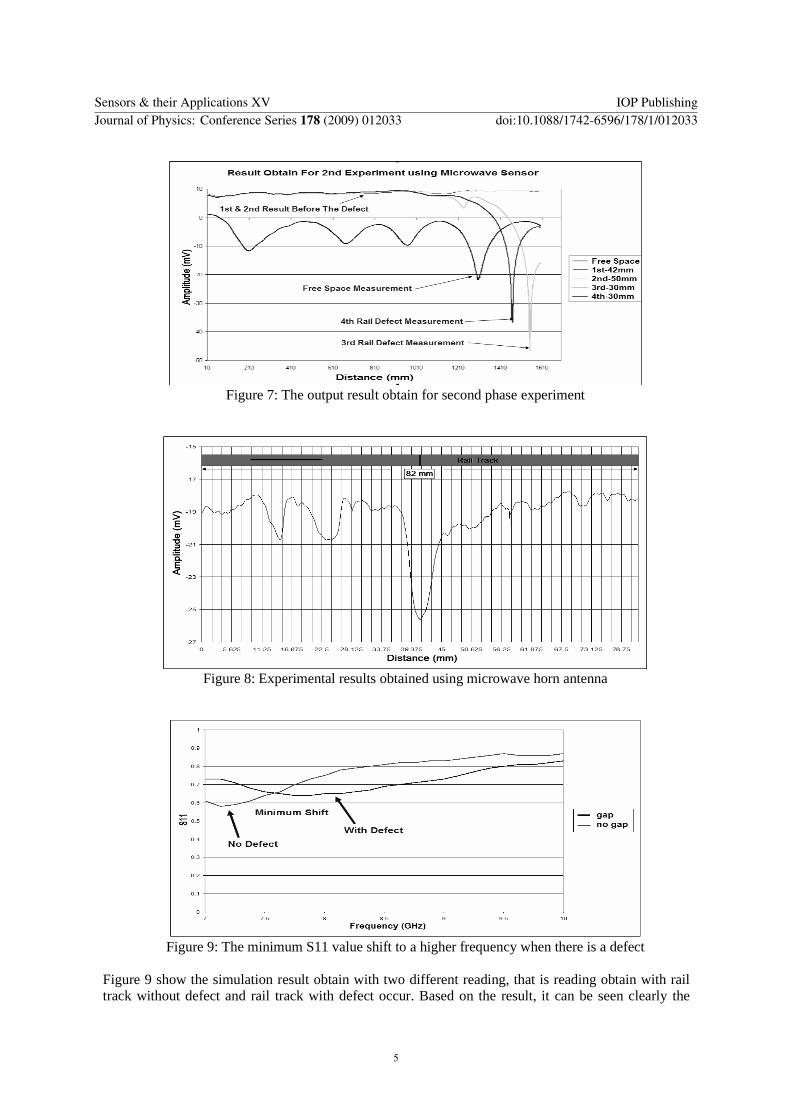