k1el cpo · j4 - 1/8” audio jack c1 - 100 uf electrolytic capacitor c2, 5, - .1 uf ceramic...
TRANSCRIPT
K1EL Morse Code Practice Oscillator CPO
Features Description Keyer speed range: Limited only by keying source True Sine wave tone output CPO Tone Volume Control CPO Tone Frequency Control Internal Speaker 1/8” External Speaker/Headphone Jack RCA Key Input Jack RCA Key Sync Input Jack External Power 8-12 VDC Custom Metal Enclosure
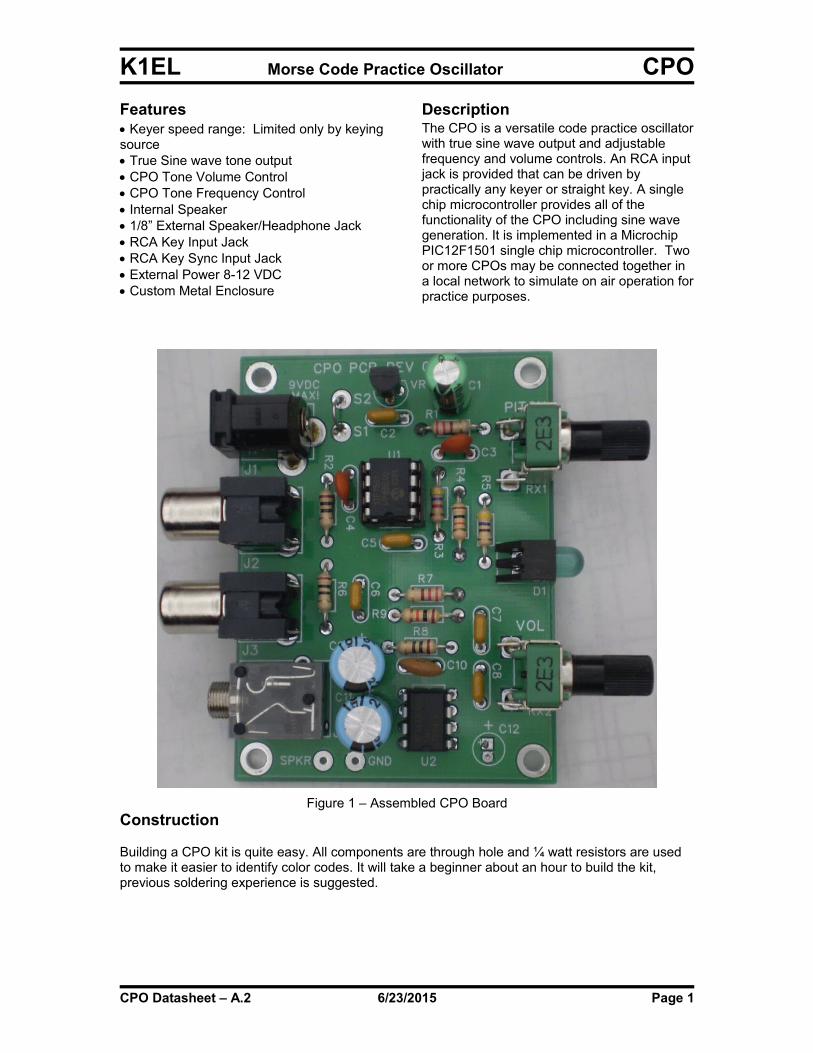
The CPO is a versatile code practice oscillatorwith true sine wave output and adjustable frequency and volume controls. An RCA input jack is provided that can be driven by practically any keyer or straight key. A single chip microcontroller provides all of the functionality of the CPO including sine wave generation. It is implemented in a Microchip PIC12F1501 single chip microcontroller. Two or more CPOs may be connected together in a local network to simulate on air operation forpractice purposes.
Figure 1 – Assembled CPO BoardConstruction
Building a CPO kit is quite easy. All components are through hole and ¼ watt resistors are used to make it easier to identify color codes. It will take a beginner about an hour to build the kit, previous soldering experience is suggested.
CPO Datasheet – A.2 6/23/2015 Page 1
K1EL Morse Code Practice Oscillator CPO
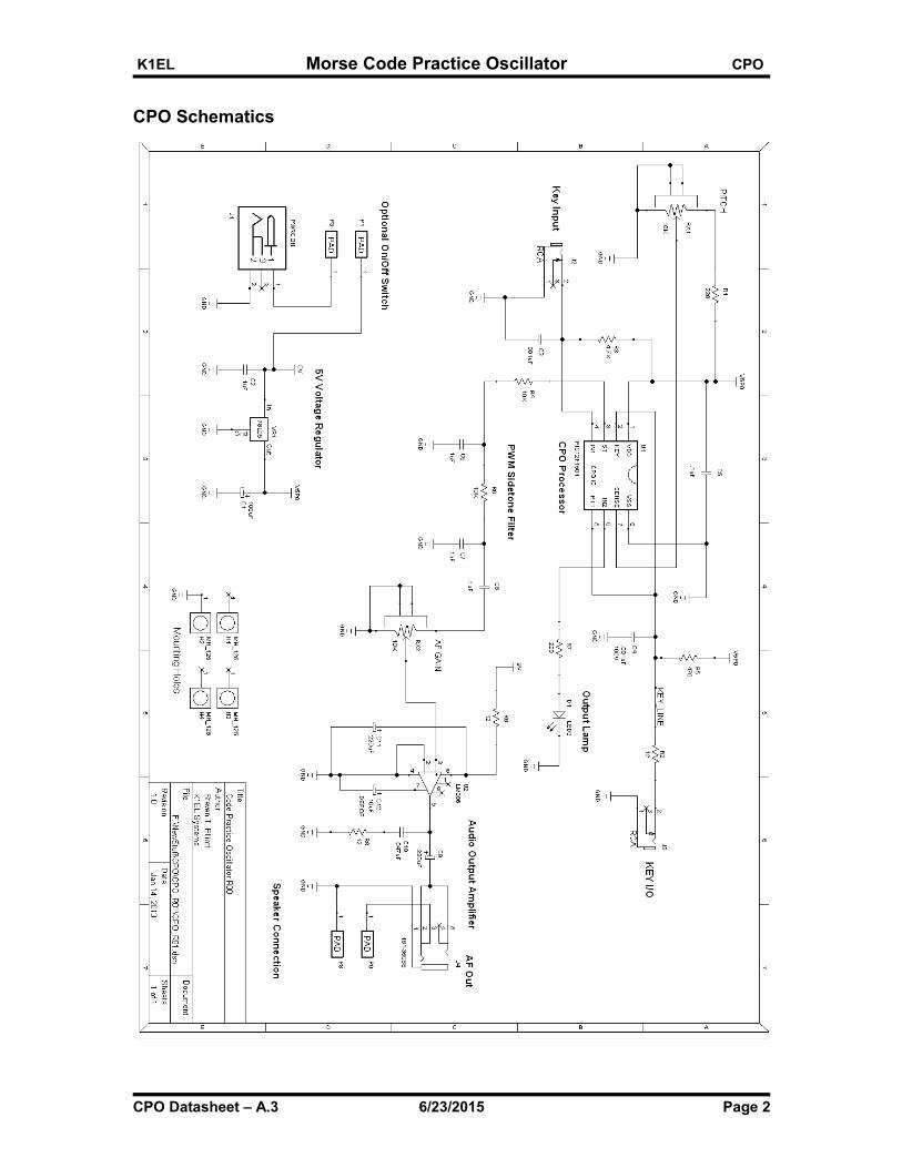
CPO Schematics
CPO Datasheet – A.3 6/23/2015 Page 2
K1EL Morse Code Practice Oscillator CPO
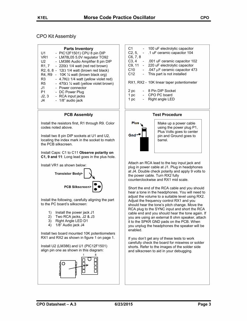
CPO Kit Assembly
CPO Datasheet – A.3 6/23/2015 Page 3
PCB Assembly
Install the resistors first, R1 through R9. Color codes noted above.
Install two 8 pin DIP sockets at U1 and U2, locating the index mark in the socket to match the PCB silkscreen.
Install Caps: C1 to C11 Observe polarity on C1, 9 and 11: Long lead goes in the plus hole. Install VR1 as shown below:
Transistor Body>
PCB Silkscreen>
Install the following, carefully aligning the part to the PC board’s silkscreen:
1) Install the power jack J12) Two RCA jacks, J2 & J33) Right Angle LED D14) 1/8” Audio jack J4
Install two board mounted 10K potentiometers RX1 and RX2 as shown in figure 1 on page 1.
Install U2 (LM386) and U1 (PIC12F1501)align pin one as shown in this diagram:
1 8
Test Procedure
Attach an RCA lead to the key input jack and plug in power cable at J1. Plug in headphones at J4. Double check polarity and apply 9 volts to the power cable. Turn RX2 fully counterclockwise and RX1 mid scale.
Short the end of the RCA cable and you should hear a tone in the headphones. You will need to adjust the volume to a suitable level using RX2. Adjust the frequency control RX1 and you should hear the tone’s pitch change. Move the RCA plug to the SYNC input and short the RCA cable end and you should hear the tone again. Ifyou are using an external 8 ohm speaker, attachit to the SPKR GND pads on the PCB. When you unplug the headphones the speaker will be enabled.
If you don’t get any of these tests to work carefully check the board for miswires or solder shorts. Refer to the images of the solder side and silkscreen to aid in your debugging.
Parts InventoryU1 - PIC12F1501) CPU 8 pin DIPVR1 - LM78L05 5.0V regulator TO92U2 - LM386 Audio Amplifier 8 pin DIPR1, 7 - 220 1/4 watt (red red brown)R2, 6, 8 - 12 1/4 watt (brown red black)R4, R9 - 10K ¼ watt (brown black org)R3 - 4.7K 1/4 watt (yellow violet red)R5 - 470 ¼ watt (yellow violet brown)J1 - Power connectorP1 - DC Power PlugJ2, 3 - RCA input jacksJ4 - 1/8” audio jack
C1 - 100 uF electrolytic capacitorC2, 5, - .1 uF ceramic capacitor 104C6, 7, 8C3, 4 - .001 uF ceramic capacitor 102C9, 11 - 220 uF electrolytic capacitorC10 - .047 F ceramic capacitor 473C12 - This part is not installed
RX1, RX2 - 10K linear taper potentiometer 2 pc - 8 Pin DIP Socket1 pc - CPO PC board1 pc - Right angle LED
Make up a power cable using the power plug P1,Plus Volts goes to centerpin and Ground goes to barrel.

K1EL Morse Code Practice Oscillator CPO
CPO PCB Images
Figure 2 – Assembled CPO Board Close Up, Top Half
Figure 3 – Assembled CPO Board Close Up, Bottom Half
CPO Datasheet – A.3 6/23/2015 Page 4

K1EL Morse Code Practice Oscillator CPO
Figure 4 – Printed Circuit Board Image
CPO Datasheet – A.3 6/23/2015 Page 5

K1EL Morse Code Practice Oscillator CPO
Key Sync Mode Description
A handy feature that is indispensable in Morse Code classes is the key sync mode. This can be wiredto one or more CPOs and provides a virtual Morse network. If two CPOs are connected together, keying one will cause the Morse tone to be heard in the both the local and remote CPO. Either side can key at any time and be heard remotely in all connected CPOs. If both sides key at the same time,this will be detected as invalid Morse and encourages the operators to use standard exchange practice. The cabling is simple two wire cables with an RCA plug at both ends. If more than two CPOsare networked together, RCA Y cables are required to bridge the central CPOs.
Key Sync Operation
This is diagram illustrates a set of three CPOs connected in a network. The interconnecting cables are just simple two wire RCA cable, the middle station would have a Y cable that allow it tobe connected to two other CPOs. The CPOs could be located in different rooms or up to 100 feet away. When any station keys their CPO, a tone will be heard both locally and at the other two CPOs. Volume and frequency settings only affect the local station allowing each station to set their CPO to their liking, If two stations key at the same time they will collide resulting in unreadable Morse. This is similar to what happens when two stations send at the same time live on air. This greatly helps beginners understand and practice proper operating techniques
CPOPower Connector
9 VDC
Key input from keyer or
straight key
Key In
Sync
Audio
Speaker
CPOPower Connector
9 VDC
Key In
Sync
Audio
Speaker
CPOPower Connector
9 VDC
Key In
Sync
Audio
Speaker
Station #1
Station #2
Station #3
Key input from keyer or
straight key
Key input from keyer or
straight key
Figure 5 -Triple CPO Hook Up Diagram
CPO Datasheet – A.3 6/23/2015 Page 6
K1EL Morse Code Practice Oscillator CPO
Contact Information
The CPO keyer is fully guaranteed; if you are not satisfied please return the CPO for a full refund.Questions will be handled by snail-mail or e-mail via these addresses:
Steven T. Elliott K1EL or e-mail: [email protected] Meadowcrest DriveBedford, NH 03110 USA
Watch the Hamcrafters Website for latest updates and new product offerings: http://www.hamcrafters.com
Revision History
CPO Chip Rev A Original Release
Manual Rev A.3 - Changed BOM to match schematics R4 & R9 = 10K
Index
Features............................................................................................................................................................1
Description........................................................................................................................................................1
Figure 1 – Assembled CPO Board...........................................................................................................1Construction......................................................................................................................................................1
Key Sync Mode Description..............................................................................................................................6
CPO Schematics...............................................................................................................................................2
CPO Kit Assembly.............................................................................................................................................3
CPO PCB Images.............................................................................................................................................4
Figure 2 – Assembled CPO Board Close Up, Top Half...........................................................................4Figure 3 – Assembled CPO Board Close Up, Bottom Half.....................................................................4Figure 4 – Printed Circuit Board Image...................................................................................................5
Key Sync Operation..........................................................................................................................................6
Figure 5 -Triple CPO Hook Up Diagram.................................................................................................6Contact Information...........................................................................................................................................7
Revision History................................................................................................................................................7
Index................................................................................................................................................................. 7
Appendix A - Kit Construction Hints..................................................................................................................8
Appendix B - A Note About Safety....................................................................................................................9
Appendix C - Soldering Basics.........................................................................................................................9
CPO Datasheet – A.3 6/23/2015 Page 7
K1EL Morse Code Practice Oscillator CPO
Appendix A - Kit Construction Hints
1. Find a good workspace.
It is essential that you have a good place to work on your kit,
You will need room to spread out your parts and have access to tools. Good lighting and ventilation is essential. A magnifying glass or visor is highly recommended.
2. Have the proper tools.
At a bare minimum you will need:
Small side cutters, flush cutters are a plus.
Small needle nosed pliers
Small flat blade & Philips head screw drivers
A good quality, 40-60Watt, temperature controlled Soldering Iron. The price has come down on these lately, you can buy a Weller WLC100 40W soldering station with adjustable temperature control for $40 on Amazon.
3. Read the Instructions First.
Read through the assembly instructions completely and have everything on hand before you start. Inventory the kit parts, make sure you have ALL of them.
4. Follow the assembly instructions in order.
Although not always obvious, the order in which parts are added to a board is important and should followed. Sometimes sections are installed and tested in order or there could be a mechanical clearance consideration.
5. Keep your Workplace Clean and Orderly.
Nothing spoils a kit building experience more than lost parts. Second to that is stray bits of dirt and metal that get into a printed circuit board assembly. Our PC boards are nicely plated and accept solder easily. There is no need to clean the board with steel wool before starting. A good rosin core solder will work fine. Lead free solder is recommended for health reasons.
6. Take your time.
There is no need to rush, enjoy the process and the end result will be much better. Moving too quickly or working when you are tired often leads to big mistakes which could be difficult if not impossible to fix.
CPO Datasheet – A.3 6/23/2015 Page 8
K1EL Morse Code Practice Oscillator CPO
Appendix B - A Note About Safety
Burns to your skin can be very painful and can lead to serious injury.
Burns to your eyes can be catastrophic.
Toxic fumes can cause serious harm.
Flying objects such as wire ends etc. can cause painful and serious injuries.
When building your kit please remember that Soldering Irons and Solder are used at High Temperatures !
Soldering Irons can remain hot for many minutes after being turned off. Never touch the tip to seeif it is hot. Touch the tip to a wet pad to test for temperature.
Wear safety glasses to protect your eyes from flying objects.
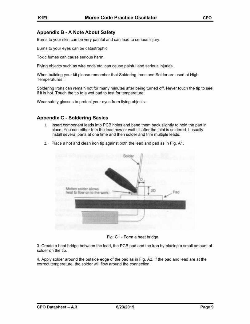
Appendix C - Soldering Basics
1. Insert component leads into PCB holes and bend them back slightly to hold the part in place. You can either trim the lead now or wait till after the joint is soldered. I usually install several parts at one time and then solder and trim multiple leads.
2. Place a hot and clean iron tip against both the lead and pad as in Fig. A1.
Fig. C1 - Form a heat bridge
3. Create a heat bridge between the lead, the PCB pad and the iron by placing a small amount of solder on the tip.
4. Apply solder around the outside edge of the pad as in Fig. A2. If the pad and lead are at the correct temperature, the solder will flow around the connection.
CPO Datasheet – A.3 6/23/2015 Page 9

K1EL Morse Code Practice Oscillator CPO
Fig. C2 - Spread solder around the work
5. Remove the solder and then remove the iron.
Fig C3 - Remove the solder
6. Allow the joint to cool and visually inspect for defects or other problems. You should have a solder joint with a bright shiny finish and a profile like that shown in the middle picture below.
Fig. C4 - Solder quantity comparison
CPO Datasheet – A.3 6/23/2015 Page 10