kan zheng, lin huang, gang li, hanwen cao, …k25zheng/pdf/sdr implementation of b3g... · kan...
TRANSCRIPT

30 ||| 1556-6072/08/$25.00©2008IEEE IEEE VEHICULAR TECHNOLOGY MAGAZINE | JUNE 2008
Digital Object Identifier 10.1109/MVT.2008.923968
Kan Zheng,Lin Huang,
Gang Li, Hanwen Cao, Wenbo Wang, and
Mischa Dohler

Now that the third generation (3G) mobile systemhas been developed and, with varying success,deployed worldwide, the design process ofbeyond 3G (B3G) systems has gained in impetus.
Key initiatives in this direction are carried out by the 3Gpartnership project’s (3GPP’s) long-term evolution (LTE)project, which proposes innovative approaches toincrease the spectral efficiency and hence decrease thecost per b/s/Hz over the air interface.
With increasingly congested frequency bands and anever-growing demand for higher data rates, the technicalrequirements on the emerging B3G air-interface are aug-menting. For instance, anticipated download rates are of upto 100 Mb/s and upload rates of 50 Mb/s for every 20 MHz ofspectrum, where at least 200 users should be supported forevery 5 MHz [1]. As for the downlink, LTE is currently inves-tigating the use of orthogonal frequency division multi-plexing (OFDM) with adaptive modulation, a carrierspacing of 15 kHz and a maximum of 2048 subcarri-ers; furthermore, single-user and multiuser MIMOis supported. As for the uplink, single-carrier(SC) frequency division multiple access(FDMA) is under consideration because ityields a low peak to average powerratio and hence facilitates the useof cheaper power amplifiers.
Numerous mathemati-cal and simulation stud-ies have already beenperformed to corroborate the advantages of abovedescribed (as well as other proposed) B3G air-interfaces[2], [3]. Real-world prototyping implementations of thesealgorithms, however, are rare because of high financialcosts and long development times. Nonetheless, suchimplementations are vital because they allow exposure ofimportant design flaws, unexpected system behaviors,real-world impairments, and performance-susceptibleparameters.
Various prototyping testbeds have already beenreported in the literature; pertinent examples are [4] and[5] and references therein. Typically, they report hard-ware solutions, including MIMO channel measurements,implementation of real-time MIMO algorithms, and proto-typing of new wireless standards. These testbeds, howev-er, are generally designed by using dedicated hardwaresuch as field programmable gate arrays (FPGA), applica-tion specific integrated circuits (ASICs), and digital signalprocessors (DSPs). While usually being run-time opti-mized, the disadvantage of dedicated hardware is its lackof flexibility, i.e., development is long and exportationonto other platforms cumbersome.
More flexible and modular approaches are hencedesired by today’s cutting-edge industry. Besides produc-ing stable and reproducible results, a flexible testbedallows the modification of system parameters and adapt-
ing functionality of different layers to experimental needs.An enabler of such a prototyping platform is the softwaredefined radio (SDR), which in essence is a minimum set ofprogrammable hardware facilitating the processing of dig-itized signals in software [6].
SDR provides sufficient flexibility by performing thefunctions of the physical layer (PHY) and medium accesscontrol (MAC) layer in software, while only the radio fre-
quency (RF) and signal conversion functions areimplemented in programmable hardware.
Instead of DSPs or FPGAs, a general-purpose microprocessor can be
used for SDR implementation,which was initially introduced
by Bose (www.vanu.com).Wire less -3G - for -Free
(www.wireless3g4free.com)and [7] have shown that thecluster of general purposepersonal computers (PCs) isa compelling platform forimplementing the wirelesssystems. In such a platform,
commonplace languages suchas C/C++ as well as familiar
development tools can be used;the SDR design is hence open to
an emerging community of soft-ware radio developers. Furthermore,
parallel processing is being seen as the only cost-effectiveand scalable method for realizing fast solutions of computa-tionally large and data-intensive problems. The emer-gence of inexpensive parallel computers, such ascommodity desktop multiprocessors and clusters ofworkstations, has made such parallel methods generallyapplicable. The GNU’s Not Unix (GNU) radio (www.gnura-dio.org) follows this approach and offers a programmingenvironment specialized in SDR developments [8].
Subsequently, we present France Telecom R&D’s lat-est activities in realizing and testing a LTE-type MIMO-OFDM system by means of a GNU radio, GNU RadioWideband testbed based on PC-clusters (GROW). To thisend, we present in the section “Testbed Architectures”the underlying prototype architecture. In “Baseband Pro-cessing,” we will dwell on implementation issues of theLTE-type algorithms onto GROW. To facilitate the experi-mentation, parallel scheduling is needed which is dis-cussed in the section “Parallel Scheduling.” Someexperimental insights are exposed in the section “Experi-mental Results and Limits.” Finally, conclusions aredrawn and a future outlook is given.
Testbed Architecture
The programmable functions and features of our prototyp-ing testbed provide a reasonable degree of programming©
DY
NA
MIC
GR
AP
HIC
S
JUNE 2008 | IEEE VEHICULAR TECHNOLOGY MAGAZINE ||| 31
Software-Defined Radio Implementation
of B3G Long-Term Evolution System

flexibility. The most flexible portions defining radio func-tions are those implemented in common PCs; the pro-gramming flexibility of the system diminishes as onemoves from baseband operations towards RF.
In this section, we describe the basic architecturalcharacteristics of the flexible GROW. Each transceiverconsists of open-source reconfigurable RF front ends con-nected to general PC-clusters, where the PHY, MAC, andupper-layer functionality are implemented in software.
Hardware ComponentsThe hardware of this testbed is composed of two ele-ments that are under software control. Both elements areof low cost and modular, thereby facilitating scalability ofthe prototyping hardware.■ GNU Universal Software Radio Peripheral (USRP) RF
Front-End: The USRP, produced by Ettus (www.ettus.com), consists of one motherboard and up totwo receive (Rx) and two transmit (Tx) RFX2400daughter boards. While the motherboard performsanalog-to-digital conversion (ADC) and digital-to-ana-log (DAC) conversion as well as sample rate decima-tion/interpolation and interfacing, the daughter boardscontain fixed RF front ends or direct interfaces to themotherboard’s ADC and DAC. The motherboard isconnected via a USB2.0 bus to the PC-cluster. Althoughthe motherboard is able to process signals of up to 64MHz bandwidth, the data rate of the USB2.0 bus limits
the bandwidth of the basebandsignal to 8 MHz.
■ General-Purpose PCs: Several gen-eral purpose Pentium D 3 GHzCPU/512M RAM PCs are connect-ed by gigabit Ethernet interfacein which all the functions are per-formed in software. These PCsmeet both the requirements ofstrong processing capability andability to deal with high-datathroughput.
Software Components The software blocks are a veryessential part of the GROW testbed.The objective of the software designwas to support real-time PHY signalprocessing algorithms and to createa programming environment thatprovides the flexible implementationof the functions at different layers.
According to the functionality,the whole software architectureconsists of five parts as shown inFigure 1; it includes the applicationserver/client modules, the parallel
scheduling modules, the PHY/MAC modules, GNU radiomodules, and the graphical user interfaces (GUI) con-trol/monitor modules.
Baseband Processing
To evaluate the usability and performance, we implementedvarious communication modes on the GROW testbed, mostnotably the Chinese 3GPP TD-SCDMA system and a 3GPPLTE-type MIMO-OFDM system. The simplicity of the SDRapproach allows the platform to switch easily between dif-ferent modes by means of software configuration. Eachtransceiver consists of a USRP RF front end with two daugh-ter boards and some general purpose PCs. The signals gen-erated by the PCs are connected to the USRP RF front-endthrough a USB2.0 bus. Baseband interpolation and conver-sion are traditionally performed at the USRP; however,some functions with tight real-time constraints also have tobe done there, such as framing at the transmitter and filter-ing at the receiver. All the other functions are realized bythe PC-cluster. In the PC-cluster, one of the importantdesign issues is how to distribute the different functionali-ties to the different nodes for efficient parallel computing.
In order to clarify the implementation, the modified3GPP LTE [9] mode will be exemplified. All the basebandsignal processing modules are written in the IT++ tool,which is a C++ library of mathematical, signal process-ing, speech processing and communications classes andfunctions (http://itpp.sourceforge.net).
32 ||| IEEE VEHICULAR TECHNOLOGY MAGAZINE | JUNE 2008
FIGURE 1 Software modules in the PC-cluster SDR platform.
Service Quality, Format Setting, Etc.
Throughput, Error Ratio, QoS Etc.
Scheduling Algorithm Selection
Memory/CPU Utilization, Etc.
PHY/MAC Configuration
Constellation, BLER, Etc.
Frame Parameters, RF SettingSignal Waveform, Etc.
RF Front-End USRP
Baseband Signal
Parallel Tasks
Service Data
PC-Cluster
Server/Client Application
Parallel Scheduling
PHY/MAC Processing
GUI
GNU Radio

TransmitterTwo independent data streams are encodedby convolutional encoders, mapped ontomodulated symbols and transformed by aninverse fast Fourier transform (IFFT) to formOFDM frames. The transmission scheme isbased on OFDM using a cyclic prefix (CP) witha subcarrier spacing of �f = 15.625 kHz.Assuming that a 10 ms radio frame is dividedinto 20 equally sized subframes, each radiosubframe of duration of 0.5 ms includes sevenOFDM symbols. It has 75 pilot subcarriers inthe first OFDM symbol for channel estimationand 75 data subcarriers in the later OFDMsymbols of each subframe. The basic transmissionparameters are specified in more details in Table 1.
The two Tx daughter boards of USRP RF front endsend the synchronous OFDM frames at 2 megasamples/sover a carrier of 2.45 GHz. The transmit antennas areomnidirectional and separated by more than one-halfwavelength.
ReceiverThe two RF converters translate the RF signals to anintermediate frequency (IF), which is automaticallydetermined by the USRP. The IF signals are then sam-pled at 64 MHz with 12-b ADCs. The digital down con-verters (DDCs) downconvert the IF signal to complexbaseband. As part of the conversion process, the base-band samples are filtered and decimated by a factor of16 to reduce the sample rate from 64 to 4 Msamples/s,which yields an oversampling rate of two at the receiver.Note that the sum of the sampling rates of two receiveantennas is 8 Msamples/s, which is the maximumthroughput of the USB 2.0 bus.
The two received baseband signals are then passedeach to the caches of the PCs via first-in-first-out(FIFO) buffers by the USB controller. The receive func-tions in the PC-cluster include time synchronization,frequency offset estimation and compensation, chan-nel estimation, MIMO detection, symbol demodu-lationand channel decoding. Usually, processing at thereceiver requires greater computational efforts (i.e.,more PCs) than that at the transmitter, due in largepart to synchronization, MIMO detection, and forwarderror correction (FEC) decoding. This shall be dis-cussed subsequently.1) Synchronization: The MIMO-OFDM receiver must per-
form time synchronization, frequency offset estima-tion, as well as correction and parameter estimation.This is carried out using embedded pilots of eachsubframe. Once the acquisition phase is over, thereceiver switches to the tracking mode. We performtime and frequency synchronization, which is notdescribed here due to space limitations.
2) Channel Estimation: In our MIMO-OFDM system, a comb-type pilot structure is used for channel estimation,where different subcarriers are allocated to differenttransmit antennas in order to keep the orthogonalitybetween antennas. At each antenna branch of thereceiver, the received pilot signals can be easily extract-ed from the received signal in the frequency domainand the channel estimates at the pilot positions can becomputed based on the least squares (LS) criterion.
After the estimate of the channel frequencyresponse (CFR) at the pilot positions, the CFR atother positions is interpolated according to adjacentpilot positions. In this testbed, we only consider a lin-ear interpolation method which, due to its inherentsimplicity, is easiest to implement.
3) MIMO Detection: The Vertical Bell Labs layered spacetime (V-BLAST) architecture has been implemented inthe GROW prototyping testbed. It facilitates spatialmultiplexing so as to increase the data throughout.Several detection methods are used based on the zeroforcing (ZF) or minimal mean square error (MMSE)principle with or without interference cancelation. Asimple linear ZF detector has been implemented;improvements can be achieved by using interferencecancelation methods at the caveat of an increasedcomplexity. If the signal-to-noise ratio (SNR) estima-tion is accurate, the MMSE principle can be applied tofurther improve the detection performance.
Parallel Scheduling
The purpose of parallel scheduling is to support real-timesignal processing applications on a cluster of general-purpose PCs. Although not supported by current terminalarchitectures, future prototyping may make use of, e.g.,dual-core processors.
Each PC can be regarded as one node in the parallelcomputing environment. Considering the tight requirementon latency and jitter of real-time applications, the messagepassing interface (MPI) is chosen in our platform [10].
As previously explained, the transceiver consists ofone master node, a few slave nodes, and an integrator
JUNE 2008 | IEEE VEHICULAR TECHNOLOGY MAGAZINE ||| 33
Antennas (NT × NR ) 2 × 2Carrier Frequency (GHz) 2.45Frame Duration (ms) 0.5 DFT Size 128Subcarrier Separation (kHz) 15.625OFDM Block (μs) 64Number of OFDM Symbols 7Cyclic Prefix Interval (samples) 14 (First six symbols), 20 (rest)Number of Useful Subcarriers 75Modulation QPSK/16QAM Channel Encoding Convolutional or Turbo Code Rate (Rc) 1/2, 1/3 Channel Decoding ML or MAX LOG MAP
TABLE 1 System parameters.

node. The master node has not only to receive the con-tinuous high-speed data samples from the USRP RFfront end, but also to extract useful data and to distrib-ute it to the slave nodes for digital signal processing.The integrator node receives the packets from the slavenodes and sends them to the upper layers for furtherprocessing.
The data to be processed in the PC-cluster are thesamples generated by the USRP RF front-end. To beprocessed in a distributed computing environment, thedata stream is divided into blocks. Note that most datastreams handled by wireless communication systems canbe separated temporally; this means that two fragmentsof the data stream can be processed independently aslong as they do not overlap each other. For wireless com-munication systems, data streams have frame struc-turesand can hence be processed based on the unit of frame.The length of a frame determines the latency of the pro-cessing, requiring that the frame not be too long. If weseparate the data stream in frames, the data blocks willnot be too large for processors to handle. On the otherhand, the correlation of two frames depends on the inter-val between them and the coding scheme of the system.In general, the data frames have little correlation betweeneach other when the interval between them is largeenough. Temporal decoupling is thus feasible for ourplatform.
After the decoupling in the master node, the datawill be dispatched to the slave nodes for processing.Each slave node independently processes the frameunits using local computing resources. Usually, there is
no digital signal processing in the mas-ter node because the scheduling func-tion alone utilizes all resources of thisnode. (If the computational complexityis beyond the capability of the PC-clus-ter platform, several input frames fromthe USRP RF front end can be stored inthe buffer for off-line processing.) Themain functions of the different nodetypes are described next.
Master NodeIn this node, the samples of the signalcontinuously sent by the USRP RF frontend are put into the frame buffer beforebeing distributed to the slave nodes. Thesimple FIFO policy is applied in the framebuffer since the input samples are timealigned. Input samples are accepted untilthe buffer is full. The distributing manag-er at the master node fetches the framesfrom the buffer and distributes them tothe slave nodes according to the particu-lar scheduling algorithm. When all the
slave nodes are busy, the received frames will stay in thebuffer until computing resources become available. Thereis a scheduling status table in the distributing manager. Italso collects the load statistics information and recordsthem in the table if feedback information is available. Theload between different slave nodes can be balanced withthe aid of the scheduling algorithm.
Slave NodesDigital signal processing algorithms are running in theslave nodes, which perform the necessary processing onthe input signal samples of one frame. The processed sig-nal will be sent to the integrator node once the process isfinished. Also, the status information and load statisticsof each slave node will be reported to the master node.The processing time per frame depends not only on theimplementation complexity of the signal processing butalso on the computational capabilities of the slave nodes.The amount of DSPs in one slave node should thus beoptimized if multiple processes run within the same node.
Integrator Node The processed samples from the different slave nodeswill be accepted and stored in the buffer of the integratornode. The different policies of fetching these samplesfrom the buffer depend on the scheduling algorithm.
Experimental Results and Limits
The GROW prototyping testbed is flexibly modified for dif-ferent field-testing scenarios; below exposure and insightshold for an in indoor environment over a 2 × 2 MIMO link.
FIGURE 2 Snapshot of the GUI in GROW prototyping testbed.
34 ||| IEEE VEHICULAR TECHNOLOGY MAGAZINE | JUNE 2008
Experimental Results Since adaptability and robustness are essential to ourdevelopments, the software development kit (SDK) shouldhave the following characteristics: 1) speed and simplicityto write applications; 2) developed programs that can eas-ily be adopted on different operating systems; and 3) GUIshould be user friendly and intuitive to use.
Qt is a C++ toolkit for developing multiplatform GUIapplications. Matching these characteristics, Qt is cho-sen as the SDK for our development [11]. In addition tothe C++ class library, Qt includes tools to acceler-ateand simplify the writing of applications. With the GUIprogrammed by Qt, we can easily configure the differ-ent nodes according to the different roles, such as mas-ter, slave and integrator nodes. Information, such aschannel frequency response, block error rate (BLER),CPU, memory utilization, and the signal constellationcan be displayed instantaneously as the signal isreceived and demodulated.
For instance, Figure 2 is a snapshot of the GUI of theGROW testbed including controller and display. This sce-nario is an over-the-air measurement in an indoor envi-ronment. The analysis involves the estimation of channelcoefficients, signal power, and noise power. The plots ofFigure 2 show the fading channel frequency response forfour subchannels of the 2 × 2 MIMO channel and theircross correlations. Also shown are live video streams ofthe application running at the receiver.
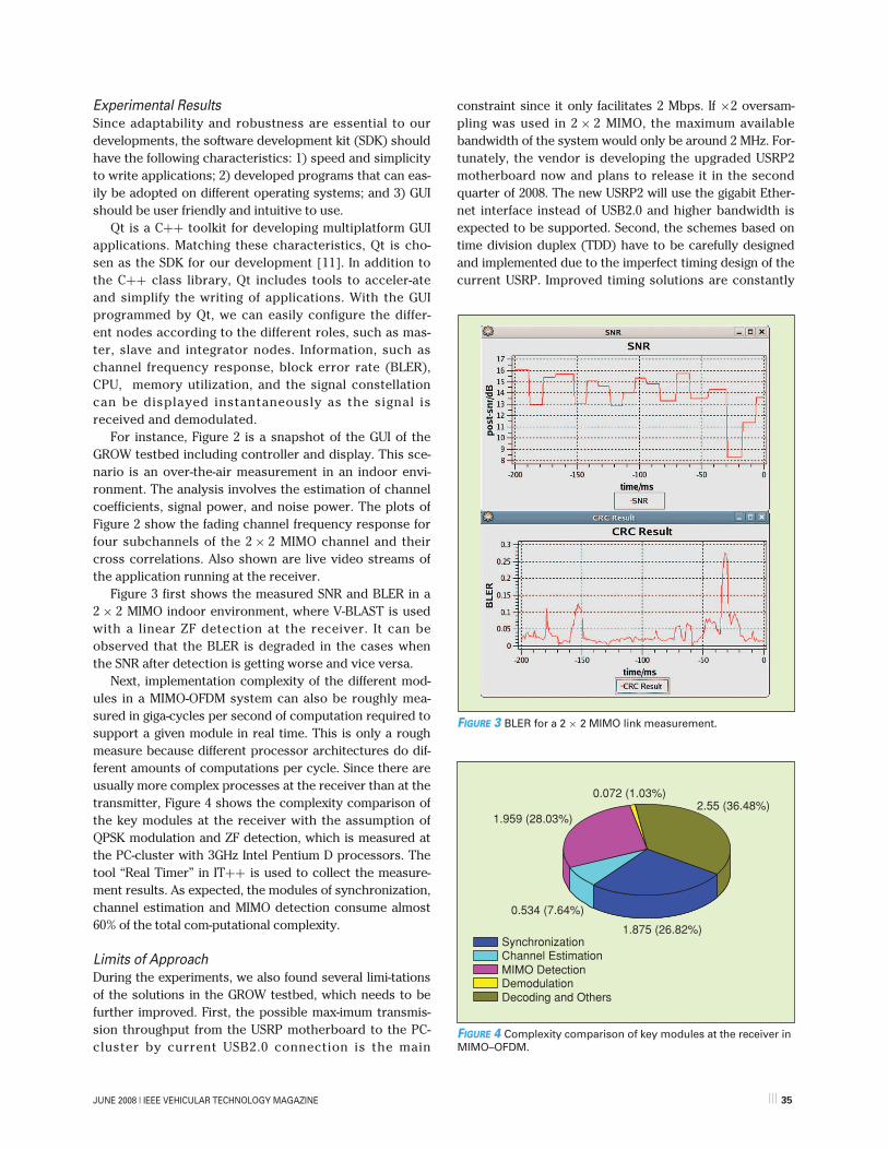
Figure 3 first shows the measured SNR and BLER in a2 × 2 MIMO indoor environment, where V-BLAST is usedwith a linear ZF detection at the receiver. It can beobserved that the BLER is degraded in the cases whenthe SNR after detection is getting worse and vice versa.
Next, implementation complexity of the different mod-ules in a MIMO-OFDM system can also be roughly mea-sured in giga-cycles per second of computation required tosupport a given module in real time. This is only a roughmeasure because different processor architectures do dif-ferent amounts of computations per cycle. Since there areusually more complex processes at the receiver than at thetransmitter, Figure 4 shows the complexity comparison ofthe key modules at the receiver with the assumption ofQPSK modulation and ZF detection, which is measured atthe PC-cluster with 3GHz Intel Pentium D processors. Thetool “Real Timer” in IT++ is used to collect the measure-ment results. As expected, the modules of synchronization,channel estimation and MIMO detection consume almost60% of the total com-putational complexity.
Limits of Approach During the experiments, we also found several limi-tationsof the solutions in the GROW testbed, which needs to befurther improved. First, the possible max-imum transmis-sion throughput from the USRP motherboard to the PC-cluster by current USB2.0 connection is the main
constraint since it only facilitates 2 Mbps. If ×2 oversam-pling was used in 2 × 2 MIMO, the maximum availablebandwidth of the system would only be around 2 MHz. For-tunately, the vendor is developing the upgraded USRP2motherboard now and plans to release it in the secondquarter of 2008. The new USRP2 will use the gigabit Ether-net interface instead of USB2.0 and higher bandwidth isexpected to be supported. Second, the schemes based ontime division duplex (TDD) have to be carefully designedand implemented due to the imperfect timing design of thecurrent USRP. Improved timing solutions are constantly
FIGURE 4 Complexity comparison of key modules at the receiver inMIMO–OFDM.
0.072 (1.03%)
1.959 (28.03%)
0.534 (7.64%)
1.875 (26.82%)SynchronizationChannel EstimationMIMO DetectionDemodulationDecoding and Others
2.55 (36.48%)
FIGURE 3 BLER for a 2 × 2 MIMO link measurement.
JUNE 2008 | IEEE VEHICULAR TECHNOLOGY MAGAZINE ||| 35

being made available through the efforts of the GNU Radiocommunity. Third, in order to support MIMO transmission,the clocks between the RFX2400 daughter boards and eventhe USRP motherboards need to be synchronized by addi-tional operations. For a 2 × 2 MIMO, the independent oscil-lator in each RFX2400 daughter board of the same motherboard is disabled and both of its clock signal provided bythe oscillator of the motherboard (as we had implementedalready). However, for more antennas, like 4 × 4 MIMO, theclock signals of the multiple motherboards have to be syn-chronized by selecting one of the motherboards as masterto output clock signal and the others as slave to be in linewith it. More hardware and software improvements forsynchronizing multiple USRPs are still under developmentby the GNU Radio community.
Conclusions and Outlook
The exposed platform is a first step towards utilizing aflexible SDR GNU radio to quantify the real-world perfor-mance of advanced over-the-air technologies, such as3GPP LTE-type MIMO OFDM systems. We have detailedthe hardware and software blocks, demonstrating that theplatform is indeed very flexible and versatile. Contrary toanalysis and simulations, this platform allows us to identi-fy problems and limits of current B3G algorithmic devel-opments as well as implementations by means of SDR.
In further developments, we will improve the platformto meet the requirements of higher throughput and evenmore flexibility. The testbed will also likely be opened tothe greater research community in the hope that opensource SDR developments will accelerate the deploy-ment of B3G systems by means of SDRs.
References[1] “Requirements for evolved UTRA (E-UTRA) and evolved UTRAN (E-UTRAN),
Release 7,” 3GPP TR 25.913 vV7.3.0 (2006-03). [2]E. Dahlman, H. Ekstr, A. Furuskar, Y. Jading, J. Karlsson, M. Lundevall, and S.
Parkvall, “The 3G long-term evolution-radio interface concepts and perfor-mance evaluation,” IEEE Commun. Mag., vol. 44, no. 3, Mar. 2006, p. 3845.
[3] J.J. Sanchez, D. Morales-Jimenez, G. Gomez, and J.T. Enbrambasaguas, “Physi-cal layer performance of long term evolution cellular,” in Proc. 16th IST Summit,2007, July 2007, pp. 1–5.
[4]X. Weidong, D. Waters, T.G. Pratt, J. Barry, and B. Walkenhorst, “Implementa-tion and experimental results of a three-transmitter three-receiverOFDM/BLAST testbed,” IEEE Commun. Mag., vol. 42, no. 12 pp. 88–95, Dec. 2004.
[5]X. Nieto, L.M. Ventura, and A. Mollfulleda, “GEDOMIS: A broadband wirelessMIMO-OFDM testbed, design and implementation,” in Proc. IEEE Testbeds andResearch Infrastructures for Development of Networks and Communities (TRI-DENTCOM) 2006, Barcelona, Spain, Mar. 2006.
[6]W. Tuttlebee, Software Defined Radio. Hoboken, NJ: Wiley, 2003.[7]Z. Sujian, S. Cong, S. Xin Su, and Y. Yan, “Architecture of a software radio sys-
tem based on cluster of workstations,” in Proc. IEEE Region 10 Int. Conf. Electri-cal and Electronic Technology (TENCON) 2003, 15–17 Oct. 2003, vol. 4, pp.1439–1444 .
[8]A. Betts, M. Hall, V. Kindratenko, M. Pant, D. Pointer, V. Welch, and P. Zawada,“The GNU software radio transceiver platform,” in Proc. 2004 Software DefinedRadio Technical Conf., Nov. 2004, vol. C, pp. 41–46.
[9] “Technical specification group radio access network: Physical layer aspects forevolved universal terrestrial radio access (UTRA) (R7),” 3GPP TR 25.814 V7.1.0(2006-10).
[10]Message Passing Interface Forum, “MPI: A Message-Passing Interface standard,”Int. J. Supercomputer Applications and High Performance Computing, 8, 1995.
[11]Trolltech, “Qt 4.3—Whitepaper,” Trolltech, 2007 [Online]. Available:www.trolltech.com/products/qt
Acknowledgment
This work is supported by Orange Labs, France TelecomR&D, Beijing, China.
Author Information
Kan Zheng ([email protected]) received the B.S., M.S.,and Ph.D. degrees from Beijing University of Posts andTelecommunications (BUPT), China, in 1996, 2000, and2005, respectively, where he is currently a lecturer.From 2000–2001, he was a system development engineerat TD-SCDMA R&D Center, Siemens, Ltd, in Beijing,China. He was also part-time researcher in Orange Labs,France Telecom R&D, Beijing, China. His currentresearch interests are in the field of signal processingfor digital communications, with emphasis on SDR andPHY/MAC algorithms in MIMO systems. He is a Memberof the IEEE.
Lin Huang received the B.S. and M.S. degrees fromBUPT, China, in 2002 and 2005, respectively. She cur-rently works at Orange Labs, France Telecom R&D, Bei-jing, China. Her current research interests are in thefield of SDR and cognitive/cooperative communicationschemes.
Gang Li received the B.S. degree from BUPT in 2005,where he is currently working toward the M.S. degree. Hiscurrent research interest is in the field of signal process-ing for SDR implementation.
Hanwen Cao received the B.S. degree from BUPT in2005, where he is currently working toward the M.S.degree. His current research interest is in the field of signalprocessing for SDR implementation and cognitive radio.
Wenbo Wang received his B.S., M.S., and Ph.D.degrees from BUPT, in 1986, 1989, and 1992, respectively.He is professor and dean of the School of Telecommuni-cation Engineering at BUPT. His research interestsinclude signal processing, mobile communications, andwireless network. He is a Member of the IEEE.
Mischa Dohler received his Ph.D. and M.Sc. intelecommunications from King’s College London, U.K. Hewas lecturer at King’s College London, Centre forTelecommunications Research, until June 2005. He isnow a senior expert in the R&D department of FranceTelecom working on cooperative communication sys-tems and wireless sensor networks. He has pioneeredresearch on distributed cooperative space-time encodedcommunication systems in the framework of the MobileVCE, dating back to December 1999. He has publishedmore than 100 technical journal and conference papersat a citation h-index of 10 and citation g-index of 22,holds several patents, coedited and contributed to sever-al books, and has given numerous international shortcourses. He has been TPC member and cochair of vari-ous conferences, is technical chair of IEEE PIMRC 2008,and is editor for various journals and magazines. He is aSenior Member of the IEEE.
36 ||| IEEE VEHICULAR TECHNOLOGY MAGAZINE | JUNE 2008