kandidat - diva portal668630/fulltext01.pdf · cctv – closed-circuit ... figure 1. example of a...
TRANSCRIPT

KA
ND
IDAT
UPPSATS

Using Network Attached Storage for IP-Surveillance
Bottleneck analysis and developing a method for testing Network Attached Storage performance for IP-surveillance
Bachelor Thesis
June 2013
Author: Joakim Nymberg
Supervisor: Tomas Nordström
Examiner: Urban Bilstrup
School of Information Science, Computer and Electrical Engineering
Halmstad University PO Box 823, SE.301 18 Halmstad Sweden

I
© Copyright Joakim Nymberg 2013. All rights reserved Bachelor Thesis School of Information Science, Computer and Electrical Engineering Halmstad University

II
Acronyms
CCTV – Closed-Circuit Television
DVR – Digital Video Recorder
DAS – Direct Attached Storage
DMA – Direct Memory Access
LAN – Local Area Network
NAS - Network Attached Storage
NCQ – Native Command Queuing
NIC – Network Interface Card
PoE – Power over Ethernet
RAM – Random Access Memory
RTCP – Real Time Control Protocol
RTP – Real Time Transport Protocol
RTSP – Real Time Streaming Protocol
SMB/CIFS – Server Message Block/Common Internet File System
SAN – Storage Area Network
SOHO – Small Office, Home Office
TCP – Transfer Control Protocol
VCR – Video Cassette Recorder
VMS – Video Management Software
QoS – Quality of Service

III
Acknowledgements
First and foremost I want to thank Karl Rosendahl and Patrik Jansson and the other employees at Axis for making me feel welcome and giving me the opportunity to write my thesis in cooperation with Axis.
I also want to thank my supervisor for giving me guidance and advice during the process of writing this thesis.
During the process of writing and experimenting I have encountered a multitude of problems and stumbled upon new, both related and unrelated knowledge, in areas I probably never would have set my foot in it wasn’t for this thesis. To sum it up, I’ve learned a lot.
Last but not least I want to thank my girlfriend for bearing with me and giving me advice when I felt I was stuck both during the writing process and how to approach problems encountered.

IV

V
Abstract
IP-surveillance systems are surveillance systems designed to send video and audio over IP-networks, to be able to function a typical system consist of IP-cameras to record footage, a client to view footage and recordings, network hardware to send the data, protocols to administer storage and viewing operations and last but not least a location to store the captured data. One of the options for storing surveillance video is to use a Network Attached Storage. Axis has received customer cases reporting lost footage and cameras losing their connection when using NAS-devices as storage in IP-surveillance systems.
This thesis aims to investigate what a NAS is and how it interacts with cameras in an IP-surveillance environment by analyzing the protocols and components being used and by performing experiments to locate the system bottleneck causing these problems. After concluding that the hard disk drive was the bottleneck because of the overload imposed on the other components by the incoming data traffic and how data is moved and temporarily stored in a system. Recommendations of possible ways to remedy these problems were suggested with the proposed problem of solving the bottleneck problem was to add more disks to improve performance, this was the second aim of the thesis, which sadly was not possible because of the 2-bay NAS systems being used in the tests. The third and final aim was to establish and develop method guidelines for testing NAS-systems. This was done by using previous research in the area and using data encountered when trying to locate the bottleneck.

VI

VII

VIII
Table of contents
1 Introduction ....................................................................................................................... 1 1.1 Problem.................................................................................................................................... 2 1.2 Limitations .............................................................................................................................. 2 1.3 Related Work ......................................................................................................................... 3 1.4 Background ............................................................................................................................ 4
1.4.1 Video Surveillance .......................................................................................................................... 4 1.4.2 Network Attached Storage ......................................................................................................... 5
1.5 Structure .................................................................................................................................. 6
2 Method ................................................................................................................................. 7
3 Components ....................................................................................................................... 9 3.1 Hardware components ....................................................................................................... 9
3.1.1 Network attached Storage .......................................................................................................... 9 3.1.2 IP-cameras ...................................................................................................................................... 10 Axis Cameras ................................................................................................................................................. 10 3.1.3 Hard Disk Drives .......................................................................................................................... 12 3.1.4 Switches and Routers ................................................................................................................ 12 3.1.5 Client ................................................................................................................................................. 13
3.2 Software components ...................................................................................................... 13 3.2.1 SMB/CIFS ........................................................................................................................................ 13 3.2.2 RAID 1 .............................................................................................................................................. 14 3.2.3 Video Management Software .................................................................................................. 14 Axis Camera Companion .......................................................................................................................... 14 3.2.4 The RTPS and RTP/RTCP protocols .................................................................................... 15
3.3 Understanding video compression ............................................................................. 16 3.3.1 The h.264 format ......................................................................................................................... 17
4 Locating the NAS performance bottleneck .......................................................... 20 4.1 Hard Disk Drive test ......................................................................................................... 20
4.1.1 Test setup ....................................................................................................................................... 20 4.1.2 Test results ..................................................................................................................................... 21
4.2 NAS performance tests .................................................................................................... 21 4.2.1 Test setup ....................................................................................................................................... 22 4.2.2 Setup for 8 cameras .................................................................................................................... 23 4.2.3 Hardware added and changes done for the 16 camera setup .................................. 24 4.2.4 NAS configurations and SMB copy performance. .......................................................... 25 4.2.5 Testing and collecting procedure ......................................................................................... 26 4.2.6 NAS performance Results ........................................................................................................ 27
5 Improving performance ............................................................................................. 34
6 Testing Methods ............................................................................................................ 35
7 Discussion and future work ...................................................................................... 37
8 Conclusion ....................................................................................................................... 39

IX
Table of figures
Figure 1. Example of a typical IP-camera installation using NAS to record footage ........................................... 1
Figure 2. Flowchart describing the USE method ................................................................................................................. 8
Figure 3. File level data flow through a NAS ........................................................................................................................ 9
Figure 4. 8 camera setup network topology ...................................................................................................................... 23
Figure 5. 16 camera setup network topology .................................................................................................................... 24
Figure 6. Display of the correlation between amounts of data transfers and CPU usage, along with showing the increased amount of data received during nighttime. ......................................................................... 27
Figure 7. Graph of one of the shorter tests with a high degree of human movement on the TS-219PII NAS ............................................................................................................................................................................................................. 28
Figure 8. Graph of the TS-212 during a test performed with a high degree of human movement. ............. 29
Figure 9. Graph of disk utilization of the two physical hard drives during the same test session. ............... 29
Figure 10. Network during the same test session as referred to in the Figure 6 and 7. ................................... 30
Figure 11. Block sizes being requested to be written to the two physical hard drives by the network adapter. ............................................................................................................................................................................................ 31
Figure 12. Memory consumption during the test that failed ...................................................................................... 32
Table index
Table 1. Table displaying the resolution capabilities of cameras depending on the last number in its naming structure .......................................................................................................................................................................... 11
Table 2. An example of different bitrates depending on H.264 levels, profiles, resolutions and frames per second................................................................................................................................................................................................ 18
Table 3. The manufacturers hard drive disk specification. .......................................................................................... 20
Table 4. HD Tune Pro 5.0 throughput test results. .......................................................................................................... 21
Table 5. IP-Cameras used for the 8 camera setup along with resolution and FPS settings ............................ 23
Table 6. IP-Cameras used for the 16 camera setup along with resolution and FPS settings.......................... 24
Table 7. The NAS systems tested and their specifications. ........................................................................................... 25

X

XI

Using Network Attached Storage for IP-Surveillance
1
1 Introduction
IP-surveillance is a digitized surveillance system created to record and view footage on Ethernet connected cameras called IP-cameras. When using IP-cameras to record footage there are a few required components such as, a Video Management Software (VMS) to watch live views and possible recordings, a switch or router or both depending on how many cameras are required and finally cables to connect the cameras. To watch the footage after recording a storage device has to be employed. This is where Network Attached Storage comes in.
Network Attached Storage (NAS) is a way of sharing data on a file level to multiple clients on a particular network and was born in the early 1980’s. Since the systems creation a growing NAS market has evolved and the now multiple NAS systems segments ranging from home and small office use to rack mounted enterprise class systems. NAS and other types of systems were originally created to simplify backup and sharing data to multiple machines to optimize storage volumes [1,2]. Currently home and small and home office users are more than often using their NAS systems to back up files or stream video or audio.
Considering that many of the camera installations in the IP-surveillance market are labeled as small (sub-16 cameras) [3]. With a big market share provided by these smaller installations a few actors in the IP-surveillance market, namely Axis Communications and Mobotix developed free software to control and manage smaller camera installations using their own respective cameras; and in these Video Management Software making it an option to record surveillance footage to NAS systems. In Figure 1 a depiction of a typical IP-camera installation using NAS to record surveillance footage can be viewed.
Figure 1. Example of a typical IP-camera installation using NAS to record footage

Using Network Attached Storage for IP-Surveillance
2
1.1 Problem
There are several quality and performance differences in today's NAS market both depending on manufacturer and price segments. Because of this, it cannot be guaranteed that all NAS models and manufacturers meet the current demands needed to support IP-cameras; therefore it is desirable to somehow be able to determine if a specific model meets the minimum requirements to be used for a specific quality of recording and amount of cameras desired customers.
Several Axis customers have been reporting crashes or lost footage using cameras along with NAS-systems. The goal of this thesis is to take a closer look on how a NAS works along with IP-cameras. An analysis of the factors that affect the throughput needed for the NAS. The IP-camera streaming and storage protocols and how it communicates will also be analyzed to give a better understand of how IP-surveillance works. The thesis will use research along with experiments to try and uncover the problem with IP-cameras and NAS systems and if it is possible; specify a certain bottleneck component in the system. After doing this the data collected will be evaluated to give advice on what might improve performance and to develop a method for testing cameras in future evaluations of NAS systems.
The goals of the thesis are:
Locate the bottleneck for the NAS as a storage media along with IP-cameras using experiments and previous research.
Give suggestion on what might improve performance.
Give guidelines on developing a method for testing cameras against NAS systems.
1.2 Limitations
This work will be done in a controlled environment to determine the performance issues associated with ACC (Axis Camera Companion) in a NAS storage setup with a flexible amount of cameras and recording specifications using the h.264 format. Axis cameras and Axis Camera Companion will be used to manage and configure the cameras.
The focus in this thesis is on so called SOHO (Small Office, Home Office) grade 2-bay NASes using RAID level 1 with default configuration and NAS-oriented or enterprise disks. While there are a multitude of parameters that could be considered like camera vendor, NAS price range, camera managing software and different types of network file systems, these variables are far beyond the scope of this paper.

Using Network Attached Storage for IP-Surveillance
3
1.3 Related Work
There has been some work done in the field of NAS-storage and performance measuring. Deng’s Deconstructing Network Attached Storage Systems [4], explained the data flow through a NAS and tried to determine the bottlenecks of NAS by testing each part individually with different types of benchmarking software. While, this is a perfectly valid way of trying to determine the bottleneck in a system, the tests performed by Deng used a Intel Xeon 3.2 GHz dual core processor and levels of RAID to improve disk performance, Intel Xeon CPUs is a type of processor used in server grade systems and is considerably more powerful than the CPUs found in current SOHO NAS-systems. Deng pinpointed the network as the limiting factor when measuring performance in NAS-systems.
Prior to this Sarkar et al. investigated the possible bottlenecks in IP-storage systems, which included DAS and SAN systems apart from NAS; in both IP-storage: The Challenge Ahead [5] and later on in Storage Over IP: When Does Hardware Support Help? [6]. In the first paper mentioned, Sarkar concluded that the CPU was the main bottleneck due to the large overhead provided by the TCP copy-and-checksum and interrupts provided by transfers for large block sizes. These interrupts can be reduced by using jumbo frames and in that way limit the interrupts needed per transfer. In his following thesis it was concluded that hardware support helped for transferring large block sizes, in the other tests it was concluded the added performance of hardware support was negligible because of the current computing power provided by CPUs.
Some work has also been done with regard to NAS benchmarking. One important tool is the creation of Intel's NASPT [7] exerciser and visualizer. Previous to Intel's software being released, instead of using a tool to exercise the NAS as a standard system would, multiple synthetics test where run on the system for testing the individual parts but not testing all the parts in unison. While all of the tests are a good way of determining the capacity of a NAS they actually don't pinpoint where the bottleneck is located in the systems tested.
The NASPT tests would still not give a complete representation in regards to how many IP-cameras could be connected and where the bottleneck is located within the NAS. Since the video format used is variable bit rate format there is currently no tests except observing and logging in real time and then analyzing the logs to try and determine the bottleneck.
The only similar work that has been done with testing cameras together with NAS-systems and how it affects the system in both long-term and short-term, largely with the regards of frame loss and recording quality has been done by a company named Intransa, Intransa is also an actor in the video surveillance market. While these papers released by Intransa[8,9,10] are whitepapers and they investigated the behavior of NAS-systems along with IP-surveillance.. Intransa attributed the frame loss in recorded footage to hard drive queue depth and latency. The large amount

Using Network Attached Storage for IP-Surveillance
4
and constant writing on the hard drives also shortened the potential life time of the disks.
1.4 Background
The evolution and increased use of surveillance in our society has grown in recent years. This chapter is reserved for taking a closer look on the evolution of both the NAS systems and IP-Surveillance.
1.4.1 Video Surveillance
Video surveillance or Closed-circuit television (CCTV) was first introduced and created for the purpose of observing V-2 rocket launches in the Second World War. The first system was created by Siemens[11].
In 1967 in United Kingdom a company called Photoscan launched the first CCTV system aimed for the retail market; the product was marketed for preventing and catching shoplifters. In 1975 cameras started appearing in the public space, cameras were installed to both prevent congestion and prevent accidents in traffic as well as to prevent crime. Between 1994 and 2002 there was an exponential growth in installed CCTV, related to both the spiraling crime rate and a few individual gruesome crimes noticed by the media [12]. In 2002 the estimated amount of CCTV cameras in London was around 500 000 and the total number of cameras in the UK alone to 4 200 000[13].
On the other side of the Atlantic the first reported use of CCTV cameras was in 1949 by a company named Vericon. It was used to monitor dangerous industrial processes and demonstrations of surgical operations [14]. Other early cases of CCTV usage were in1968 in the city of Olean in the state of New York to deter and prevent crime. Another installment was done by the New York Police Department in Times Square, New York in 1973 for the same reasons. In the 1980’s with the emergence of cheaper technology CCTV was seen as a cheaper solution to prevent and deter crime compared to expanding the police departments and therefore the amount of CCTV system were increased [11]. After the terrorist attacks on the twin towers 11th of September 2001 in New York the amount of surveillance system installed have grown at ever growing rate [15]. With the more recent Boston Marathon bombings there is no reason to believe any change regarding this trend [16].
To the authors knowledge the first IP-cameras saw the emergence in 1996 with the Axis NetEye 200 released by Axis Communications. IP-cameras send data digitally over the LANs (Local Area Networks) as opposed to previous types of video surveillance where footage was sent and stored analogously to DVRs (Digital Video Recorders) or VCRs (Video Cassette Recorders). IP-camera systems have the potential to provide higher quality footage compared to analogue variants of the system.

Using Network Attached Storage for IP-Surveillance
5
In today's society video surveillance is becoming increasingly common, both in public and private management. With increased bandwidth and network capacity available in most parts of the world to meet the demands for both streaming video data over the Internet and over a LANs, while PoE (Power over Ethernet) have become increasingly common and cheap, thus making the concept of separate cables for video streaming and supplying electrical power redundant.
The video surveillance market was projected a 19.35% annual growth rate from 2011 to 2016 while the market is also shifting to IP-based surveillance during the same period [17]. The small camera installations (16 cameras or less) constitute to half of the surveillance market [18]. 2013 is also the year where IP surveillance installations are projected to surpass the analog surveillance share of the market [19].
1.4.2 Network Attached Storage
Network Attached Storage was first developed in the 1980’s as an alternative network storage method to Direct Attached Storage (DAS) and Storage Area Network (SAN). It was introduced as a storage solution with easier configuration and administration compared to the storage options.
NAS systems are directly connected to a network as opposed to the DAS that does not need to be networked and SAN that is connected to a network but only serve files on a block level basis.
NAS systems have become increasingly popular on both the home and enterprise market in the last couple of years with differing market segments and a multitude of vendors competing for customers. A NAS is similar to an ordinary computer from a hardware point of view; the exception is that they have no peripherals or a graphic card. Management of the NAS is usually done via SSH/Telnet or a Web Interface or a combination of both. The systems designed for home use are usually small form factor boxes differentiating them from their rack mounted enterprise counterparts.
Many of these systems are run on an embedded version Linux and specific processors designed for these embedded systems. There is a multitude of uses for a NAS, the NAS can be used as a normal fileserver, hosting a database, a webserver or as described here use it to storage surveillance footage [20].
There are many different vendors competing for marker shares and here are a few of the more popular ones: Qnap, Netgear, Buffalo, Lacie.
Using Network Attached Storage for IP-Surveillance
6
1.5 Structure
This thesis is divided into eight chapters, this first chapter introduced the concept of IP-surveillance, problem statement and background. Chapter two describes the methodological approach and related work. Chapter three focuses on the necessary hardware and software components of an IP-surveillance system. It also describes the protocol and formats being used in this particular setup and how data communication works between the NAS, client and camera. Chapter four defines the experiment test bed and components being used in the experiments as well as the software used for recording data and a conclusion, after describing the setup the associated results will be presented. The fifth chapter is about how performance can be improved. The three final chapters present recommendations and guidelines for new testing methods, future work and discussion and in the final eighth chapter the thesis is concluded.

Using Network Attached Storage for IP-Surveillance
7
2 Method
In this chapter the choice of method and how the experiments will be executed will be explained. It is important to note that the results in this experimental method should not be viewed as proof, but rather give an indication on what might be the problem or solution portrayed in the problem section. [21] Despite this limitation, this method was chosen to be the most suited for this type of thesis.
Before executing the tests a rundown of the physical components, software and the protocols required for this specific IP-surveillance system to work will be explained.
There will be two different types of tests conducted with the different NAS configurations; the first test is a longer running multiple hours capturing footage while also playing back footage regularly to see if any problem starts occurring. The other experiment will be done by capturing data in shorter intervals consisting of a few minutes with a high amount of movement in the area and see how the NAS reacts. Parameters, settings and criteria’s for the experiments are explained below. In the construction and the following analysis, and development of testing methods Jains - Art of Computer System Performance Analysis Techniques for Experimental Design Measurements Simulation and Modeling [22] was used as a guideline.
The experiments will be executed on three different NAS models with varying hardware configurations while monitoring the performance of the NAS-systems. For the purpose of the tests executed the maximum settings for the cameras will be used, to put as much as strain as possible on the NAS.
After conducted experiments analyzing the output generated from the chosen monitoring tool and examining the camera logs for error messages. Along with examining the recorded footage captured by the cameras and recorded to the NAS. All of these variables along with playing back the captured footage with the provided VMS will be the determining factor deciding if there is a problem with the given setup.
To pinpoint performance problems the USE method will be used. The USE method was developed by Brendan Gregg [23] from the lack of methodical systems to determine system bottlenecks and performance issues in systems. Brendan is a former employee of Sun Microsystems and the author of DTrace: Dynamic Tracing in Oracle Solaris, Mac OS X and FreeBSD[24]. Dtrace is a widely used performance framework created for troubleshooting and performance monitoring.

Using Network Attached Storage for IP-Surveillance
8
The USE method approach for locating performance problems is to break down the hardware components in a system, testing utilization, saturation and errors, component by component. In this thesis focus will be on the four components identified by Deng [4] as the main performance components in a NAS; CPU, memory, network and storage media. Below (Fig.2), is an example diagram depicting the work flow using the USE method. In this thesis the resources identified are network, CPU, memory and storage media. These resources will be monitored and analyzed to determine the bottleneck in the system.
Figure 2. Flowchart describing the USE method
The current method of testing NAS systems as a storage media for camera surveillance footage at Axis Communications is by using the desired amount of cameras to be tested and aim the cameras at a computer screen with a software running that activates the motion detection at regular intervals. This system in then run over several days while monitoring the load on the systems processor and the disk usage used by the system [25].

Using Network Attached Storage for IP-Surveillance
9
3 Components
A system for recording camera surveillance contains a number of hardware components, both for recording footage, storing the recordings, playing back the recorded footage as well as devices to enable communication between these components.
There are also software components needed to facilitate communication between these devices; protocols to communicate how to store the data being recorded from the cameras and how to stream the data to the client and the supplied Video Management Software. To provide redundancy a RAID 1 volume manager is used in case of hard drive faults.
3.1 Hardware components
The components listed in the following are the hardware components used and needed in a typical IP-camera installation. The components needed are an IP-camera or cameras to record, a computer to view live footage a NAS to record the video data, a computer for viewing live footage and a switch or router (or both) to facilitate communication between the devices.
3.1.1 Network attached Storage
The main components limiting the NAS throughput was by Deng identified as CPU, memory and storage media as well as the network bandwidth [4].
To be able to determine the possible limiting factors of a NAS a breakdown of the components and the flow of data from when data arrives at the NIC (Network Interface Card) and to when it finally gets written to the disk on the NAS is necessary. A NAS uses both the TCP/IP and Storage stack in its operations. Network Attached Storage systems utilize both the networking and storage subsystems therefore it inherits all problems and limitations attributed to these systems [26].
A NAS can share files to other computers via either a block level file system like iSCSI, or via a network file system. iSCSI
Figure 3. File level data flow through a NAS

Using Network Attached Storage for IP-Surveillance
10
shares data directly via TCP/IP packets and the TCP/IP network which limits the overhead compared to sending data via TCP/IP. A depiction of the data flow of a NAS using SMB, RAID 1 and ext4 as its file system can be seen in figure 3.
The second option is supplying data to clients through a network file system, either through CIFS/SMB (Common Internet File System/Server Message Block) or NFS (Network File System). It doesn't matter what virtual file system is being utilized, the flow of data through the NAS is still exactly the same, the network file system just transfers of data in a different way, the use of a SAMBA server to negotiate information and transfer data is required when using the protocol
SMB/CIFS can be described as a high-level network protocol for sharing and transferring files by sending (RPC) Remote Procedure Calls. The protocol also has a multitude of other uses but these are not relevant in this thesis. A more detailed discussion on how SMB/CIFS work will be discussed later on in section 3.2.1.
After getting authentication from the server the data is sent through the VFS (Virtual File System) and gets processed by the file system residing on the system in question. The file system then passes the data through the Logical Volume Manager if one exists. In this case we are using RAID 1 which will also be discussed and described in the following chapter.
When reads occur on the NAS the dataflow of the NAS reverses direction, but only if the data that is requested does not already reside in the memory cache. If the data requested does not reside in the cache the data needs to be fetched from the disks and processed through the disk controller (in this case SATA). The data is then sent to the system bus and by the end it gets fragmented into IP-packets and sent through the network to the system requesting the data[4].
3.1.2 IP-cameras
A network camera (or IP camera) is a camera designed to send mainly video but can also send audio over a network, either a LAN (Local Area Network) or over the Internet. An IP-camera can be described as a merger of both a computer and a camera. Just as a normal computer the camera has its own processor or even multiple, processors, memory and file system. Every camera has to have its own assigned IP and MAC address just as every other network connected peripheral [27]. The most important performance features in an IP camera from the end users point of view is usually video resolution, frame rate and compression ratio. All of these features are limited by the processing power in the camera [28].
Axis Cameras
Axis cameras are powered by the proprietary ARTPEC-chip, the chip contains a CPU and a coprocessor that takes care of all calculations for encoding the captured images and I/O transfers needed on the embedded Linux platform running on the cameras. Axis IP-cameras contain a multitude of other features besides just
Using Network Attached Storage for IP-Surveillance
11
recording video, extra functions like motion and audio detection, FTP servers and e-mail functionalities when events are triggered are futures supported by some camera models. Each camera also has its own NICsupporting 100mbit/s [27].
Axis works extensively with third party developers, who are able to integrate Axis cameras in their own software solutions. This is provided with Axis own application programming interface (API) named VAPIX®. The API was created to make it easier for developers and to create a standard system for calling specific functions on the cameras. The most recent version of VAPIX® is version 3 and it’s compatible with camera firmware 5.xx. All features of the camera are accessed via the VAPIX® API.
Axis cameras can also be accessed and managed using HTTP/HTTPs. Options available in the web-interface are frame rate, compression format and rate (H.264/Motion JPEG), user access, firmware updates, time/date with either an NTP server or the local systems date and time. The time and date control the naming of recorded files for the camera Axis cameras use SMB/CIFS to store data on remote storages and the RTSP protocol to stream video and audio data to clients[29].
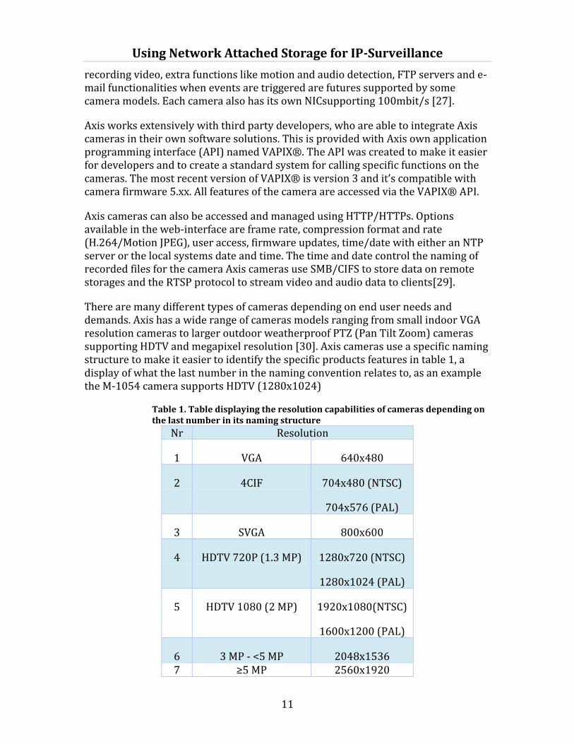
There are many different types of cameras depending on end user needs and demands. Axis has a wide range of cameras models ranging from small indoor VGA resolution cameras to larger outdoor weatherproof PTZ (Pan Tilt Zoom) cameras supporting HDTV and megapixel resolution [30]. Axis cameras use a specific naming structure to make it easier to identify the specific products features in table 1, a display of what the last number in the naming convention relates to, as an example the M-1054 camera supports HDTV (1280x1024)
Table 1. Table displaying the resolution capabilities of cameras depending on the last number in its naming structure
Nr Resolution
1 VGA 640x480
2 4CIF 704x480 (NTSC)
704x576 (PAL)
3 SVGA 800x600
4 HDTV 720P (1.3 MP) 1280x720 (NTSC)
1280x1024 (PAL)
5 HDTV 1080 (2 MP) 1920x1080(NTSC)
1600x1200 (PAL)
6 3 MP - <5 MP 2048x1536 7 ≥5 MP 2560x1920

Using Network Attached Storage for IP-Surveillance
12
3.1.3 Hard Disk Drives
Hard Disk Drives are used in the NAS to store recorded footage. Hard Drive disks were developed in the 1980’s by IBM and in the 1990’s a common standard interface was developed for hard drives named Advanced Technology Attachment (ATA). Since then there has been a constant evolution of standard interfaces, the current standard is named Serial ATA (SATA), with the version of SATA, version 3 supporting up to 6 Gbps or 600 MBps.
Hard Disk Drives are mechanical and store data in small magnetic fields called fluxes, the techniques of storing data has become more and more advanced since the arrival of hard drives and these techniques along with the small magnetic fields called fluxes becoming smaller and smaller are what increases the capacity of the hard disk drive.
Physically the hard drive consists of platters where every platter has two arms called actuator arms to execute the reads and writes of the hard drive. All these components are sealed in to prevent contamination. The geometry of the hard drive is defined by three factors: cylinders, heads and sectors per track or CHS. The cylinder is a track spanning over all platters of the drive, sectors are the smallest piece of data that can be written on a hard drive and are usually 512 bytes[31], the last few years developers have introduced sectors sizing 4096[32] bytes as well. Sectors per track indicate how many sectors every track consists of.
Drive speed in mechanical drives are measured by RPM (Revolutions Per Minute) ranging from 3,600 and 15,000, in terms of storage space the capacity is nowadays measured in TB or Terabytes (1012bytes) [30]. Mechanical hard disk drive sizes are increasing by 20-25% per year and by the year 2016 12 TB drives are projected to be the standard hard drive size in desktop machines [33].
3.1.4 Switches and Routers
Routers and switches are two very integral components of IP-networking functionality. The router is usually assigned to send data between networks as well as the internal network. A switch on the other hand only sends data on the LAN in question
A router has the task, as the names device name suggests, to route IP-traffic received by the device to the next network, based on the matching IP-address located in the internal routing table. Each router sends the packet or packets onwards between networks until it reaches its final destination. Routers operate on layer 3 of the OSI-model (Open System Interconnection), which means that it locates its destination by the IP-address.

Using Network Attached Storage for IP-Surveillance
13
Switches operate at layer 2 of the OSI-model and identify its connected devices by a MAC-address (Media Access Control). The MAC-address along with its associated port is recorded in the CAM table (Content Addressable Memory), every packet is then checked for a matching MAC-address to send the packets to its destination. When an address not present in the MAC-table is recognized by the switch it sends an ARP-request packet (Address Resolution Protocol) to all ports on the switch and then records the address of the respondent in the CAM table [34].
Power over Ethernet (PoE) is a means of supplying power to network devices with Ethernet cables. It makes separate power cables redundant for devices supporting this type of power supplying. It is usually used for low powered devices like IP-cameras and IP-telephones with 15.40 watts available for normal PoE and 25.50 watts for the newer PoE+ [35].
3.1.5 Client
The surveillance client could be any computer with the VMS (Video Management System) installed; this thesis only uses one computer as a client for viewing data. There is possibility that more than one client could be streaming the data recorded on the NAS. If multiple computers would be used as clients the amount data read from the NAS would be much greater. The particular software being used is directed at smaller camera installations so the author came to the conclusion that using more than one client would not be used to a great extent.
3.2 Software components
Down below the software components in an IP-surveillance setup along with the protocols being used will be discussed and introduced.
3.2.1 SMB/CIFS
SMB/CIFs [36] are as mentioned before a client and server based protocol, SMB works on the application and presentation layer of the OSI-model. Which means it relies on another protocol to carry it between client and server, the most common application is NetBios over TCP (NBT) or directly over TCP/IP? This means that the client sends a RPC (Remote Procedure call) command to the server, the server then executes the command provided by the client if the client in question has sufficient permissions to execute the command.
There are some performance issues with using SMB, in particular the NetBios implementation; this is also the version that the Axis cameras use for managing file transfers to the NAS. This issue is attributed not to the SMB protocol but to overhead provided by NetBios when broadcasting for clients at the startup. It also has some limitations compared to later versions of the protocol, among the more prominent ones are that version 1 is the so called “chattiness” of the protocol; this shows itself as having to negotiate and send more response compared to later versions of the protocol. This was abandoned in later versions by being able to

Using Network Attached Storage for IP-Surveillance
14
pipeline commands instead of having to send a response for every request compared to version 1 where the server had to get a response for every request it made to the client. Version 2 also increases the size of data blocks the protocol can send from 62 to 128; this improves performance when sending large files over the network [37].
3.2.2 RAID 1
RAID or Redundant Array of Independent Disks (originally Redundant Array of Inexpensive Disks) is a manner of dealing with the limits of the current I/O disk subsystem which is considered one of the major bottlenecks in system performance [38].
There are different levels of RAID, they either try and provide better performance or redundancy or in some cases both. RAID 1 also called mirrored array provide redundancy but at the cost of total disk space is divided by two.
There are very slight performance benefits from running a RAID 1 system, this is attributed to having two identical disks, and this allows the system to choose the disk with the shorter seeking, queuing and delays to service the data [39]. The drawbacks are in the case of failure when one of the disks requires rebuilding which provides more work for the CPU and could provide a bottleneck [38].
There are both hardware and software implementations of RAID. A software implementation of RAID is implemented in the system kernel while a hardware RAID is implemented by using an external hardware controller. This expansion chip has its own processing unit to offload the main systems processor when dealing with the RAID operations. Hsieh et al. came to the conclusion that while there was a disparity between hardware and software raid, the difference was negligible except for write operations with file synchronization [40].
3.2.3 Video Management Software
A VMS (Video management Software) is a type of software used to control, manage and view camera settings; view recorded video sessions and watch live feeds provided by the cameras. Every camera vendor has their own type of software or softwares depending on size and complexity of the system installed.
AXIS Camera Companion
AXIS Camera Companion (ACC) is a VMS created by Axis Communications for managing, viewing and controlling up to 16 Axis cameras. The software is intended for small or home offices, hotels and retail stores. The software can be downloaded from the Axis website free of charge. ACC automatically finds existing cameras on the current network and lets you manage where the recorded footage is stored; the current options are to save recorded footage on a Network Attached Storage or on a SD/SDHC/SDXC card. The option of storing data on a local storage media when the

Using Network Attached Storage for IP-Surveillance
15
network link fails is currently not implemented but it is planned in a future firmware release.
There are two different types of recording modes available in ACC, continuous and motion detection. Continuous sends a constant stream of data from the camera with the configured resolution and frame rate. Motion detection records when the camera is triggered by movement in its field of view, the sensitivity of the trigger can be adjusted. ACC exclusively uses the H.264 format for viewing, recording and playing back video streams [41].
3.2.4 The RTSP and RTP/RTCP protocols
Axis cameras use the RTSP (Real-time Streaming Protocol) as defined in RFC2326 to set up and negotiate audio and video sessions. RTSP along with two RTP and RTCP protocols are used to send audio and video data over networks.
The RTSP operate on port 554 protocol and requires a server and a client, similar to the SMB and other server/client protocols. In this setup the camera acts as a server and the VMS acts as a client. In the case of playing back recorded footage from a NAS, the VMS act as a client.
RTSP uses commands such as play and pause similar to a VCR to control media streams from the server (in this case the camera). The RTSP protocol also has the added functionality of being able to control resolution, bandwidth, compression and text overlay settings, these are just some examples of the functionalities.
RTSP in itself is not used to stream the actual video data between the client and server; instead two other protocols are used. One even numbered port is set up for RTP and the following odd numbered port is being used for RTCP (RTP Control Protocol) data [42]. The packets on the even numbered ports containing the media are sent using the RTP protocol. The RTP protocol was developed by IETF (Internet Engineering Task Force) and the Audio Video Transport Working Group and are defined in RFC3550.The protocol defines the standard format of sending RTP data and provides compensation for jitter and out of sequence data. The RTP packet contains variables such as quality of the video and audio being sent, timestamps and sequence number.
RTP’s sister protocol on the odd numbered port is named RTCP also defined in RFC 3550, RTCP sends data on the subsequent odd numbered port to control QoS (Quality of Service) and to synchronize the media streams. The traffic added by RTCP compared to RTP is relativity small (ca 5%) compared to the overall RTP traffic.
Every stream of media data is negotiated separately, so in the case of sending both audio and video, each individual stream is set up independently. This makes it possible to turn off audio but not video and vice-versa. RTSP can also be set up to be tunneled over http [43].
Using Network Attached Storage for IP-Surveillance
16
Viewing live stream from a camera
The VMS sends the play command to the RTSP server located on the camera, the RTSP server negotiates a port number for the RTP and RTCP packets for the stream supplied by the camera. The server sends back the captured footage to the IP address and specified port numbers which is then played back on the VMS. The profile type supplied by the camera stream is specified in the RTP packet.
Recording footage from the cameras
When a camera site is created using the supplied VMS a network share or storage media has to be assigned to every camera for recording. In the case of using a NAS a storage path must be specified pointing to an existing network share. When using quotas to limit the storage a valid username needs to be supplied and in the case of using a password protected share that has to be provided as well. The user assigned to the camera also has to have write permissions on the network share and preferably read for playing back recordings.
The authentication, transfer and writing of the data is communicated over the SMB/CIFS protocol. The camera checks if it has sufficient camera write privileges by sending a call to the NAS. If the camera has the sufficient permissions for writing to the network share the camera creates a database file on the NAS. In this file the camera stores the ID and the start and stop time of the recording/s. This data is used for keeping track of the recordings being saved for later playback [44].The files of the recorded footage are stored in the Matroska (mkv) format [45].
Playing back recorded footage
When accessing and playing back the recorded the footage using the VMS, the camera first checks if there is a database entry for the recording ID or IDs and a start and stop time for the recording in question by issuing an RTSP API play call. If a recording exists the camera sets up an RTSP session with the VMS. The camera regards the network share as a mounted share; it accesses the file on the NAS according to the SMB/CIFS credentials and then the camera plays back the recorded footage to the VMS and displays it on the client computer.
There is a reason for implementing the playback function in this manner. Instead of needing to have access to the NAS when trying to view recorded footage to a mobile or other device over the internet or when the NAS is behind a firewall the camera can be accessed and then tunnel the traffic via http to avoid filters and port blocking on routers[44].
3.3 Understanding video compression
Video compression is a method of reducing the data required to record video streams, but at the cost of processing power, this is essential for sending data over networks. There are some basics for understanding video compression. To

Using Network Attached Storage for IP-Surveillance
17
compress the video an encoder is used and to decompress the stream after encoding a decoder is used.
Instead of sending a complete bit representation of every frame being recorded to a storage media the compression format uses an algorithm for predicting the movement in the frame. This means that if a non-moving object is recorded in the first frame it won't be reencoded in the second frame. This is a very effective way of limiting the data required to store video. The first frame in a series is called an I-frame and whenever a new frame is stored a reference to the original I-frame is made and static objects are compared with the current frame.
Moving objects in the image are captured in P-frames or B-frames, P-frames are also known as predicative inters frames. These P-frames are calculated with motion vectors to predict movement in the upcoming frames and can only make references to earlier I or P frames. The final type of frame is B or bi-predicative frame. These frames are similar to P frames but can make references to both earlier and upcoming frames in the stream.
To decode a frame, the decoder always starts decoding with an I-frame, the B and P-frames are always used in conjunction with an I-frame[46, 47].
The order and structure in which the frames are displayed is called a GOV(Group of Video Object Planes) length. This can be adjusted to save bandwidth at the of sacrifice quality[48].
To facilitate the compression even further the motion vector based calculation divide the moving frames into something called macro blocks. Each macro block consists of several pixels depending on the format and level of compression of the codec being used by the recorder [46, 47].
3.3.1 The H.264 format
With the recent emergence and explosion of online video services the evolution of an effective state of the art video compression format plays a major part in supplying viewers with video to our computers and mobile devices, as well as being used for storing video on physical medias like blu-ray and DVD discs. The format also makes it possible to record several hours of high quality video to media such as SD cards. [49].
Streaming services like YouTube and many national broadcasting companies use the H.264 format to broadcast their programs, including Norway's NTV, United Kingdom's BBC HD and Sweden's SVT HD [50].
The H.264, or MPEG-4 Part 10/AVC (Advanced Video Coding) is a format developed by the ITU-T Video Coding Experts Group (VCEG) and the ISO/IEC JTC1 Moving Pictures Experts Group (MPEG). The first specification of the format was released in 2003; revisions and enhancement are continually being added to the format. To better organize the functions of the H.264 the format is divided into different

Using Network Attached Storage for IP-Surveillance
18
profiles and levels depending on the efficiency and complexity of the compression level. Every profile and level combination has a maximum bandwidth limit depending on the level of complexity offered by the encoding level [46, 47, 48]. An example of the relation of levels and standard profiles can be viewed in table 2.
The maximum allowed bitrate for High Profile is 1.25 that of the Base, XT and Main profile. Hi10P can have a bit rate 3 times higher that of the Baseline, XT and Main Profile [46, 47]
The Axis cameras being used in the experiments use the specifications for Main and Baseline profiles for the h.264 format for recording footage [41].
Table 2. An example of different bitrates depending on H.264 levels, profiles, resolutions and frames per second
Level Resolution @ 30 fps Bitrates depending on profile
1 128×96 64 80 192
1b 128×96 128 160 384
1.1 176×144 192 240 576
1.3 352×288 768 960 2304
2 352×288 2000 2500 6000
2.2 352×480 4000 5000 12000
3 720×480 10000 12500 30000
3.2 1280×720 20000 25000 60000
4.1 1,920×1,080 50000 62500 150000
4.1 2,048×1,024 50000 62500 150000
5 2,560×1,920 135000 168750 405000
5.1 4096x2048 240000 300000 720000
Profiles Baseline, XT, Main High High 10

Using Network Attached Storage for IP-Surveillance
19

Using Network Attached Storage for IP-Surveillance
20
4 Locating the NAS performance bottleneck
In the following chapter testing of the NAS systems and the associated components will be tested. Its performance will be tested as well as the hard drive disks that are used for storage in these particular NAS systems. In the case of hard drives specific software to perform the testing procedure will be used along with a test bed to perform the tests with.
4.1 Hard Disk Drive test
There is a possibility that the disks in the NAS could be the bottleneck in the NAS system. To measure what throughput they are capable of each model will be tested individually to see what their throughput limits are. The software used is to benchmark the hard disk drives is HD Tune Pro version 5.00 [51]
4.1.1 Test setup
The client computer was connected to the hard drive with a SATA cable and the HD Tune Pro software was installed to perform the benchmark tests on the hard drive disks. Two different kinds of enterprise grade model hard drives were installed in the three NAS-systems, with two of the systems using the WD1003FBYX model [52] and one system using the SA31000528AS model [53]. Both of the disks support a feature named Native Command Queuing (NCQ) [54] that provides performance benefits compared to disks not supporting this feature. The hard disk drives manufacturer specifications can be viewed in the table below (Table 3).
Table 3. The manufacturers hard drive disk specification.
Hard Drive Western Digital RE4 WD1003FBYX
Seagate Barracuda SA31000528AS
Interface SATA 3Gb/sec NCQ SATA 3Gb/sec NCQ
Transfer Rate Max (MB/s) 300 300
Sustained Data Rate (MB/s)
125 128
Cache 64 MB 32 MB
Average Latency (ms) 4.17 4.20
Spindle Speed (RPM) 7200 7200

Using Network Attached Storage for IP-Surveillance
21
The test bed was a desktop system with an Intel Core i3 processor running Windows 8 Pro with the motherboard having a SATA controller supporting the SATA-300 interface which supports up to 3Gb/sec or 300 MB/s (20% overhead). This is a throughput limit that current mechanical hard drives are not capable of reaching during a sustained data transfer; the limit can currently only be reached with SSDs. The disks provided for the tests are both considered high performance by their manufacturers and are both certified to be used along with the NAS-systems tested.
4.1.2 Test results
Identical tests were run on both of the disks with the HD Tune Pro 5.0 measuring minimum, maximum, burst and average transfer rate for both reads and writes along with the associated time that it takes to access the disks. The results derived from the tests can viewed in Table 4 located below.
Table 4. HD Tune Pro 5.0 throughput test results.
Hard Drive Western Digital RE4 Seagate Barracuda
Transfer rate minimum read/write (MB/s)
63,8/56.0 66.9/56.8
Transfer rate maximum read/write (MB/s)
135.4/134.6 131.0/130.1
Transfer rate average read/write (MB/s)
105.2/104.3 105.5/104.8
Burst rate read/write (MB/s)
202.6/177.8 199.2/176.2
Access time read/write (ms)
12.1/6.5 13.5/7.1
Both of the hard drives provided similar throughput levels which were quite expected considering their similar specifications. There is a gradual degradation of performance when the disks start to fill up for both reading and writing operations with a difference of over 50% when the disks are full compared to when they are empty. This degeneration of performance could have a considerable impact considering the cleanup policy that Axis cameras use; this clean up level policy will be discussed later on in 4.2.1.
4.2 NAS performance tests
In this part of the thesis the hardware and software parameters for the setup are presented. In the associated results section the results accompanied with the
Using Network Attached Storage for IP-Surveillance
22
associated data displayed in graphs and what is happening in the system will be explained.
4.2.1 Test setup
The NAS used in this test was setup using the default settings using the recommended Raid 1 for data redundancy. The firmware was also upgraded to the latest version for all NAS-systems. The NAS-systems tested are supplied with very limited monitoring tools out of the box, which can monitor network bandwidth, CPU utilization by process and occupied storage space.
All the NASes in the tests run has a stripped down version of Linux named Busybox[55]. Busybox was created for use in embedded systems with limited resources and uses the ash shell as opposed to the bash and dash shell used by some other Linux based operating systems. There are individuals developing and porting software so it can be run on QNAPs NAS models. A package manager named Itsy packet manager (IPKG)[56] was installed on the system and several monitoring tools where tested before deciding on the one being used.
Nmon [57] – nmon is an acronym for Nigel's performance monitor for Linux, previously an internal project of IBM currently released and maintained by Nigel Griffith. The tool can be used to gather system performance data for later analysis or display it in an interactive mode. It replaces many other individual performance monitoring tools like iotop and top. The nmon tool comes accompanied with an excel spreadsheet plugin to automatically create easily interpreted graphs based on the data gathered by the software.
To store the camera footage a network share named ACC was created on the NAS and for every camera connected a user with the name camXX starting on cam01 depending on how many cameras where connected. Every user created was assigned and configured with a specific quota limit; the quota limit is a set amount of storage assigned for each individual camera for recording video, once this limit si reach (or before, depending on when the cleanup process is set to start). This was used for every camera present in the setup depending on disk capacity and amount of cameras used.
The quotas assigned to the cameras in question were full to the extent that the camera cleanup process started (72%), this mean that the disk has to allocate new space on the hard drive whenever new data has to be written on the disks. This is following the guideline for NAS best practices set by Axis [58].
Setting up the cameras to capture footage was done via the VMS. Each camera is configured to record to the ACC share where it has to have write and read permissions and in this case a password assigned to the particular user to record footage and input on its own specific quota. Tests were run with only motion detection and only continuous as well as running all cameras to record continuously and also triggering on motion detection.
Using Network Attached Storage for IP-Surveillance
23
The cameras are setup on a network with local address space and the router to give out addressees to all devices via DHCP. The devices connected to the network could be considered similar to a home network with several other devices like smartphones and printers connected via WLAN (Wireless Local Area Network) and cabled connections. The traffic of these devices never reached any of the routers; this was verified by monitoring traffic going into the switch from the router.
4.2.2 Setup for 8 cameras
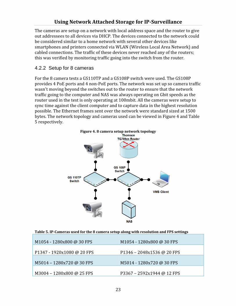
For the 8 camera tests a GS110TP and a GS108P switch were used. The GS108P provides 4 PoE ports and 4 non-PoE ports. The network was set up so camera traffic wasn't moving beyond the switches out to the router to ensure that the network traffic going to the computer and NAS was always operating on Gbit speeds as the router used in the test is only operating at 100mbit. All the cameras were setup to sync time against the client computer and to capture data in the highest resolution possible. The Ethernet frames sent over the network were standard sized at 1500 bytes. The network topology and cameras used can be viewed in Figure 4 and Table 5 respectively.
Figure 4. 8 camera setup network topology
Table 5. IP-Cameras used for the 8 camera setup along with resolution and FPS settings
M1054 - 1280x800 @ 30 FPS M1054 - 1280x800 @ 30 FPS
P1347 - 1920x1080 @ 20 FPS P1346 – 2048x1536 @ 20 FPS
M5014 – 1280x720 @ 30 FPS M5014 - 1280x720 @ 30 FPS
M3004 – 1280x800 @ 25 FPS P3367 – 2592x1944 @ 12 FPS

Using Network Attached Storage for IP-Surveillance
24
4.2.3 Hardware added and changes done for the 16 camera setup
The test setup for 16 cameras was quite similar, another 8 port GS110TP was added to the setup to provide enough ports for all the cameras as well as a Linksys E1500 Wifi router to replace the previously used router. A 24-port PoE switch would be preferable; this would limit the amount of switch transfers before the data reached its destination but that kind of equipment was not available at the time testing. Internet and Wireless connection was also disabled on the router during these tests. The network topology and cameras used can be viewed in Figure 4 and Table 6 respectively.
Figure 5. 16 camera setup network topology
Table 6. IP-Cameras used for the 16 camera setup along with resolution and FPS settings
M1054 - 1280x800 @ 30 FPS
M1054 - 1280x800 @ 30 FPS
M3204 – 1280x800 @ 30 FPS
M1144-L -1280x800 @ 30 FPS
P1347 - 1920x1080 @ 20 FPS
P1346 – 2048x1536 @ 20 FPS
M1013 - 1280x800 @ 30 FPS
M1013 - 1280x800 @ 30 FPS
M5014 - 1280x720 @ 30 FPS
M5014 - 1280x720 @ 30 FPS
P3343 - 800x600 @ 30 FPS
P3367 – 2592x1944 @ 12 FPS

Using Network Attached Storage for IP-Surveillance
25
M3004 – 1280x800 @ 25 FPS
M3004 – 1280x800 @ 25 FPS
M3014 – 1280x800 @ 25 FPS
P3367 – 2592x1944 @ 12 FPS
4.2.4 NAS configurations and SMB copy performance.
The three different NASes tested all belong in the SOHO segment; the systems tested are all QNAP 2-bay NAS-systems as indicated by the first number in the model name. The SMB copy tests were performed 5 times and then the average of those values were calculated. The specifications [59] and throughput can be viewed in table 7.
Table 7. The NAS systems tested and their specifications.
NAS QNAP TS-212 QNAP TS-219P II QNAP TS-269P
CPU Marvell 6281 1.2GHz
Marvell 6282 2.0 GHz
Intel® Atom 2.13GHz Dual-core Processor
Memory 256MB DDRII RAM
16 MB Flash memory
512MB DDRIII RAM 16 MB Flash Memory
1GB DDRIII RAM
512 MB Flash Memory
NIC 1000 mbit Ethernet (125MB/s)
1000 mbit Ethernet (125MB/s)
2x1000 mbit Ethernet (2x125MB/s)
Hard drive 2xST31000524AS(2x1TB)
2xWD1003FBYX (2x1TB)
2xWD1003FBYX (2x1TB)
Local File System ext4 ext4 ext4
Network File System
SMB/CIFS v1 SMB/CIFS v1 SMB/CIFS v1
Copy 5 GB videofile to NAS via SMB
34.7 MB/s 40.4 MB/s 84.5 MB /s
It is safe to say that the NAS copy performance could not in any way reach the limit of the network bandwidth even if a system bottleneck outside of the network exists because of the overhead produced by network protocols. Even when only using an ordinary Ethernet frame that does not impose an overhead used by other protocols the maximum rate is 97,6%, with TCP and UDP overhead at 94.9% and 95.7% respectively using Ipv4 (Internet Protocol version 4). This can be increased with

Using Network Attached Storage for IP-Surveillance
26
jumbo frames to a rate of 99.5% for Ethernet, 99.1% for TCP and 99.2% for UDP [60]. The RTP packets used for streaming the video also provide an extra header for the UDP datagram that carries the data, the size is variable depending on application and format being used.
4.2.5 Testing and collecting procedure
The tests were performed by logging all information with the nmon tool; the longer tests were performed over at least 24 hours and some tests spanning over several days with a red blob displayed on the client system monitor triggering motion detection on the cameras, this is also the type of tests done by the Axis QA department [25]. Each camera provides two streams one for motion detection data and one for the continuous recording. This is to provide as much stress as possible on the NAS during the tests. A playback of the recorded footage was also triggered at random intervals to observe the effect on the system. Several of these tests were done on each NAS system.
When collecting data over a day or several days the switches used with the nmon tool were the following depending on the amount of time for collecting data:
nmon –f –s300 –cXXXXXX
The nmon command with the –f switch states that the tool should start in data collection mode, the tool automatically names the file containing the collected data with the systems UNIX name. The –s describes how many seconds there should be in between data captures. The final –c command describes how many data captures should be executed before stopping the processes. So values were captured every five minutes for as long as the tests were run.
The shorter tests were performed with human movement in front of the cameras to trigger motion detection; these tests were also repeated several times to provide confirmation and validity of the tests. Another factor behind executing these tests several times is that the video format being used is a variable format and it is close to, if not impossible to achieve exactly the same bandwidth during separate test sessions.
The commands executed on these tests were:
nmon –ft –s1 –cXXX
This means data is collected every second for between 600-1200 seconds/10-20 minutes, but still with the one second capture interval. This was done to give a more accurate and detailed representation of the system and how it reacted to the video recording and playback on a second to second basis. The -t switch was also added to display processes executed on the system and what amount of CPU% the process in question uses.
Using Network Attached Storage for IP-Surveillance
27
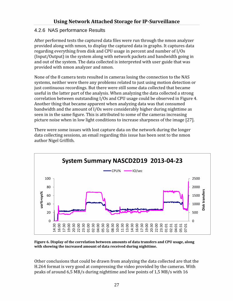
4.2.6 NAS performance Results
After performed tests the captured data files were run through the nmon analyzer provided along with nmon, to display the captured data in graphs. It captures data regarding everything from disk and CPU usage in percent and number of I/Os (Input/Output) in the system along with network packets and bandwidth going in and out of the system. The data collected is interpreted with user guide that was provided with nmon analyzer and nmon.
None of the 8 camera tests resulted in cameras losing the connection to the NAS systems, neither were there any problems related to just using motion detection or just continuous recordings. But there were still some data collected that became useful in the latter part of the analysis. When analyzing the data collected a strong correlation between outstanding I/Os and CPU usage could be observed in Figure 4. Another thing that became apparent when analyzing data was that consumed bandwidth and the amount of I/Os were considerably higher during nighttime as seen in in the same figure. This is attributed to some of the cameras increasing picture noise when in low light conditions to increase sharpness of the image [27].
There were some issues with lost capture data on the network during the longer data collecting sessions, an email regarding this issue has been sent to the nmon author Nigel Griffith.
Figure 6. Display of the correlation between amounts of data transfers and CPU usage, along with showing the increased amount of data received during nighttime.
Other conclusions that could be drawn from analyzing the data collected are that the H.264 format is very good at compressing the video provided by the cameras. With peaks of around 6,5 MB/s during nighttime and low points of 1,5 MB/s with 16
0
500
1000
1500
2000
2500
0
20
40
60
80
100
14
:30
16
:00
17
:30
19
:00
20
:30
22
:00
23
:30
01
:00
02
:30
04
:00
05
:30
07
:00
08
:30
10
:00
11
:30
13
:00
14
:30
16
:00
17
:30
19
:00
20
:30
22
:00
23
:30
01
:01
02
:31
04
:01
05
:31
07
:01
Dis
k tr
ansf
ers
usr
%+s
ys%
System Summary NASCD2D19 2013-04-23
CPU% IO/sec

Using Network Attached Storage for IP-Surveillance
28
-20
-10
0
10
20
08
:08
08
:08
08
:09
08
:09
08
:09
08
:09
08
:10
08
:10
08
:10
08
:11
08
:11
08
:11
08
:12
08
:12
08
:12
08
:12
08
:13
08
:13
08
:13
08
:14
08
:14
08
:14
08
:15
08
:15
08
:15
08
:15
08
:16
08
:16
08
:16
08
:17Th
ou
san
ds
of
byt
es
Network I/O NASCD2D19 (KB/s) - 2013-04-25
Total-Read Total-Write (-ve)
cameras running and triggering motion detection at regular intervals, this was not even close to hitting the average copy speed of 34,7 MB/s provided by the TS-212 NAS with the worst hardware.
The impact of the ability of the H.264 video compression format predicting movement is going to be performed as described earlier; it greatly limits the amount of data that every camera has to send even when motion detection is triggered on every camera equating to a total amount of 32 streams going into the NAS and with several going out as well considering the streams played back on the VMS client. None of these long run tests gave any impression of a problem with any of the tested NAS systems attributed with recording footage from 16 cameras using quotas for each camera with both continuous streaming and motion detection enabled with high frame rates and resolutions. Since no problems were encountered there was no need to troubleshoot and locate the offending component or components.
The shorter minute based stress tests with a large amount of movement in front of the cameras along with playing back recorded footage were performed on the TS-219PII. As seen in the below figure the bandwidth used was significantly higher compared to the previous tests. Reaching peaks of around 16 MB/s of received data and around 11 MB/s of sent data.
At the start of 8:11 on the Figure 7 graph when network traffic is peaking the CPU usage
is spiking at 100% (not displayed), despite this none of the cameras lost their connection
to the NAS and recordings were not interrupted.
The tests described earlier were also performed on the TS-212 NAS, during the tests three of the cameras lost their connection to the NAS and stops recording data, this is when receiving data in the 10 MB/s range. Another camera also starts losing its connection when a playback from one of the cameras started. As seen in the two following figures (Figure 8 and 9) during the tests we observed a high disk usage percentage of both hard drives along with high CPU usage during several occasions
Figure 7. Graph of one of the shorter tests with a high degree of human movement on the TS-219PII NAS

Using Network Attached Storage for IP-Surveillance
29
during the data collection. A high CPU wait time as can be observed in Figure 8. In Figure 9 both of the physical hard drives are presented during the same session. The disk busy % is reported by asking the disk if it is busy when data needs to be moved, performance problems generally occur when utilization exceeds 70%. This leads to longer wait times for I/O to complete and results in longer wait for processes to complete [61].
Figure 8. Graph of the TS-212 during a test performed with a high degree of human movement.
Figure 9. Graph of disk utilization of the two physical hard drives during the same test session.
The high utilization of the hard drives is most likely due to the constant random writes and reads because of the differing physical location of the data stored on the quotas on the hard drive. Despite only writing and reading quite an insignificant amount of data retrieved from the NIC as seen in figure 10 on the next page, there is also another factor explaining the extremely high disk usage which is brought up later in the chapter. Performance issues could also arise when using a highly fragmented drive [61]. Another reason that performance suffers is most likely because the quotas reserved for the cameras are always full to the extent that cleanup process sets in at 72% and new space constantly has to be allocated for the
0
20
40
60
80
100
15
:17
15
:17
15
:18
15
:18
15
:19
15
:19
15
:20
15
:20
15
:21
15
:21
15
:21
15
:22
15
:22
15
:23
15
:23
15
:24
15
:24
15
:24
15
:25
15
:26
15
:26
15
:27
15
:27
15
:28
15
:28
15
:29
15
:29
15
:29
15
:30
15
:30
CPU Total NASD0090F 2013-05-03
User% Sys% Wait%
020406080
100120
15
:17
15
:17
15
:18
15
:18
15
:19
15
:19
15
:20
15
:20
15
:21
15
:21
15
:21
15
:22
15
:22
15
:23
15
:23
15
:24
15
:24
15
:24
15
:25
15
:26
15
:26
15
:27
15
:27
15
:28
15
:28
15
:29
15
:29
15
:29
15
:30
15
:30
Disk %Busy NASD0090F 2013-05-03
sda sdb

Using Network Attached Storage for IP-Surveillance
30
data retrieved. The relation between performance and free disk space was discussed earlier when the hard drive tests were performed.
In Figure 10 the network I/O during the same session as the previous graphs can be seen, the numbers are not particularly high compared to what the system performed compared to the normal SMB transfer process and incoming data tops out about 10 MB/s with outgoing peaking at around 7MB/s.
Figure 10. Network during the same test session as referred to in the Figure 6 and 7.
The loss of connection to the tested system is indicated in the camera event and error log by the following lines:
<INFO > May 3 15:25:42 axis-00408cba12c9 disks[4195]: Disk available status changed for NetworkShare0. Status = 'Exiting' <INFO > May 3 15:25:42 axis-00408cba12c9 disks[4195]: Disk NetworkShare starting unmount w/ id 5 <INFO > May 3 15:25:42 axis-00408cba12c9 disks[4195]: Disk available status changed for NetworkShare. Status = 'Exiting' <INFO > May 3 15:25:45 axis-00408cba12c9 disks[4195]: Disk available status changed for NetworkShare0. Status = 'Unavailable'
CIFS VFS: Unexpected lookup error -112 CIFS VFS: No response for cmd 50 mid 64483 CIFS VFS: No response for cmd 50 mid 64484 CIFS VFS: Unexpected lookup error -112
Viewing other information gathered by the nmon collection there is also an indication that the problem is attributed to the SMB server where it at times uses up to 95% of the CPU, with the major CPU hog behind the SMB processes being the nmon software with tops of 6-7%.
The load average of the system was also extracted during the process when it was under as high load as possible. The value was extracted via SSH by issuing the cat
-10
-5
0
5
10
15
15
:17
15
:17
15
:18
15
:18
15
:19
15
:19
15
:20
15
:20
15
:21
15
:21
15
:21
15
:22
15
:22
15
:23
15
:23
15
:24
15
:24
15
:24
15
:25
15
:26
15
:26
15
:27
15
:27
15
:28
15
:28
15
:29
15
:29
15
:29
15
:30
15
:30Th
ou
san
ds
of
byt
es
Network I/O NASD0090F (KB/s) - 2013-05-03
Total-Read Total-Write (-ve)
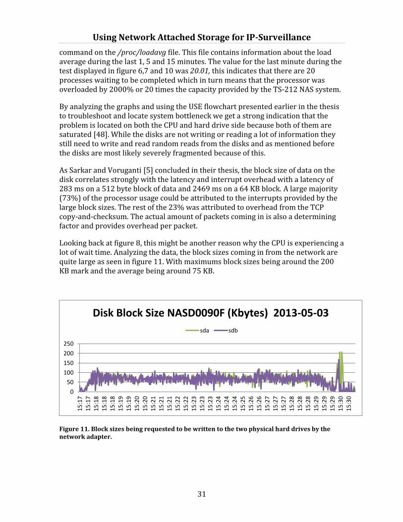
Using Network Attached Storage for IP-Surveillance
31
command on the /proc/loadavg file. This file contains information about the load average during the last 1, 5 and 15 minutes. The value for the last minute during the test displayed in figure 6,7 and 10 was 20.01, this indicates that there are 20 processes waiting to be completed which in turn means that the processor was overloaded by 2000% or 20 times the capacity provided by the TS-212 NAS system.
By analyzing the graphs and using the USE flowchart presented earlier in the thesis to troubleshoot and locate system bottleneck we get a strong indication that the problem is located on both the CPU and hard drive side because both of them are saturated [48]. While the disks are not writing or reading a lot of information they still need to write and read random reads from the disks and as mentioned before the disks are most likely severely fragmented because of this.
As Sarkar and Voruganti [5] concluded in their thesis, the block size of data on the disk correlates strongly with the latency and interrupt overhead with a latency of 283 ms on a 512 byte block of data and 2469 ms on a 64 KB block. A large majority (73%) of the processor usage could be attributed to the interrupts provided by the large block sizes. The rest of the 23% was attributed to overhead from the TCP copy-and-checksum. The actual amount of packets coming in is also a determining factor and provides overhead per packet.
Looking back at figure 8, this might be another reason why the CPU is experiencing a lot of wait time. Analyzing the data, the block sizes coming in from the network are quite large as seen in figure 11. With maximums block sizes being around the 200 KB mark and the average being around 75 KB.
Figure 11. Block sizes being requested to be written to the two physical hard drives by the network adapter.
0
50
100
150
200
250
15
:17
15
:17
15
:18
15
:18
15
:18
15
:19
15
:19
15
:20
15
:20
15
:21
15
:21
15
:21
15
:22
15
:22
15
:23
15
:23
15
:23
15
:24
15
:24
15
:24
15
:25
15
:26
15
:26
15
:27
15
:27
15
:27
15
:28
15
:28
15
:28
15
:29
15
:29
15
:29
15
:30
15
:30
Disk Block Size NASD0090F (Kbytes) 2013-05-03
sda sdb

Using Network Attached Storage for IP-Surveillance
32
Looking at the memory consumption on the NAS system losing connection to the cameras in figure 12, as soon as the cameras start recording the systems memory starts filling up to an extent where there isn’t much left. This is due to a feature in modern systems named DMA (Direct Memory Access), which is also supported by all of the systems tested [62, 63, 64]. Instead of letting the processor move the data through the storage and IP stack the system can instead put the data in the memory where the end device can fetch data directly.
It is hard to analyze if and when DMA sets in, but it should set in whenever the CPU is busy with other more important tasks or when it simply cannot handle the data transfer rate that needs to be serviced [65]. This would be a good indication why all the resources including the memory in the system are almost saturated with the exception of the network.
When having to use more temporary memory than available by the RAM, the system use something called a swap file. This swap file could be considered as a normal file residing on the hard drive/s and used when RAM is full to store temporary data that needs to be moved to another component in the system. This feature is a good way of utilizing hard drive capacity and performance when the RAM is full.
While this is an excellent way of storing data “on the move”, the swap file is limited by the poor performance (compared to the RAM) imposed by the mechanical hard drive as it is read and written from, the swap file causes the hard drive to perform these requests that would be unnecessary if the system had sufficient RAM.
Figure 12. Memory consumption during the test that failed
With a similar test on the 219PII NAS with similar peaks in traffic the same problem with low memory was encountered. Despite this the system never crashed but instead aborted the nmon monitoring tool and gave an error regarding memory allocation. This happens when a process with higher priority needs the memory and there is no space left.
0
20
40
60
80
100
15
:17
15
:17
15
:18
15
:18
15
:19
15
:19
15
:20
15
:20
15
:21
15
:21
15
:21
15
:22
15
:22
15
:23
15
:23
15
:24
15
:24
15
:24
15
:25
15
:26
15
:26
15
:27
15
:27
15
:28
15
:28
15
:29
15
:29
15
:29
15
:30
15
:30
Memory MB NASD0090F 2013-05-03 memfree
Using Network Attached Storage for IP-Surveillance
33
Another thing that needs to be taken into account is that the cameras seem to be losing connection when the NAS is exposed to sudden bursts of traffic. As seen in the previous graphs, the CPU load overall is very high over these periods of time. It is likely that the combination of data burst rate, amount of simultaneous connections and hard disk operations being requested both by writing and reading data directly to the disk, but mostly by utilizing the swap file to read and write temporary data. After a certain amount of time depending on data rate and state of the system there comes a point where the NAS-systems components simply doesn’t have the power to take care of all the data being sent from the connected cameras.
As can be concluded from the graphs everything in the system seems to be under heavy load but the deciding factor, and the bottleneck in the system that forced the cameras to stop recording are the hard drive disks. This is mainly because of the swap file being located on the hard drives used by the system as temporary memory when the RAM is full as well.
Using Network Attached Storage for IP-Surveillance
34
5 Improving performance
There are several ways of improving the performance for storing data over networks using the supplied configurations. The easiest solution would be to increase the RAM on the device (if possible) to limit the usage of the swap file. While the two following mentioned are not directly related to the bottleneck of the disks these suggestions are still valid for optimizing and better utilizing bandwidth and CPU usage.
Implementing SMB V2 on the cameras would limit the amount of overhead provided by SMB to negotiate by pipelining requests instead of having to send a response for every request. The problem with the limit of 64 kb block transfers in SMB v1 would likely also give a performance increase with the implementation of the latest version of the protocol. These suggestions would save some bandwidth especially in the negotiation phase as has been discussed in 3.2.1.
As recommended by Sarkar and Voruganti [14] enabling Jumbo Ethernet frames (Jumbo frames support 9000 bytes of data instead of the normal value of 1500 per frame) for sending and receiving to send data would limit the amount of interrupts required per data block and therefore lead to lower CPU consumption as well as provide a higher throughput on the network. This is of course dependent on that all network devices are enabled to carry and support jumbo frames. Another way to limit the amount of CPU usage required to transfer data would be to use a TCP/IP offload engine provided by some network cards. This makes the network adapter offload some of the TCP/IP overhead from the CPU. These types of NICs are not commonly available for SOHO grade NAS-systems at the time of writing.
As it was concluded that the storage media used was the bottleneck in the tested NAS-system there are different ways of bypassing this problem as well.
While this can’t be done with the 2-bay systems tested, expanding the RAID to include more disks and/or using other RAID levels for performance and redundancy like RAID 5 and RAID 1+0. Raid 5 would put more strain on the CPU by the parity calculations needed. Raid 1+0 would be ideal with performance boosts but has the same drawbacks as RAID 1, meaning it halves the disk space available by providing redundancy through mirroring disks [25, 26].
There is also the possibility of using SSD (Solid State Drive) as storage media in NAS. SSD drives are based on NAND-memory and provide a huge improvement in performance compared to normal mechanical hard drives. Using an SSD as a storage media would make the usage of a swap file much faster compared to mechanical disks. The drawbacks of using a SSD are that they only operate on a limit of the amount of rewrites before they stop operating and that they are considerably more expensive per amount of storage unit compared to their mechanical counterparts[31].
Using Network Attached Storage for IP-Surveillance
35
6 Testing Methods
The current tests performed by the Axis Quality Assurance using the red blob as described before does not seem to give the same bandwidth output from the cameras as human movement. As there is a huge discrepancy in bandwidth used when comparing the red blob tests triggering motion detection compared to the tests performed by triggering cameras with human movement. This is attributed to the prediction algorithms being employed to compress video and in this case H.264 discussed earlier in the thesis.
Simple bandwidth tests performed and presented in MB/s clearly are not suitable for measuring the amount of cameras suitable for a NAS. Looking at the NAS copy performance table and comparing it to what the NAS can handle in incoming video data there is around a 1/3 ratio in the NAS with the worst system specifications that dropped connection to the cameras.
Currently a tested method to benchmark NAS-systems being used to store and play back surveillance footage does not seem to exist. There are a few parameters that need to be decided before constructing these tests.
How should the tests be performed? Two possible solutions could be to either create an application or software that creates similar traffic to that of the cameras or create a feature in the cameras that emulates traffic to the NAS. Another option would be to set up the cameras in a real environment where there is lots of human movement and in that way provide a suitable amount of bandwidth to represent a normal camera installation. Both options could be used with the first one being used for stress testing and while the latter suggestion could be run over longer periods although the last suggestion is hard to repeat over and over again it would probably give the best indication on how an installation behaves at an end customer.
Measuring if the NAS passes the tests is another criteria, is it going to be as in the thesis presented, only when a camera loses its connection to the NAS and surveillance footage is lost or should the bar be set higher to check recorded footage for dropped frames or other characteristics.
The last part would be to decide what number of cameras, their settings and resolution a NAS should be able to record as this is quite an important factor regarding the amount of data that needs to be stored. Does it need to go into the extremes with full resolution and full frame rate settings for both continuous and motion detection recording as done in this thesis, or should the standard default settings be used for the tests?
Another option would be to test the hard disk drives individually apart from the NAS and see what differs in their performance. While the performance of the disks tested was only marginal; the difference of the amount of cache on the disk could have had an impact on disk performance under certain circumstances.

Using Network Attached Storage for IP-Surveillance
36
There are of course other options for testing NAS systems. These are ideas and suggestion based on the problems encountered during the testing process and derived from Rai Jains - Art of Computer System Performance Analysis Techniques for Experimental Design Measurements Simulation And Modeling [22].

Using Network Attached Storage for IP-Surveillance
37
7 Discussion and future work
With introduction of the new Google VP9 and h.265 video codecs around the corner the storage and network capabilities needed to store and send video will decrease even further compared current standards. In turn this will probably heighten the demand on cameras supporting high resolution video and along with this surveillance video so there is a possibility that bandwidth and data will even out with current needs because these two factors will cancel each other out.
Some of the hard disk drive manufacturers have just recently started releasing special mechanical drives designed specifically for surveillance storage. The emergence of cheaper SSDs is also a factor that can be included, and you can currently (June 2013) buy a 1 TB SSD for under 600$, but as discussed before these kinds of drives only have a limited amount of cycles they can be written before they stop working, the lifetime of these cheaper drives are even lower compared to the more expensive ones. Despite this SSD might be an option in the future when they get cheaper and get a longer lifespan.
As described in the beginning of this thesis there are a multitude of manufacturers for both IP-cameras and NAS-systems that work in different ways. While this thesis cannot begin to touch upon all these different factors, hopefully in the future it can be used as a basis when similar or adjacent research is performed.
Future work based on this thesis could be long-term impact and fragmentation of hard drives when using surveillance, or performance with SSDs.

Using Network Attached Storage for IP-Surveillance
38
Using Network Attached Storage for IP-Surveillance
39
8 Conclusion
This thesis discussed and analyzed how IP-surveillance works in conjunction with NAS as storage unit and the protocols and software associated with it. The NAS is an intricate device when many different variables to consider when purchasing one, especially with using it to store surveillance footage. The variety of systems is huge and variations in hardware, RAID levels, file systems and file sharing protocols are factors that play a role in the performance of the NAS. With the sometimes limited capabilities of collecting data provided by the NAS; external tools have to be used to be able to take a closer look into how it is processing data and what happens inside the system.
After analyzing the data it became apparent that there was not just one single performance problem with NAS systems being used together with IP-cameras but several ones. As indicated by the results from the data collected the storing of the video data captured by the cameras really puts a strain on the NAS and all the resources identified as important for general system performance are put on very high load with the most extreme being the CPU which is overloaded by over 20 times its capability. Despite this the overloaded CPU was not the component that was identified as the system bottleneck forcing the cameras to lose its connection to the NAS; but rather the hard disk drives that could not service all the requests that needed to be serviced for recording all data streams. Besides these two factors the memory starts to empty up just after recording begins, likely because of the DMA feature being used in modern systems to ease the load on the CPU when transferring data to the end components in the system. As the RAM fills up the system starts using the swap file stored on the hard drives as temporary memory. This result in an excessive amount of writes and reads from the hard drive that surpasses the capabilities of it.
A number of improvements were suggested to optimize and utilize the power offered by the tested systems. Some are easier and more practical than others to implement, like enabling jumbo frames. Some are harder, like implementing SMB v2 on the cameras and is most likely not worth the effort for the performance benefits. And then there are physically impossible ones that could solve the bottleneck issue encountered, like expanding the RAID. This is impossible because of the amount of hard drives supported in the tested systems.
Considering that the h.264 format is a variable format it is not very likely that the tests performed are representative for every situation possible in every environment. When testing NAS-systems in the future a few recommendations were suggested based on problems encountered during the performed tests and methods applied. These variables were used to create a guideline and a rough template on what should be considered in future tests.

References:
[1] Brownbridge, D. R., Marshall, L. F. and Randell, B. (1982), The newcastle connection or UNIXes of the world unite!. Softw: Pract. Exper., 12: 1147–1162.
[2] Garth A. Gibson and Rodney Van Meter. 2000. Network attached storage architecture. Commun. ACM 43, 11 (November 2000), 37-45
[3] Market for small IP camera installations expected to surge”, SecurityInfoWatch.com. [Online]. Available: http://www.securityinfowatch.com/article/10731727/market-for-small-ip-camera-installations-expected-to-surge. [Retrieved: 08-May-2013].
[4] Y. Deng, ”Deconstructing Network Attached Storage systems”, Journal of Network and Computer Applications, vol 32, num 5, pp 1064–1072, Sep 2009.
[5] P. Sarkar och K. Voruganti, ”IP Storage: The Challenge Ahead”, in NASA CONFERENCE PUBLICATION, 2002, pp 35–42.
[6] P. Sarkar, S. Uttamchandani, och K. Voruganti, ”Storage over IP: when does hardware support help?”, 2003.
[7] T. Bock, M. Cabot, F. Hady, och M. Shopsin, ”Measuring and Improving Single-User NAS Performance”.
[8] “Intransa Whitepaper – Video Surveillance and Eternal IP Storage Solutions” [Online] Available:http://www.intransa.com/pdfs/wp/Video-Storage-IP-SAN-vs-NAS-Whitepaper.pdf [Retrieved: 08-May-2013].
[9] ”Intransa Whitepaper – Video Surveillance and IP Storage” [Online] Available: http://www.intransa.com/pdfs/wp/Intransa-and-Genetec-Omnicast_wp.pdf [Retrieved: 08-May-2013]

[10] “Intransa Whitepaper –The Curious Case of Video Surveillance” [Online] Available: http://www.intransa.com/pdfs/wp/Intransa_Curious_Case_Video_Surv.pdf [Retrieved: 08-May-2013]
[11] ”Closed-circuit television”, Wikipedia, the free encyclopedia. 02-May-2013.
[12] Norris, C., McCahill, M. “On the Threshold to Urban Panopticon? Analysing the Employment of CCTV in European Cities and Assessing its social and Political Impacts – CCTV in Britain”. Centre for Criminology and Criminal Justce University of Hull, March 2002.
[13] Norris, C., McCahill, M. “On the Threshold to Urban Panopticon? Analysing the Employment of CCTV in European Cities and Assessing its social and Political Impacts – CCTV inLondon”. Centre for Criminology and Criminal Justce University of Hull, June 2002.
[14] "Television Rides Wires" B. Corporation, Popular Science. Bonnier Corporation, 1949.
[15] ”You’re being watched, New York!”, BBC, 11-Mar-2002.
[16] ”Surveillance video use skyrockets since 9/11 attacks”, http://www.patriotledger.com. [Online]. Available: http://www.patriotledger.com/news/x1431010560/Surveillance-video-use-skyrockets-since-9-11-attacks. [Retrieved: 08-May-2013].
[17] ”New Report Video Surveillance Market (2011 – 2016) by MarketsandMarkets”. [Online]. Available: http://www.prweb.com/releases/video-surveillance/market/prweb9609546.htm.[Retrieved: 08-May-2013].

[18] ”Market for small IP camera installations expected to surge”, SecurityInfoWatch.com. [Online]. Available: http://www.securityinfowatch.com/article/10731727/market-for-small-ip-camera-installations-expected-to-surge. [Retrieved: 08-May-2013].
[19] ”Report: Tipping point near for IP video equipment sales”, SecurityInfoWatch.com. [Online]. Available: http://www.securityinfowatch.com/news/10728047/report-tipping-point-near-for-ip-video-equipment-sales. [Retreived: 08-May-2013].
[20] “Network Attached Storage”. [Online]. Available: http://en.academic.ru/dic.nsf/enwiki/253303. [Retrieved: 08-May-2013].
[21] Berndtsson, M., Hansson, J., Lundell, B., Olsson, B. “Thesis Projects: A Guide for Students in Computer Science and Information Systems”. London: Springer-Verlag, 2008.
[22] Jain, R. “Art of Computer Systems Performance Analysis Techniques For Experimental Design Measurements Simulation And Modeling”. NY, Wiley & Sons. 1991.
[23] Gregg, B., 2012. Thinking Methodically about Performance. Queue 10, 40.
[24] ”DTrace”, Wikipedia, the free encyclopedia. 30-Apr-2013.
[25] Axis Q&A with Quality Assurance Dept. 2013-04-09
[26] R. Sohan och S. Hand, ”A user-level approach to network attached storage”, in Local Computer Networks, 2005. 30th Anniversary. The IEEE Conference on, 2005, pp 108–114.
[27] “Technical guide to network video” [Online] Available:http://www.axis.com/files/brochure/bc_techguide_47847_en_1305_lo.pdf [Retrieved: 01-May-2013]

[28] Ming-Jiang Yang; Jo Yew Tham; Dajun Wu; Kwong Huang Goh, "Cost effective IP camera for video surveillance," Industrial Electronics and Applications, 2009. ICIEA 2009. 4th IEEE Conference on , vol., no., pp.2432,2435, 25-27 May 2009
[29] ”Axis Communications - Network Camera Developer pages”. [Online]. Available:http://www.axis.com/techsup/cam_servers/dev/cam_http_api_index.php. [Retrieved: 01-May-2013].
30 ”Axis network cameras”. [Online]. Available: http://www.axis.com/files/brochure/bc_netcams_45129_en_1111_lo.pdf. [Retrieved: 01-May-2013].
[31] M, Myers CompTIA A+ Certification Exam Guide (Exams 220-801 & 220-802), Eight Edition, McGraw Hill, NY, 2012
[32] “Western Digital’s Advanced Format: The 4K Sector Transition Begins” by Ryan Smith Dec.18, 2009 [Online]. Available: http://www.anandtech.com/show/2888.[ Retrieved: 22-Maj-2013].
[33] Coughlin, Thomas; Grochowski, Edward (19 June 2012). "Years of Destiny: HDD Capital Spending and Technology Developments from 2012-2016". IEEE Santa Clara Valley Magnetics Society
[34] Interconnecting Cisco Network Devices, Part 1 (ICND1): CCNAExam 640-802 and ICND1 Exam 640-822 (2nd Edition), Stephen McQuerry pp.144-146, 238-242
[35] ”Introduction to PoE and the IEEE802.3af and 802.3at Standards” [Online] Available: http://www.ieee.li/pdf/viewgraphs/introduction_to_poe_ieee802.3af_802.3at.pdf [Retrieved: 16-April-2013
[36] ”[MS-CIFS]: Common Internet File System (CIFS) Protocol”. [Online]. Tillgänglig vid: http://msdn.microsoft.com/en-us/library/ee442092.aspx. [Retrieved: 05-Apr-2013].

[37] ”SMB2, a complete redesign of the main remote file protocol for Windows - Jose Barreto’s Blog - Site Home - TechNet Blogs”. [Online]. Available: http://blogs.technet.com/b/josebda/archive/2008/12/05/smb2-a-complete-redesign-of-the-main-remote-file-protocol-for-windows.aspx. [Retrieved: 08-Maj-2013].
[38] S. Chen och D. Towsley, ”A performance evaluation of RAID architectures”, IEEE Transactions on Computers, vol 45, num 10, pp 1116–1130, 1996.
[39] P. M. Chen, E. K. Lee, G. A. Gibson, R. H. Katz, och D. A. Patterson, ”RAID: High-performance, reliable secondary storage”, ACM Computing Surveys (CSUR), vol 26, num 2, ss 145–185, 1994.
[40] Jenwei Hsieh; Stanton, C.; Ali, R., "Performance evaluation of software RAID vs. hardware RAID for Parallel Virtual File System," Parallel and Distributed Systems, 2002. Proceedings. Ninth International Conference on, vol., no., pp.307,313, 17-20 Dec. 2002
[41] ”Axis Camera Companaion”. [Online]. Available: http://www.axis.com/files/datasheet/ds_acc_46565_en_1313_lo.pdf. [Retrieved: 01-May-2013].
[42] H. S. <[email protected]>, ”Real Time Streaming Protocol (RTSP)”. [Online]. Available: http://tools.ietf.org/html/rfc2326. [Retrieved: 02-May-2013].
[43] V. Jacobson, R. Frederick, S. Casner, och H. Schulzrinne, ”RTP: A Transport Protocol for Real-Time Applications”. [Online]. Available: http://tools.ietf.org/html/rfc3550. [Retrieved: 04-Maj-2013].
[44] ”VAPIX version 3 – RTSP API [Online]. Available: http://www.axis.com/files/manuals/RTSP_API_2_01.pdf. [Retrieved: 24-april-2013].
[45] Matroska Media Container - <http://matroska.org>

[46] Schwarz, H.; Marpe, D.; Wiegand, T., "Overview of the Scalable Video Coding Extension of the H.264/AVC Standard," Circuits and Systems for Video Technology, IEEE Transactions on , vol.17, no.9, pp.1103,1120, Sept. 2007
[47] Wiegand, T.; Sullivan, G.J.; Bjontegaard, G.; Luthra, A., "Overview of the H.264/AVC video coding standard," Circuits and Systems for Video Technology, IEEE Transactions on , vol.13, no.7, pp.560,576, July 2003
[48] F. Pereira och T. Ebrahimi, "Natural Video Coding" The MPEG-4 Book, 1st edition. New Jersey:Prentice Hall, 2002, pp.297-299.
[49] I. E. Richardson, "Introduction" The H.264 Advanced Video Compression Standard, 2nd edition. New York: Wiley, 2010. pp. 2-3.
[50] “List of video services using H.264/MPEG-4 AVC”, Wikipedia, the free encyclopedia 2013-04-19
[51] HD tune Pro 5.0 - <http://www.hdtune.com>
[52] ”WD RE4 Enterprise SATA Hard Drives datasheet” [Online] Available: http://www.wdc.com/wdproducts/library/SpecSheet/ENG/2879-701338.pdf.[Retrieved: 04-May-2013]
[53] “Seagate Barracuda 7200.12 specifications” [Online] Available: http://origin-www.seagate.com/internal-hard-drives/desktop-hard-drives/desktop-hdd/.[Retrieved: 04-May-2013]
[54] ”Seagate and Intel joint NCQ Whitepaper” [Online] Available: http://web.archive.org/web/20101218131508/http://seagate.com/content/pdf/whitepaper/D2c_tech_paper_intc-stx_sata_ncq.pdf.[Retrieved: 04-May-2013]
[55] Busybox - <http://www.busybox.net>
[56] Itsy Packet Manager (IPKG) - <http://www.nslu2-linux.org>
[57] Nigels Performance Monitor (nmon) - <http://nmon.sourceforge.net>
[58] “Axis Camera Companion – Best Practices – Network Attached Storage (NAS)”. [Online]. Available: http://www.axis.com/files/manuals/acc_NAS_best_practices_130312.pdf. [Retrieved: 01-May-2013]
[59] QNAP official website - <http://www.qnap.com>
[60] ”Protocol Overhead” by Phillip Dykstra July, 2011 [Online].Available: http://sd.wareonearth.com/~phil/net/overhead/.[Retrieved]: 02-May-2013]
[61] ”Troubleshooting IBM AIX servers, IBM” [Online].Available: http://publib.boulder.ibm.com/infocenter/pseries/v5r3/index.jsp [Retrieved: 05-May-2013]
[62] ”Marvell 88F6282 SoC Overview” [Online].Available: https://origin-www.marvell.com/embedded-processors/kirkwood/assets/88f6282-3_pb.pdf. [Retrieved: 05-May-2013]
[63] “Marvell 88F6281 SoC with Sheeva Technology Overview” [Online].Available: https://origin-www.marvell.com/embedded-processors/kirkwood/assets/88F6281-004_ver1.pdf. [Retrieved: 05-May-2013]
[64] “Intel Atom Processor D2700 Specifications” [Online].Available: http://ark.intel.com/products/59683. [Retrieved: 05-May-2013]
[65] Corbet, J., Rubini, A., Kroah-Hartman, G., "Memory mapping and DMA” Linux Device Drivers, 3rd edition. California: O’reilly media inc, 2005. pp. 441-451.

HÖGSKOLAN I HALMSTAD • Box 823 • 301 18 Halmstad • www.hh.se

HALMSTAD UNIVERSITY • PO Box 823 • SE-301 18 Halmstad, Sweden • www.hh.se