karelia university of applied science degree program …
TRANSCRIPT
KARELIA UNIVERSITY OF APPLIED SCIENCE Degree Program in Mechanical Engineering
Moharram Shoja Jamalabad
GENMARK ROBOT AUTOMATION
Thesis June 2020
THESIS June 2020 Degree Programme in Mechanical Engineering Tikkarinne 9 80220 JOENSUU + 385 13 260 600
Author Moharram Shoja Jamalabad
Title Genmark Robot Automation Commissioned by Karelia University of Applied Science
Abstract Integrated circuits are produced from wafers of semiconductor material. The industry requires precise, clean fabrication process. In any nanoscience industry, most of the fabrication process is performed in a cleanroom environment. Handling of the substrates and material is critical and demanding high speed, precise and repeatable robots. Positioning of the substrates without damaging needs precision and accurate teaching of the robot. Various types of wafer handling devices are known for transporting the wafers to and from the cassette and among processing stations. Genmark robots are multi-axis, high precision and high-speed robots, featuring a gimbal positioning platform control. These robots may operate both in cylindrical and cartesian coordinates, on a plane and in space. In this thesis, the detail of the teaching of the Genmark robot has been discussed.
Language English
Pages 40
Appendices 0
Appendix pages 0
Pages of Appendices 0
Keywords GenMark, Gencobot, GenMark Comments, GenMark training, wafer handling, End effectors
OPINNÄYTETYÖ kesäkuu 2020 Insinööri, Konetekniikka
Tikkarinne 9 80220 JOENSUU + 385 13 260 600
Tekijä(t) Moharram Shoja Jamalabad
Nimeke
Genmark Robot Automation
Toimeksiantaja Karelia-Ammattikorkeakoulu
Tiivistelmä Integroitujen piirien valmistuksessa käytetään puolijohdemateriaalista valmistettuja kiekkoja. Tämänkaltainen teollisuus vaatii tarkan ja puhtaan valmistusprosessin. Millä tahansa nanotieteiden alalla suurin osa valmistusprosessista suoritetaan puhdastiloissa. Alustojen ja materiaalien käsittely on kriittistä ja vaatii nopeaa, tarkkaan liikkeensä toistavaa robottia. Kiekkojen sijoittaminen niitä vahingoittamatta vaatii robotin erittäin tarkkaa opetusta. Erilaisia käsittelylaitteita joilla kiekko voidaan kuljettaa kasetista käsittelyasemaan ja käsittelyasemien välillä, on useita. Näistä käsittelylaitteista Genmark-robotit ovat moniakselisia, tarkkoja ja erittäin nopeita. Nämä robotit on varustettu nivelen asemonnin ohjauksella, ja voivat toimia sekä lieriömäisissä, että suorakulmaisissa koordinaateissa, tasossa ja avaruudessa. Tässä opinnäytetyössä on käsitelty Genmark-robotin opetuksen yksityiskohtia.
Kieli Englanti
Sivuja 40
Liitteet
Liitesivumäärä
Asiasanat GenMark, Gencobot, GenMark Comments, GenMark training, wafer handling, End effectors
CONTENTS 1 INTRODUCTION .......................................................................................... 5 2 CLEANROOM ENVIRONMENT ................................................................... 6 2.1 Cleanroom classification ................................................................... 7 2.2 Handling in cleanroom ...................................................................... 9 3 ROBOT HANDLING SYSTEM DESCRIPTION ............................................. 9 3.1 General safety precautions ............................................................. 11 4 INSTALLING ROBOT ................................................................................. 13 4.1 Communication with controller ........................................................ 14 5 GENERAL DESCRIPTION OF ROBOT ...................................................... 15 5.1 GenMark robot design and kinematics ............................................ 15 5.2 Motion axis ...................................................................................... 16 5.3 Robot Home position ....................................................................... 17 6 MOTION COMMANDS ............................................................................... 18 6.1 Moving along a given motion axis or axes ...................................... 18 6.2 Move relative action ........................................................................ 19 6.3 Move to point action ........................................................................ 20 6.4 Movement over a straight line ......................................................... 20 6.5 Tilting of end effector ....................................................................... 22 6.6 Tilt around the default Axis .............................................................. 22 6.7 Tilt around X Axis ............................................................................ 23 7 MATERIAL DETECTION IN GENMARK ..................................................... 24 7.1 Vacuum sensor calibration .............................................................. 25 7.2 Checking vacuum by genmark commands ..................................... 25 8 SUMMARY OF ROBOT COMMANDS ........................................................ 27 9 TEACHING STATION AND POSITION FOR ROBOT ................................ 28 9.1 Station name ................................................................................... 28 9.2 Teaching station to robot ................................................................. 29 9.3. Stroke and coordinate ..................................................................... 32 10 ROBOT END EFFECTORS ........................................................................ 33 10.1 Edge handling end effector .............................................................. 33 10.2 Center handling end effector ............................................................ 34 11 END EFFECTOR REPLACEMENT ............................................................ 35 12 PREVENTIVE MAINTENANCE FOR ROBOT ............................................ 38 13 CONCLUSION ........................................................................................... 39 REFERENCES ................................................................................................... 40
5
1 INTRODUCTION
Robots are machines designed to perform a task by doing a complex series of
functions automatically. They are used in variety of applications, i.e.,
manufacturing, healthcare, and even space for automation of most tedious, dull,
and unsafe tasks. Industrial robots are used for welding, material handling,
painting, packaging and many other tasks. Robots can be programmed to work
24 hours per day. Robots can be used for improving the production throughput
and quality which are two winning parameters in the industry [1].
Most of industrial robots fall into the manipulator category. Robot manipulator is
an open or closed kinematic chain of rigid links interconnected by movable joints.
Some robots are repeating a task over and over but there are robots that are
equipped with sensors, machine vision and programmed to identify the processor
task that needs to be performed. While selecting a robot for a process, several
parameters such as speed, degree of freedom, repeatability, accuracy,
performance, and end effectors requires the special attention [2].
In this thesis, the main focus is on wafer handling and robot teaching methods for
different stations. Many brands such as Kawasaki, Fanuc, Yaskawa, Genmark
and ABB are supplying robots for handling material. This thesis gives a special
outlook and deferent point of view on genmark robot handling, its building blocks
and interaction in large area nanofabrication process. Genmark robot’s
automation system is commonly used in silicon and semiconductor
nanofabrication industry. They are primarily designed for integration and handling
of the glass and silicon wafers. They perform pick and place operations in
complex environments such as cleanrooms.
Robot automation increases the throughput and precision and it decreases the
human originated defects by decreasing manual interference in the fabrication
process.
6
Therefore, precise robot teaching is a necessary task. Accurate teaching of the
robot can lead to high quality handling of the products with increased speed,
decreased yield loss and improved throughput. The motivation of this thesis work
is providing the detail of GenMark robot training for a precise and flawless
operation in the process.
2 CLEANROOM ENVIRONMENT
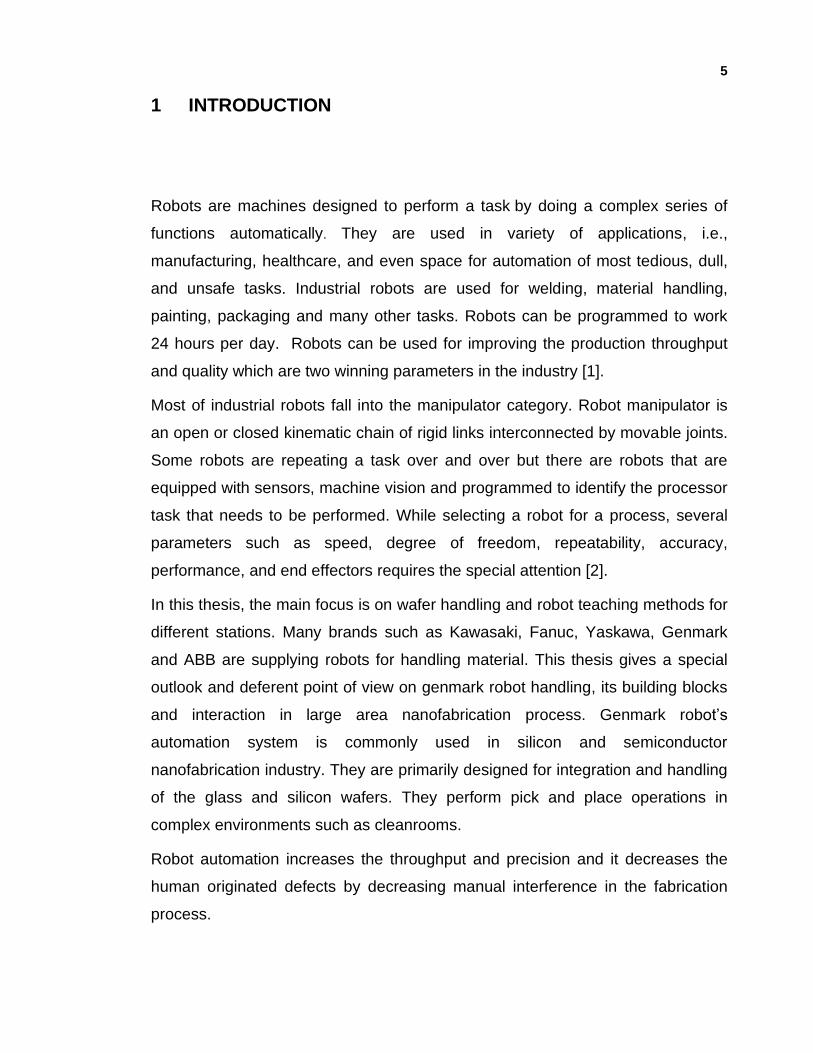
Semiconductor applications demand high-precision automation and reliable,
predictable performance for wafer transport within clean and controlled
environments called cleanroom (figure 1).
Cleanroom is a room in which the concentration of airborne particles, aerosols,
and chemical vapors is controlled, and it is constructed and used in a manner to
minimize the introduction, generation, and retention of particles inside. In the
cleanroom other relevant parameters, i.e., temperature, humidity, and pressure
and static energy are controlled, as necessary.
a) b)
Figure 1: a) A process silicon wafer by nanofabrication, b) working environment in silicon industry. (Source: angstromtechnology.com/difference-controlled-environment-cleanroom 2019).
7
A cleanroom is an environment that is following the standard rules to have a
controlled level of contamination which is defined by the number of particles per
cubic meter and a specified particle size. The number of particles in the air in a
typical environment is about 35 million/m2 with the particles that are larger than
0.5 µm in size. In the cleanroom the particles that are in the size of 0.3 µm and
larger are filtered by high efficiency particulate air (HEPA) filters [3]. Also, for the
cleanrooms that are used for nanofabrication, certain temperature and humidity is
needed. Therefore, usually in the cleanrooms there are tools to monitor particle
count, environment temperature and humidity precisely.
2.1 Cleanroom classifications
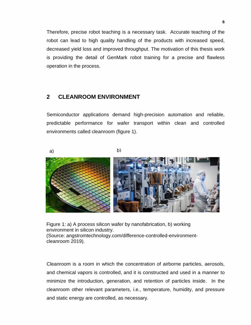
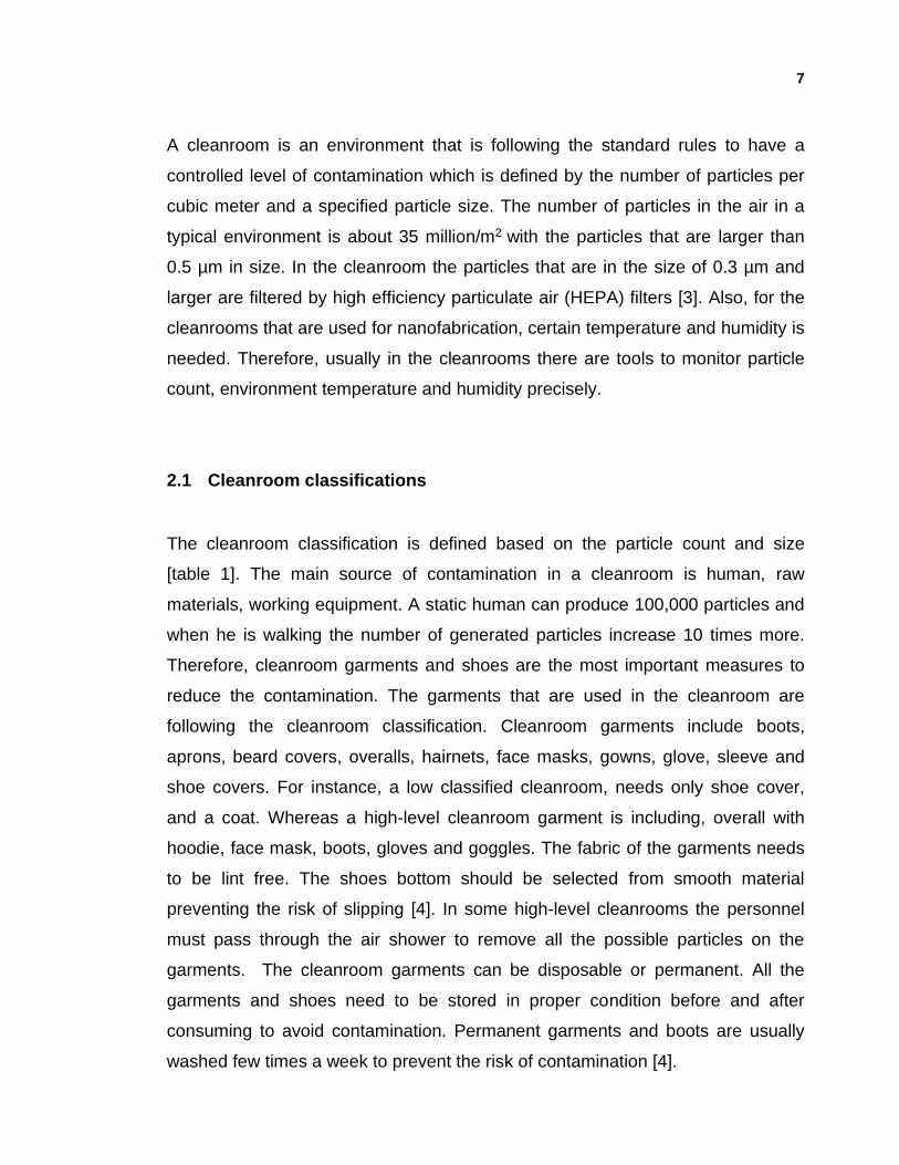
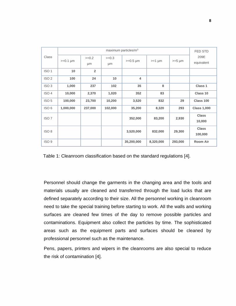
The cleanroom classification is defined based on the particle count and size
[table 1]. The main source of contamination in a cleanroom is human, raw
materials, working equipment. A static human can produce 100,000 particles and
when he is walking the number of generated particles increase 10 times more.
Therefore, cleanroom garments and shoes are the most important measures to
reduce the contamination. The garments that are used in the cleanroom are
following the cleanroom classification. Cleanroom garments include boots,
aprons, beard covers, overalls, hairnets, face masks, gowns, glove, sleeve and
shoe covers. For instance, a low classified cleanroom, needs only shoe cover,
and a coat. Whereas a high-level cleanroom garment is including, overall with
hoodie, face mask, boots, gloves and goggles. The fabric of the garments needs
to be lint free. The shoes bottom should be selected from smooth material
preventing the risk of slipping [4]. In some high-level cleanrooms the personnel
must pass through the air shower to remove all the possible particles on the
garments. The cleanroom garments can be disposable or permanent. All the
garments and shoes need to be stored in proper condition before and after
consuming to avoid contamination. Permanent garments and boots are usually
washed few times a week to prevent the risk of contamination [4].
8
Class
maximum particles/m3 FED STD
209E
equivalent >=0.1 µm
>=0.2
µm
>=0.3
µm >=0.5 µm >=1 µm >=5 µm
ISO 1 10 2
ISO 2 100 24 10 4
ISO 3 1,000 237 102 35 8 Class 1
ISO 4 10,000 2,370 1,020 352 83 Class 10
ISO 5 100,000 23,700 10,200 3,520 832 29 Class 100
ISO 6 1,000,000 237,000 102,000 35,200 8,320 293 Class 1,000
ISO 7 352,000 83,200 2,930 Class
10,000
ISO 8 3,520,000 832,000 29,300 Class
100,000
ISO 9 35,200,000 8,320,000 293,000 Room Air
Personnel should change the garments in the changing area and the tools and
materials usually are cleaned and transferred through the load lucks that are
defined separately according to their size. All the personnel working in cleanroom
need to take the special training before starting to work. All the walls and working
surfaces are cleaned few times of the day to remove possible particles and
contaminations. Equipment also collect the particles by time. The sophisticated
areas such as the equipment parts and surfaces should be cleaned by
professional personnel such as the maintenance.
Pens, papers, printers and wipers in the cleanrooms are also special to reduce
the risk of contamination [4].
Table 1: Cleanroom classification based on the standard regulations [4].
9
2.2 Handling in cleanroom
Each cleanroom has its no-touch rules for handling the materials. For instance, in
semiconductor industry, silicon wafers cannot be handled manually. Usually
robots are the best options for handling regarding minimizing the handling
defects, particles, precision and increasing the throughput. Cleanroom robots are
used predominantly in machine loading, unloading, and parts transfer in the
semiconductor industry. The robot arms developed for cleanroom applications
are usually designed with ease of use in mind, including through-arm cable and
tube technology, standard interfacing with peripheral equipment, and a full
automatic wafer handling teaching option for the semiconductor series.
Cleanroom robots boast industry leading speed, repeatability, and reliability
which are crucial elements in industries focused around increasing demand. [4]
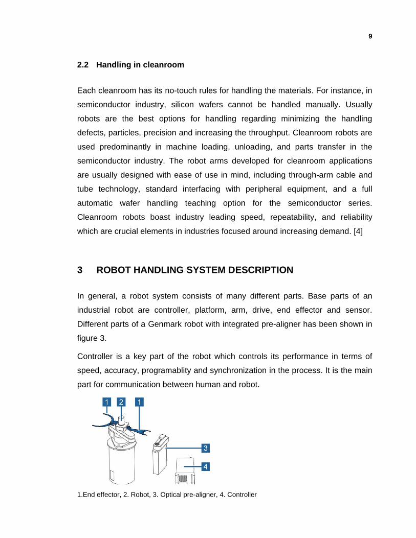
3 ROBOT HANDLING SYSTEM DESCRIPTION
In general, a robot system consists of many different parts. Base parts of an
industrial robot are controller, platform, arm, drive, end effector and sensor.
Different parts of a Genmark robot with integrated pre-aligner has been shown in
figure 3.
Controller is a key part of the robot which controls its performance in terms of
speed, accuracy, programablity and synchronization in the process. It is the main
part for communication between human and robot.
1.End effector, 2. Robot, 3. Optical pre-aligner, 4. Controller
10
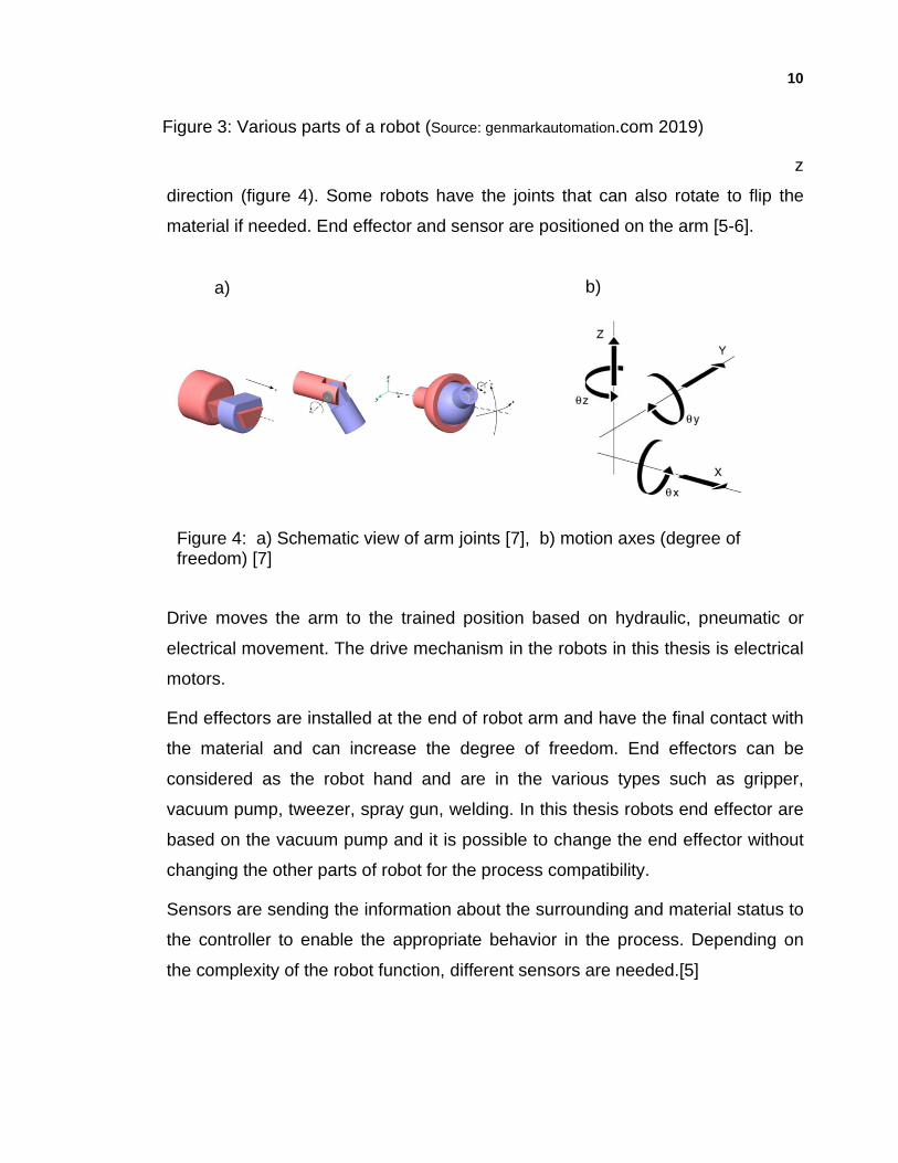
Robot arm is designed in a way that gives the freedom of movement in x, y and z
direction (figure 4). Some robots have the joints that can also rotate to flip the
material if needed. End effector and sensor are positioned on the arm [5-6].
Drive moves the arm to the trained position based on hydraulic, pneumatic or
electrical movement. The drive mechanism in the robots in this thesis is electrical
motors.
End effectors are installed at the end of robot arm and have the final contact with
the material and can increase the degree of freedom. End effectors can be
considered as the robot hand and are in the various types such as gripper,
vacuum pump, tweezer, spray gun, welding. In this thesis robots end effector are
based on the vacuum pump and it is possible to change the end effector without
changing the other parts of robot for the process compatibility.
Sensors are sending the information about the surrounding and material status to
the controller to enable the appropriate behavior in the process. Depending on
the complexity of the robot function, different sensors are needed.[5]
a) b)
Figure 4: a) Schematic view of arm joints [7], b) motion axes (degree of freedom) [7]
Figure 3: Various parts of a robot (Source: genmarkautomation.com 2019)
11
3.1 General safety precautions
Every equipment needs to be used with caution and paying attention to the safety
instructions. One must read all safety precautions before turning controller ON.
Following the guidelines are important during handling and operating the robot
system to prevent any personal injuries. If safety precautions are not followed
various dangerous situations which are mentioned in below can occur [6]:
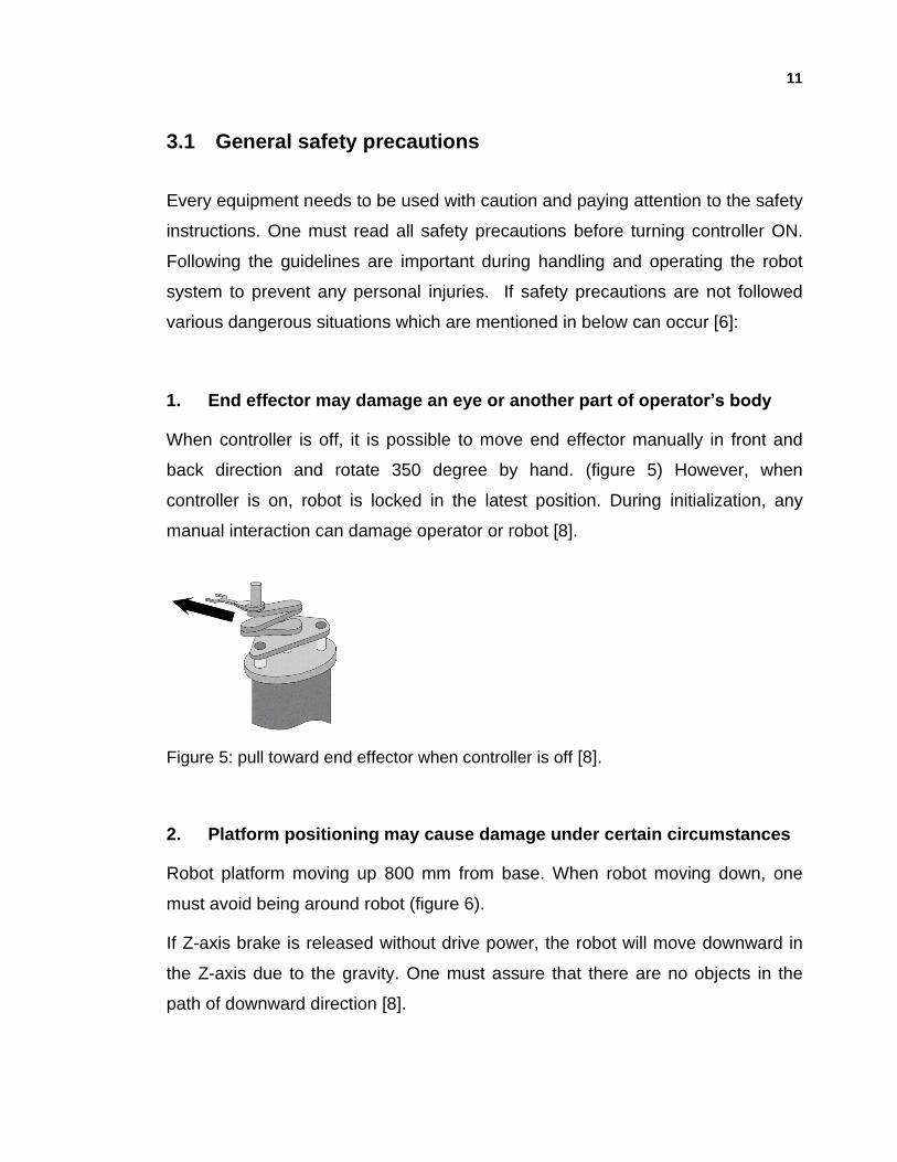
1. End effector may damage an eye or another part of operator’s body
When controller is off, it is possible to move end effector manually in front and
back direction and rotate 350 degree by hand. (figure 5) However, when
controller is on, robot is locked in the latest position. During initialization, any
manual interaction can damage operator or robot [8].
Figure 5: pull toward end effector when controller is off [8].
2. Platform positioning may cause damage under certain circumstances
Robot platform moving up 800 mm from base. When robot moving down, one
must avoid being around robot (figure 6).
If Z-axis brake is released without drive power, the robot will move downward in
the Z-axis due to the gravity. One must assure that there are no objects in the
path of downward direction [8].
12
Figure 6: Z- axis movement [8].
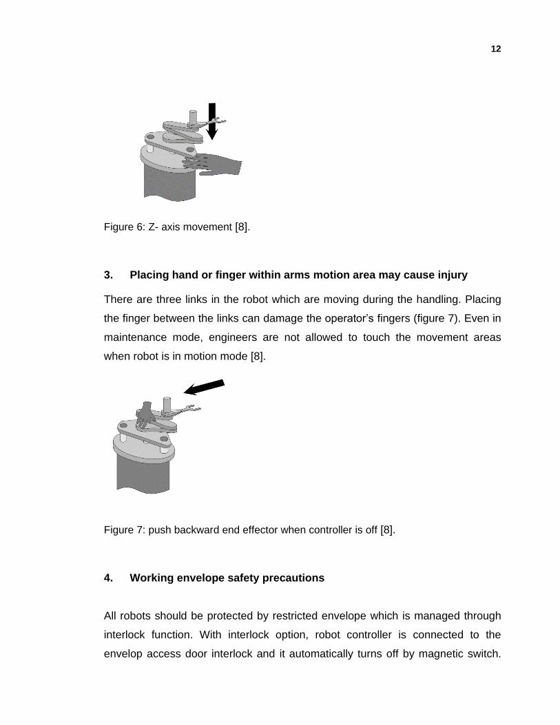
3. Placing hand or finger within arms motion area may cause injury
There are three links in the robot which are moving during the handling. Placing
the finger between the links can damage the operator’s fingers (figure 7). Even in
maintenance mode, engineers are not allowed to touch the movement areas
when robot is in motion mode [8].
Figure 7: push backward end effector when controller is off [8].
4. Working envelope safety precautions
All robots should be protected by restricted envelope which is managed through
interlock function. With interlock option, robot controller is connected to the
envelop access door interlock and it automatically turns off by magnetic switch.
13
Robot will be disabled when the door is open. It will stay disabled still after
closing the door and until reset bottom is pressed.
4 INSTALLING THE ROBOT
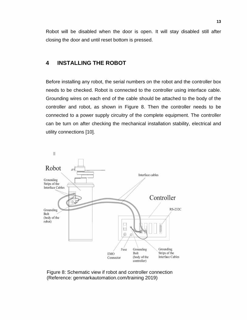
Before installing any robot, the serial numbers on the robot and the controller box
needs to be checked. Robot is connected to the controller using interface cable.
Grounding wires on each end of the cable should be attached to the body of the
controller and robot, as shown in Figure 8. Then the controller needs to be
connected to a power supply circuitry of the complete equipment. The controller
can be turn on after checking the mechanical installation stability, electrical and
utility connections [10].
Figure 8: Schematic view if robot and controller connection (Reference: genmarkautomation.com/training 2019)
14
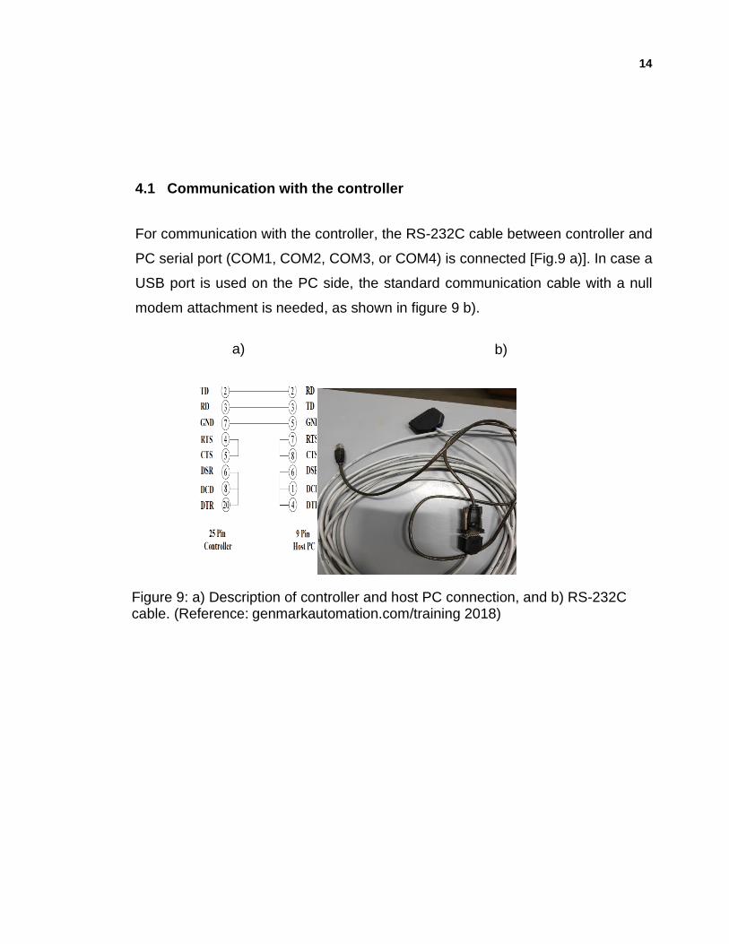
4.1 Communication with the controller
For communication with the controller, the RS-232C cable between controller and
PC serial port (COM1, COM2, COM3, or COM4) is connected [Fig.9 a)]. In case a
USB port is used on the PC side, the standard communication cable with a null
modem attachment is needed, as shown in figure 9 b).
Figure 9: a) Description of controller and host PC connection, and b) RS-232C cable. (Reference: genmarkautomation.com/training 2018)
a) b)
15
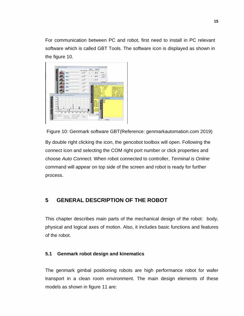
For communication between PC and robot, first need to install in PC relevant
software which is called GBT Tools. The software icon is displayed as shown in
the figure 10.
Figure 10: Genmark software GBT(Reference: genmarkautomation.com 2019)
By double right clicking the icon, the gencobot toolbox will open. Following the
connect icon and selecting the COM right port number or click properties and
choose Auto Connect. When robot connected to controller, Terminal is Online
command will appear on top side of the screen and robot is ready for further
process.
5 GENERAL DESCRIPTION OF THE ROBOT
This chapter describes main parts of the mechanical design of the robot: body,
physical and logical axes of motion. Also, it includes basic functions and features
of the robot.
5.1 Genmark robot design and kinematics
The genmark gimbal positioning robots are high performance robot for wafer
transport in a clean room environment. The main design elements of these
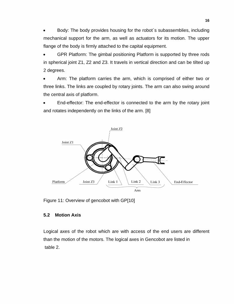
models as shown in figure 11 are:
16
• Body: The body provides housing for the robot`s subassemblies, including
mechanical support for the arm, as well as actuators for its motion. The upper
flange of the body is firmly attached to the capital equipment.
• GPR Platform: The gimbal positioning Platform is supported by three rods
in spherical joint Z1, Z2 and Z3. It travels in vertical direction and can be tilted up
2 degrees.
• Arm: The platform carries the arm, which is comprised of either two or
three links. The links are coupled by rotary joints. The arm can also swing around
the central axis of platform.
• End-effector: The end-effector is connected to the arm by the rotary joint
and rotates independently on the links of the arm. [8]
Figure 11: Overview of gencobot with GP[10]
5.2 Motion Axis
Logical axes of the robot which are with access of the end users are different
than the motion of the motors. The logical axes in Gencobot are listed in
table 2.
17
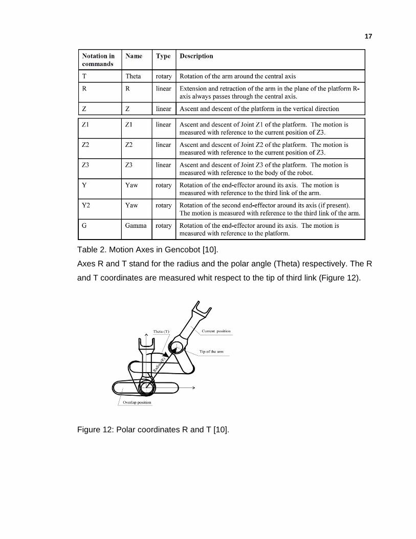
Table 2. Motion Axes in Gencobot [10].
Axes R and T stand for the radius and the polar angle (Theta) respectively. The R
and T coordinates are measured whit respect to the tip of third link (Figure 12).
Figure 12: Polar coordinates R and T [10].
18
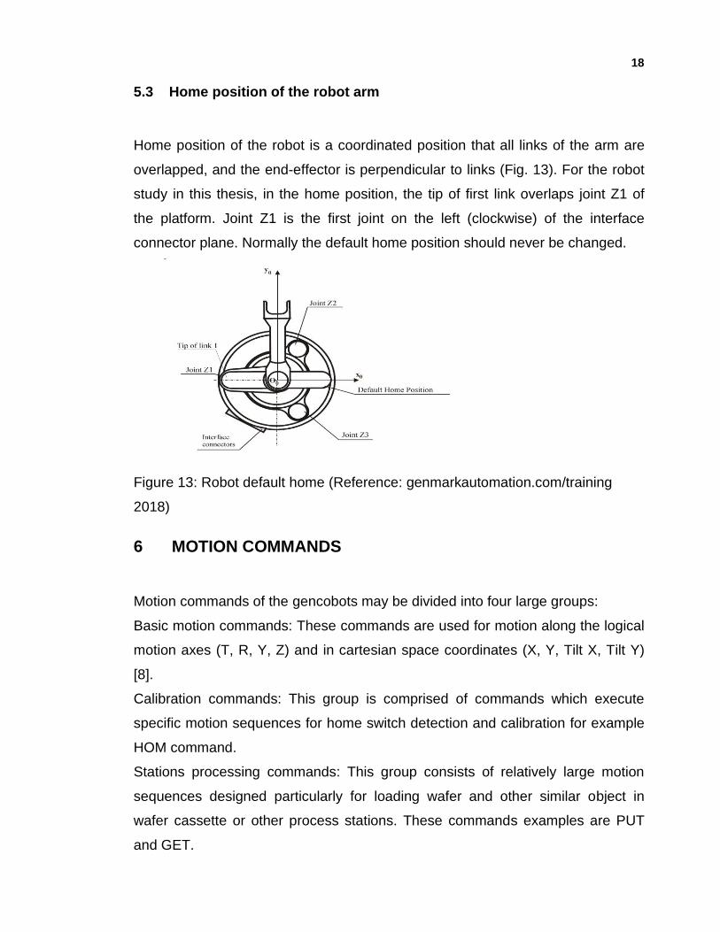
5.3 Home position of the robot arm
Home position of the robot is a coordinated position that all links of the arm are
overlapped, and the end-effector is perpendicular to links (Fig. 13). For the robot
study in this thesis, in the home position, the tip of first link overlaps joint Z1 of
the platform. Joint Z1 is the first joint on the left (clockwise) of the interface
connector plane. Normally the default home position should never be changed.
Figure 13: Robot default home (Reference: genmarkautomation.com/training
2018)
6 MOTION COMMANDS
Motion commands of the gencobots may be divided into four large groups:
Basic motion commands: These commands are used for motion along the logical
motion axes (T, R, Y, Z) and in cartesian space coordinates (X, Y, Tilt X, Tilt Y)
[8].
Calibration commands: This group is comprised of commands which execute
specific motion sequences for home switch detection and calibration for example
HOM command.
Stations processing commands: This group consists of relatively large motion
sequences designed particularly for loading wafer and other similar object in
wafer cassette or other process stations. These commands examples are PUT
and GET.
19
Special operation commands: These include special motion sequences specific
for scanning and prealigning operations. Example of such commands is SCN [9].
6.1 Move along a given motion axis or axes
Move along the axis, moves the certain axis from the current position to a new
position. For the execution of the MVA command the axis and the value of
movement is applied. The logical axis can be T, R, Y, Z. The movement in the
robots of this study are based on the step motor movement. Therefore, the
movement value is in the steps which leads in the movement in the millimeter.
The step size should be known prior to the command [9].
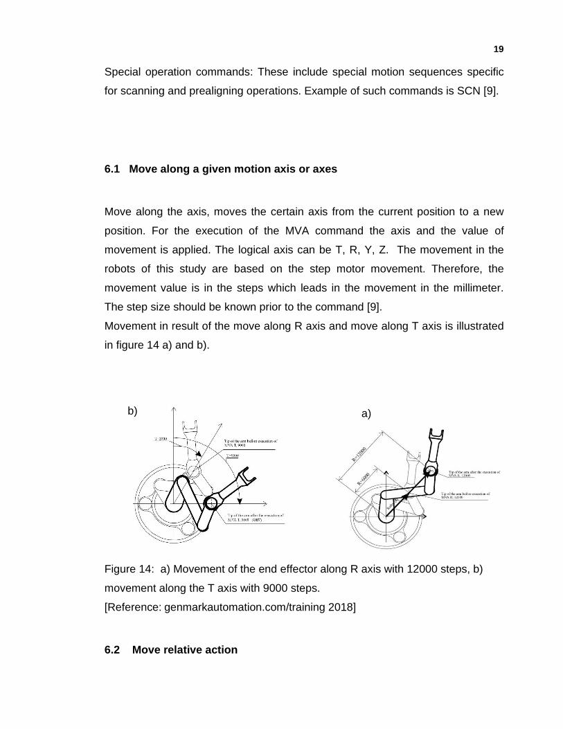
Movement in result of the move along R axis and move along T axis is illustrated
in figure 14 a) and b).
Figure 14: a) Movement of the end effector along R axis with 12000 steps, b)
movement along the T axis with 9000 steps.
[Reference: genmarkautomation.com/training 2018]
6.2 Move relative action
a)
b)
20
The move relative moves specified logical motion axis from its current position to
a new position by the specified value parameter and MVA command with the axis
and value can be used for this movement.
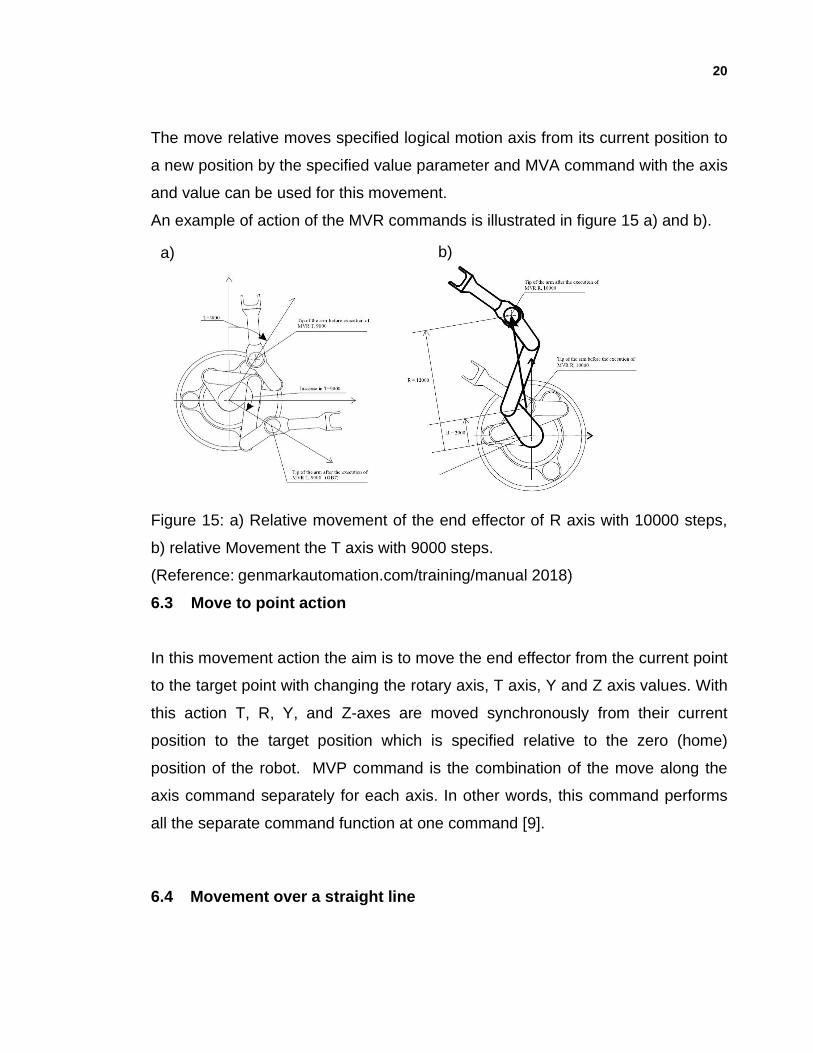
An example of action of the MVR commands is illustrated in figure 15 a) and b).
Figure 15: a) Relative movement of the end effector of R axis with 10000 steps,
b) relative Movement the T axis with 9000 steps.
(Reference: genmarkautomation.com/training/manual 2018)
6.3 Move to point action
In this movement action the aim is to move the end effector from the current point
to the target point with changing the rotary axis, T axis, Y and Z axis values. With
this action T, R, Y, and Z-axes are moved synchronously from their current
position to the target position which is specified relative to the zero (home)
position of the robot. MVP command is the combination of the move along the
axis command separately for each axis. In other words, this command performs
all the separate command function at one command [9].
6.4 Movement over a straight line
b)
a)
21
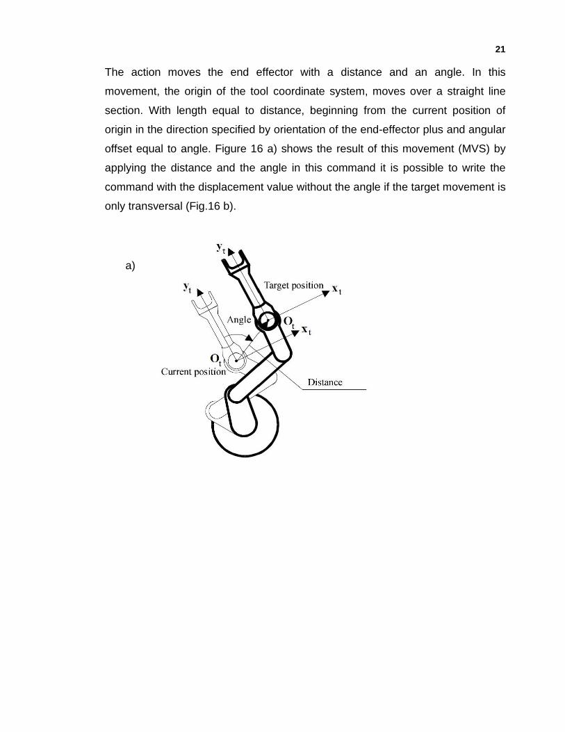
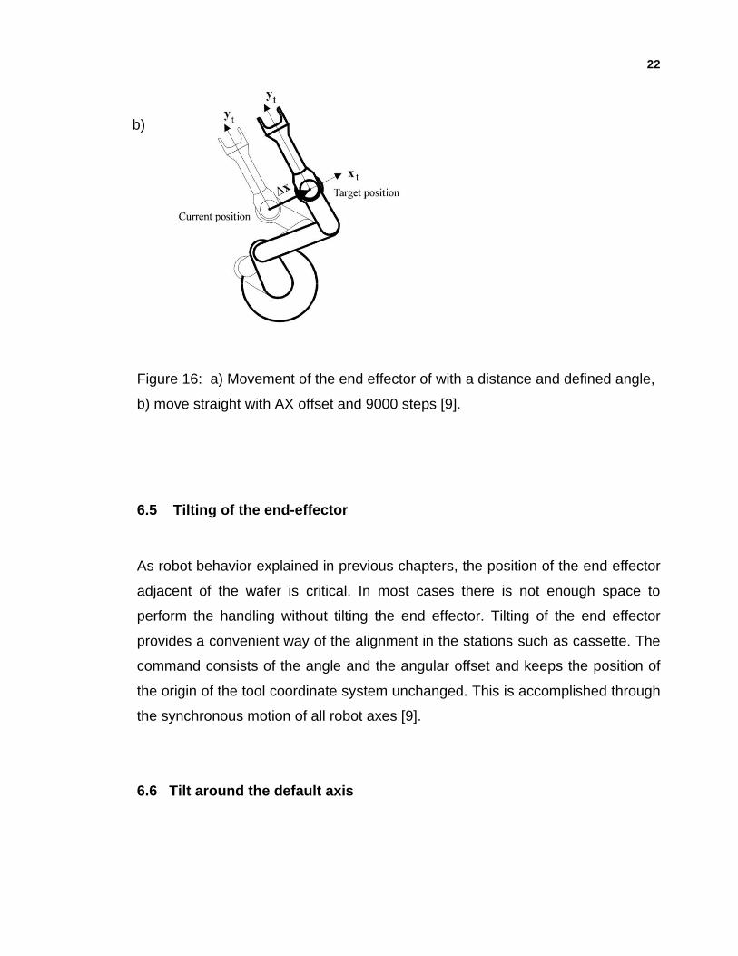
The action moves the end effector with a distance and an angle. In this
movement, the origin of the tool coordinate system, moves over a straight line
section. With length equal to distance, beginning from the current position of
origin in the direction specified by orientation of the end-effector plus and angular
offset equal to angle. Figure 16 a) shows the result of this movement (MVS) by
applying the distance and the angle in this command it is possible to write the
command with the displacement value without the angle if the target movement is
only transversal (Fig.16 b).
a)
22
Figure 16: a) Movement of the end effector of with a distance and defined angle,
b) move straight with AX offset and 9000 steps [9].
6.5 Tilting of the end-effector
As robot behavior explained in previous chapters, the position of the end effector
adjacent of the wafer is critical. In most cases there is not enough space to
perform the handling without tilting the end effector. Tilting of the end effector
provides a convenient way of the alignment in the stations such as cassette. The
command consists of the angle and the angular offset and keeps the position of
the origin of the tool coordinate system unchanged. This is accomplished through
the synchronous motion of all robot axes [9].
6.6 Tilt around the default axis
b)
23
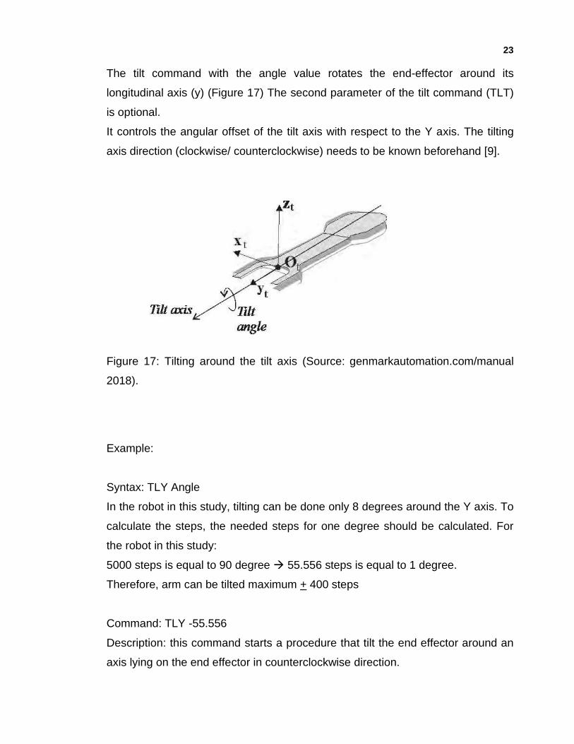
The tilt command with the angle value rotates the end-effector around its
longitudinal axis (y) (Figure 17) The second parameter of the tilt command (TLT)
is optional.
It controls the angular offset of the tilt axis with respect to the Y axis. The tilting
axis direction (clockwise/ counterclockwise) needs to be known beforehand [9].
Figure 17: Tilting around the tilt axis (Source: genmarkautomation.com/manual
2018).
Example:
Syntax: TLY Angle
In the robot in this study, tilting can be done only 8 degrees around the Y axis. To
calculate the steps, the needed steps for one degree should be calculated. For
the robot in this study:
5000 steps is equal to 90 degree → 55.556 steps is equal to 1 degree.
Therefore, arm can be tilted maximum + 400 steps
Command: TLY -55.556
Description: this command starts a procedure that tilt the end effector around an
axis lying on the end effector in counterclockwise direction.
24
6.7 Tilt around X access
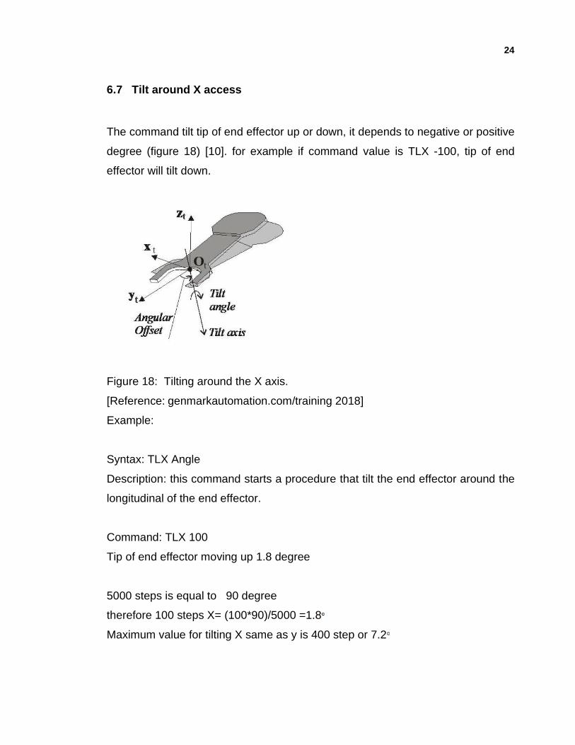
The command tilt tip of end effector up or down, it depends to negative or positive
degree (figure 18) [10]. for example if command value is TLX -100, tip of end
effector will tilt down.
Figure 18: Tilting around the X axis.
[Reference: genmarkautomation.com/training 2018]
Example:
Syntax: TLX Angle
Description: this command starts a procedure that tilt the end effector around the
longitudinal of the end effector.
Command: TLX 100
Tip of end effector moving up 1.8 degree
5000 steps is equal to 90 degree
therefore 100 steps X= (100*90)/5000 =1.8
Maximum value for tilting X same as y is 400 step or 7.2
25
7 MATERIAL DETECTION IN GENMARK
There are different methods for handling the wafers by robots. Robots handle the
wafer by mechanical gripping or vacuum. Genmark robot uses vacuum to hold
wafer on the end effector. Vacuum line from facility line or a vacuum pump should
be connected to robot by pneumatic pipe. The minimum vacuum need for holding
wafers by end effector is -500 mbar. There are two types of sensors used for
wafer searching during the execution of GET procedure named as pusher
sensors and vacuum sensors.
The pusher sensor is an electro-mechanical sensor which is activated when a
present wafer pushed. The vacuum sensor is checked for vacuum presence
when the vacuum valve is closed. When a wafer is present on the end effector,
vacuum sensor detects the wafer. If level of vacuum is less than 500 mbar, there
is a risk that wafer is not in the right position and for that reason the robot does
not move and alarm sounds rising for notification of the failure.
7.1 Vacuum sensor calibration
The vacuum sensor is a digital gauge located on the top flange or the arm link of
the robot. Proper calibration of all sensors needs to be observed during
installation.
By pressing the SET key on the pressure sensor [11], it returns to sensing unit of
pressure like pa, psi or bar. By selecting bar unit, the range would be between
(0-1000) mbar which appears in display. Main vacuum line needs to be
connected to input connector of manometer. To check the level of vacuum, a
wafer will be placed on the end effector and vacuum pipe line will be connected
to the output connector of manometer and the value can be compared with
vacuum sensor. If the read value is not same as the value shown on manometer,
26
the correct value can be achieved by changing the potentiometer with a
screwdriver.
The initial conditions can be set and stored in the EEPROM. It will not be erased
if the power is switched off [10].
7.2 Checking Vacuum by GenMark commands
In some cases, there is a need to check if a wafer is loaded or present on the end
effector. There is a dedicated command in the genmark robot command Set for
this purpose that solves this task. The WPC (Wafer Presence Check) command
detects the wafer presence by measuring the vacuum seal of the end effector.
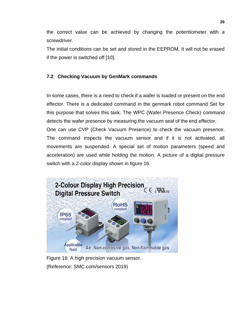
One can use CVP (Check Vacuum Presence) to check the vacuum presence.
The command inspects the vacuum sensor and if it is not activated, all
movements are suspended. A special set of motion parameters (speed and
acceleration) are used while holding the motion. A picture of a digital pressure
switch with a 2-color display shown in figure 16.
Figure 16: A high precision vacuum sensor.
(Reference: SMC.com/sensors 2019)
27
When vacuum level is above 500 mbar, color of 7 segment display is green, for
vacuum level less than 500 mbar, the color is red and error appears in screen
[11].
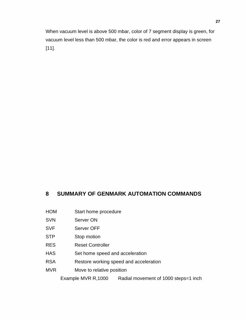
8 SUMMARY OF GENMARK AUTOMATION COMMANDS
HOM Start home procedure
SVN Server ON
SVF Server OFF
STP Stop motion
RES Reset Controller
HAS Set home speed and acceleration
RSA Restore working speed and acceleration
MVR Move to relative position
Example MVR R,1000 Radial movement of 1000 steps=1 inch
28
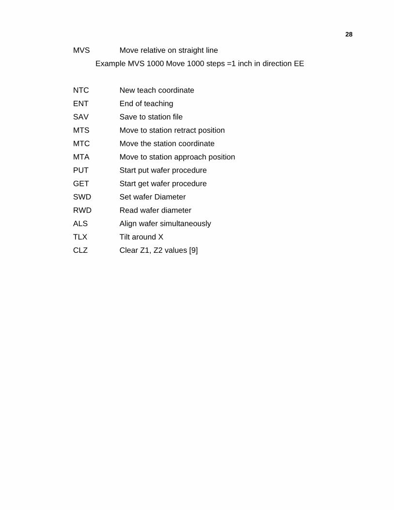
MVS Move relative on straight line
Example MVS 1000 Move 1000 steps =1 inch in direction EE
NTC New teach coordinate
ENT End of teaching
SAV Save to station file
MTS Move to station retract position
MTC Move the station coordinate
MTA Move to station approach position
PUT Start put wafer procedure
GET Start get wafer procedure
SWD Set wafer Diameter
RWD Read wafer diameter
ALS Align wafer simultaneously
TLX Tilt around X
CLZ Clear Z1, Z2 values [9]
29
9 TEACHING STATION AND POSITION FOR ROBOT
Before turning the power of the robot controller ON the following should be
checked [10].
a) Mechanical mounting and stability
b) Electrical connections
c) Utility connection
d) Communication connections
e) Communication utilities installed
f) Peripheral equipment and system
g) Limiting devices for restricting the maximum envelope
h) All personnel exit the restricted envelope prior to applying drive power.
After verifying all necessary items, the controller may be turned ON.
9.1 Station Name
The name of module location is represented by single letter from the english
alphabet like coat module location is A,a or bake module location is B,b. It is case
sensitive. The station name and parameters are unique for each station. The
usage of each station demands a teaching process.
If robot has two end effectors, usually end effector 0 represented by big English
alphabet like A, B, C, etc. and End effector 1 represented by small English
alphabet like a, b, c, etc.
30
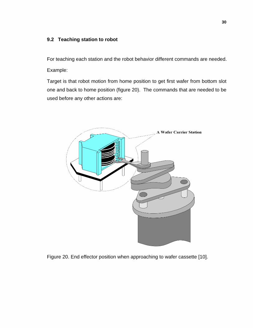
9.2 Teaching station to robot
For teaching each station and the robot behavior different commands are needed.
Example:
Target is that robot motion from home position to get first wafer from bottom slot
one and back to home position (figure 20). The commands that are needed to be
used before any other actions are:
Figure 20. End effector position when approaching to wafer cassette [10].
31
1. SVN: with this command controller gets ON. check the status of the controller
by checking the LED light. green light indicated that the controller is on and red
light shows the controller is off.
2. HOM: robot starts initializing and moving to home position.
3. HSA: reduces robot speed from normal speed in which robot moves 10 mm/s.
With using this command, robot will start to move 5 mm/s. Usually this
command is very useful when there is a need to teach the stations. Lower
speed prevents the risk of crashing of the end effectors to other parts of the
tool.
After checking homing and reducing the robot speed, the commands that are
needed to teach the position will be used.
4. MTA A: move to approach. With this command end effector (EEF) approaches
the target position which is station A in this example. Assume that end
effector’s current position is 200 mm below and 300 mm far from wafer slot 1
inside the cassette.
5. MVR Z, 80000:
200mm*400 step=80,000 step (1mm= 400 stapes)
By using this command, EEF will move 80,000 steps from current position.
It should be noted that before pressing enter for all movement commands, it is
recommended to be prepared to stop robot immediately by pressing F9. After
applying the command, tip of EEF and first wafer in the cassette must be same
level.
6. MVR R, 110,000: EEF will move in R direction (straight) to approach the first
wafer in the cassette but not exactly touching the wafer.
Let’s assume that diameter of the wafer is 200 mm and its thickness is 0.8
mm. If after applying the commands, the EEF is in the same level as surface of
the wafer, it should move down in z axis 0.8+0.2 mm to pick up position.
7. MVR Z, -400: EEF will move 1 mm down to pick up position.
32
8. MVR R, 1000: surface of EEF moves forward to be 200 µm under the wafer.
9. MVR R, 80000: EEF is under wafer and ready to pick up
10. OUT 1,2: EEF 0 vacuum on to keep wafer in place during the EEF movement.
OUT command means vacuum and first value after out indicates, EEF number
and second value turning vacuum valve ON or OFF.
11. MVR Z, 800: picks up the wafer by moving up and holding wafer on EEF.
12. NTC: new teaching station.
13. SAV: saves the station.
14. END: end of teaching position.
15. MTS: moving back to home position.
Now in controller station A is saved.
For checking new trained status, the robot can be adjusted to normal speed by
using the (RSA) Command. By applying the commands that are mentioned
below, the trained position can be checked.
GET A,1: with this command robot will pick up the wafer from station A slot 1.
PUT A,1: robot will put the wafer back to station A slot 1.
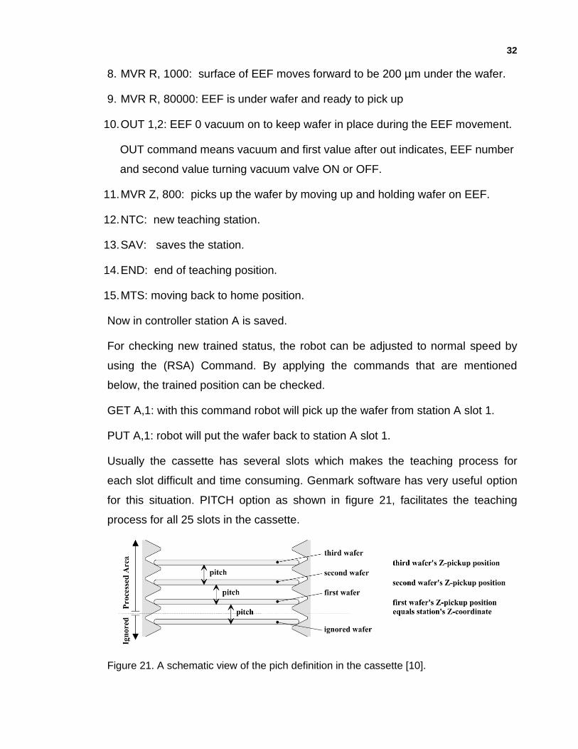
Usually the cassette has several slots which makes the teaching process for
each slot difficult and time consuming. Genmark software has very useful option
for this situation. PITCH option as shown in figure 21, facilitates the teaching
process for all 25 slots in the cassette.
Figure 21. A schematic view of the pich definition in the cassette [10].
33
By using the pitch, the pickup position for wafer in slot i, is calculated according to the
following formula:
Zppi = {Zpp1+( i-1) *pitch} /25
in this formula Zppi is pickup position and pitch value divided by 25 wafers inside the
cassette.
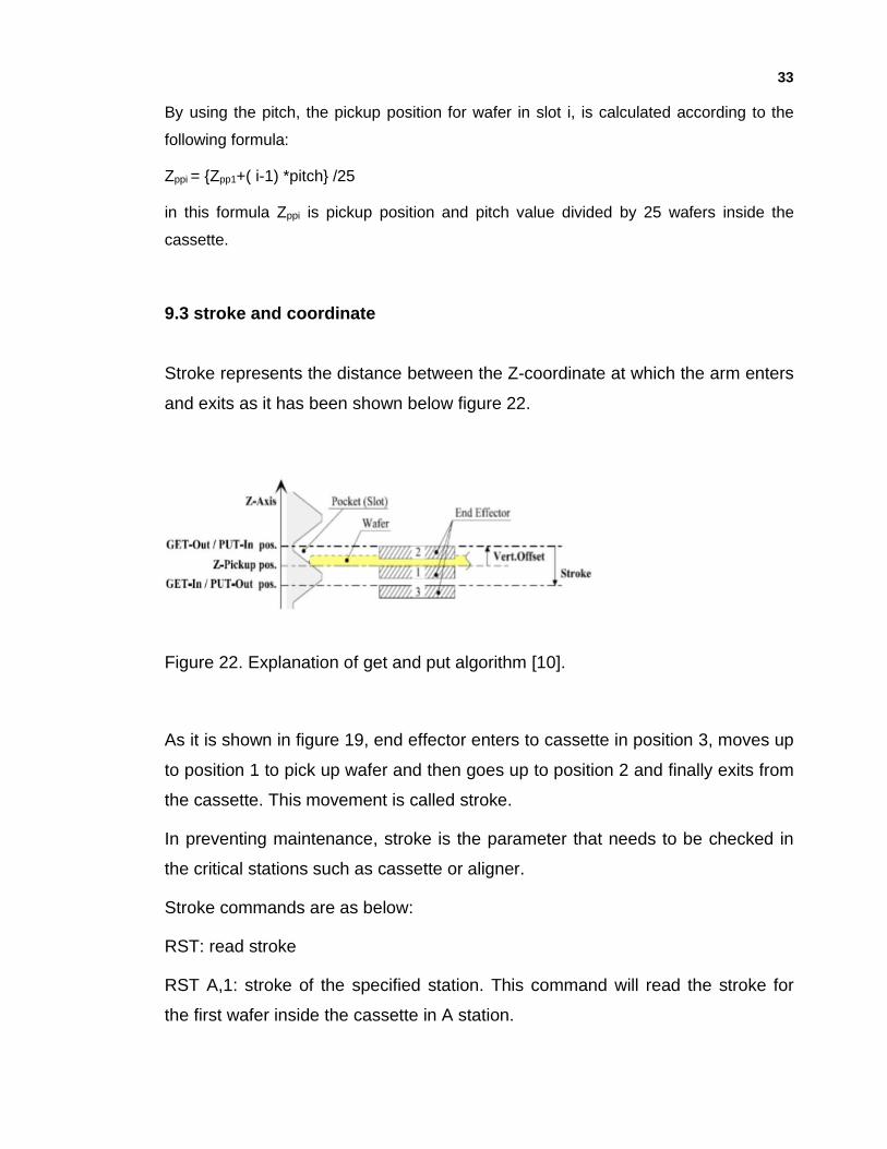
9.3 stroke and coordinate
Stroke represents the distance between the Z-coordinate at which the arm enters
and exits as it has been shown below figure 22.
Figure 22. Explanation of get and put algorithm [10].
As it is shown in figure 19, end effector enters to cassette in position 3, moves up
to position 1 to pick up wafer and then goes up to position 2 and finally exits from
the cassette. This movement is called stroke.
In preventing maintenance, stroke is the parameter that needs to be checked in
the critical stations such as cassette or aligner.
Stroke commands are as below:
RST: read stroke
RST A,1: stroke of the specified station. This command will read the stroke for
the first wafer inside the cassette in A station.
34
SST: set stroke
Total distance from between get in, pick up material, move up and get back is
called stroke. usually material is same coordinate position as end effector.
For example, SST A 600 means that from coordinate position 300 steps down
(pick up position) and 300 steps up (get out and back to home position).
10 ROBOT END EFFECTORS
End effectors are the parts of robots that are in contact with the wafers. End
effectors can employ different methods for product handling. These methods
include, but are not limited to, clamp style, fork style, vacuum style and other
custom designs.
Two types of end effector as shown in figure 23 and 24 designed in PTC software
for handling process.
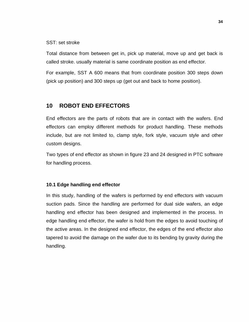
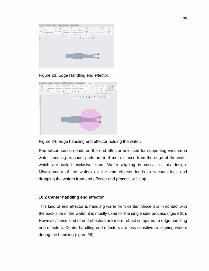
10.1 Edge handling end effector
In this study, handling of the wafers is performed by end effectors with vacuum
suction pads. Since the handling are performed for dual side wafers, an edge
handling end effector has been designed and implemented in the process. In
edge handling end effector, the wafer is hold from the edges to avoid touching of
the active areas. In the designed end effector, the edges of the end effector also
tapered to avoid the damage on the wafer due to its bending by gravity during the
handling.
35
Figure 23. Edge Handling end effector.
Figure 24: Edge handling end effector holding the wafer.
Red silicon suction pads on the end effector are used for supporting vacuum in
wafer handling. Vacuum pads are in 4 mm distance from the edge of the wafer
which are called exclusive zone. Wafer aligning is critical in this design.
Misalignment of the wafers on the end effector leads to vacuum leak and
dropping the wafers from end effector and process will stop.
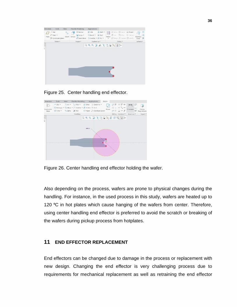
10.2 Center handling end effector
This kind of end effector is handling wafer from center. Since it is in contact with
the back side of the wafer, it is mostly used for the single side process (figure 25).
However, these kind of end effectors are more robust compared to edge handling
end effectors. Center handling end effectors are less sensitive to aligning wafers
during the handling (figure 26).
36
Figure 25. Center handling end effector.
Figure 26. Center handling end effector holding the wafer.
Also depending on the process, wafers are prone to physical changes during the
handling. For instance, in the used process in this study, wafers are heated up to
120 ⁰C in hot plates which cause hanging of the wafers from center. Therefore,
using center handling end effector is preferred to avoid the scratch or breaking of
the wafers during pickup process from hotplates.
11 END EFFECTOR REPLACEMENT
End effectors can be changed due to damage in the process or replacement with
new design. Changing the end effector is very challenging process due to
requirements for mechanical replacement as well as retraining the end effector
37
for all the process stations. Usually, replacement of the end effector requires the
24 hours of tool down time. Here, the replacement steps are explained in detail:
1. Drive end effector to prealinger in coordinate position.
• run genmark software and click train mood and write SVN. With this
command controller turns on.
• MTC P: with this command end effector will move to coordinate position to
prealigner.
2. Disassembling:
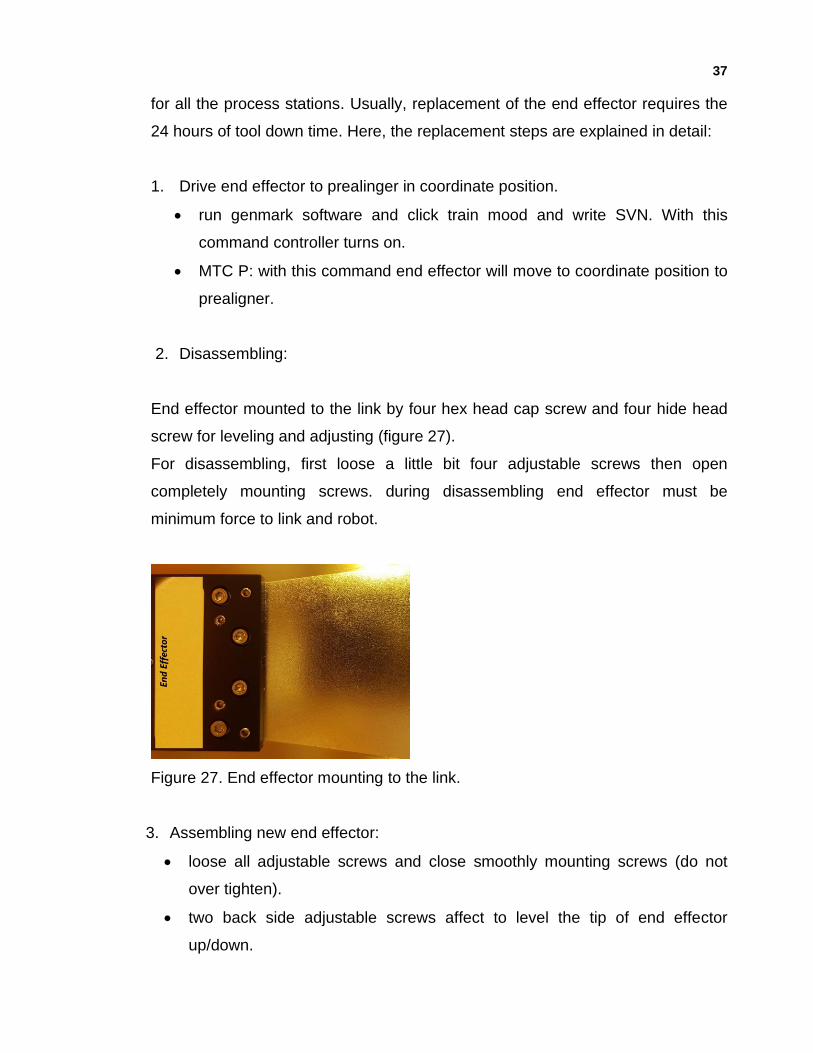
End effector mounted to the link by four hex head cap screw and four hide head
screw for leveling and adjusting (figure 27).
For disassembling, first loose a little bit four adjustable screws then open
completely mounting screws. during disassembling end effector must be
minimum force to link and robot.
Figure 27. End effector mounting to the link.
3. Assembling new end effector:
• loose all adjustable screws and close smoothly mounting screws (do not
over tighten).
• two back side adjustable screws affect to level the tip of end effector
up/down.
38
• two front adjustable screws affect to tilt of end effector in clock or
counterclockwise direction (figure 24).
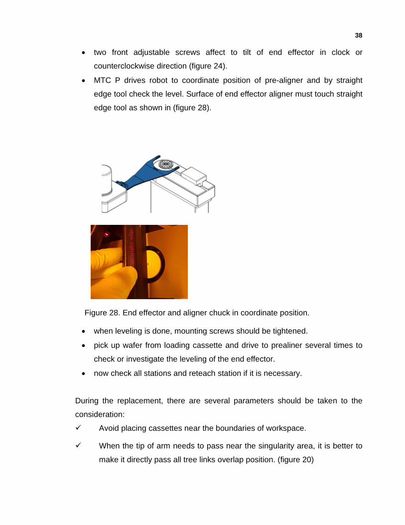
• MTC P drives robot to coordinate position of pre-aligner and by straight
edge tool check the level. Surface of end effector aligner must touch straight
edge tool as shown in (figure 28).
Figure 28. End effector and aligner chuck in coordinate position.
• when leveling is done, mounting screws should be tightened.
• pick up wafer from loading cassette and drive to prealiner several times to
check or investigate the leveling of the end effector.
• now check all stations and reteach station if it is necessary.
During the replacement, there are several parameters should be taken to the
consideration:
✓ Avoid placing cassettes near the boundaries of workspace.
✓ When the tip of arm needs to pass near the singularity area, it is better to
make it directly pass all tree links overlap position. (figure 20)
39
✓ Check for the radial placement of cassettes in radial steps, after using
TLT. If the mechanical design includes E-axis, use MVA E instead of TLT
command to compensate the gimbal misalignment of the cassettes.
12 PREVENTIVE MAINTENANCE FOR ROBOT
Robot handling is one of the critical parts of the process which impacts the quality
of the product. Therefore, maintenance scheduling is important to maintain the
quality of handling during the process. it also increases the robot lifetime.
Preventive maintenance steps:
1. Clean all end effector surfaces with a sealed border or lent free wipe and
isopropanol. Since the end effector is a moving part in the process, it can
increase the risk of particle contamination on the wafers. However, end effectors
are sensitive to applied pressure and their position might change by pressure.
Therefore, cleaning process should be performed smoothly.
2. Inspect the vacuum sealing lips of each end effector.
Wafer is hold by suction pads on the end effectors. The quality of the pads
guarantees the vacuum support on the wafer. Depending on the suction pads
material, there is a need to change the vacuum pads in certain intervals.
3. Clean and Lubricate robot
Robot has three bonds to hold and move platform in Z direction (up/down)
through the vertical bearings. Bearings needs to be cleaned from old grease and
renew in monthly intervals.
4. check vacuum level.
Vacuum line, filter and valve needs to be inspected for preventing the blockage of
the lines by particles every three months. Vacuum level will be checked by
manometer and the vacuum filter will be replaced.
40
13 CONCLUSION
In this thesis, Genmark robot installation and handling process for dual wafer
handling are reviewed. Robot movement mechanism and different mechanical
parts of the robot is explained. Also, installation of robot has been reviewed.
Ramping of the robot was briefly discussed. Robot needs to be trained for wafer
handling and it depends on the process. The teaching commands for the wafer
handling by using vacuum handling end effectors were explained in detail.
I explained that the robot handling is very sensitive to other involved modules and
its scheduling depends on those modules performance. Robot handling is also
playing an important role in the cycle time of the process. If the scheduling and
teaching is not defined in an appropriate manner, it becomes as a bottleneck in
cycle time. Since robots are providing the handling without manual interface, the
teaching is critical in the quality. For instance, if teaching is not accurate, the
handling causes defects such as scratches and breaking the wafer which will
decrease the yield dramatically in the production. In the robot teaching, various
examples from different commands were provided. The process dependency of
the robot teaching such as the wafer thickness, environment, requirements for
accurate alignment has been discussed.
41
REFERENCES
1. M. Edwards, Robots in industry: An overview, Appl. Ergonomics. 1984. Vol.15.
P 45-53.
2. O. Khatib , J. Burdick, Motion and force control of robot manipulators.
Proceedings in IEEE International Conference on Robotics and
Automation.1986.
3. www.integritycleanroom.com [cited on 16.12.2019]. D. Ensor, R. Donovan, B.
Locke, Particle size distributions in cleanrooms.J.Environmental Sci. 1987. Vol
30, P. 44-49.
4. Cleanroom classification, https://www.mecart-cleanrooms.com/learning-
center/cleanroom-classifications-iso-8-iso-7-iso-6-iso-5/. [Cited on 25.8.2019].
5. S. Premkumar, K. Surya Varman, R. Balamurugan, Design and
implementation of multi handling pick and place robotic arm. International
Journal of Engineering Trends and Technology (IJETT). March 2016. Vol. 33.
6. www.genmarkautomation.com [cited on 16.12.2019]A. Elfasakhany, E. Yanez,
K. Baylon, R. Salgado, Design and development of a competitive low-cost
robot arm with four degrees of freedom. Modern Mechanical Eng. 2011. Vol.1.
P.47-55.
7. V. Hlaváč, Robot kinematics,
http://people.ciirc.cvut.cz/~hlavac/TeachPresEn/55AutonomRobotics/020Kine
maticsEn.pdf, [Cited on 10.4.2019].
8. www.genmarkautomation.com 2019.
9. Z. Sotirov, high-performance wafer handling systems for semiconductor
automation, Genmark Automation, Inc.
10. EVG Group Company, https://www.evgroup.com. [Cited on 4.4.2019].
11. SMC Company, https://www.SMC.com. [Cited on 18.9.2019].