karsten fischer - p+f wirelesshart products overvie · wirelesshart products overview karsten...
TRANSCRIPT

THE PEPPERL+FUCHS GROUPTHE PEPPERL+FUCHS GROUPWirelessHART Products Overview
Karsten Fischer - Global Account Manager Invensys
Thomas Klatt/Gerrit Lohmann page 207.09.2009
TopicsTopics
OverviewWirelessHART GatewayWirelessHART AdaptorWirelessHART Temperature Transmitter
Thomas Klatt/Gerrit Lohmann page 307.09.2009
WirelessHART Device TypesWirelessHART Device Types
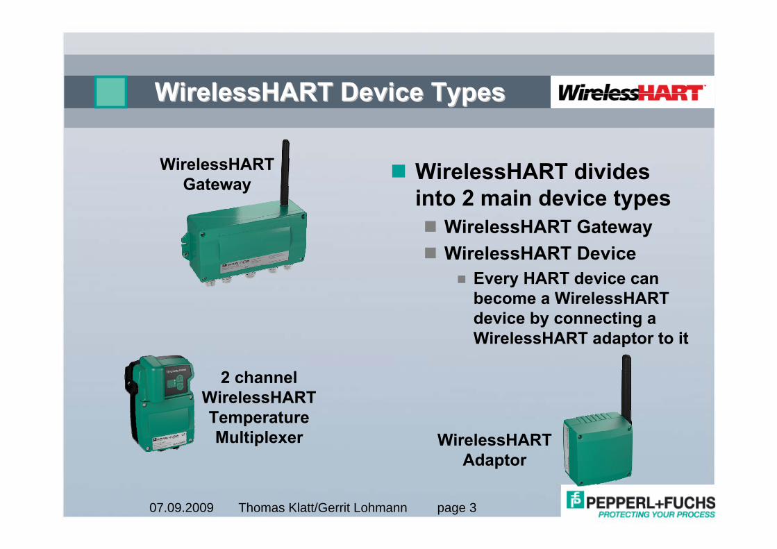
WirelessHART divides into 2 main device types
WirelessHART GatewayWirelessHART Device
Every HART device can become a WirelessHART device by connecting a WirelessHART adaptor to it
WirelessHARTGateway
2 channelWirelessHARTTemperatureMultiplexer WirelessHART
Adaptor
Thomas Klatt/Gerrit Lohmann page 407.09.2009
WirelessHART GatewayWirelessHART Gateway
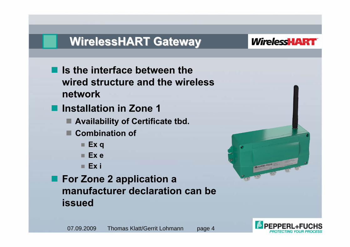
Is the interface between the wired structure and the wireless networkInstallation in Zone 1
Availability of Certificate tbd.Combination of
Ex qEx eEx i
For Zone 2 application a manufacturer declaration can be issued
Thomas Klatt/Gerrit Lohmann page 507.09.2009
WirelessHART GatewayWirelessHART Gateway
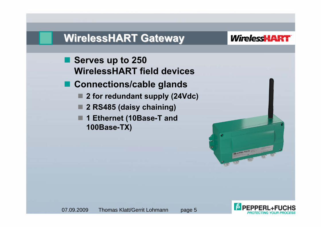
Serves up to 250 WirelessHART field devicesConnections/cable glands
2 for redundant supply (24Vdc)2 RS485 (daisy chaining)1 Ethernet (10Base-T and 100Base-TX)
Thomas Klatt/Gerrit Lohmann page 607.09.2009
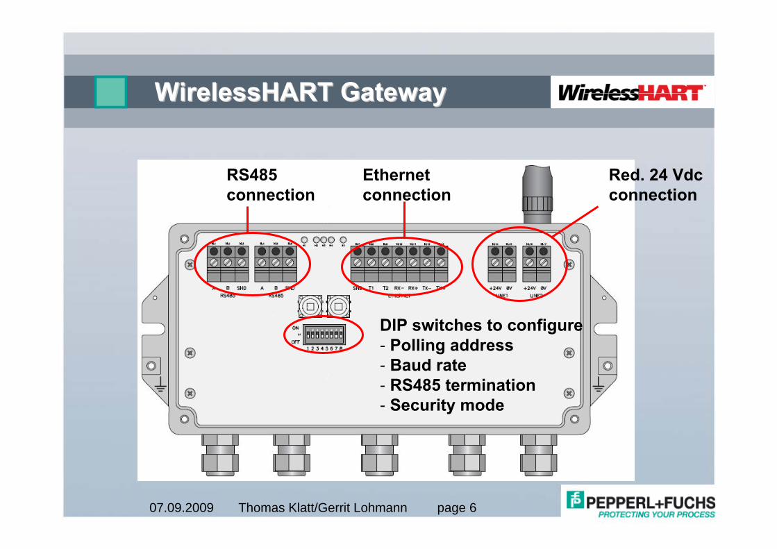
WirelessHART GatewayWirelessHART Gateway
Red. 24 Vdcconnection
Ethernetconnection
RS485connection
DIP switches to configure- Polling address- Baud rate- RS485 termination- Security mode
Thomas Klatt/Gerrit Lohmann page 707.09.2009
RS485 InterfaceRS485 Interface
2 Terminals blocks to have “daisy chain”capabilityIn case WirelessHART GW is the RS485 participant on the bus
RS485 terminator must be switched onVia DIP switch 7 = ON
ORVia (software) configuration settings
Supported baud rates via RS4859600, 19200, 38400 or 57600 kBaudVia DIP switch 5&6 or (software) configuration settings
Thomas Klatt/Gerrit Lohmann page 807.09.2009
RS485 InterfaceRS485 Interface
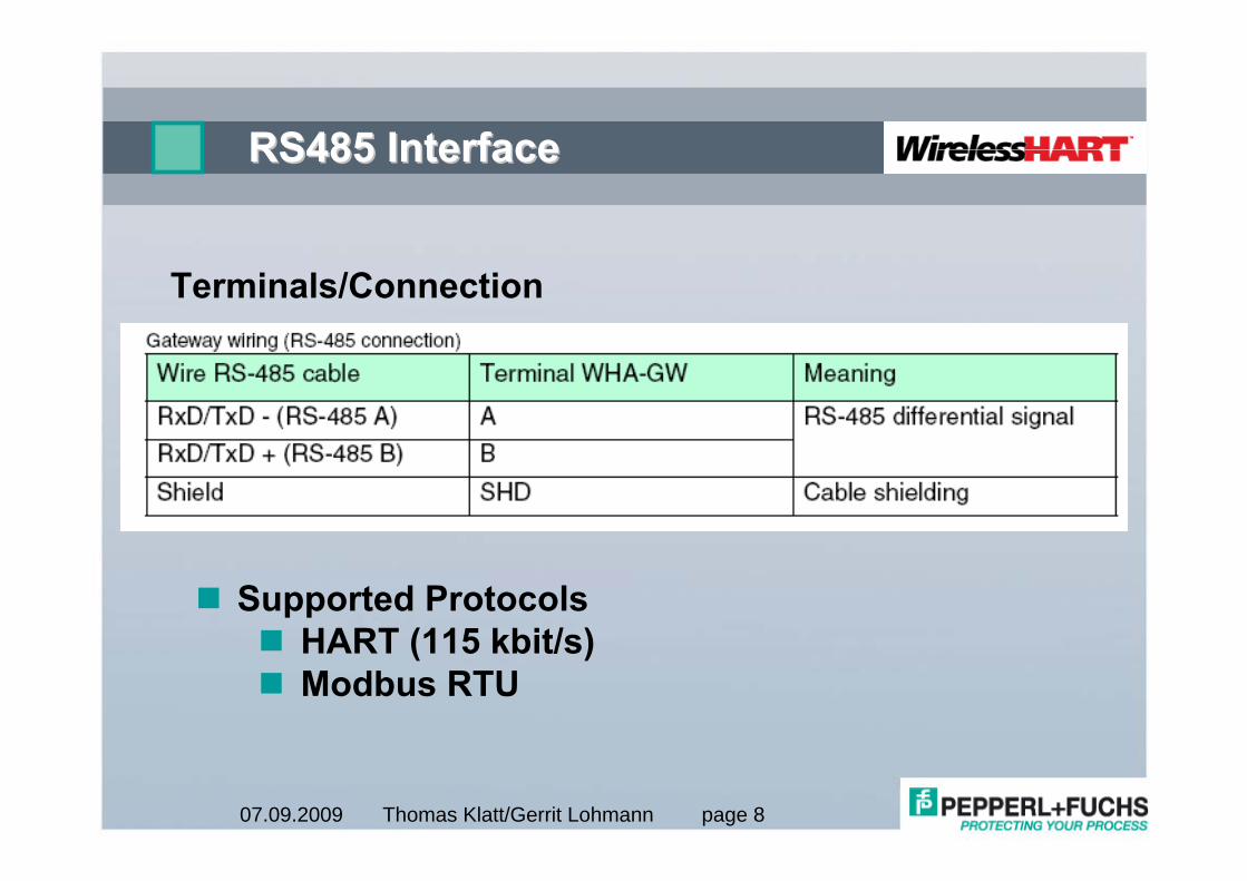
Terminals/Connection
Supported ProtocolsHART (115 kbit/s)Modbus RTU
Thomas Klatt/Gerrit Lohmann page 907.09.2009
RS485 InterfaceRS485 Interface
RS485 polling address can be configured via DIP switches 1 to 4
Addresses 0 to 15RS485 polling addresses can also be configured via (software) configuration settings
Must be used in case higher addresses than 15 are requiredHighest possible addresses
HART protocol 63Modbus RTU 247
Thomas Klatt/Gerrit Lohmann page 1007.09.2009
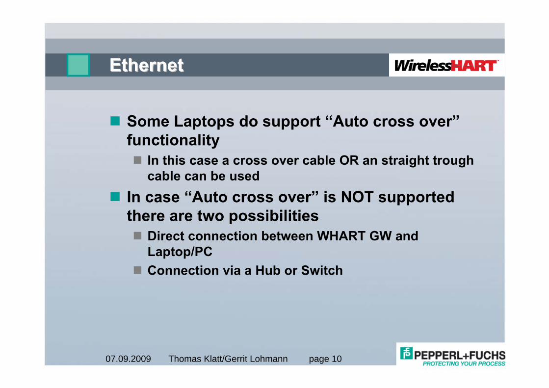
EthernetEthernet
Some Laptops do support “Auto cross over”functionality
In this case a cross over cable OR an straight trough cable can be used
In case “Auto cross over” is NOT supported there are two possibilities
Direct connection between WHART GW and Laptop/PCConnection via a Hub or Switch
Thomas Klatt/Gerrit Lohmann page 1107.09.2009
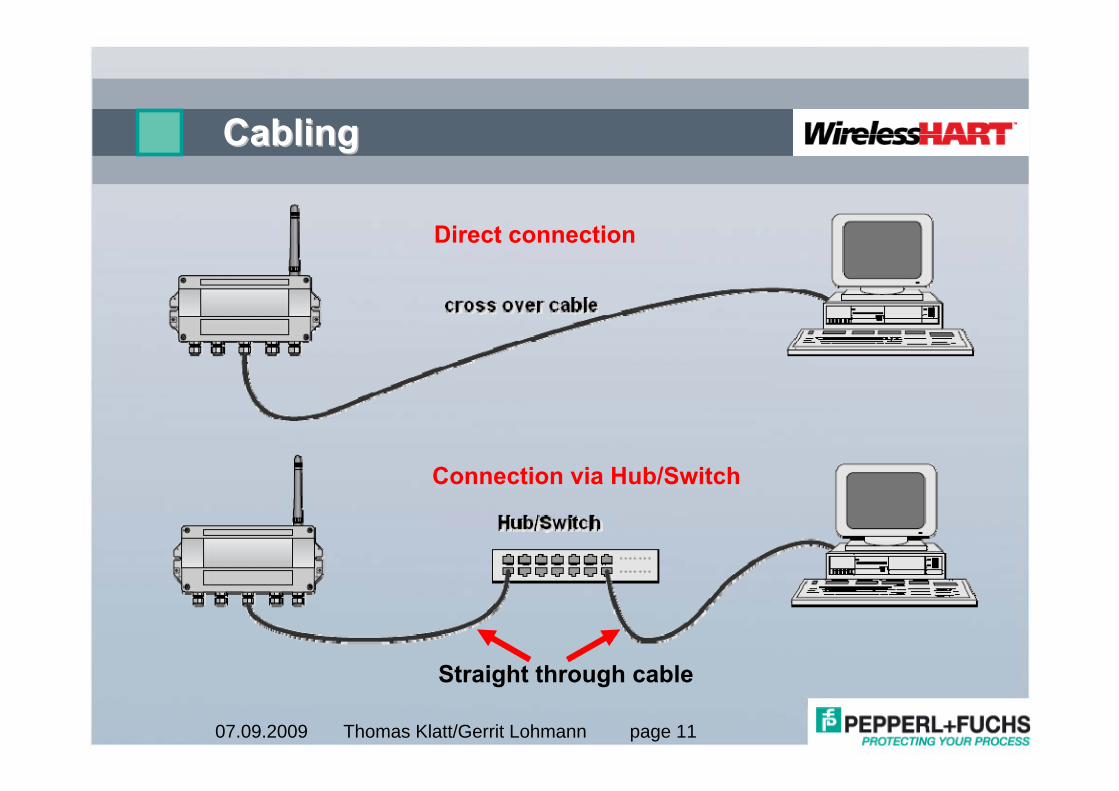
CablingCabling
Direct connection
Connection via Hub/Switch
Straight through cable
Thomas Klatt/Gerrit Lohmann page 1207.09.2009
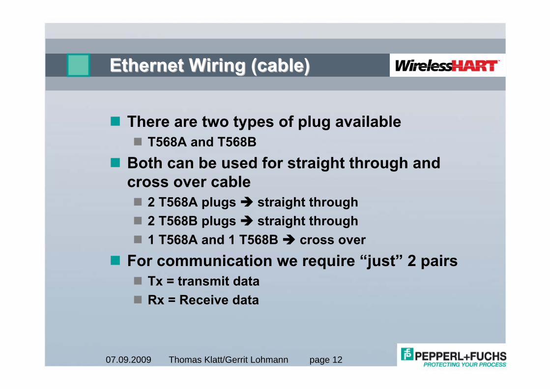
Ethernet Wiring (cable)Ethernet Wiring (cable)
There are two types of plug availableT568A and T568B
Both can be used for straight through and cross over cable
2 T568A plugs straight through2 T568B plugs straight through1 T568A and 1 T568B cross over
For communication we require “just” 2 pairsTx = transmit dataRx = Receive data
Thomas Klatt/Gerrit Lohmann page 1307.09.2009
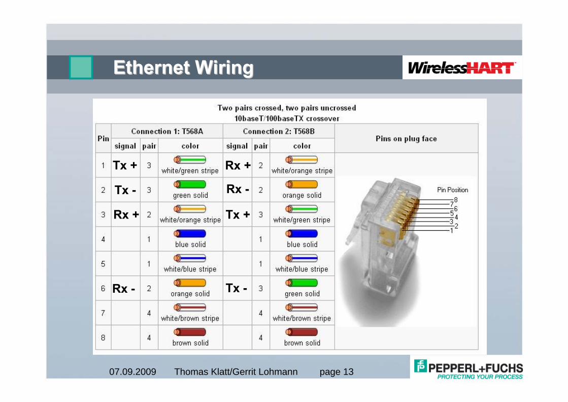
Ethernet WiringEthernet Wiring
Tx +
Tx -
Tx -
Tx +Rx +
Rx +
Rx -
Rx -
Thomas Klatt/Gerrit Lohmann page 1407.09.2009
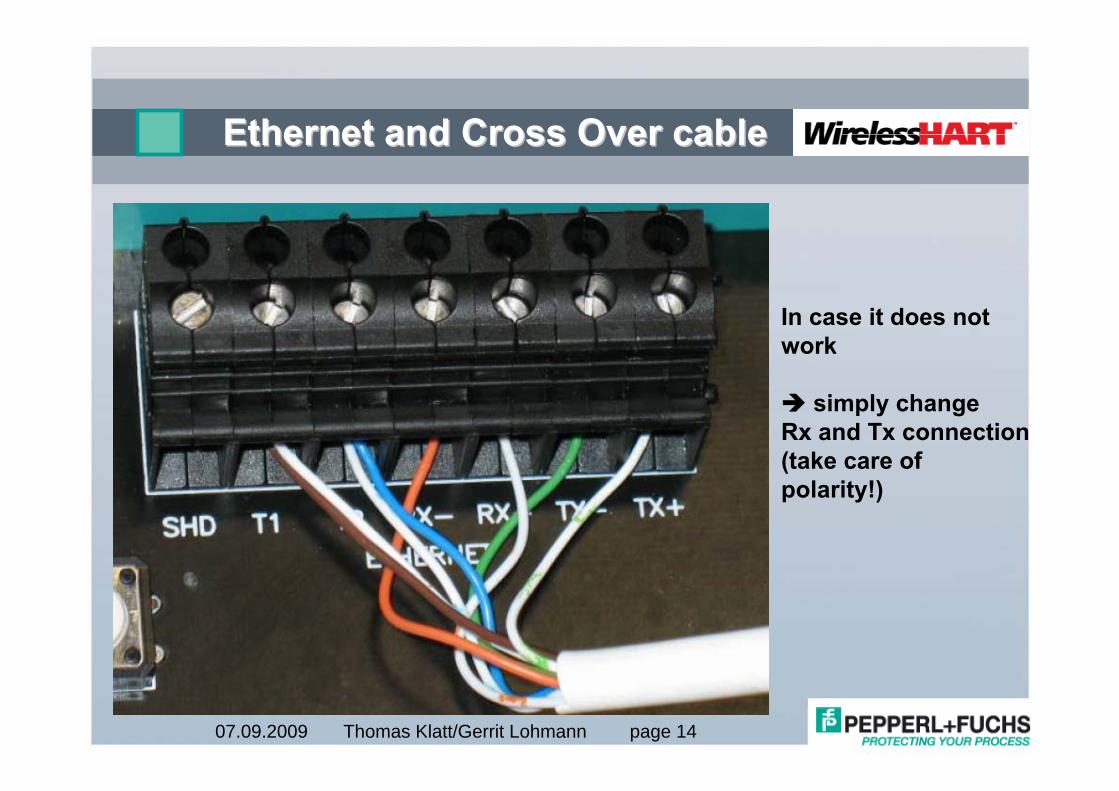
Ethernet and Cross Over cableEthernet and Cross Over cable
In case it does notwork
simply changeRx and Tx connection(take care ofpolarity!)
Thomas Klatt/Gerrit Lohmann page 1507.09.2009
Ethernet Ethernet IntefaceInteface
Supported Protocols via EthernetHART via UDPModbus TCP/IP
Transmission rate 100MBit/sAdditionally you can have access to the Web server via the Ethernet interface
Thomas Klatt/Gerrit Lohmann page 1607.09.2009
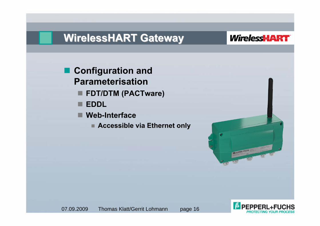
WirelessHART GatewayWirelessHART Gateway
Configuration and Parameterisation
FDT/DTM (PACTware)EDDLWeb-Interface
Accessible via Ethernet only
Thomas Klatt/Gerrit Lohmann page 1707.09.2009
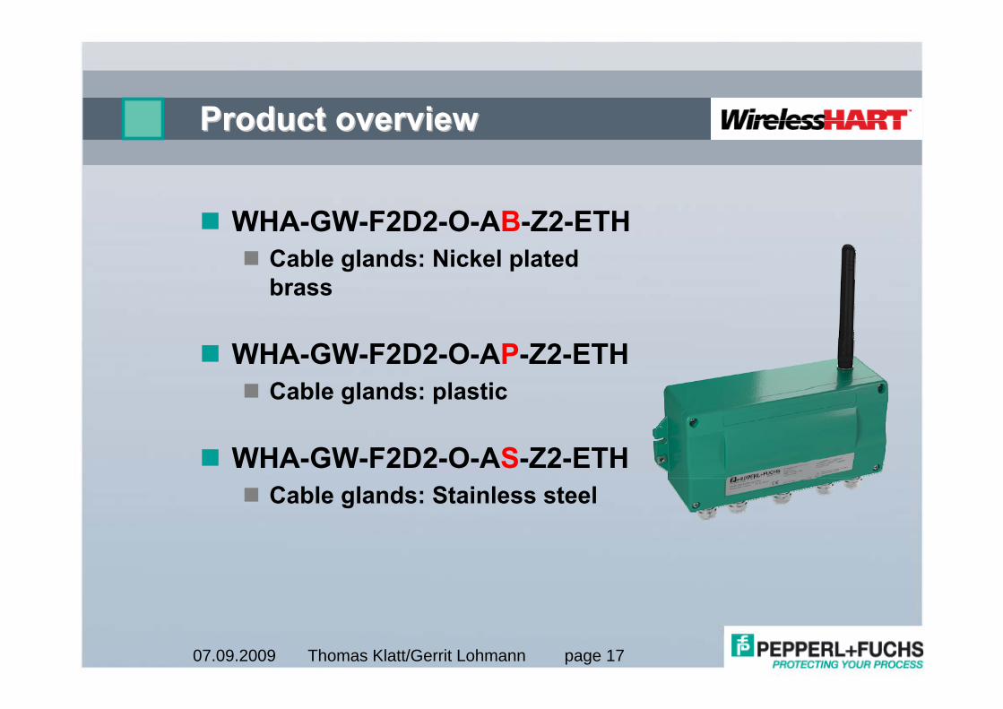
Product overviewProduct overview
WHA-GW-F2D2-O-AB-Z2-ETHCable glands: Nickel plated brass
WHA-GW-F2D2-O-AP-Z2-ETHCable glands: plastic
WHA-GW-F2D2-O-AS-Z2-ETHCable glands: Stainless steel
Thomas Klatt/Gerrit Lohmann page 1807.09.2009
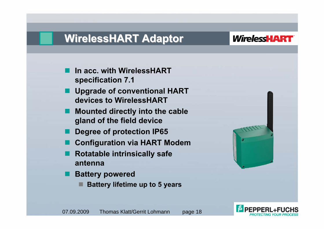
WirelessHART AdaptorWirelessHART Adaptor
In acc. with WirelessHART specification 7.1Upgrade of conventional HART devices to WirelessHARTMounted directly into the cable gland of the field deviceDegree of protection IP65Configuration via HART ModemRotatable intrinsically safe antennaBattery powered
Battery lifetime up to 5 years
Thomas Klatt/Gerrit Lohmann page 1907.09.2009
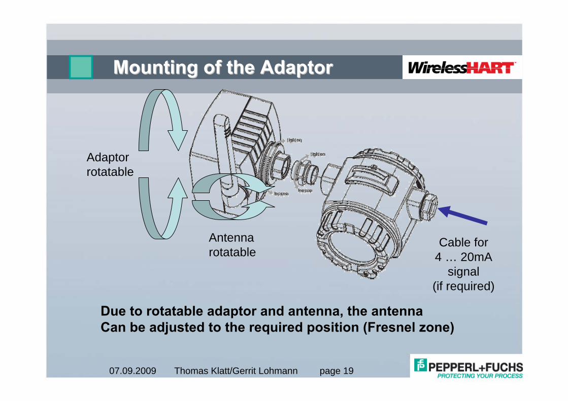
Mounting of the AdaptorMounting of the Adaptor
Adaptorrotatable
Antennarotatable
Due to rotatable adaptor and antenna, the antennaCan be adjusted to the required position (Fresnel zone)
Cable for4 … 20mA
signal(if required)
Thomas Klatt/Gerrit Lohmann page 2007.09.2009
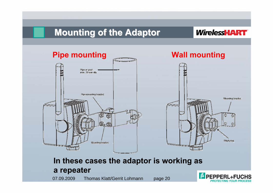
Mounting of the AdaptorMounting of the Adaptor
Pipe mounting Wall mounting
In these cases the adaptor is working asa repeater
Thomas Klatt/Gerrit Lohmann page 2107.09.2009
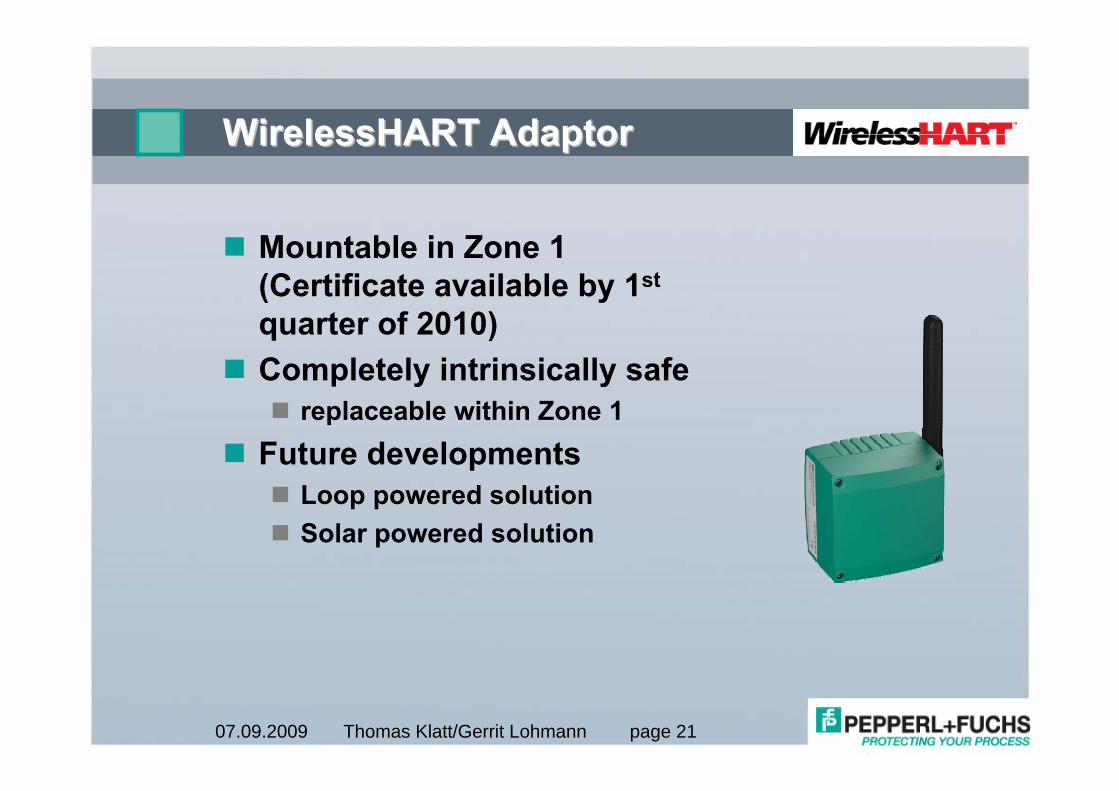
WirelessHART AdaptorWirelessHART Adaptor
Mountable in Zone 1(Certificate available by 1st
quarter of 2010)Completely intrinsically safe
replaceable within Zone 1Future developments
Loop powered solutionSolar powered solution
Thomas Klatt/Gerrit Lohmann page 2207.09.2009
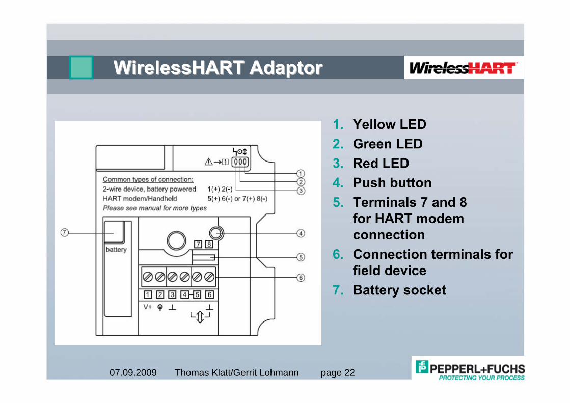
WirelessHART AdaptorWirelessHART Adaptor
1. Yellow LED2. Green LED3. Red LED4. Push button5. Terminals 7 and 8
for HART modem connection
6. Connection terminals for field device
7. Battery socket
Thomas Klatt/Gerrit Lohmann page 2307.09.2009
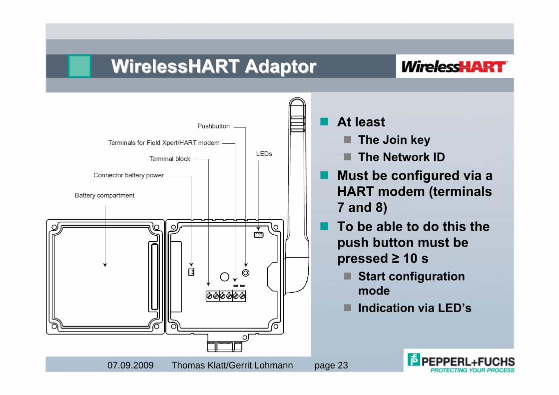
WirelessHART AdaptorWirelessHART Adaptor
At leastThe Join keyThe Network ID
Must be configured via a HART modem (terminals 7 and 8)To be able to do this the push button must be pressed ≥ 10 s
Start configuration modeIndication via LED’s
Thomas Klatt/Gerrit Lohmann page 2407.09.2009
WirelessHART AdaptorWirelessHART Adaptor
The adaptor will always be powered by the battery
2 batteries (located in the cover), connected in seriesEach offers 3.6V and 19Ah
The instrument can be fed fromBattery (Battery life time!)
Passive two wire deviceExternally
Active four wire deviceLoop powered
Two wire device with external powerConnected to an existing 4 … 20 mA loop
HART device with external power
Thomas Klatt/Gerrit Lohmann page 2507.09.2009
WirelessHART AdaptorWirelessHART Adaptor
Thomas Klatt/Gerrit Lohmann page 2607.09.2009
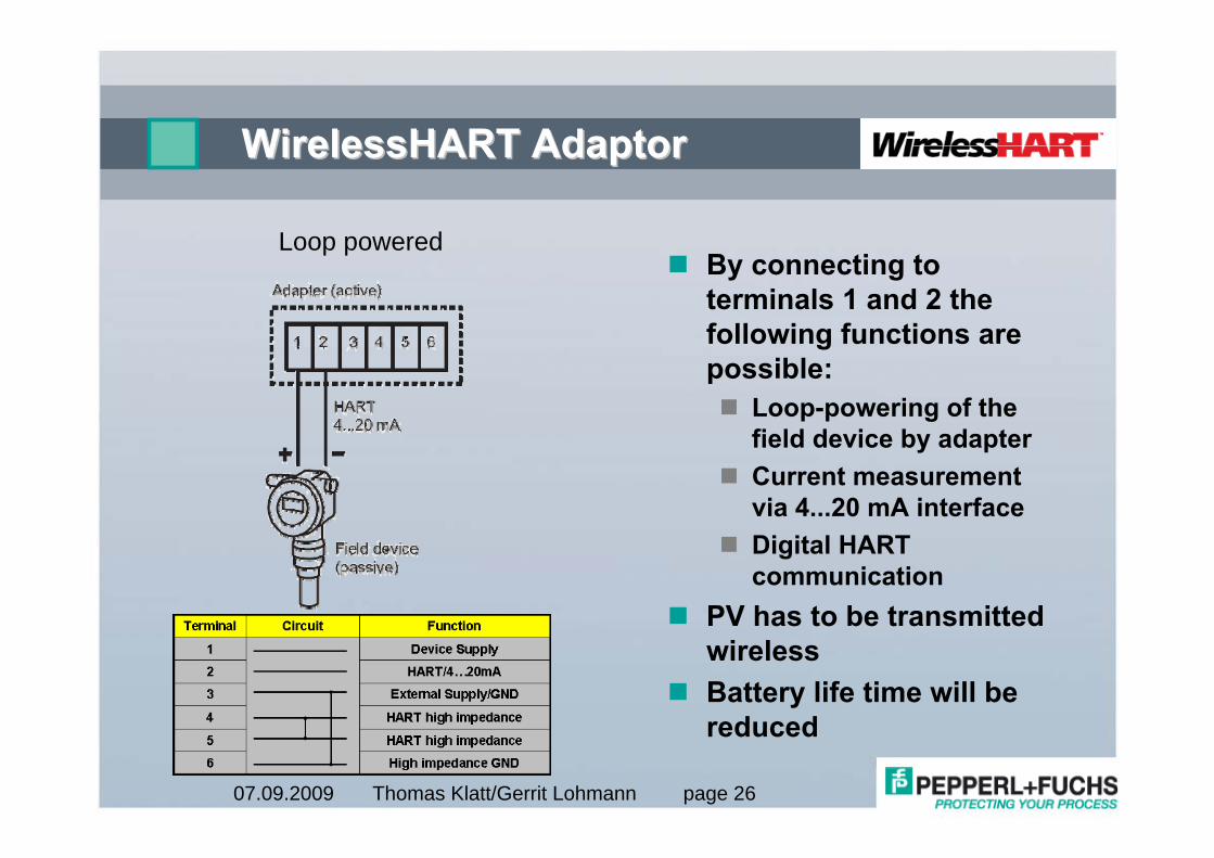
WirelessHART AdaptorWirelessHART Adaptor
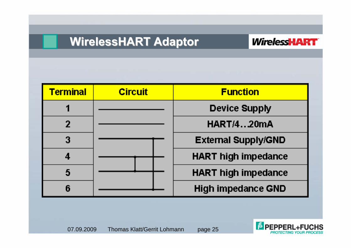
By connecting to terminals 1 and 2 the following functions are possible:
Loop-powering of the field device by adapterCurrent measurement via 4...20 mA interfaceDigital HART communication
PV has to be transmitted wirelessBattery life time will be reduced
Loop powered
Thomas Klatt/Gerrit Lohmann page 2707.09.2009
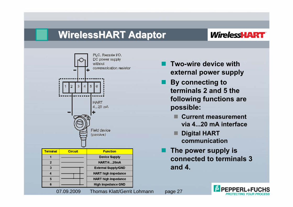
WirelessHART AdaptorWirelessHART Adaptor
Two-wire device with external power supplyBy connecting to terminals 2 and 5 the following functions are possible:
Current measurement via 4...20 mA interfaceDigital HART communication
The power supply is connected to terminals 3 and 4.
Thomas Klatt/Gerrit Lohmann page 2807.09.2009
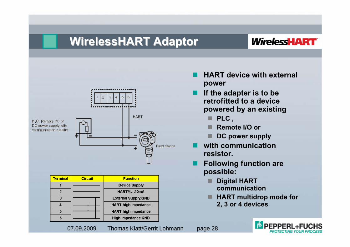
WirelessHART AdaptorWirelessHART Adaptor
HART device with external powerIf the adapter is to be retrofitted to a device powered by an existing
PLC ,Remote I/O orDC power supply
with communication resistor.Following function are possible:
Digital HART communicationHART multidrop mode for 2, 3 or 4 devices
Thomas Klatt/Gerrit Lohmann page 2907.09.2009
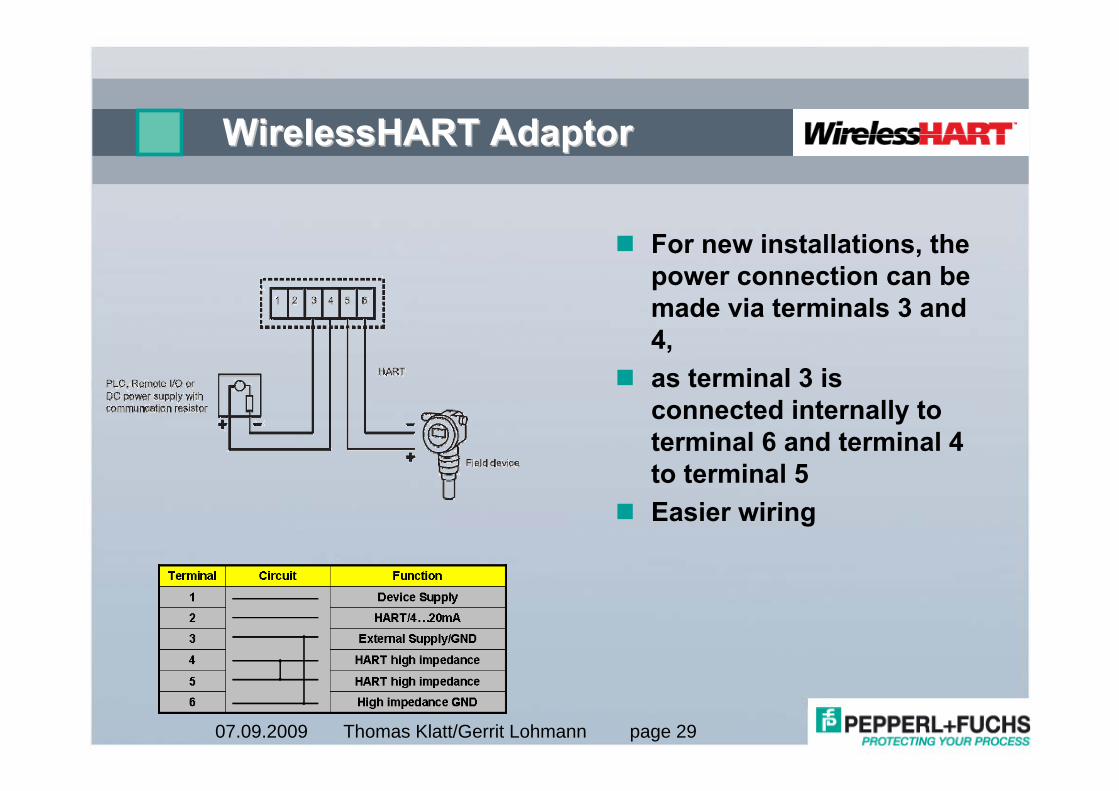
WirelessHART AdaptorWirelessHART Adaptor
For new installations, the power connection can be made via terminals 3 and 4, as terminal 3 is connected internally to terminal 6 and terminal 4 to terminal 5Easier wiring
Thomas Klatt/Gerrit Lohmann page 3007.09.2009
WirelessHART AdaptorWirelessHART Adaptor
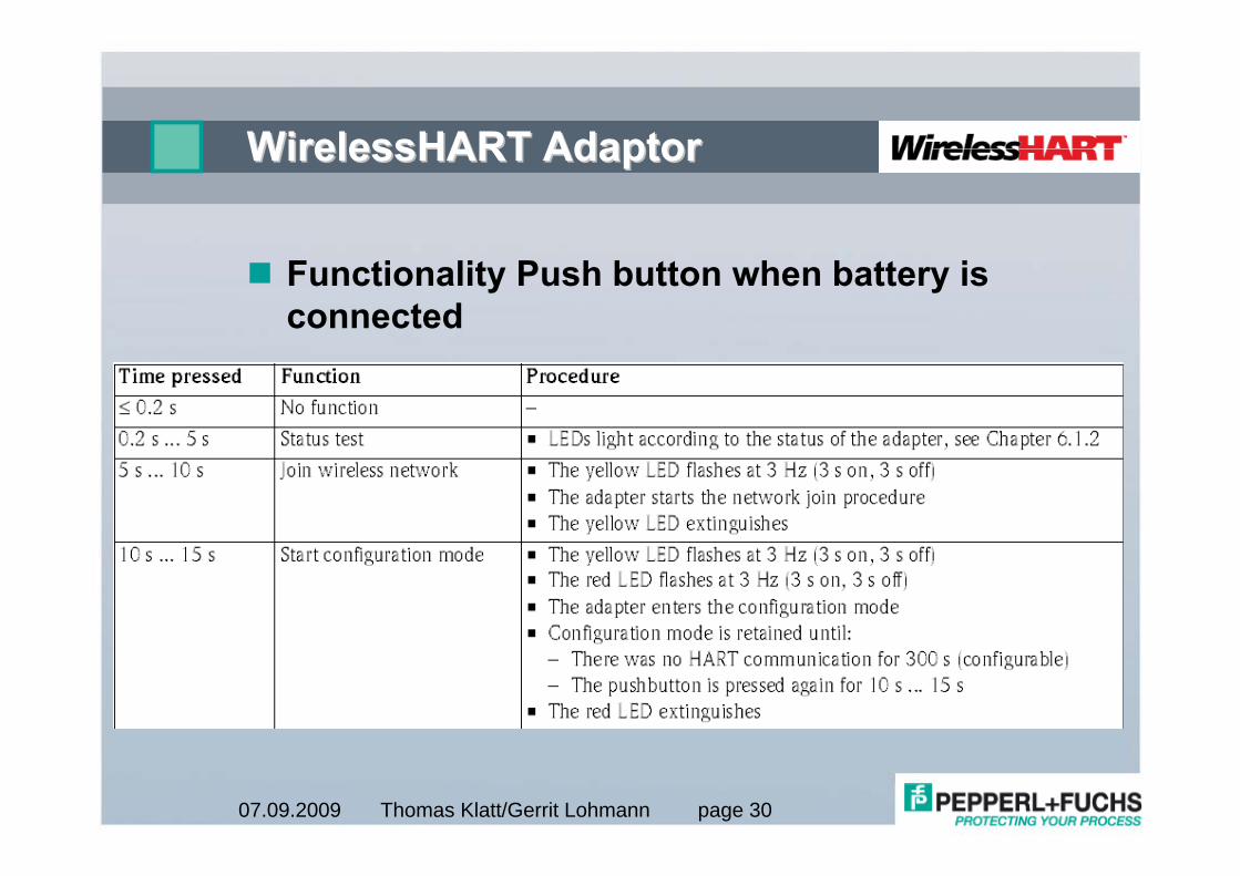
Functionality Push button when battery is connected
Thomas Klatt/Gerrit Lohmann page 3107.09.2009
WirelessHART AdaptorWirelessHART Adaptor
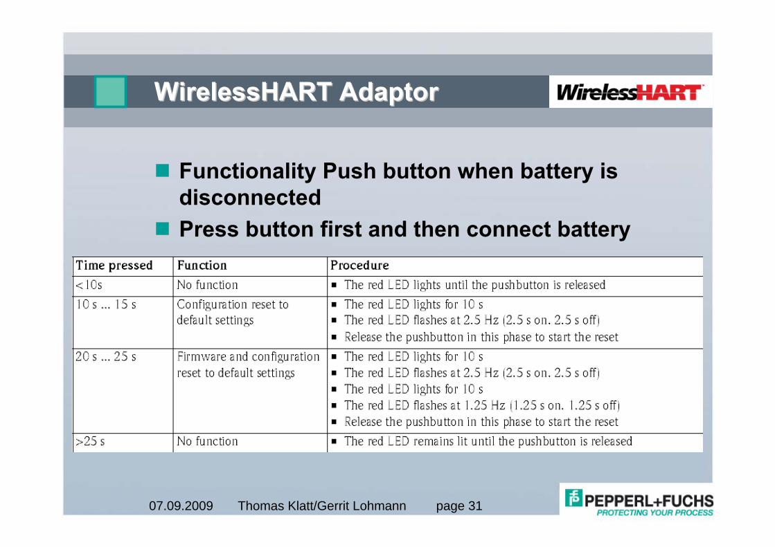
Functionality Push button when battery is disconnectedPress button first and then connect battery
Thomas Klatt/Gerrit Lohmann page 3207.09.2009
WirelessHART AdaptorWirelessHART Adaptor
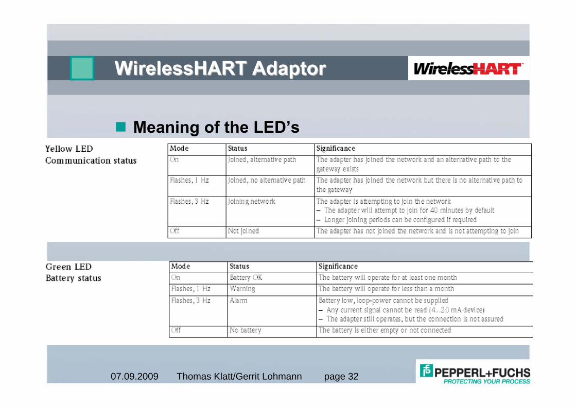
Meaning of the LED’s
Thomas Klatt/Gerrit Lohmann page 3307.09.2009
WirelessHART AdaptorWirelessHART Adaptor
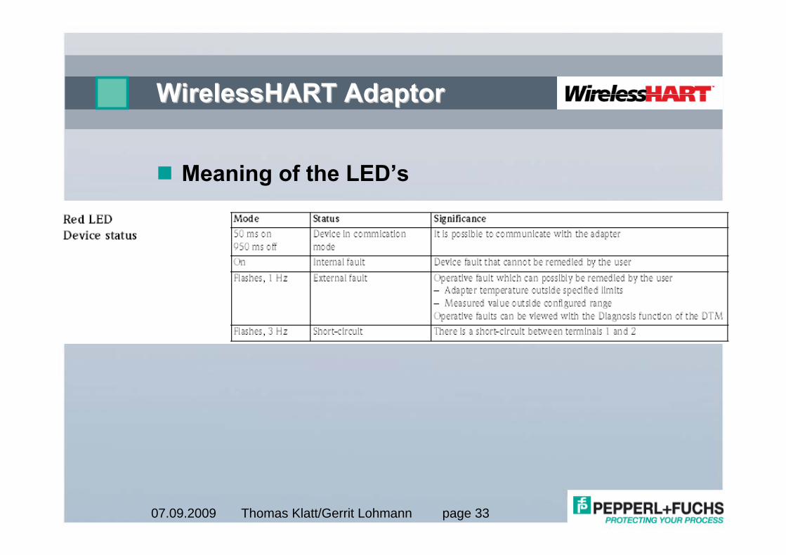
Meaning of the LED’s
Thomas Klatt/Gerrit Lohmann page 3407.09.2009
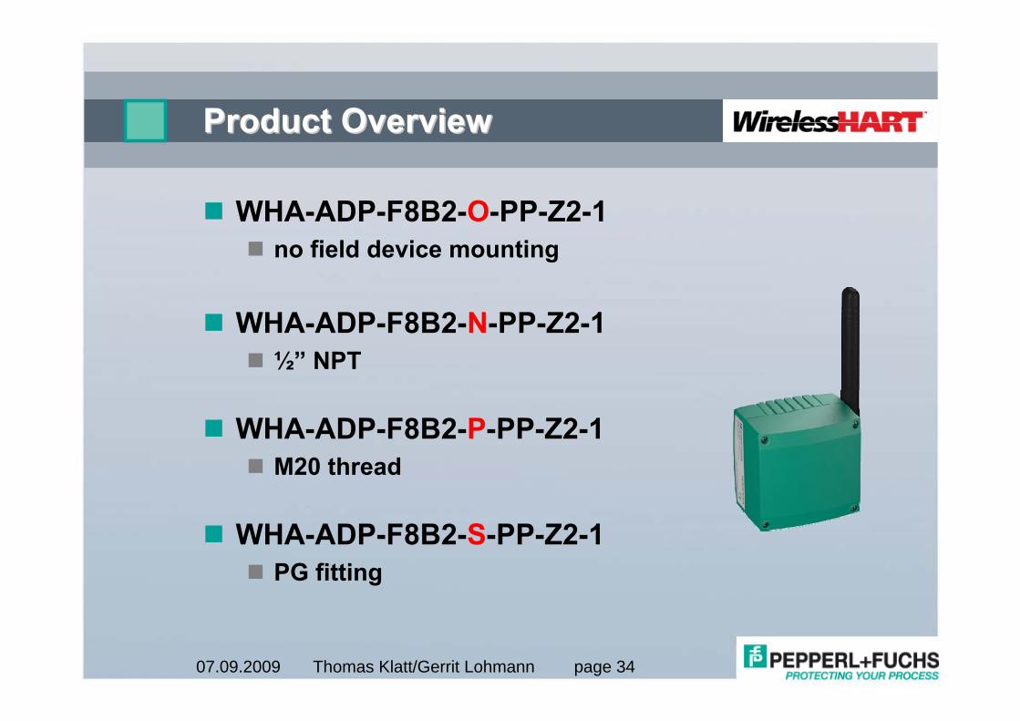
Product OverviewProduct Overview
WHA-ADP-F8B2-O-PP-Z2-1no field device mounting
WHA-ADP-F8B2-N-PP-Z2-1½” NPT
WHA-ADP-F8B2-P-PP-Z2-1M20 thread
WHA-ADP-F8B2-S-PP-Z2-1PG fitting
Thomas Klatt/Gerrit Lohmann page 3507.09.2009
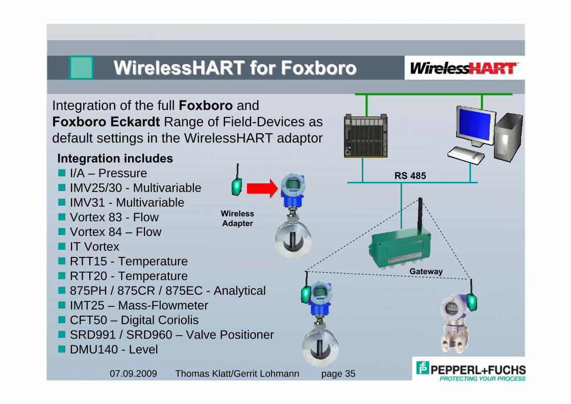
WirelessHARTWirelessHART for Foxborofor Foxboro
Integration includes I/A – PressureIMV25/30 - MultivariableIMV31 - MultivariableVortex 83 - Flow Vortex 84 – FlowIT VortexRTT15 - TemperatureRTT20 - Temperature875PH / 875CR / 875EC - AnalyticalIMT25 – Mass-FlowmeterCFT50 – Digital CoriolisSRD991 / SRD960 – Valve PositionerDMU140 - Level
RS 485
Integration of the full Foxboro and Foxboro Eckardt Range of Field-Devices as default settings in the WirelessHART adaptor
WirelessAdapter
Gateway
Thomas Klatt/Gerrit Lohmann page 3607.09.2009
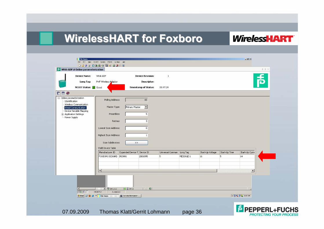
WirelessHARTWirelessHART for Foxborofor Foxboro
Thomas Klatt/Gerrit Lohmann page 3707.09.2009
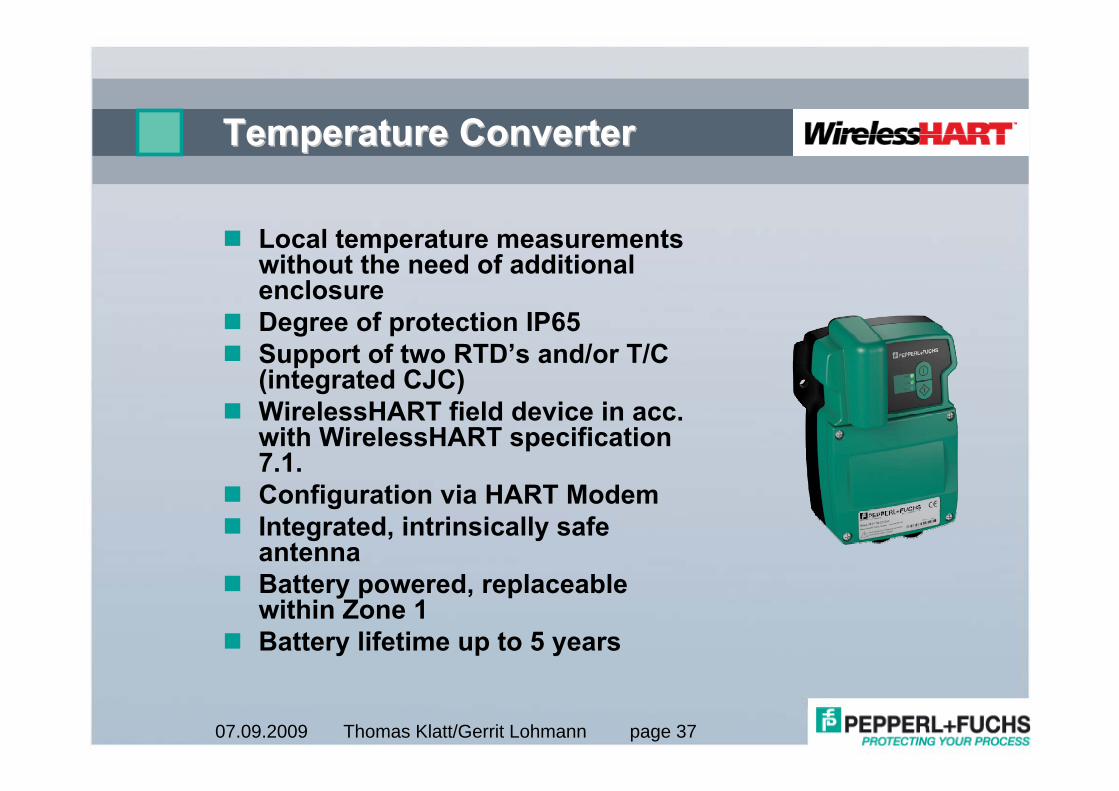
Temperature ConverterTemperature Converter
Local temperature measurements without the need of additional enclosureDegree of protection IP65Support of two RTD’s and/or T/C (integrated CJC)WirelessHART field device in acc. with WirelessHART specification 7.1.Configuration via HART ModemIntegrated, intrinsically safe antennaBattery powered, replaceable within Zone 1Battery lifetime up to 5 years
Thomas Klatt/Gerrit Lohmann page 3807.09.2009
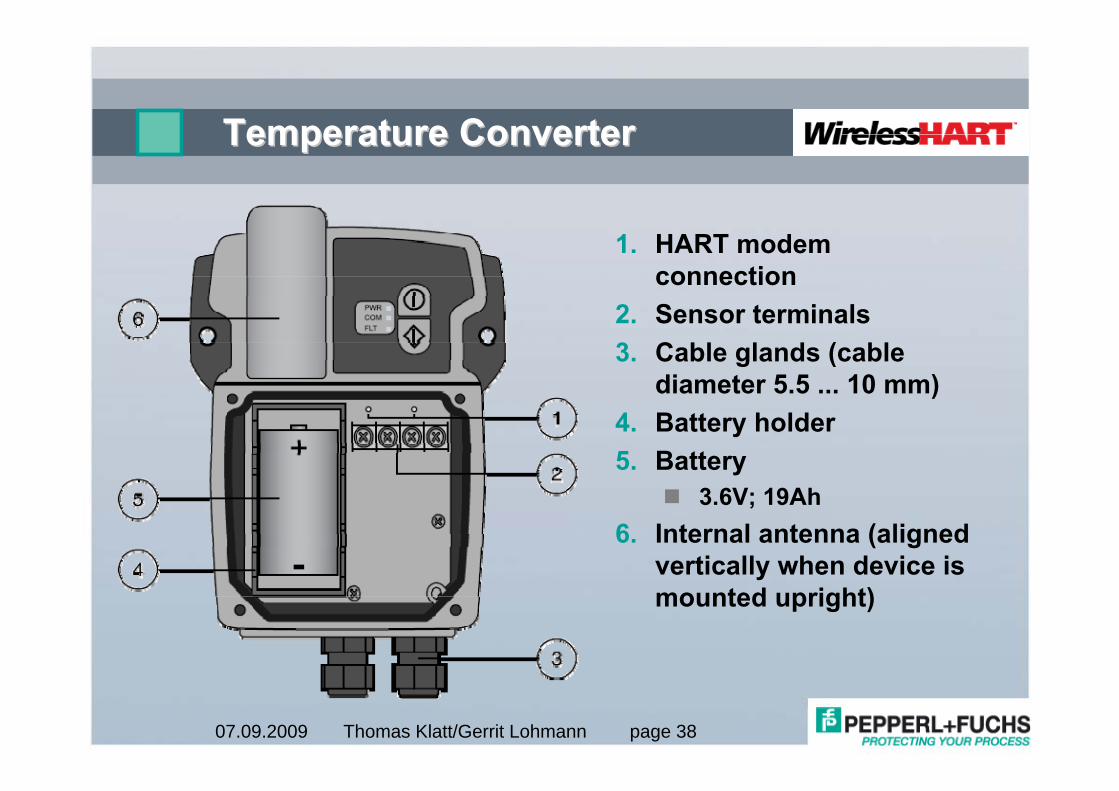
Temperature ConverterTemperature Converter
1. HART modem connection
2. Sensor terminals3. Cable glands (cable
diameter 5.5 ... 10 mm)4. Battery holder5. Battery
3.6V; 19Ah6. Internal antenna (aligned
vertically when device is mounted upright)
Thomas Klatt/Gerrit Lohmann page 3907.09.2009
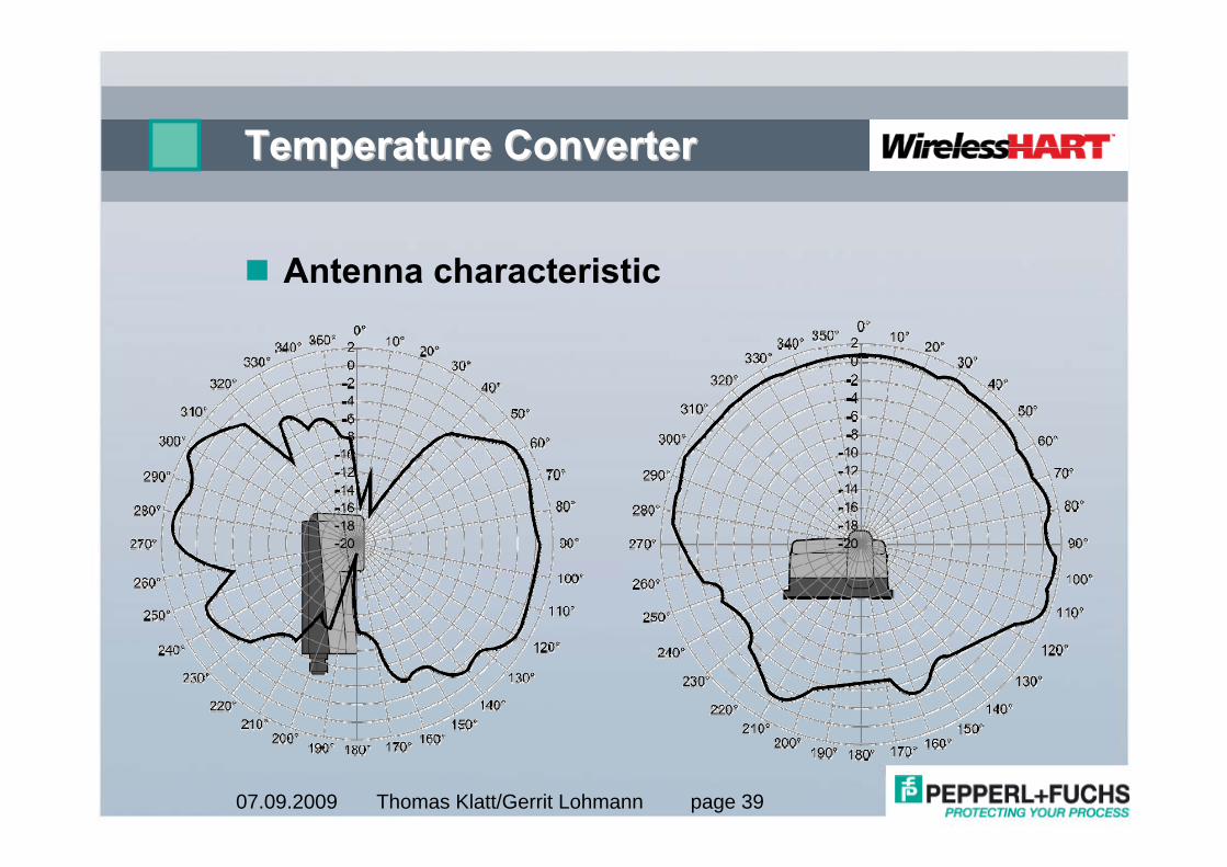
Temperature ConverterTemperature Converter
Antenna characteristic
Thomas Klatt/Gerrit Lohmann page 4007.09.2009
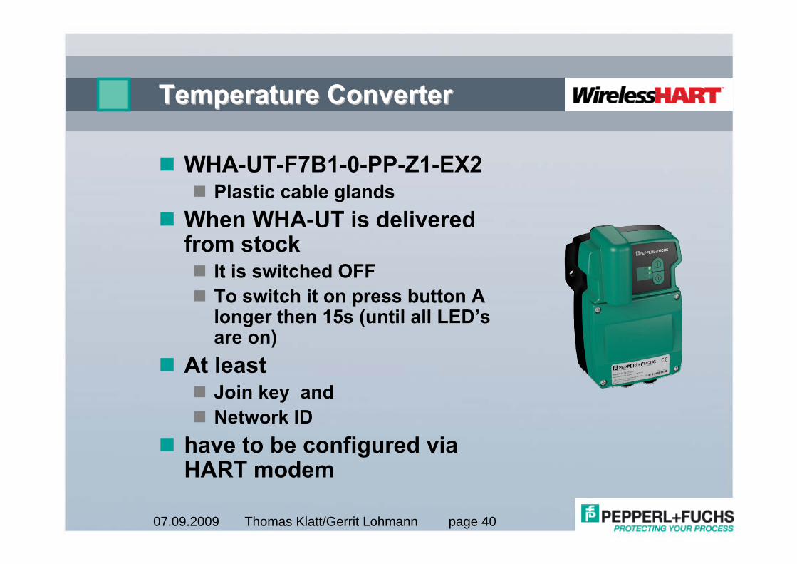
Temperature ConverterTemperature Converter
WHA-UT-F7B1-0-PP-Z1-EX2Plastic cable glands
When WHA-UT is delivered from stock
It is switched OFFTo switch it on press button A longer then 15s (until all LED’s are on)
At leastJoin key andNetwork ID
have to be configured via HART modem
Thomas Klatt/Gerrit Lohmann page 4107.09.2009
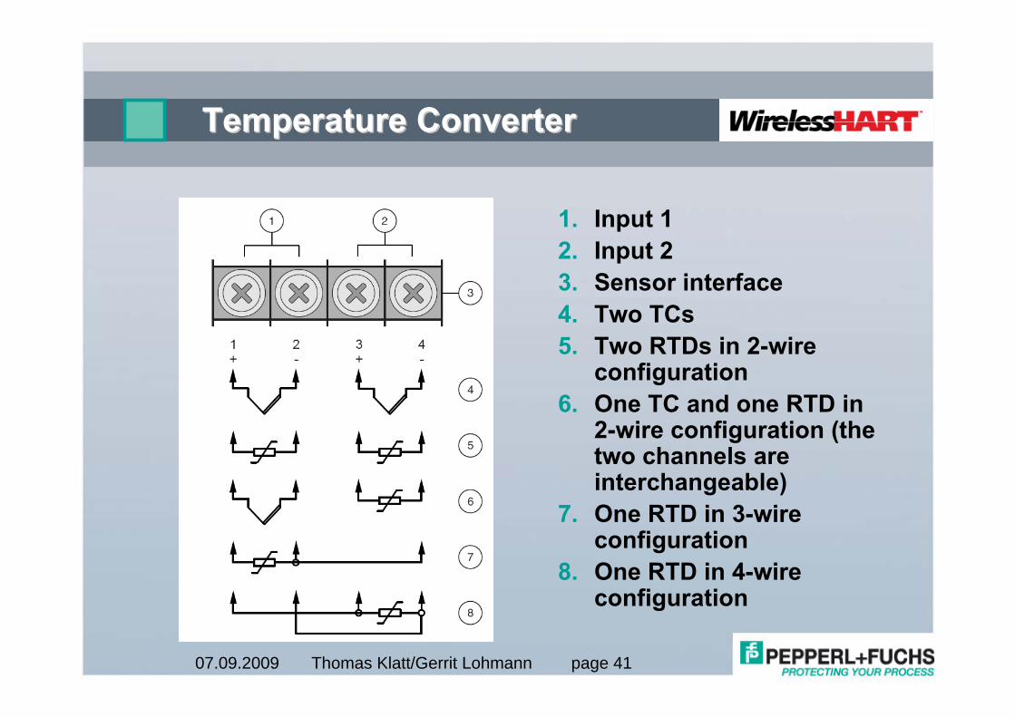
Temperature ConverterTemperature Converter
1. Input 12. Input 23. Sensor interface4. Two TCs5. Two RTDs in 2-wire
configuration6. One TC and one RTD in
2-wire configuration (the two channels are interchangeable)
7. One RTD in 3-wire configuration
8. One RTD in 4-wire configuration
Thomas Klatt/Gerrit Lohmann page 4207.09.2009
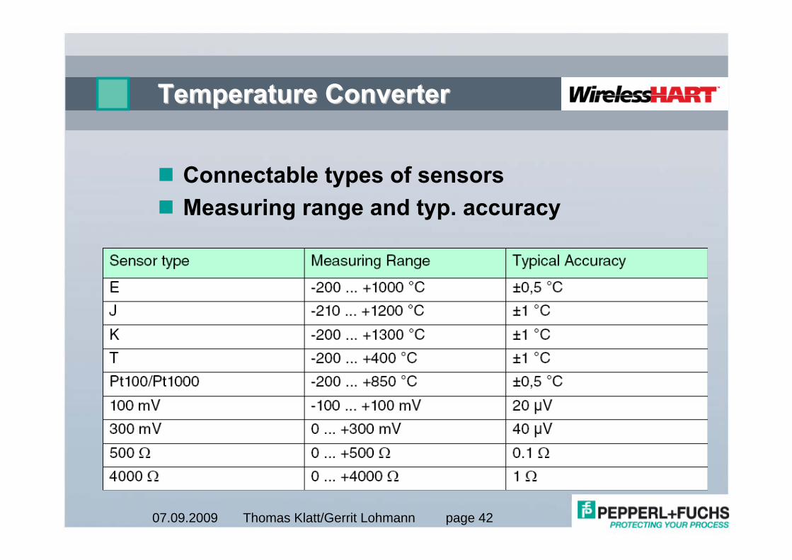
Temperature ConverterTemperature Converter
Connectable types of sensorsMeasuring range and typ. accuracy

Thomas Klatt/Gerrit Lohmann page 4307.09.2009

Thomas Klatt/Gerrit Lohmann page 4407.09.2009
PROTECTING YOUR PROCESSPROTECTING YOUR PROCESS