kathrein-werke kg. our customers are invited to benefit … · kathrein’s quality ... 724 347 127...
TRANSCRIPT


“Quality leads the way“ is our company motto - and this best describes the product philosophy ofKATHREIN-Werke KG.
Kathrein’s quality assurance system is certified inaccordance with ISO 9001. It covers not only deve-lopment, production and marketing, but also otherareas, such as administration and the correct deli-very of products to our customers.
Our customers are invited to benefit fromKathrein’s expertise and to discuss any specialrequirements with us.
Use our know-how!
Quality leads the way
ISO 9001 Certificate
Target Groups:This catalogue is aimed at • System suppliers of mobile communication networks • Manufacturers of mobile radio equipment• Operators of various mobile communication networks• Authorities and organisations concerned with safety issues• Community offices, authorities, organisations and private companies
Edition 2005
Internet: http://www.kathrein.de
KATHREIN-Werke KG . Phone +49 8031 184-0 . Fax +49 8031 184-494Anton-Kathrein-Straße 1 – 3 . P.O. Box 10 04 44 . 83004 Rosenheim . Germany
Antennen . Electronic

Active Multicouplers68 – 87.5 MHz146 – 174 MHz380 – 470 MHz
System Components
Multiband Combiners andTransmitter Combiners
Filter Transmitter CombinersHybrid Transmitter Combiners
Multiband Combiners
Duplexers68 ... 87.5 MHz146 ... 174 MHz380 ... 470 MHz
Filters68 – 87.5 MHz146 – 174 MHz380 – 470 MHz
Combiner Systems
3
3-dB Couplers4.7-dB, 6-dB, 7-dB, 10-dB Couplers
Hybrid Ring JunctionsDecoupled Power Splitters
CirculatorsDC-Stops
Attenuators50-Ω Loads

Summary of TypesThe articles are listed by type number in numerical order
Type No. Page Type No. Page Type No. Page Type No. Page
717 401 125718 290 82718 313 84718 388 72718 500 108718 987 64719 035 108719 069 64719 084 66719 090 125719 237 84719 628 72719 782 131719 785 82719 792 108720 209 66720 296 119720 297 131720 298 125720 642 74720 877 74720 938 119720 942 131721 000 119721 060 125721 062 123721 138 110721 687 20721 751 18721 752 18721 753 18721 754 18721 755 36721 756 36721 757 36721 758 36721 759 52721 760 52721 761 52721 762 52721 767 54721 784 20721 785 38721 786 38722 437 111722 440 111722 488 131722 675 125722 916 38722 917 38723 013 110723 594 54723 790 54724 346 121724 347 127724 348 135724 579 20724 580 20724 581 54725 168 56
725 234 127725 870 121725 871 135726 941 22727 621 150727 622 151728 024 34728 954 111729 870 40730 092 132780 060 129780 232 148780 233 149780 234 146780 235 147782 10189 134782 10231 134782 10361 86782 10362 86782 10363 86782 10364 88782 10365 88782 10366 90782 10367 90782 10369 112782 10370 87, 89, 91782 10371 86782 10372 86782 10373 86782 10374 88782 10375 88782 10376 90782 10377 90782 10380 87, 89, 91 782 10460 113784 10140 104784 10063 106784 10165 104784 10166 104784 10167 104784 10168 104784 10175 136784 10235 138784 10236 138784 10237 138784 10238 138784 10367 140790 044 99790 215 136790 244 110790 589 131790 590 131790 594 99790 957 110790 964 28790 965 28790 966 44790 967 44791 255 80791 374 8
791 463 111791 630 137791 644 106791 646 106791 649 106791 652 106791 730 24791 918 139791 919 139791 920 139791 921 139792 047 8792 059 102792 061 102792 064 102792 067 102792 100 98792 101 98792 102 98792 119 34792 331 131792 777 131792 978 76792 979 76793 097 119793 098 119793 099 119793 100 119793 101 119793 102 125793 103 125793 104 125793 205 98793 206 98793 276 122793 277 128793 297 100793 299 100793 306 100793 308 100793 356 62793 357 70K 60 21 21 A 153K 60 21 21 B 153K 60 21 21 12 A 153K 60 21 21 12 B 153K 60 21 21 14 A 153K 60 21 21 14 B 153K 60 21 21 15 A 153K 60 21 21 15 B 153K 60 21 41 A 152K 60 21 41 B 152K 60 21 41 12 A 152K 60 21 41 12 B 152K 60 21 41 14 A 152K 60 21 41 14 B 152K 60 21 41 15 A 152K 60 21 41 15 B 152K 62 26 11 1 140K 62 26 20 1 141
4
K 62 26 20 7 141K 62 26 21 1 141K 62 26 21 7 141K 62 26 30 1 141K 62 26 30 7 141K 62 26 31 1 141K 62 26 31 7 141K 62 26 40 1 141K 62 26 41 1 141K 62 26 50 1 141K 62 26 50 7 141K 62 26 51 1 141K 62 26 61 1 140K 62 70 21 124K 62 70 27 124K 62 70 41 118K 62 70 47 118K 62 73 21 126K 62 73 41 120K 63 70 21 130K 63 70 27 130K 63 73 21 1 133K 64 00 21 26K 64 12 41 10K 64 13 41 10K 64 21 25 1 30K 64 21 26 1 34K 64 21 45 1 12K 64 21 46 1 16K 64 21 47 1 16K 64 31 21 32K 64 31 27 32K 64 31 41 14K 64 31 47 14K 64 32 21 32K 64 32 27 32K 64 32 41 14K 64 32 47 14K 64 33 21 32K 64 33 27 32K 64 33 41 14K 64 33 47 14K 64 41 23 78K 64 41 24 78K 64 41 43 68K 64 41 44 68K 64 50 4 108K 65 00 21 42K 65 21 25 1 46K 65 21 26 1 50K 65 31 21 48K 65 31 27 48K 65 32 21 48K 65 32 27 48K 65 33 21 48K 65 33 27 48K 65 41 25 92K 65 41 26 92

Filters68 – 87.5 MHz146 – 174 MHz380 – 470 MHz
5
Filt
ers

6

7
3-cavity Band-pass Filter 791 374 74 – 78 MHz 50 W 83-cavity Band-pass Filter 792 047 84 – 88 MHz 50 W 82-cavity Band-pass Filter K 64 12 41 68 ... 87.5 MHz 50 W 103-cavity Band-pass Filter K 64 13 41 68 ... 87.5 MHz 50 W 10Band-pass Filter K 64 21 45 1 68 ... 87.5 MHz 200 W 121-cavity Band-stop Filter K 64 31 41 68 ... 87.5 MHz 300 W 141-cavity Band-stop Filter K 64 31 47 68 ... 87.5 MHz 300 W 142-cavity Band-stop Filter K 64 32 41 68 ... 87.5 MHz 300 W 142-cavity Band-stop Filter K 64 32 47 68 ... 87.5 MHz 300 W 143-cavity Band-stop Filter K 64 33 41 68 ... 87.5 MHz 300 W 143-cavity Band-stop Filter K 64 33 47 68 ... 87.5 MHz 300 W 14S-P Filter K 64 21 46 1 68 ... 87.5 MHz 200 W 16S-P Filter K 64 21 47 1 68 ... 87.5 MHz 200 W 16S-P Filter 721 751 68 ... 87.5 MHz 100 W 18S-P Filter 721 752 68 ... 87.5 MHz 100 W 18S-P Filter 721 753 68 ... 87.5 MHz 100 W 18S-P Filter 721 754 68 ... 87.5 MHz 100 W 18S-P Filter 721 784 68 ... 87.5 MHz 100 W 20S-P Filter 721 687 68 ... 87.5 MHz 100 W 20S-P Filter 724 579 68 ... 87.5 MHz 100 W 20S-P Filter 724 580 68 ... 87.5 MHz 100 W 20Low-pass Filter 726 941 68 – 87.5 MHz 40 W 22
3-cavity Band-pass Filter 791 730 150 ... 169 MHz 50 W 242-cavity Band-pass Filter K 64 00 21 146 ... 174 MHz 50 W 262-cavity Band-pass Filter 790 965 146 ... 174 MHz 75 W 283-cavity Band-pass Filter 790 964 146 ... 174 MHz 100 W 28Band-pass Filter K 64 21 25 1 146 ... 174 MHz 200 W 301-cavity Band-stop Filter K 64 31 21 146 ... 174 MHz 300 W 321-cavity Band-stop Filter K 64 31 27 146 ... 174 MHz 300 W 322-cavity Band-stop Filter K 64 32 21 146 ... 174 MHz 300 W 322-cavity Band-stop Filter K 64 32 27 146 ... 174 MHz 300 W 323-cavity Band-stop Filter K 64 33 21 146 ... 174 MHz 300 W 323-cavity Band-stop Filter K 64 33 27 146 ... 174 MHz 300 W 32S-P Filter 792 119 146 ... 174 MHz 15 W 34S-P Filter 728 024 146 ... 174 MHz 200 W 34S-P Filter K 64 21 26 1 146 ... 174 MHz 200 W 34S-P Filter 721 755 146 ... 174 MHz 100 W 36S-P Filter 721 756 146 ... 174 MHz 100 W 36S-P Filter 721 757 146 ... 174 MHz 100 W 36S-P Filter 721 758 146 ... 174 MHz 100 W 36S-P Filter 721 785 146 ... 174 MHz 100 W 38S-P Filter 722 916 146 ... 174 MHz 100 W 38S-P Filter 721 786 146 ... 174 MHz 100 W 38S-P Filter 722 917 146 ... 174 MHz 100 W 38Low-pass Filter 729 870 146 – 174 MHz 40 W 40
2-cavity Band-pass Filter K 65 00 21 380 ... 470 MHz 50 W 422-cavity Band-pass Filter 790 967 380 ... 470 MHz 50 W 443-cavity Band-pass Filter 790 966 380 ... 470 MHz 50 W 44Band-pass Filter K 65 21 25 1 380 ... 470 MHz 200 W 461-cavity Band-stop Filter K 65 31 21 380 ... 470 MHz 300 W 481-cavity Band-stop Filter K 65 31 27 380 ... 470 MHz 300 W 482-cavity Band-stop Filter K 65 32 21 380 ... 470 MHz 300 W 482-cavity Band-stop Filter K 65 32 27 380 ... 470 MHz 300 W 483-cavity Band-stop Filter K 65 33 21 380 ... 470 MHz 300 W 483-cavity Band-stop Filter K 65 33 27 380 ... 470 MHz 300 W 48S-P Filter K 65 21 26 1 380 ... 470 MHz 200 W 50S-P Filter 721 759 380 ... 470 MHz 100 W 52S-P Filter 721 760 380 ... 470 MHz 100 W 52S-P Filter 721 761 380 ... 470 MHz 100 W 52S-P Filter 721 762 380 ... 470 MHz 100 W 52S-P Filter 723 594 380 ... 470 MHz 100 W 54S-P Filter 723 790 380 ... 470 MHz 100 W 54S-P Filter 721 767 380 ... 470 MHz 100 W 54S-P Filter 724 581 380 ... 470 MHz 100 W 54Low-pass Filter 725 168 400 – 470 MHz 50 W 56
Summary of Articles
Filters:
Description Type No. Frequency range Max. input power Page... tunable bandwidth– fixed bandwidth (not tunable)

Type No. 791 374 792 047
8
Band-pass Filter74 ... 88 MHz
The band-pass filter is suitable for use as a receiving or transmitting filter for one orseveral receivers, or one transmitter.
It can be used:– to improve the input selectivity of
receivers and amplifiers,– to increase the isolation of transmitters,
whose respective antennas are mounted close together,
– to suppress noise side bands and intermodulation products,
– as a combiner component.
Design and construction:The band-pass filter consists of threecapacitively coupled helix resonators.
Filter characteristics:Broad pass band with low insertion loss and high stop band attenuation outside ofthe pass band.
Pass band 74 – 78 MHz 84 – 88 MHzInsertion loss < 0.7 dBPass band bandwidth 4.0 MHzVSWR < 1.2 (at pass band)Impedance 50 ΩInput power < 50 WTemperature range –20 … +50 °CConnectors N femaleMaterial Aluminium / copper, silver-platedInstallation With 4 screws (max. 4 mm diameter)Weight 0.9 kgPacking size 188 mm x 80 mm x 153 mmDimensions (w x h x d) 140 mm x 68 mm x 130 mm
(with connectors)
Technical Data
791 374

Band-pass Filter74 ... 88 MHzTypical attenuation curves
9
0
5
10
15
20
25
30
35
40
45
50
50 55 60 65 70 75 80 85 90 95 100
Frequency/MHz
Atte
nuat
ion/
dB791 374
0
5
10
15
20
25
30
35
40
45
50
50 55 60 65 70 75 80 85 90 95 100
Frequency/MHz
Atte
nuat
ion/
dB
792 047
Band-pass Filter68 … 87.5 MHz
10
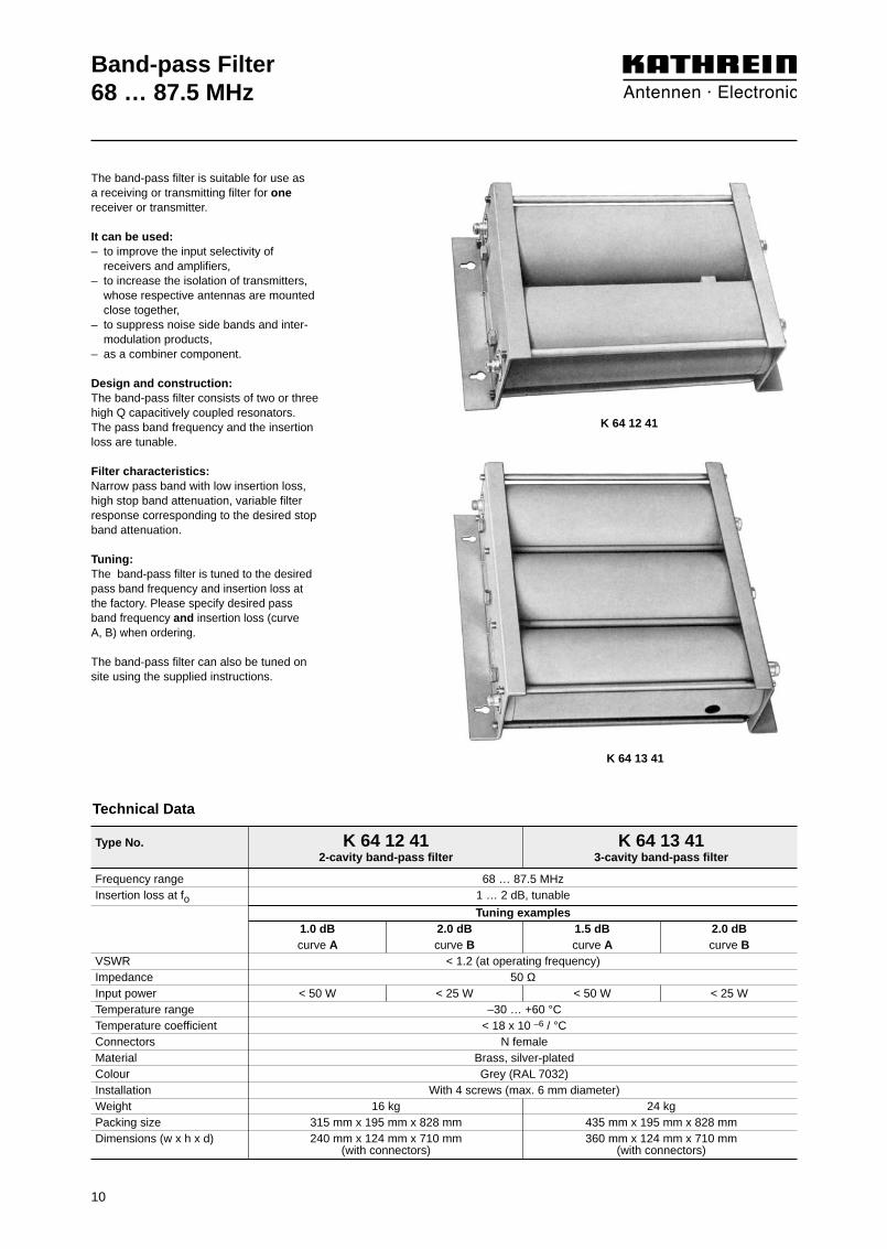
K 64 12 41
K 64 13 41
Type No. K 64 12 41 K 64 13 412-cavity band-pass filter 3-cavity band-pass filter
Frequency range 68 … 87.5 MHzInsertion loss at fo 1 … 2 dB, tunable
Tuning examples1.0 dB 2.0 dB 1.5 dB 2.0 dBcurve A curve B curve A curve B
VSWR < 1.2 (at operating frequency)Impedance 50 ΩInput power < 50 W < 25 W < 50 W < 25 WTemperature range –30 … +60 °CTemperature coefficient < 18 x 10 –6 / °CConnectors N femaleMaterial Brass, silver-platedColour Grey (RAL 7032)Installation With 4 screws (max. 6 mm diameter)Weight 16 kg 24 kgPacking size 315 mm x 195 mm x 828 mm 435 mm x 195 mm x 828 mmDimensions (w x h x d) 240 mm x 124 mm x 710 mm 360 mm x 124 mm x 710 mm
(with connectors) (with connectors)
Technical Data
The band-pass filter is suitable for use as a receiving or transmitting filter for onereceiver or transmitter.
It can be used:– to improve the input selectivity of
receivers and amplifiers,– to increase the isolation of transmitters,
whose respective antennas are mounted close together,
– to suppress noise side bands and inter-modulation products,
– as a combiner component.
Design and construction:The band-pass filter consists of two or threehigh Q capacitively coupled resonators. The pass band frequency and the insertionloss are tunable.
Filter characteristics: Narrow pass band with low insertion loss,high stop band attenuation, variable filterresponse corresponding to the desired stopband attenuation.
Tuning:The band-pass filter is tuned to the desiredpass band frequency and insertion loss atthe factory. Please specify desired passband frequency and insertion loss (curve A, B) when ordering.
The band-pass filter can also be tuned onsite using the supplied instructions.

11
Band-pass Filter68 … 87.5 MHzTypical attenuation curves
0
10
20
30
40
50
60
70
80
90
100
-5 -4 -3 -2 -1 f0 +1 +2 +3 +4 +5
A
B
Frequency/MHz
Atte
nuat
ion/
dB
0
10
20
30
40
50
60
70
80
90
100
-2.5 -2.0 -1.5 -1.0 -0.5 f0 +0.5 +1.0 +1.5 +2.0 +2.5
A
B
Frequency/MHz
Atte
nuat
ion/
dB
0
2
4
6
8
10
12
14
16
18
20
-0.5 -0.4 -0.3 -0.2 -0.1 f0 +0.1 +0.2 +0.3 +0.4 +0.5
A
B
Frequency/MHz
Atte
nuat
ion/
dB
0
10
20
30
40
50
60
70
80
90
100
-5 -4 -3 -2 -1 f0 +1 +2 +3 +4 +5
A
B
Frequency/MHz
Atte
nuat
ion/
dB
0
2
4
6
8
10
12
14
16
18
20
-0.5 -0.4 -0.3 -0.2 -0.1 f0 +0.1 +0.2 +0.3 +0.4 +0.5
A
B
Frequency/MHz
Atte
nuat
ion/
dB
2-cavity band-pass filter K 64 12 41
3-cavity band-pass filterK 64 13 41
Diagram I: Diagram I:
Diagram III: Diagram III:
Diagram II:Diagram II:
Tuning examples:
Detail seediagram II
Detail seediagram II
Detail seediagram III
0
10
20
30
40
50
60
70
80
90
100
-2.5 -2.0 -1.5 -1.0 -0.5 f0 +0.5 +1.0 +1.5 +2.0 +2.5
A
B
Frequency/MHz
Atte
nuat
ion/
dB Detail seediagram III

Type No. K 64 21 45 1
12
Band-pass Filter68 … 87.5 MHz
Frequency range 68 … 87.5 MHzInsertion loss at fo 0.5 … 2 dB, tunable
Tuning examples0.5 dB 1.0 dB 1.5 dB 2.0 dBcurve A curve B curve C curve D
VSWR < 1.5 (at operating frequency)Impedance 50 ΩInput power < 200 WTemperature range –30 … +60 °CEffect of temperature < 0.2 kHz / °CConnectors N femaleMaterial Outer conductor: Aluminium
Inner conductor: Brass, silver-platedInstallation Free standing or wall mounting
with mounting anglesAttached hardware Band-pass filter with 2 mounting angles
and 2 connecting piecesWeight 16 kgPacking size 207 mm x 1660 mm x 207 mmDimensions (w x h x d) 190 mm x max. 1500 mm x 190 mm
(with tuning rod)
Technical Data
The band-pass filter is suitable for use as a receiving or transmitting filter for onereceiver or transmitter.
It can be used:– to improve the input selectivity of
receivers and amplifiers,– to increase the isolation of transmitters,
whose respective antennas are mounted close together,
– to suppress noise side bands and inter-modulation products,
– as a combiner component.
Design and construction:The band-pass filter is designed as a tem-perature stabilized λ/4 coaxial resonator.The pass band frequency and the insertionloss are tunable.
Filter characteristics: Narrow pass band with low insertion loss,high stop band attenuation, variable filterresponse corresponding to the desired stopband attenuation.
Combination of several band-pass filters:Several band-pass filters can be intercon-nected using cables of an electrical lengthof λ/4. This causes an increase in the edgesteepness of the filter curve as well as thebandwidth of the pass band. The individualfilters are tuned to the center frequency ofthe complete filter.
Insertion loss of the filter combination = Sum insertion loss of the individual filters +cable attenuation of the interconnectingcables (about 0.1 dB per cable). Stop band attenuation of the filter combina-tion = Sum stop band attenuation of individ-ual filters + additional stop band attenuation.
If the stop band attenuation of the individualfilters exceeds 10 dB, approximately the following applies: additional stop band attenuation = (n – 1) x 5 dB;n = number of individual filters.For special applications band-pass filterscan also be interconnected with S-P filters.
Tuning:The band-pass filter is tuned to the desiredpass band frequency and insertion loss atthe factory. Please specify desired pass bandfrequency and insertion loss (curve A, B, C,D) when ordering.
The band-pass filter can also be tuned onsite using the supplied instructions.
K 64 21 45 1

0
5
10
15
20
25
30
35
40
45
50
-1.25 -1.0 -0.75 -0.50 -0.25 f0 +0.25 +0.50 +0.75 +1.00 +1.25
Frequency/MHz
Atte
nuat
ion/
dB
A
B
C
D
13
Band-pass Filter68 … 87.5 MHzTypical attenuation curves
0
5
10
15
20
25
30
35
40
45
50
-5 -4 -3 -2 -1 f0 +1 +2 +3 +4 +5
Frequency/MHz
Atte
nuat
ion/
dB
A
B
C
D
0
1
2
3
4
5
6
7
8
9
10
-0.25 -0.20 -0.15 -0.10 -0.05 f0 +0.05 +0.10 +0.15 +0.20 +0.25
Frequency/MHz
Atte
nuat
ion/
dB
A
BCD
Diagram I:
Diagram III:
Diagram II:
Detail seediagram II
Detail seediagram III
Tuning examples:

14
Band-stop Filter68 … 87.5 MHz
Technical Data
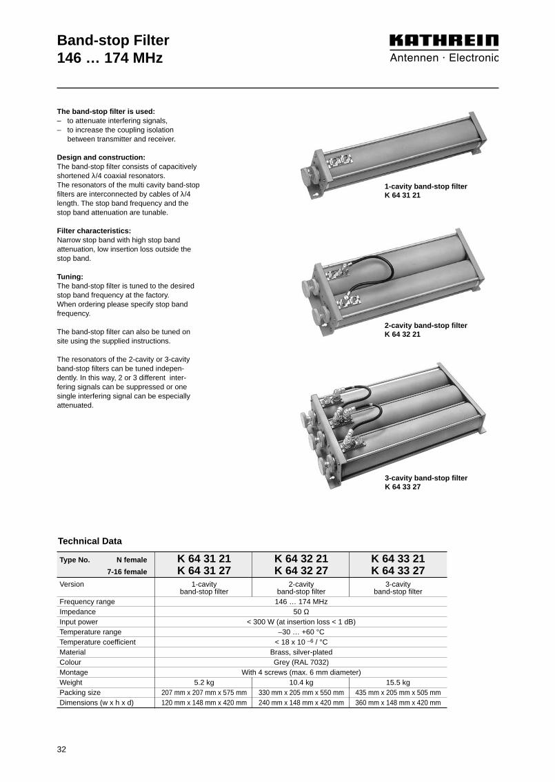
The band-stop filter is used:– to attenuate interfering signals,– to increase the isolation between trans-
mitter and receiver.
Design and construction:The band-stop filter consists of capacitivelyshortened λ/4 coaxial resonators. The res-onators of the multi cavity band-stop filtersare interconnected by cables of λ/4 length.The stop band frequency and the stop bandattenuation are tunable.
Filter characteristics: Narrow stop band with high stop bandattenuation, low insertion loss outside of the stop band.
Tuning:The band-stop filter is tuned to the desiredstop band frequency at the factory. When ordering please specify stop bandfrequency.
The band-stop filter can also be tuned onsite using the supplied instructions.
The resonators of the 2-cavity or 3-cavityband-stop filters can be tuned indepen-dently. In this way, 2 or 3 different inter-fering signals can be suppressed or onesingle interfering signal can be especially attenuated.
Type No. N female K 64 31 41 K 64 32 41 K 64 33 417-16 female K 64 31 47 K 64 32 47 K 64 33 47
Version 1-cavity 2-cavity 3-cavityband-stop filter band-stop filter band-stop filter
Frequency range 68 … 87.5 MHz Impedance 50 ΩInput power < 300 W (at insertion loss < 1 dB)Temperature range –30 … +60 °CTemperature coefficient < 18 x 10 –6 / °CMaterial Brass, silver-platedColour Grey (RAL 7032)Installation With 4 screws (max. 6 mm diameter)Weight 8.3 kg 16.6 kg 25.0 kgPacking size 207 mm x 207 mm x 865 mm 285 mm x 210 mm x 840 mm 445 mm x 210 mm x 840 mmDimensions (w x h x d) 120 mm x 148 mm x 710 mm 240 mm x 148 mm x 710 mm 360 mm x 148 mm x 710 mm
1-cavity band-stop filterK 64 31 41
2-cavity band-stop filterK 64 32 41
3-cavity band-stop filterK 64 33 47

15
Band-stop Filter68 … 87.5 MHzTypical attenuation curves
1-cavity band-stop filter
2-cavity band-stop filter
3-cavity band-stop filter
0
10
20
30
40
50
60
70
80
90
100
-1.25 -1.0 -0.75 -0.50 -0.25 f0 +0.25 +0.50 +0.75 +1.00 +1.25
Atte
nuat
ion/
dB
Frequency/MHz
0
10
20
30
40
50
60
70
80
90
100
-1.25 -1.0 -0.75 -0.50 -0.25 f0 +0.25 +0.50 +0.75 +1.00 +1.25
Atte
nuat
ion/
dB
Frequency/MHz
0
0.5
1.0
1.5
2.0
2.5
3.0
3.5
4.0
4.5
5.0
-1.25 -1.0 -0.75 -0.50 -0.25 f0 +0.25 +0.50 +0.75 +1.00 +1.25
Atte
nuat
ion/
dB
Frequency/MHz
0
10
20
30
40
50
60
70
80
90
100
-1.25 -1.0 -0.75 -0.50 -0.25 f0 +0.25 +0.50 +0.70 +1.00 +1.25
Atte
nuat
ion/
dB
Frequency/MHz
0
0.5
1.0
1.5
2.0
2.5
3.0
3.5
4.0
4.5
5.0
-1.25 -1.0 -0.75 -0.50 -0.25 f0 +0.25 +0.50 +0.75 +1.00 +1.25
Atte
nuat
ion/
dB
Frequency/MHz
0
0.5
1.0
1.5
2.0
2.5
3.0
3.5
4.0
4.5
5.0
Atte
nuat
ion/
dBFrequency/MHz
-1.25 -1.0 -0.75 -0.50 -0.25 f0 +0.25 +0.50 +0.75 +1.00 +1.25
Diagram I:
Diagram I:
Diagram I:
Detail seediagram II
Detail seediagram II
Diagram II:
Diagram II:
Diagram II:
Detail seediagram II
Tuning examples:

0.4 0.6 0.8 1.0 1.2 1.4 1.6 1.8 2.0 2.2 2.4
0.4 0.6 0.8 1.0 1.2 1.4 1.6 1.8 2.0 2.2 2.4 0.2
0.2
88
83
78
73
68
88
83
78
73
68
Adjustable frequency separation/MHz
Pas
s ba
nd fr
eque
ncy/
MH
z
Adjustable frequency separation/MHz
Pas
s ba
nd fr
eque
ncy/
MH
z
Technical Data
The S-P filter (Stop-Pass filter) is used toattenuate interfering signals located extre-mely close to the operational frequency.
It can be used:– in the transmission path to suppress
side band noise and to attenuate inter-modulation products at the receiving frequencies,
– in the receiving path to attenuate trans-mitting frequencies,
– as a component for combiners with very low frequency spacing.
Design and construction:The S-P filter is designed as a high Q tem-perature stabilized λ/4 coaxial resonator.Using a special temperature stabilized coupling, high stop band attenuation can be adjusted very close to the pass bandfrequency.
Filter characteristics: Narrow pass band with low insertion loss,high stop band attenuation at the stopband frequency. Even in case of very smallspacing between the pass band and thestop band frequency a high stop bandattenuation is achieved, which can not beachieved using standard band-pass filtersof the same size.
Combination of several S-P filters:Several S-P filters can be interconnected by cables with an electrical length of λ/4.
Insertion loss of the filter combination = Sum insertion loss of the individual filters + cable attenuation of the interconnectingcables (about 0.1 dB per cable). Stop bandattenuation of the filter combination = Sum stop band attenuation of the individualfilters + additional stop band attenuation.
If the stop band attenuation of the individualfilters exceeds 10 dB, approximately the following applies:additional stop band attenuation =(n – 1) x 5 dB;n = number of individual filters.For special applications S-P filters can alsobe interconnected with band-pass filters.
Tuning:The S-P filter is tuned to the desired passband and stop band frequency at the factory. Please specify desired pass bandand stop band frequency when ordering.
The S-P filter can also be tuned on siteusing the supplied instructions.
Customized versionsFor special applications S-P filters for evenlower frequency spacing or lower insertionloss are available.
S-P Filter68 … 87.5 MHz
16
K 64 21 46 1K 64 21 47 1
Pass band frequencyabove the stop band frequency
K 64 21 46 1
K 64 21 47 1
Pass band frequencybelow the stop band frequency
Type No. K 64 21 46 1 K 64 21 47 1
Frequency range 68 … 87.5 MHz Insertion loss 0.5 ±0.15 dBVSWR < 1.5 (at operating frequency)Impedance 50 ΩInput power < 200 WTemperature range –20 … +60 °CEffect of temperature < 0.2 kHz / °CConnectors N femaleMaterial Outer conductor: Aluminium
Inner conductor: Brass, silver-platedInstallation Free standing or wall mountingAttached hardware S-P filter with 2 mounting angles
and 2 connecting piecesWeight 16 kgPacking size 210 mm x 1660 mm x 210 mmDimensions (w x h x d) 190 mm x max. 1500 mm x 190 mm
(with tuning rod)

Frequency/MHz
Atte
nuat
ion/
dB
0
5
10
15
20
25
30
35
40
45
50
A
B
C
D
F
A
B
C
DEF
-0.5 fo +0.5 +1 +1.5
E
E
-1.5 -1 -0.5 fo +0.5
A
B
C
DEF
Frequency/MHz
Atte
nuat
ion/
dB
0
5
10
15
20
25
30
35
40
45
50
A
B
C
D
F
17
S-P Filter68 … 87.5 MHzTypical attenuation curves
Curve Frequency spacingpass band frequency / stop band frequency
A 0.25 MHzB 0.50 MHzC 0.75 MHzD 1.00 MHzE 1.25 MHzF 1.50 MHz
Tuning examples:
K 64 21 46 1
K 64 21 47 1
S-P Filter68 … 87.5 MHz
18
Technical Data
The S-P filter (Stop-Pass filter) is suitable forattenuating interfering frequencies, close to theoperational frequency band. It is designed foroperation with one transmitter respectively withone or several receivers.
It can be used:– in the transmission path for suppressing side
band noise and for attenuating intermodulationproducts at the receiving frequencies,
– in the receiving path for attenuating transmittingfrequencies,
– as a duplexer component.
Design and construction:The S-P filter consists of three or four S-Presonators, interconnected by cables of definedelectrical length.
Filter characteristics:721 751 / 721 752: Broad pass band with low insertion loss in the low band, high stop bandattenuation at the stop band frequencies in thehigh band.721 753 / 721 754: Broad pass band with low insertion loss in the high band, high stop bandattenuation at the stop band frequencies in thelow band.
Tuning:The S-P filter can only be tuned at the factorybecause of its special design. Special requestssuch as: Special band spacing, switching band-widths or attenuation can be taken into account.When ordering please specify the desired highand low band frequencies.
Type No. 721 751 (Pass band: Low band; Stop band: High band) 721 752 (Pass band: Low band; Stop band: High band)
721 753 (Pass band: High band; Stop band: Low band) 721 754 (Pass band: High band; Stop band: Low band)
Number of resonators 3 4Frequency range 68 … 87.5 MHz
Tuning examplesBand spacing 3 MHz 6 MHz 9.8 MHz 2 MHz 6 MHz 9.8 MHzSwitching bandwidth 0.1 MHz 0.5 MHz 1.0 MHz 1.5 MHz 2.5 MHz 0.1 MHz 1.0 MHz 2.5 MHz 3.3 MHz 4.0 MHzInsertion loss < 1.2 dB < 0.6 dB < 0.6 dB < 0.6 dB < 0.8 dB < 1.5 dB < 0.8 dB < 0.8 dB < 0.8 dB < 1.2 dBStop band attenuation > 60 dB > 65 dB > 70 dB > 65 dB > 60 dB > 60 dB > 70 dB > 75 dB > 65 dB > 60 dBVSWR < 1.4 (at operating frequency)Impedance 50 ΩInput power < 100 W (–30 … +55 °C) / < 50 W (+55 … +70 °C)Temperature range –30 … +70 °CConnectors N femaleMaterial S-P resonators: Aluminium / copper, silver-plated; cable: RG 223/UInstallation With 4 screws (max. 4 mm diameter)Weight 1.0 kg 1.2 kgPacking size 235 mm x 61 mm x 165 mmDimensions (w x h x d) 155 mm x 50 mm x 160 mm 195 mm x 50 mm x 160 mm
(with connectors) (with connectors)
721 751721 753
721 752721 754

S-P Filter68 … 87.5 MHzTypical attenuation curves
19
721 751 / 721 753 721 752 / 721 754Band spacing: 6.0 MHz
Switching bandwidth: 0.5 MHzBand spacing: 6.0 MHz
Switching bandwidth: 1.0 MHz
Band spacing: 9.8 MHzSwitching bandwidth: 1.0 MHz
Band spacing: 9.8 MHzSwitching bandwidth: 2.5 MHz
Band spacing: 9.8 MHzSwitching bandwidth: 2.5 MHz
Band spacing: 9.8 MHzSwitching bandwidth: 4.0 MHz
Tuning examples:
0
10
20
30
40
50
60
70
80
90
100
68 70 72 74 76 78 80 82 84 86 88
Frequency/MHz
Atte
nuat
ion/
dB
0
10
20
30
40
50
60
70
80
90
100
68 70 72 74 76 78 80 82 84 86 88
Frequency/MHz
Atte
nuat
ion/
dB
0
10
20
30
40
50
60
70
80
90
100
68 70 72 74 76 78 80 82 84 86 88
Frequency/MHz
Atte
nuat
ion/
dB
0
10
20
30
40
50
60
70
80
90
100
68 70 72 74 76 78 80 82 84 86 88
Frequency/MHz
Atte
nuat
ion/
dB
0
10
20
30
40
50
60
70
80
90
100
68 70 72 74 76 78 80 82 84 86 88
Frequency/MHz
Atte
nuat
ion/
dB
721 752 721 754
721 752 721 754
721 752 721 754
721 753721 751
721 753721 751
0
10
20
30
40
50
60
70
80
90
100
68 70 72 74 76 78 80 82 84 86 88
Frequency/MHz
Atte
nuat
ion/
dB
721 753721 751

S-P Filter68 … 87.5 MHz
20
Technical Data
The S-P filter (Stop-Pass filter) is suitable forattenuating interfering frequencies, close to theoperational frequency band. It is designed foroperation with one or several transmitters respectively with one or several receivers.
It can be used:– in the transmission path for suppressing side
band noise and for attenuating intermodulationproducts at the receiving frequencies,
– in the receiving path for attenuating transmittingfrequencies,
– as a duplexer component.
Design and construction:The S-P filter consists of three or four S-Presonators, interconnected by cables of definedelectrical length.
Filter characteristics:721 784 / 724 579: Broad pass band with low insertion loss in the low band, high stop bandattenuation at the stop band frequencies in thehigh band.721 687 / 724 580: Broad pass band with low insertion loss in the high band, high stop bandattenuation at the stop band frequencies in thelow band.
Tuning:The S-P filter can only be tuned at the factorybecause of its special design. Special requestssuch as: Special band spacing, switching band-widths or attenuation can be taken into account.When ordering please specify the desired highand low band frequencies.
Type No. 721 784 (Pass band: Low band; Stop band: High band) 724 579 (Pass band: Low band; Stop band: High band)
721 687 (Pass band: High band; Stop band: Low band) 724 580 (Pass band: High band; Stop band: Low band)
Number of resonators 3 4Frequency range 68 … 87.5 MHz
Tuning examplesBand spacing 3 MHz 6 MHz 9.8 MHz 2 MHz 6 MHz 9.8 MHzSwitching bandwidth 0.1 MHz 0.5 MHz 1.0 MHz 1.5 MHz 2.5 MHz 0.1 MHz 1.0 MHz 2.5 MHz 3.3 MHz 4.0 MHzInsertion loss < 1.2 dB < 0.6 dB < 0.6 dB < 0.6 dB < 0.8 dB < 1.5 dB < 0.8 dB < 0.8 dB < 0.8 dB < 1.2 dBStop band attenuation > 60 dB > 65 dB > 70 dB > 65 dB > 60 dB > 60 dB > 70 dB > 75 dB > 65 dB > 60 dBVSWR < 1.4 (at operating frequency)Impedance 50 ΩInput power < 100 W (–30 … +55 °C) / < 50 W (+55 … +70 °C)Temperature range –30 … +70 °CConnectors N female, silver-platedMaterial S-P resonators: Brass, silver-plated / copper, silver-plated; cable: RG 223/UInstallation With 4 screws (max. 4 mm diameter)Weight 1.5 kg 1.75 kgPacking size 245 mm x 71 mm x 210 mmDimensions (w x h x d) 155 mm x 60 mm x 175 mm 195 mm x 60 mm x 175 mm
(with connectors) (with connectors)
721 784721 687
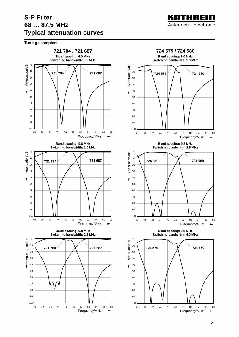
S-P Filter68 … 87.5 MHzTypical attenuation curves
21
721 784 / 721 687 724 579 / 724 580Band spacing: 6.0 MHz
Switching bandwidth: 0.5 MHzBand spacing: 6.0 MHz
Switching bandwidth: 1.0 MHz
Band spacing: 9.8 MHzSwitching bandwidth: 1.0 MHz
Band spacing: 9.8 MHzSwitching bandwidth: 2.5 MHz
Band spacing: 9.8 MHzSwitching bandwidth: 2.5 MHz
Band spacing: 9.8 MHzSwitching bandwidth: 4.0 MHz
Tuning examples:
0
10
20
30
40
50
60
70
80
90
100
68 70 72 74 76 78 80 82 84 86 88
Frequency/MHz
Atte
nuat
ion/
dB
0
10
20
30
40
50
60
70
80
90
100
68 70 72 74 76 78 80 82 84 86 88
Frequency/MHz
Atte
nuat
ion/
dB
0
10
20
30
40
50
60
70
80
90
100
68 70 72 74 76 78 80 82 84 86 88
Frequency/MHz
Atte
nuat
ion/
dB
0
10
20
30
40
50
60
70
80
90
100
68 70 72 74 76 78 80 82 84 86 88
Frequency/MHz
Atte
nuat
ion/
dB
721 687721 784
724 580724 579
724 580724 579
724 580724 579
0
10
20
30
40
50
60
70
80
90
100
68 70 72 74 76 78 80 82 84 86 88
Frequency/MHz
Atte
nuat
ion/
dB
0
10
20
30
40
50
60
70
80
90
100
68 70 72 74 76 78 80 82 84 86 88
Frequency/MHz
Atte
nuat
ion/
dB
721 687721 784
721 687721 784
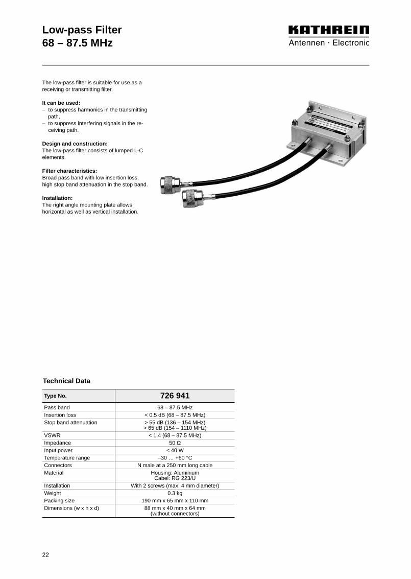
Pass band 68 – 87.5 MHzInsertion loss < 0.5 dB (68 – 87.5 MHz)Stop band attenuation > 55 dB (136 – 154 MHz)
> 65 dB (154 – 1110 MHz)VSWR < 1.4 (68 – 87.5 MHz)Impedance 50 ΩInput power < 40 WTemperature range –30 … +60 °CConnectors N male at a 250 mm long cableMaterial Housing: Aluminium
Cabel: RG 223/UInstallation With 2 screws (max. 4 mm diameter)Weight 0.3 kgPacking size 190 mm x 65 mm x 110 mmDimensions (w x h x d) 88 mm x 40 mm x 64 mm
(without connectors)
Type No. 726 941
Low-pass Filter68 – 87.5 MHz
22
Technical Data
The low-pass filter is suitable for use as areceiving or transmitting filter.
It can be used:– to suppress harmonics in the transmitting
path,– to suppress interfering signals in the re-
ceiving path.
Design and construction:The low-pass filter consists of lumped L-Celements.
Filter characteristics: Broad pass band with low insertion loss,high stop band attenuation in the stop band.
Installation:The right angle mounting plate allowshorizontal as well as vertical installation.

0
10
20
30
40
50
60
70
80
90
100
50 150 250 350 450 550 650 750 850 950 1050
Atte
nuat
ion/
dB
Frequency/MHz
Low-pass Filter68 – 87.5 MHzTypical attenuation curves
23
Diagram II:
0
0.1
0.2
0.3
0.4
0.5
0.6
0.7
0.8
0.9
1.0
50 55 60 65 70 75 80 85 90 95 100
Atte
nuat
ion/
dB
Frequency/MHz
Diagram I:
Detail seediagram II

Type No. 791 730
Band-pass Filter150 ... 169 MHz
Number of resonators 3Frequency range 150 ... 169 MHzInsertion loss at fo ±2 MHz < 1.0 dB
VSWR at fo ±2 MHz < 1.3 dB
Impedance 50 ΩInput power < 50 WTemperature range –20 … +50 °CConnectors N femaleMaterial Aluminium / copper, silver-platedInstallation With 4 screws (max. 4 mm diameter)Weight 0.85 kgPacking size 188 mm x 80 mm x 153 mmDimensions (w x h x d) 115 mm x 69 mm x 140 mm
(with connectors)
24
Technical Data
The band-pass filter is suitable for use as areceiving or transmitting filter for one orseveral receivers, or one transmitter.
It can be used:– to improve the input selectivity of
receivers and amplifiers,– to increase the isolation of transmitters,
whose respective antennas are mounted close together,
– to suppress noise side bands and inter-modulation products,
– as a combiner component.
Design and construction:The band-pass filter consists of three in-ductively coupled helix resonators.
Filter characteristics:Broad pass band with low insertion loss and high stop band attenuation outside ofthe pass band.
Tuning:The band-pass filter is factory-tuned to thedesired pass-band center frequency fo witha bandwidth of fo ±2.0 MHz and an inser-tion loss of < 1.0 dB. When ordering please specify the desiredcenter frequency fo.

Band-pass Filter150 ... 169 MHz Typical attenuation curves
25
Diagram I:
Tuning example:
0
5
10
15
20
25
30
35
40
45
50
-12.5 -10 -7.5 -5 -2.5 f0 +2.5 +5 +7.5 +10 +12.5
Atte
nuat
ion/
dB
Frequency/MHz
0
0.5
1.0
1.5
2.0
2.5
3.0
3.5
4.0
4.5
5.0
-5 -4 -3 -2 -1 f0 +1 +2 +3 +4 +5
Atte
nuat
ion/
dB
Frequency/MHz
Detail seediagram II
Diagram II:

Type No. K 64 00 21
Band-pass Filter146 … 174 MHz
Frequency range 146 … 174 MHzInsertion loss at fo < 1 dB
VSWR < 1.2 (at operating frequency)Impedance 50 ΩInput power < 50 WTemperature range –30 … +60 °CConnectors N femaleMaterial Brass, silver-platedColour Grey (RAL 7032)Installation With 4 screws (max. 5 mm diameter)Weight 1 kgPacking size 315 mm x 90 mm x 95 mmDimensions (w x h x d) 276 mm x 67 mm x 83 mm
(with connectors)
Technical Data
The band-pass filter is suitable for use as areceiving or transmitting filter for one orseveral receivers or transmitters.
It can be used:– to improve the input selectivity of
receivers and amplifiers,– to increase the isolation of transmitters,
whose respective antennas are mounted close together,
– to suppress noise side bands and inter-modulation products,
– as a combiner component.
Design and construction:The band-pass filter consists of two capaci-tively coupled resonators.
Filter characteristics:Narrow pass band with low insertion lossand high stop band attenuation.
Tuning:The band-pass filter is tuned to the desiredpass band frequency fo at the factory.Please specify desired pass band fre-quency when ordering. The band-pass filter can also be tuned onsite using the supplied instructions.
26
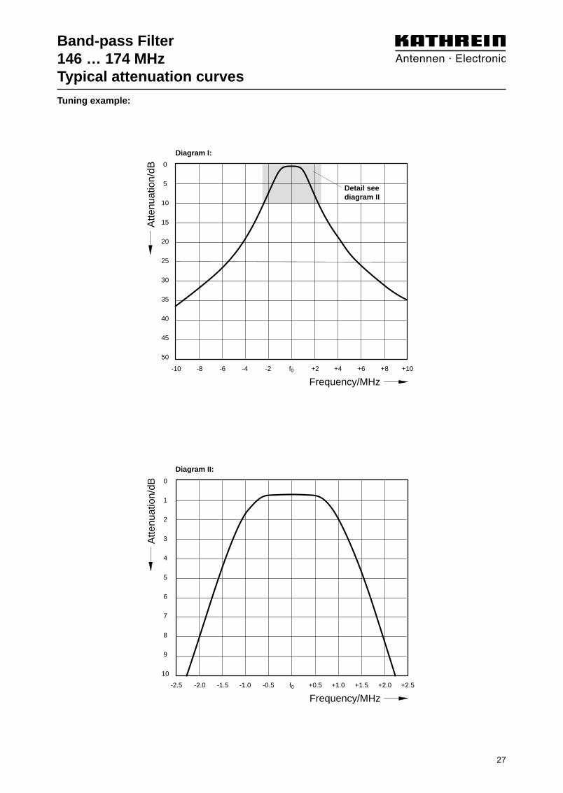
Band-pass Filter146 … 174 MHzTypical attenuation curves
0
5
10
15
20
25
30
35
40
45
50
-10 -8 -6 -4 -2 f0 +2 +4 +6 +8 +10
Atte
nuat
ion/
dB
Frequency/MHz
0
1
2
3
4
5
6
7
8
9
10
-2.5 -2.0 -1.5 -1.0 -0.5 f0 +0.5 +1.0 +1.5 +2.0 +2.5
Atte
nuat
ion/
dB
Frequency/MHz
Diagram II:
Diagram I:
Detail seediagram II
Tuning example:
27

Type No. 790 965 790 9642-cavity band-pass filter 3-cavity band-pass filter
Band-pass Filter146 … 174 MHz
Frequency range 146 … 174 MHzInsertion loss at fo 1 … 2 dB, tunable
Tuning examples
1.0 dB 1.5 dB 2.0 dB 1.0 dB 1.5 dB 2.0 dBcurve A curve B curve C curve A curve B curve C
VSWR < 1.3 (at operating frequency)Impedance 50 ΩInput power < 75 W < 50 W < 25 W < 100 W < 75 W < 50 WTemperature range –30 … +60 °CEffect of temperature –1.4 kHz / °CConnectors N female, silver-platedMaterial Brass, silver-platedColour Grey (RAL 7032)Installation With 3 screws (max. 8 mm diameter) With 4 screws (max. 8 mm diameter)
Weight 5.7 kg 8.4 kgPacking size 500 mm x 190 mm x 320 mm 500 mm x 190 mm x 440 mmDimensions (w x h x d) 419 mm x 121 mm x 232 mm 419 mm x 121 mm x 345 mm
(with connectors) (with connectors)
28
Technical Data
The band-pass filter is suitable for use as areceiving or transmitting filter, for one orseveral receivers or transmitters.
It can be used:– to improve the input selectivity of
receivers and amplifiers,– to increase the isolation of transmitters,
whose respective antennas are mounted close together,
– to suppress noise side bands and inter-modulation products,
– as a combiner component.
Design and construction:The band-pass filter consists of two or threehigh Q inductively coupled resonators. The pass band frequency and the insertionloss are tunable.
Filter characteristics: Narrow pass band with low insertion loss,high stop band attenuation, variable filterresponse corresponding to the desired stopband attenuation.
Tuning:The band-pass filter is tuned to the desiredpass band frequency and insertion loss atthe factory. Please specify desired passband frequency and insertion loss (curve A,B, C) when ordering.
The band-pass filter can also be tuned onsite using the supplied instructions.
790 964
790 965

0
2
4
6
8
10
12
14
16
18
20
-0.5 -0.4 -0.3 -0.2 -0.1 f0 +0.1 +0.2 +0.3 +0.4 +0.5
BC
Atte
nuat
ion/
dB
Frequency/MHz
A
0
10
20
30
40
50
60
70
80
90
100
-2.5 -2.0 -1.5 -1.0 -0.5 f0 +0.5 +1.0 +1.5 +2.0 +2.5
Atte
nuat
ion/
dB
Frequency/MHz
A
BC
0
10
20
30
40
50
60
70
80
90
100
-10 -8 -6 -4 -2 f0 +2 +4 +6 +8 +10
BC
Atte
nuat
ion/
dB
Frequency/MHz
A
Band-pass Filter146 … 174 MHzTypical attenuation curves
29
2-cavity band-pass filter 790 965 3-cavity band-pass filter 790 964Diagram I: Diagram I:
Diagram III: Diagram III:
Diagram II:Diagram II:
Tuning examples:
Detail seediagram II
0
10
20
30
40
50
60
70
80
90
100
-2.5 -2.0 -1.5 -1.0 -0.5 f0 +0.5 +1.0 +1.5 +2.0 +2.5
Atte
nuat
ion/
dB
Frequency/MHz
A
B
C
0
2
4
6
8
10
12
14
16
18
20
-0.5 -0.4 -0.3 -0.2 -0.1 f0 +0.1 +0.2 +0.3 +0.4 +0.5
BC
Atte
nuat
ion/
dB
Frequency/MHz
A
0
10
20
30
40
50
60
70
80
90
100
-10 -8 -6 -4 -2 f0 +2 +4 +6 +8 +10
Atte
nuat
ion/
dB
Frequency/MHz
A
BC
Detail seediagram III
Detail seediagram III
Detail seediagram II

Type No. K 64 21 25 1
Band-pass Filter146 … 174 MHz
Frequency range 146 … 174 MHzInsertion loss at fo 0.5 … 2 dB, tunable
Tuning examples0.5 dB 1.0 dB 1.5 dB 2.0 dBcurve A curve B curve C curve D
VSWR < 1.5 (at operating frequency)Impedance 50 ΩInput power < 200 WTemperature range –30 … +60 °CEffect of temperature < 0.4 kHz / °CConnectors N femaleMaterial Outer conductor: Aluminium
Inner conductor: Brass, silver-platedInstallation Free standing or wall mounting
with mounting anglesAttached hardware Band-pass filter with 2 mounting angles
and 2 connecting piecesWeight 9 kgPacking size 207 mm x 865 mm x 207 mmDimensions (w x h x d) 190 mm x max. 770 mm x 190 mm
(with tuning rod)
30
Technical Data
The band-pass filter is suitable for use as a receiving or transmitting filter for onereceiver or transmitter.
It can be used:– to improve the input selectivity of
receivers and amplifiers,– to increase the isolation of transmitters,
whose respective antennas are mounted close together,
– to suppress noise side bands and inter-modulation products,
– as a combiner component.
Design and construction:The band-pass filter is designed as a tem-perature stabilized λ/4 coaxial resonator.The pass band frequency and the insertionloss are tunable.
Filter characteristics: Narrow pass band with low insertion loss,high stop band attenuation, variable filterresponse corresponding to the desired stopband attenuation.
Combination of several band-pass filters:Several band-pass filters can be intercon-nected using cables of an electrical lengthof λ/4. This causes an increase in the edgesteepness of the filter curve as well as thebandwidth of the pass band. The individualfilters are tuned to the center frequency ofthe complete filter.
Insertion loss of the filter combination = Sum insertion loss of the individual filters +cable attenuation of the interconnectingcables (about 0.1 dB per cable). Stop band attenuation of the filter combina-tion = Sum stop band attenuation of indi-vidual filters + additional stop band attenua-tion.
If the stop band attenuation of the individualfilters exceeds 10 dB, approximately the following applies: additional stop band attenuation = (n – 1) x 5 dB;n = number of individual filters.For special applications band-pass filterscan also be interconnected with S-P filters.
Tuning:The band-pass filter is tuned to the desiredpass band frequency and insertion loss atthe factory. Please specify desired pass bandfrequency and insertion loss (curve A, B, C,D) when ordering.
The band-pass filter can also be tuned onsite using the supplied instructions.

0
1
2
3
4
5
6
7
8
9
10
-0.5 -0.4 -0.3 -0.2 -0.1 f0 +0.1 +0.2 +0.3 +0.4 +0.5
BCD
Atte
nuat
ion/
dB
Frequency/MHz
A
Band-pass Filter146 … 174 MHzTypical attenuation curves
31
Diagram I:
Diagram III:
Diagram II:
Tuning examples:
0
5
10
15
20
25
30
35
40
45
50
-10 -8 -6 -4 -2 f0 +2 +4 +6 +8 +10
Atte
nuat
ion/
dB
Frequency/MHz
A
B
CD
Detail seediagram II
0
5
10
15
20
25
30
35
40
45
50
-2.5 -2.0 -1.5 -1.0 -0.5 f0 +0.5 +1.0 +1.5 +2.0 +2.5
Atte
nuat
ion/
dB
Frequency/MHz
A
BC
D
Detail seediagram III
32
Type No. N female K 64 31 21 K 64 32 21 K 64 33 217-16 female K 64 31 27 K 64 32 27 K 64 33 27
Band-stop Filter146 … 174 MHz
Version 1-cavity 2-cavity 3-cavityband-stop filter band-stop filter band-stop filter
Frequency range 146 … 174 MHz Impedance 50 ΩInput power < 300 W (at insertion loss < 1 dB)Temperature range –30 … +60 °CTemperature coefficient < 18 x 10 –6 / °CMaterial Brass, silver-platedColour Grey (RAL 7032)Montage With 4 screws (max. 6 mm diameter)Weight 5.2 kg 10.4 kg 15.5 kgPacking size 207 mm x 207 mm x 575 mm 330 mm x 205 mm x 550 mm 435 mm x 205 mm x 505 mmDimensions (w x h x d) 120 mm x 148 mm x 420 mm 240 mm x 148 mm x 420 mm 360 mm x 148 mm x 420 mm
Technical Data
The band-stop filter is used:– to attenuate interfering signals,– to increase the coupling isolation
between transmitter and receiver.
Design and construction:The band-stop filter consists of capacitivelyshortened λ/4 coaxial resonators. The resonators of the multi cavity band-stopfilters are interconnected by cables of λ/4length. The stop band frequency and thestop band attenuation are tunable.
Filter characteristics: Narrow stop band with high stop bandattenuation, low insertion loss outside thestop band.
Tuning:The band-stop filter is tuned to the desiredstop band frequency at the factory. When ordering please specify stop bandfrequency.
The band-stop filter can also be tuned onsite using the supplied instructions.
The resonators of the 2-cavity or 3-cavityband-stop filters can be tuned indepen-dently. In this way, 2 or 3 different inter-fering signals can be suppressed or onesingle interfering signal can be especially attenuated.
1-cavity band-stop filterK 64 31 21
2-cavity band-stop filterK 64 32 21
3-cavity band-stop filterK 64 33 27
33
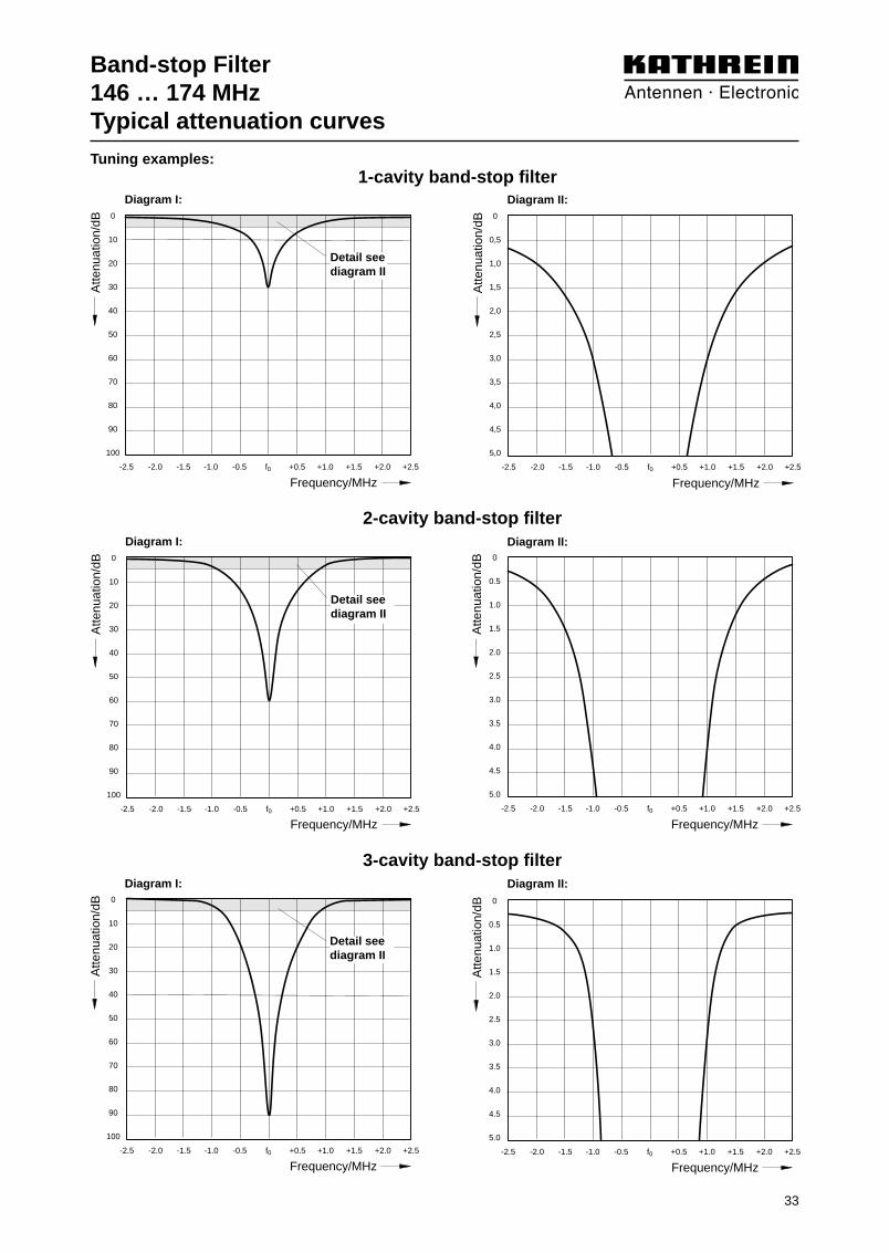
Band-stop Filter146 … 174 MHzTypical attenuation curves
1-cavity band-stop filter
2-cavity band-stop filter
3-cavity band-stop filter
0
10
20
30
40
50
60
70
80
90
100
-2.5 -2.0 -1.5 -1.0 -0.5 f0 +0.5 +1.0 +1.5 +2.0 +2.5
Atte
nuat
ion/
dB
Frequency/MHz
0
10
20
30
40
50
60
70
80
90
100
-2.5 -2.0 -1.5 -1.0 -0.5 f0 +0.5 +1.0 +1.5 +2.0 +2.5
Atte
nuat
ion/
dB
Frequency/MHz
0
0.5
1.0
1.5
2.0
2.5
3.0
3.5
4.0
4.5
5.0
-2.5 -2.0 -1.5 -1.0 -0.5 f0 +0.5 +1.0 +1.5 +2.0 +2.5
Atte
nuat
ion/
dB
Frequency/MHz
0
10
20
30
40
50
60
70
80
90
100
-2.5 -2.0 -1.5 -1.0 -0.5 f0 +0.5 +1.0 +1.5 +2.0 +2.5
Atte
nuat
ion/
dB
Frequency/MHz
0
0.5
1.0
1.5
2.0
2.5
3.0
3.5
4.0
4.5
5.0
-2.5 -2.0 -1.5 -1.0 -0.5 f0 +0.5 +1.0 +1.5 +2.0 +2.5
Atte
nuat
ion/
dB
Frequency/MHz
0
0,5
1,0
1,5
2,0
2,5
3,0
3,5
4,0
4,5
5,0
-2.5 -2.0 -1.5 -1.0 -0.5 f0 +0.5 +1.0 +1.5 +2.0 +2.5
Atte
nuat
ion/
dBFrequency/MHz
Diagram I:
Diagram I:
Diagram I:
Detail seediagram II
Detail seediagram II
Diagram II:
Diagram II:
Diagram II:
Detail seediagram II
Tuning examples:
S-P Filter146 … 174 MHz
The S-P filter (Stop-Pass filter) is used toattenuate interfering signals located extre-mely close to the operational frequency.
It can be used:– in the transmission path to suppress side
band noise and to attenuate intermodula-tion products at the receiving frequencies,
– in the receiving path to attenuate trans-mitting frequencies,
– as a component for combiners with very low frequency spacing.
Design and construction:The S-P filter is designed as a high Q tem-perature stabilized λ/4 coaxial resonator.Using a special temperature stabilized coupling, high stop band attenuation can be adjusted very close to the pass band frequency.
Filter characteristics: Narrow pass band with low insertion loss,high stop band attenuation at the stop bandfrequency. Even in case of very small spac-ing between the pass band and the stopband frequency a high stop band attenuationis achieved, which can not be achieved usingstandard band-pass filters of the same size.
Combination of several S-P filters:Several S-P filters can be interconnected by cables with an electrical length of λ/4.
Insertion loss of the filter combination = Sum insertion loss of the individual filters + cable attenuation of the interconnectingcables (about 0.1 dB per cable). Stop bandattenuation of the filter combination = Sum stop band attenuation of the individualfilters + additional stop band attenuation.
If the stop band attenuation of the individualfilters exceeds 10 dB, approximately the following applies:additional stop band attenuation =(n – 1) x 5 dB;n = number of individual filters.For special applications S-P filters can alsobe interconnected with band-pass filters.
Tuning:The S-P filter is tuned to the desired passband and stop band frequency at the factory.Please specify desired pass band and stopband frequency when ordering.
The S-P filter can also be tuned on site usingthe supplied instructions.
Type No. 792 119 728 024 K 64 21 26 1Frequency range 146 … 174 MHz Frequency spacingPass band / stop band frequency 60 – 100 kHz 80 – 150 kHz 1) > 300 kHz
150 – 300 kHz 2)
> 300 kHz 3)
Insertion loss < 1.0 dB < 0.7 dB 0.5 ±0.15 dBVSWR < 1.5 (at operating frequency)Impedance 50 ΩInput power < 15 W < 15 W 1) < 200 W
< 100 W 2)
< 200 W 3)
Temperature range 0 … +35 °C 0 … +35 °C 1) –20 ... +60 °C0 ... +50 °C 2)
–20 ... +60 °C 3)
Effect of temperature < 0.4 kHz / °CConnectors N femaleMaterial Outer conductor: Aluminium,
Inner conductor: Brass, silver-platedInstallation Free standing or wall mountingAttached hardware S-P filter with 2 mounting angles
and 2 connecting piecesWeight Approx. 9 kgPacking size 207 mm x 865 mm x 207 mmDimensions (w x h x d) 190 mm x max. 770 mm x 190 mm
(with tuning rod)
Technical Data
K 64 21 26 1728 024792 119
34

S-P Filter146 … 174 MHzTypical attenuation curves
35
792 119
728 024
K 64 21 26 1
0
5
10
15
20
25
30
35
40
45
50
-0.3 -0.2 -0.1 f0 +0.1
A
B
C
D
E
A
B
C
D
E
Atte
nuat
ion/
dB
Frequency/MHz
0
5
10
15
20
25
30
35
40
45
50
-0.15 -0.1 -0.05 f0 +0.05
AB
CD
E
ABCDE
Atte
nuat
ion/
dB
Frequency/MHz
0
5
10
15
20
25
30
35
40
45
50
-0.1 f0 +0.1 +0.2 +0.3
A
B
C
D
E
A
B
C
D
E
Atte
nuat
ion/
dB
Frequency/MHz
0
5
10
15
20
25
30
35
40
45
50
+3 +2 +1 f0 -1
A
B
CD
E
F
G
H
A
BCDEFGH
Atte
nuat
ion/
dB
Frequency/MHz
0
5
10
15
20
25
30
35
40
45
50
-1 f0 +1 +2 +3
A
BCDEFGH
A
B
C
D
E
F
G
H
Atte
nuat
ion/
dB
Frequency/MHz
0
5
10
15
20
25
30
35
40
45
50
-0.05 f0 +0.05 +0.1 +0.15
AB
CD
E
ABCDE
Atte
nuat
ion/
dBFrequency/MHz
Diagram I:
Diagram I:
Diagram I:
Diagram II:
Diagram II:
Diagram II:
Tuning examples:

Number of resonators 3 4Frequency range 146 … 174 MHz
Tuning examplesBand spacing 3.5 MHz 4.6 MHz 6 MHz 3 MHz 4.6 MHz 6 MHzSwitching bandwidth 0.1 MHz 0.1 MHz 0.5 MHz 1.0 MHz 1.0 MHz 0.1 MHz 0.5 MHz 1.0 MHz 1.9 MHz * 2.0 MHzInsertion loss < 1.2 dB < 1.0 dB < 1.0 dB < 1.2 dB < 1.0 dB < 1.2 dB < 1.2 dB < 1.3 dB < 2.0 dB < 1.3 dBStop band attenuation > 60 dB > 70 dB > 60 dB > 55 dB > 60 dB > 65 dB > 70 dB > 60 dB > 55 dB > 60 dBVSWR < 1.4 (at operating frequency)Impedance 50 ΩInput power < 100 W (–30 … +55 °C) / < 50 W (+55 … +70 °C)
* < 50 W (–30 … +55 °C) / < 30 W (+55 … +70 °C)Temperature range –30 … +70 °CConnectors N femaleMaterial S-P resonators: Aluminium / copper, silver-plated; cable: RG 223/UInstallation With 4 screws (max. 4 mm diameter)Weight 1.0 kg 1.2 kgPacking size 235 mm x 61 mm x 165 mmDimensions (w x h x d) 155 mm x 50 mm x 160 mm 195 mm x 50 mm x 160 mm
(with connectors) (with connectors)
S-P Filter146 … 174 MHz
36
Technical Data
The S-P filter (Stop-Pass filter) is suitable forattenuating interfering frequencies, close to theoperational frequency band. It is designed foroperation with one transmitter respectively withone or several receivers.
It can be used:– in the transmission path for suppressing side
band noise and for attenuating intermodulationproducts at the receiving frequencies,
– in the receiving path for attenuating transmittingfrequencies,
– as a duplexer component.
Design and construction:The S-P filter consists of three or four S-Presonators, interconnected by cables of definedelectrical length.
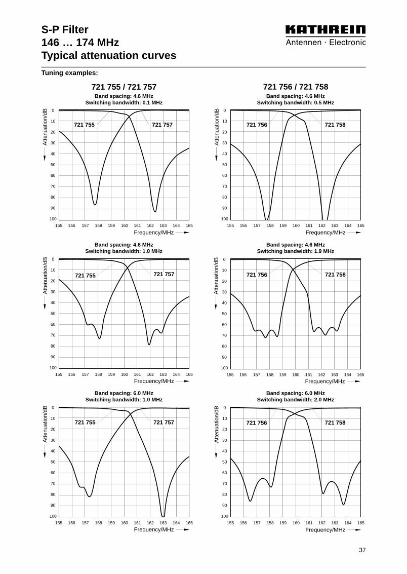
Filter characteristics: 721 755 / 721 756: Broad pass band with low insertion loss in the low band, high stop bandattenuation at the stop band frequencies in thehigh band.721 757 / 721 758: Broad pass band with low insertion loss in the high band, high stop bandattenuation at the stop band frequencies in thelow band.
Tuning:The S-P filter can only be tuned at the factorybecause of its special design. Special requestssuch as: Special band spacing, switching band-widths or attenuation can be taken into account.When ordering please specify the desired highand low band frequencies.
Type No. 721 755 (Pass band: Low band/Stop band: High band) 721 756 (Pass-band: Low band/Stop band: High band)
721 757 (Pass band: High band/Stop band: Low band) 721 758 (Pass-band: High band/Stop band: Low band)
721 755721 757
S-P Filter146 … 174 MHzTypical attenuation curves
37
721 755 / 721 757 721 756 / 721 758Band spacing: 4.6 MHz
Switching bandwidth: 0.1 MHzBand spacing: 4.6 MHz
Switching bandwidth: 0.5 MHz
Band spacing: 4.6 MHzSwitching bandwidth: 1.0 MHz
Band spacing: 4.6 MHzSwitching bandwidth: 1.9 MHz
Band spacing: 6.0 MHzSwitching bandwidth: 1.0 MHz
Band spacing: 6.0 MHzSwitching bandwidth: 2.0 MHz
Tuning examples:
0
10
20
30
40
50
60
70
80
90
100
155 156 157 158 159 160 161 162 163 164 165
Atte
nuat
ion/
dB
Frequency/MHz
0
10
20
30
40
50
60
70
80
90
100
155 156 157 158 159 160 161 162 163 164 165
Atte
nuat
ion/
dB
Frequency/MHz
0
10
20
30
40
50
60
70
80
90
100
155 156 157 158 159 160 161 162 163 164 165
Atte
nuat
ion/
dB
Frequency/MHz
0
10
20
30
40
50
60
70
80
90
100
155 156 157 158 159 160 161 162 163 164 165
Atte
nuat
ion/
dB
Frequency/MHz
0
10
20
30
40
50
60
70
80
90
100
155 156 157 158 159 160 161 162 163 164 165
Atte
nuat
ion/
dB
Frequency/MHz
0
10
20
30
40
50
60
70
80
90
100
155 156 157 158 159 160 161 162 163 164 165
Atte
nuat
ion/
dB
Frequency/MHz
721 757721 755
721 757721 755
721 757721 755
721 758721 756
721 758721 756
721 758721 756
S-P Filter146 … 174 MHz
38
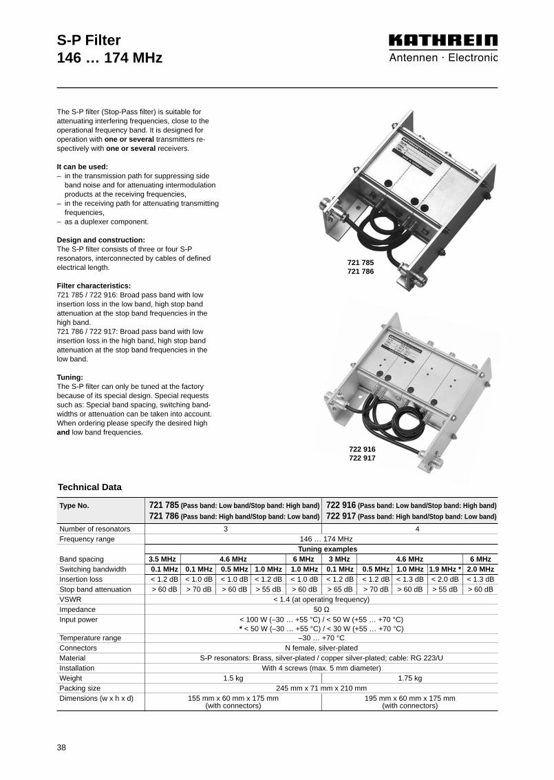
Technical Data
The S-P filter (Stop-Pass filter) is suitable forattenuating interfering frequencies, close to theoperational frequency band. It is designed foroperation with one or several transmitters re-spectively with one or several receivers.
It can be used:– in the transmission path for suppressing side
band noise and for attenuating intermodulationproducts at the receiving frequencies,
– in the receiving path for attenuating transmittingfrequencies,
– as a duplexer component.
Design and construction:The S-P filter consists of three or four S-Presonators, interconnected by cables of defined electrical length.
Filter characteristics: 721 785 / 722 916: Broad pass band with low insertion loss in the low band, high stop bandattenuation at the stop band frequencies in thehigh band.721 786 / 722 917: Broad pass band with low insertion loss in the high band, high stop bandattenuation at the stop band frequencies in thelow band.
Tuning:The S-P filter can only be tuned at the factorybecause of its special design. Special requestssuch as: Special band spacing, switching band-widths or attenuation can be taken into account.When ordering please specify the desired highand low band frequencies.
Type No. 721 785 (Pass band: Low band/Stop band: High band) 722 916 (Pass band: Low band/Stop band: High band)
721 786 (Pass band: High band/Stop band: Low band) 722 917 (Pass band: High band/Stop band: Low band)
Number of resonators 3 4Frequency range 146 … 174 MHz
Tuning examplesBand spacing 3.5 MHz 4.6 MHz 6 MHz 3 MHz 4.6 MHz 6 MHzSwitching bandwidth 0.1 MHz 0.1 MHz 0.5 MHz 1.0 MHz 1.0 MHz 0.1 MHz 0.5 MHz 1.0 MHz 1.9 MHz * 2.0 MHzInsertion loss < 1.2 dB < 1.0 dB < 1.0 dB < 1.2 dB < 1.0 dB < 1.2 dB < 1.2 dB < 1.3 dB < 2.0 dB < 1.3 dBStop band attenuation > 60 dB > 70 dB > 60 dB > 55 dB > 60 dB > 65 dB > 70 dB > 60 dB > 55 dB > 60 dBVSWR < 1.4 (at operating frequency)Impedance 50 ΩInput power < 100 W (–30 … +55 °C) / < 50 W (+55 … +70 °C)
* < 50 W (–30 … +55 °C) / < 30 W (+55 … +70 °C)Temperature range –30 … +70 °CConnectors N female, silver-platedMaterial S-P resonators: Brass, silver-plated / copper silver-plated; cable: RG 223/UInstallation With 4 screws (max. 5 mm diameter)Weight 1.5 kg 1.75 kgPacking size 245 mm x 71 mm x 210 mmDimensions (w x h x d) 155 mm x 60 mm x 175 mm 195 mm x 60 mm x 175 mm
(with connectors) (with connectors)
721 785721 786
722 916722 917

S-P Filter146 … 174 MHzTypical attenuation curves
39
721 785 / 721 786 722 916 / 722 917Band spacing: 4.6 MHz
Switching bandwidth: 0.1 MHzBand spacing: 4.6 MHz
Switching bandwidth: 0.5 MHz
Band spacing: 4.6 MHzSwitching bandwidth: 1.0 MHz
Band spacing: 4.6 MHzSwitching bandwidth: 1.9 MHz
Band spacing: 6.0 MHzSwitching bandwidth: 1.0 MHz
Band spacing: 6.0 MHzSwitching bandwidth: 2.0 MHz
Tuning examples:
0
10
20
30
40
50
60
70
80
90
100
155 156 157 158 159 160 161 162 163 164 165
Atte
nuat
ion/
dB
Frequency/MHz
0
10
20
30
40
50
60
70
80
90
100
155 156 157 158 159 160 161 162 163 164 165
Atte
nuat
ion/
dB
Frequency/MHz
0
10
20
30
40
50
60
70
80
90
100
155 156 157 158 159 160 161 162 163 164 165
Atte
nuat
ion/
dB
Frequency/MHz
0
10
20
30
40
50
60
70
80
90
100
155 156 157 158 159 160 161 162 163 164 165
Atte
nuat
ion/
dB
Frequency/MHz
0
10
20
30
40
50
60
70
80
90
100
155 156 157 158 159 160 161 162 163 164 165
Atte
nuat
ion/
dB
Frequency/MHz
0
10
20
30
40
50
60
70
80
90
100
155 156 157 158 159 160 161 162 163 164 165
Atte
nuat
ion/
dB
Frequency/MHz
722 916 722 917
722 916 722 917
722 916 722 917
721 786721 785
721 786721 785
721 786721 785

Type No. 729 870
Low-pass Filter146 – 174 MHz
Pass band 146 – 174 MHzInsertion loss < 0.5 dB (146 – 174 MHz)Stop band 292 – 1050 MHzStop band attenuation > 60 dB (292 – 1050 MHz)VSWR < 1.4 (146 – 174 MHz)Impedance 50 ΩInput power < 40 WTemperature range –30 … +60 °CConnectors N male at a 250 mm long cableMaterial Housing: Aluminium
Cabel: RG 223/UInstallation With 2 screws (max. 4 mm diameter)Weight 0.3 kgPacking size 190 mm x 65 mm x 110 mmDimensions (w x h x d) 88 mm x 40 mm x 64 mm
(without connectors)
40
Technical Data
The low-pass filter is suitable for use as areceiving or transmitting filter.
It can be used:– to suppress harmonics in the transmitting
path,– to suppress interfering signals in the
receiving path.
Design and construction:The low pass filter consists of lumped L-Celements.
Filter characteristics: Broad pass band with low insertion loss,high stop band attenuation in the stop band.
Installation:The right angle mounting plate allowshorizontal as well as vertical installation.

Low-pass Filter146 – 174 MHzTypical attenuation curves
41
Diagram I:
Diagram II:
0
10
20
30
40
50
60
70
80
90
100
100 200 300 400 500 600 700 800 900 1000 1100
Atte
nuat
ion/
dB
Frequency/MHz
0
0.1
0.2
0.3
0.4
0.5
0.6
0.7
0.8
0.9
1.0
100 110 120 130 140 150 160 170 180 190 200
Atte
nuat
ion/
dB
Frequency/MHz
Detail seediagram II

Type No. K 65 00 21
Band-pass Filter380 … 470 MHz
Frequency range 380 … 470 MHzInsertion loss < 1.2 dBVSWR < 1.2Impedance 50 ΩInput power < 50 WTemperature range –30 … +60 °CConnectors N femaleMaterial Brass, silver-platedColour Grey (RAL 7032)Installation With 2 screws (max. 5 mm diameter)Weight 0.6 kgPacking size 315 mm x 90 mm x 95 mmDimensions (w x h x d) 158 mm x 40 mm x 83 mm
(without connectors and tuning bolts)
Technical Data
The band-pass filter is suitable as receivingor transmitting filter, for one or more trans-mitting or receiving channels.
It can be used:– to improve the input selectivity of
receivers and amplifiers,– to increase the isolation of transmitters,
whose respective antennas are mounted close together,
– to suppress noise sidebands and inter-modulation products,
– as a component to form combiners.
Design and construction:The band-pass filter consists of two capa-citively coupled resonators.
Filter characteristics: Narrow pass band range with low insertionloss, high stop band attenuation.
Tuning:The band-pass filter is tuned to the desiredpass band frequency at the factory. Pleasespecify desired pass band frequency whenordering. The band-pass filter can also betuned on site using the supplied instruc-tions.
42

Band-pass Filter380 … 470 MHzTypical attenuation curves
0
5
10
15
20
25
30
35
40
45
50
-25 -20 -15 -10 -5 f0 +5 +10 +15 +20 +25
Attenuatio
n/d
B
Frequency/MHz
0
1
2
3
4
5
6
7
8
9
10
-5 -4 -3 -2 -1 f0 +1 +2 +3 +4 +5
Atte
nuat
ion/
dB
Frequency/MHz
Diagram II:
Diagram I:
Detail seediagram II
Tuning example:
43

44
Type No. 790 967 790 9662-cavity band-pass filter 3-cavity band-pass filter
Band-pass Filter380 … 470 MHz
Frequency range 380 … 470 MHzInsertion loss 1 … 2 dB, tunable
1.0 dB 1.5 dB 2.0 dB 1.0 dB 1.5 dB 2.0 dBcurve A curve B curve C curve A curve B curve C
VSWR < 1.3 (at pass band frequency)Impedance 50 ΩInput power < 50 W < 35 W < 25 W < 75 W < 50 W < 35 WTemperature range –30 … +60 °CEffect of temperature –2.5 kHz / °CConnectors N female, silver-platedMaterial Brass, silver-platedColour Grey (RAL 7032)Installation With 3 screws (M6) With 4 screws (M6)Weight 3.2 kg 4.5 kgPacking size 310 mm x 210 mm x 310 mm 410 mm x 215 mm x 255 mmDimensions (w x h x d) 232 mm x 121 mm x 188 mm 345 mm x 121 mm x 188 mm
(with connectors) (with connectors)
Technical Data
The band-pass filter is suitable as receivingor transmitting filter, for one or more trans-mitting or receiving channels.
It can be used:– to improve the input selectivity of recei-
vers and amplifiers,– to increase the isolation of transmitters,
whose respective antennas are mounted close together,
– to suppress noise sidebands and inter-modulation products,
– as a component to form combiners.
Design and construction:The band-pass filter consists of two or threehigh Q inductively coupled resonators. Thepass band frequency, the coupling betweenthe resonators as well as the input and out-put coupling are adjustable.
Filter characteristics: Narrow pass band range with low insertionloss, high stop band attenuation, variablefilter response corresponding to the desiredstop band attenuation.
Tuning:The band-pass filter is tuned to the desiredpass band frequency and insertion loss atthe factory. Please specify desired passband frequency and insertion loss (curve A,B, C) when ordering.
The band-pass filter can also be tuned onsite using the supplied instructions.
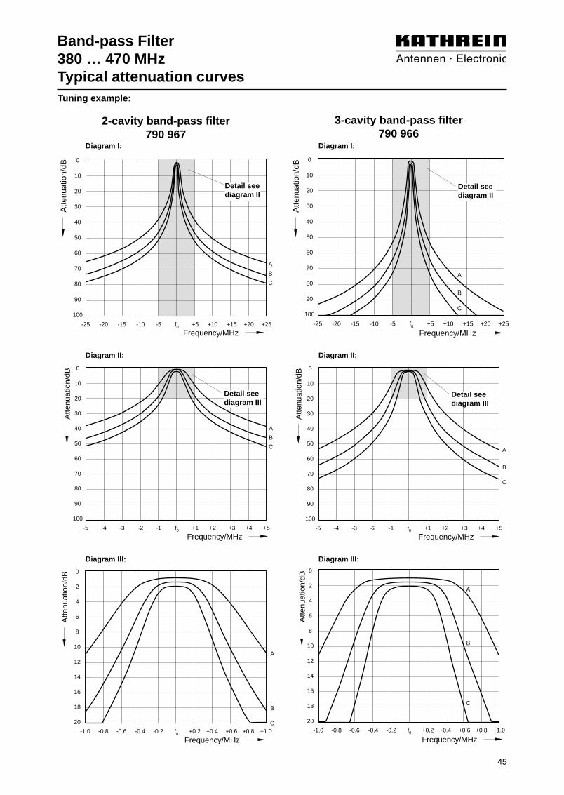
790 967
790 966
45
Band-pass Filter380 … 470 MHzTypical attenuation curves
0
10
20
30
40
50
60
70
80
90
100
-25 -20 -15 -10 -5 f0 +5 +10 +15 +20 +25
A
B
C
Atte
nuat
ion/
dB
Frequency/MHz
0
10
20
30
40
50
60
70
80
90
100
-5 -4 -3 -2 -1 f0 +1 +2 +3 +4 +5
A
B
C
Atte
nuat
ion/
dB
Frequency/MHz
0
2
4
6
8
10
12
14
16
18
20
-1.0 -0.8 -0.6 -0.4 -0.2 f0 +0.2 +0.4 +0.6 +0.8 +1.0
A
B
C
Atte
nuat
ion/
dB
Frequency/MHz
0
10
20
30
40
50
60
70
80
90
100
-25 -20 -15 -10 -5 f0 +5 +10 +15 +20 +25
A
B
C
Atte
nuat
ion/
dB
Frequency/MHz
0
10
20
30
40
50
60
70
80
90
100
-5 -4 -3 -2 -1 f0 +1 +2 +3 +4 +5
A
B
C
Atte
nuat
ion/
dB
Frequency/MHz
0
2
4
6
8
10
12
14
16
18
20
-1.0 -0.8 -0.6 -0.4 -0.2 f0 +0.2 +0.4 +0.6 +0.8 +1.0
A
B
C
Atte
nuat
ion/
dB
Frequency/MHz
2-cavity band-pass filter790 967
3-cavity band-pass filter790 966
Diagram III:
Diagram II:
Diagram I:
Detail seediagram II
Detail seediagram III
Diagram III:
Diagram II:
Diagram I:
Detail seediagram II
Detail seediagram III
Tuning example:

46
Band-pass Filter380 … 470 MHz
The band-pass filter is suitable as receivingor transmitting filter, for one transmitting orreceiving channel.
It can be used:– to improve the input selectivity of
receivers and amplifiers,– to increase the isolation of transmitters,
whose respective antennas are mounted close together,
– to suppress noise sidebands and inter-modulation products,
– as a component to form combiners.
Design and construction:The band-pass filter is designed as a tem-perature stabilized λ/4 coaxial resonator. The pass band frequency as well as theinput and output coupling are adjustable.
Filter characteristics: Narrow pass band range with low insertionloss, high stop band attenuation, variable filter response corresponding to the desiredstop band attenuation.
Combination of several band-pass filters:Several band-pass filters can be intercon-nected using cables of an electrical length of λ/4. This causes an increase in the edgesteepness of the filter curve as well as thebandwidth of the pass band. The individualfilters are tuned to the center frequency ofthe complete filter.
Insertion loss of the filter combination = Sum insertion loss of the individual filters + cable attenuation of the interconnectingcables (about 0.1 dB per cable). Stop band attenuation of the filter combination = Sum stop band attenuation of individual filters + additional stop bandattenuation.
If the stop band attenuation of the individualfilters exceeds 10 dB, approximately the following applies: additional stop band attenuation = (n – 1) x 5 dB;n = number of individual filters.For special applications band-pass filterscan also be interconnected with S-P filters.
Tuning:The band-pass filter is tuned to the desiredpass band frequency and insertion loss at thefactory. Please specify desired pass bandfrequency and insertion loss (curve A, B, C,D) when ordering. The pass band filter can also be tuned onsite using the supplied instructions.
Type No. K 65 21 25 1Frequency range 380 … 470 MHz
Insertion loss at fo 0.5 … 2 dB, tunable
Tuning examples
0.5 dB 1.0 dB 1.5 dB 2.0 dBcurve A curve B curve C curve D
VSWR < 1.5 (at pass band frequency)
Impedance 50 ΩInput power < 200 W
Temperature range –30 … +60 °C
Effect of temperature < 1.2 kHz / °C
Connectors N female
Material Outer conductor: AluminiumInner conductor: Brass, silver-plated
Mounting Free standing or wall mountingwith mounting angles
Attached hardware Band-pass filter with 2 mounting anglesand 2 connecting pieces
Weight 5 kg
Packing size 210 mm x 490 mm x 210 mm
Dimensions (w x h x d) 190 mm x max. 380 mm x 190 mm (with tuning rod)
Technical Data

47
Band-pass Filter380 … 470 MHzTypical attenuation curves
0
5
10
15
20
25
30
35
40
45
50
-25 -20 -15 -10 -5 f0 +5 +10 +15 +20 +25
A
B
C
D
Atte
nuat
ion/
dB
Frequency/MHz
0
5
10
15
20
25
30
35
40
45
50
-5 -4 -3 -2 -1 f0 +1 +2 +3 +4 +5
A
B
C
D
Atte
nuat
ion/
dB
Frequency/MHz
0
2
4
6
8
10
12
14
16
18
20
-1.0 -0.8 -0.6 -0.4 -0.2 f0 +0.2 +0.4 +0.6 +0.8 +1.0
A
B
C
D
Atte
nuat
ion/
dB
Frequency/MHz
Diagram III:
Diagram II:
Diagram I:
Detail seediagram II
Detail seediagram III
Tuning example:

48
Band-stop Filter380 … 470 MHz
2-cavity band-stop filterK 65 32 21
3-cavity band-stop filterK 65 33 21
1-cavity band-stop filterK 65 31 21
The band-stop filter is used:– to attenuate interfering signals,– to increase the coupling attenuation
between transmitter and receiver.
Design and construction:The band-stop filter consists of capacitivelyshortened λ/4 coaxial resonators. The reso-nators of the 2- and 3-cavity band-stop filterare interconnected by cables of λ/4 length.
Filter characteristics: Narrow stop band range with high stopband attenuation, low insertion loss outsidethe stop band range.
Tuning:The band-stop filter is tuned to the desiredstop band frequency at the factory. Whenordering please specify stop band frequency.
The band-stop filter can also be tuned onsite using the supplied instructions.
The resonators of the 2-cavity or 3-cavityband-stop filters can be tuned indepen-dently. In this way, 2 or 3 different interfe-ring signals can be suppressed or onesingle interfering signal can be especially attenuated.
Version 1-cavity 2-cavity 3-cavityband-stop filter band-stop filter band-stop filter
Frequency range 380 … 470 MHz Impedance 50 ΩInput power < 300 W (insertion loss < 1 dB)Temperature range –30 … +60 °CTemperature coefficient 18 x 10–6 / °CMaterial Brass, silver-platedColour Grey (RAL 7032)Installation With 4 screws (max. 6 mm diameter)Weight 5.6 kg 11.2 kg 17.0 kgPacking size by mm 585 x 170 x 170 585 x 170 x 285 585 x 170 x 405Dimensions by mm (w x h x d) 426 x 130 x 122 426 x 130 x 240 426 x 130 x 360
Type No. N female K 65 31 21 K 65 32 21 K 65 33 217-16 female K 65 31 27 K 65 32 27 K 65 33 27
Technical Data

49
1-cavity band-stop filter
2-cavity band-stop filter
3-cavity band-stop filter
0
10
20
30
40
50
60
70
80
90
100
-5 -4 -3 -2 -1 f0 +1 +2 +3 +4 +5
Atte
nuat
ion/
dB
Frequency/MHz
0
10
20
30
40
50
60
70
80
90
100
-5 -4 -3 -2 -1 f0 +1 +2 +3 +4 +5
Atte
nuat
ion/
dB
Frequency/MHz
0
0.5
1.0
1.5
2.0
2.5
3.0
3.5
4.0
4.5
5.0
-5 -4 -3 -2 -1 f0 +1 +2 +3 +4 +5
Atte
nuat
ion/
dB
Frequency/MHz
0
10
20
30
40
50
60
70
80
90
100
-5 -4 -3 -2 -1 f0 +1 +2 +3 +4 +5
Atte
nuat
ion/
dB
Frequency/MHz
0
0.5
1.0
1.5
2.0
2.5
3.0
3.5
4.0
4.5
5.0
-5 -4 -3 -2 -1 f0 +1 +2 +3 +4 +5
Atte
nuat
ion/
dB
Frequency/MHz
0
0.5
1.0
1.5
2.0
2.5
3.0
3.5
4.0
4.5
5.0
-5 -4 -3 -2 -1 f0 +1 +2 +3 +4 +5
Atte
nuat
ion/
dB
Frequency/MHz
Diagram I: Diagram II:
Detail seediagram II
Diagram I: Diagram II:
Detail seediagram II
Diagram I: Diagram II:
Detail seediagram II
Tuning example:
Band-stop Filter380 … 470 MHzTypical attenuation curves

50
Frequency range 380 … 470 MHz Insertion loss 0.5 ±0.15 dBVSWR < 1.5 (at pass band frequency)Impedance 50 ΩInput power < 200 WTemperature range –20 … +60 °CEffect of temperature < 1.2 kHz / °CConnectors N femaleMaterial Outer conductor: Aluminium
Inner conductor: Brass, silver-platedInstallation Free standing or wall mountingAttached hardware S-P filter with 2 mounting angles
and 2 connecting piecesWeight 5 kgPacking size 210 mm x 490 mm x 210 mmDimensions (w x h x d) 190 mm x max. 350 mm x 190 mm
(with tuning rod)
S-P Filter380 … 470 MHz
The S-P filter (Stop-Pass filter) is used to attenuateinterfering signals located extremely close to theoperational frequency.
It can be used:– in the transmission path to suppress side band
noise and to attenuate intermodulation productsat the receiving frequecies,
– in the receiving path to attenuate transmitting frequencies,
– as a component for combiners with very lowfrequency spacing.
Design and construction:The S-P filter is designed as a high Q temperaturestabilized λ/4 coaxial resonator. Using a specialtemperature stabilized coupling, high stop bandattenuation can be adjusted very close to the passband frequency.
Filter characteristics: Narrow pass band range with low insertion loss,high stop band attenuation at the stop band fre-quency. Even in case of very small spacingbetween the pass band and the stop band fre-quency a high stop band attenuation is achieved,which can not be achieved using standard band-pass filters of the same size.
Combination of several S-P filters:Several S-P filters can be interconnected by cableswith an electrical length of λ/4.
Insertion loss of the filter combination = Sum inser-tion loss of the individual filters + cable attenuationof the interconnecting cables (about 0.1 dB percable). Stop band attenuation of the filter combina-tion = Sum stop band attenuation of the individualfilters + additional stop band attenuation.
If the stop band attenuation of the individual filtersexceeds 10 dB, approximately the following applies:additional stop band attenuation = (n – 1) x 5 dB;n = number of individual filters.For special applications S-P filters can also be inter-connected with band-pass filters.
Tuning:The S-P filter is tuned to the desired pass band andstop band frequency at the factory. Please specifydesired pass band and stop band frequency whenordering.
The S-P filter can also be tuned on site using thesupplied instructions.
Customized versionsFor special applications S-P filters for even lowerfrequency spacing or lower insertion loss are available.
Type No. K 65 21 26 1
Technical Data

51
S-P Filter380 … 470 MHzTypical attenuation curves
Curve Frequency spacing pass band frequency / stop band frequency
A 0.5 MHzB 1.0 MHzC 1.5 MHzD 2.0 MHzE 3.0 MHzF 4.0 MHz
+1 +2 +3 +4
0
5
10
15
20
25
30
35
40
A
B
C
E
F
-1 f0
ABCDEF
Frequency/MHz
Atte
nuat
ion/
dB
-0.5 f0 +0.5
1
2
3
4
dB
D
f0
+1
ABCDEF
A
B
C
E
F
dB
1
2
3
4
-4 -3 -2 -1 Frequency/MHz
-0.5 f0 +0.5
0
5
10
15
20
25
30
35
40
Atte
nuat
ion/
dB
D
Tuning example:

S-P Filter380 … 470 MHz
Technical Data
The S-P filter (Stop-Pass filter) is suitablefor attenuating interfering frequencies, close to the operational frequency band. It is designed for operation with one trans-mitting channel or several receiving channels.
It can be used:– in the transmission path for suppressing
sideband noise and for attenuating intermodulation products at the receiving frequencies,
– in the receiving path for attenuatingtransmitting frequencies,
– as a duplexer component.
Design and construction:The S-P filter consists of three or four S-Presonators, interconnected by cables ofdefined electrical length.
Filter characteristics:721 759 / 721 760: Broad pass band rangewith low insertion loss in the low band, highstop band attenuation at the stop bandfrequencies in the high band.721 761 / 721 762: Broad pass band rangewith low insertion loss in the high band,high stop band attenuation at the stop bandfrequencies in the low band.
Tuning:The S-P filter can only be tuned at the fac-tory because of its special design. Specialrequests such as: Special band spacing, switching bandwidths or attenuation can betaken into account. When ordering pleasespecify the desired high and low band fre-quencies.
721 759721 761
Type No. 721 759 (Pass band: low band/Stop band: high band) 721 760 (Pass band: low band/Stop band: high band)
721 761 (Pass band: high band/Stop band: low band) 721 762 (Pass band: high band/Stop band: low band)
Number of resonators 3 4Frequency range 380 … 470 MHzBand spacing 5 MHz 10 MHz 5 MHz 10 MHzSwitching bandwidth 0.2 MHz 0.5 MHz 0.5 MHz 1.0 MHz 2.0 MHz 0.5 MHz * 1.0 MHz * 2.0 MHz 3.0 MHz 4.0 MHz 5.0 MHz *Insertion loss < 1.2 dB < 1.5 dB < 0.7 dB < 0.8 dB < 1.0 dB < 1.6 dB < 1.8 dB < 1.0 dB < 1.2 dB < 1.5 dB < 1.6 dBStop band attenuation > 55 dB > 55 dB > 70 dB > 65 dB > 60 dB > 70 dB > 60 dB > 75 dB > 70 dB > 65 dB > 55 dBVSWR < 1.4Impedance 50 ΩInput power < 100 W (–30 … +55 °C) / < 50 W (+55 … +70 °C)
* < 50 W (–30 … +55 °C) / < 30 W (+55 … +70 °C)Temperature range –30 … +70 °CConnectors N femaleMaterial S-P resonators: Aluminium / brassCable RG 223/UInstallation With 4 screws (M4)Weight 1.0 kg 1.2 kgPacking size 175 mm x 60 mm x 200 mm 175 mm x 60 mm x 200 mmDimensions (w x h x d) 136 mm x 50 mm x 160 mm 171 mm x 50 mm x 160 mm
(with connectors) (with connectors)
52

S-P Filter380 … 470 MHzTypical attenuation curves
0
10
20
30
40
50
60
70
80
90
100
425 427 429 431 433 435 437 439 441 443 445
721 759 721 761
Atte
nuat
ion/
dB
Frequency/MHz
0
10
20
30
40
50
60
70
80
90
100
425 427 429 431 433 435 437 439 441 443 445
721 760 721 762
Atte
nuat
ion/
dB
Frequency/MHz
0
10
20
30
40
50
60
70
80
90
100
425 427 429 431 433 435 437 439 441 443 445
721 759 721 761
Atte
nuat
ion/
dB
Frequency/MHz
0
10
20
30
40
50
60
70
80
90
100
425 427 429 431 433 435 437 439 441 443 445
721 760 721 762
Atte
nuat
ion/
dB
Frequency/MHz
0
10
20
30
40
50
60
70
80
90
100
425 427 429 431 433 435 437 439 441 443 445
721 759 721 761
Atte
nuat
ion/
dB
Frequency/MHz
0
10
20
30
40
50
60
70
80
90
100
425 427 429 431 433 435 437 439 441 443 445
721 760 721 762
Atte
nuat
ion/
dB
Frequency/MHz
721 759 / 721 761 721 760 / 721 762Band spacing: 5 MHz
Switching bandwidth: 0.5 MHzBand spacing: 5 MHz
Switching bandwidth: 1.0 MHz
Band spacing: 10 MHzSwitching bandwidth: 2.0 MHz
Band spacing: 10 MHzSwitching bandwidth: 4.0 MHz
Band spacing: 10 MHzSwitching bandwidth: 1.0 MHz
Band spacing: 10 MHzSwitching bandwidth: 2.0 MHz
Tuning examples:
53

54
S-P Filter380 … 470 MHz
The S-P filter (Stop-Pass filter) is suitablefor attenuating interfering frequencies, closeto the operational frequency band. It is de-signed for operation with several transmit-ting and receiving channels.
It can be used:– in the transmission path for suppressing
sideband noise and for attenuating inter-modulation products at the receiving fre-quencies,
– in the receiving path for attenuating transmitting frequencies,
– as a duplexer component.
Design and construction:The S-P filter consists of three or four S-Presonators, interconnected by cables of defined electrical length.
Filter characteristics:723 594 / 723 790: Broad pass band rangewith low insertion loss in the low band, highstop band attenuation at the stop band fre-quencies in the high band.721 767 / 724 581: Broad pass band rangewith low insertion loss in the high band,high stop band attenuation at the stop band frequencies in the low band.
Tuning:The S-P filter can only be tuned at the fac-tory because of its special design. Special requests such as: Special bandspacing, switching bandwidths or attenua-tion can be taken into account. When orde-ring please specify the desired high andlow band frequencies.
723 594721 767
Number of resonators 3 4Frequency range 380 … 470 MHzBand spacing 5 MHz 10 MHz 5 MHz 10 MHzSwitching bandwidth 0.2 MHz 0.5 MHz 0.5 MHz 1.0 MHz 2.0 MHz 0.5 MHz * 1.0 MHz * 2.0 MHz 3.0 MHz 4.0 MHz 5.0 MHz *Insertion loss < 1.2 dB < 1.5 dB < 0.7 dB < 0.8 dB < 1.0 dB < 1.6 dB < 1.8 dB < 1.0 dB < 1.2 dB < 1.5 dB < 1.6Stop band attenuation > 55 dB > 55 dB > 70 dB > 65 dB > 60 dB > 70 dB > 60 dB > 75 dB > 70 dB > 65 dB > 55 dBVSWR < 1.4Impedance 50 ΩInput power < 100 W (–30 … +55 °C) / < 50 W (+55 … +70 °C)
* < 50 W (–30 … +55 °C) / < 30 W (+55 … +70 °C)Temperature range –30 … +70 °CConnectors N female, silver-platedMaterial S-P resonators: Brass, silver-platedCable RG 223/UInstallation With 4 screws (M5)Weight 1.3 kg 1.8 kgPacking size 250 mm x 85 mm x 195 mmDimensions (w x h x d) 155 mm x 60 mm x 175 mm 196 mm x 60 mm x 175 mm
(with connectors) (with connectors)
Type No. 723 594 (Pass band: low band/Stop band: high band) 723 790 (Pass band: low band/Stop band: high band)
721 767 (Pass band: high band/Stop band: low band) 724 581 (Pass band: high band/Stop band: low band)
Technical Data

55
S-P Filter380 … 470 MHzTypical attenuation curves
723 594 / 721 767 723 790 / 724 581
0
10
20
30
40
50
60
70
80
90
100
425 427 429 431 433 435 437 439 441 443 445
723 594 721 767
Atte
nuat
ion/
dB
Frequency/MHz
0
10
20
30
40
50
60
70
80
90
100
425 427 429 431 433 435 437 439 441 443 445
723 790 724 581
Atte
nuat
ion/
dB
Frequency/MHz
0
10
20
30
40
50
60
70
80
90
100
425 427 429 431 433 435 437 439 441 443 445
723 594 721 767
Atte
nuat
ion/
dB
Frequency/MHz
0
10
20
30
40
50
60
70
80
90
100
425 427 429 431 433 435 437 439 441 443 445
723 790 724 581
Atte
nuat
ion/
dB
Frequency/MHz
0
10
20
30
40
50
60
70
80
90
100
425 427 429 431 433 435 437 439 441 443 445
723 594 721 767
Atte
nuat
ion/
dB
Frequency/MHz
0
10
20
30
40
50
60
70
80
90
100
425 427 429 431 433 435 437 439 441 443 445
723 790 724 581
Atte
nuat
ion/
dB
Frequency/MHz
Band spacing: 5 MHzSwitching bandwidth: 0.5 MHz
Band spacing: 5 MHzSwitching bandwidth: 1.0 MHz
Band spacing: 10 MHzSwitching bandwidth: 2.0 MHz
Band spacing: 10 MHzSwitching bandwidth: 4.0 MHz
Band spacing: 10 MHzSwitching bandwidth: 1.0 MHz
Band spacing: 10 MHzSwitching bandwidth: 2.0 MHz
Tuning examples:
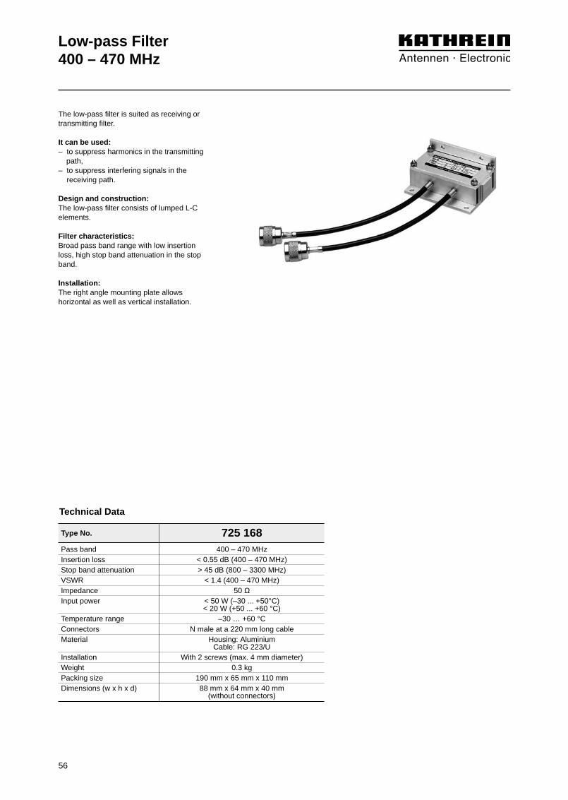
56
Type No. 725 168
Low-pass Filter400 – 470 MHz
Pass band 400 – 470 MHzInsertion loss < 0.55 dB (400 – 470 MHz)Stop band attenuation > 45 dB (800 – 3300 MHz)VSWR < 1.4 (400 – 470 MHz)Impedance 50 ΩInput power < 50 W (–30 ... +50°C)
< 20 W (+50 ... +60 °C)Temperature range –30 … +60 °CConnectors N male at a 220 mm long cableMaterial Housing: Aluminium
Cable: RG 223/UInstallation With 2 screws (max. 4 mm diameter)Weight 0.3 kgPacking size 190 mm x 65 mm x 110 mmDimensions (w x h x d) 88 mm x 64 mm x 40 mm
(without connectors)
Technical Data
The low-pass filter is suited as receiving ortransmitting filter.
It can be used:– to suppress harmonics in the transmitting
path,– to suppress interfering signals in the
receiving path.
Design and construction:The low-pass filter consists of lumped L-Celements.
Filter characteristics: Broad pass band range with low insertionloss, high stop band attenuation in the stopband.
Installation:The right angle mounting plate allowshorizontal as well as vertical installation.

57
Low-pass Filter400 – 470 MHzTypical attenuation curves
0
5
10
15
20
25
30
35
40
45
50
400 450 500 550 600 650 700 750 800 850 900
Atte
nuat
ion/
dB
Frequency/MHz
0
0.1
0.2
0.3
0.4
0.5
0.6
0.7
0.8
0.9
1.0
400 410 420 430 440 450 460 470 480 490 500
Atte
nuat
ion/
dB
Frequency/MHz
Diagram II:
Diagram I:
Detail seediagram II

58

59
Duplexers68 ... 87.5 MHz146 ... 174 MHz380 ... 470 MHz
Du
ple
xers

60

Summary of Articles
Duplexers:
61
Description Type No. Frequency range Max. input power Page... tunable bandwidth– fixed bandwidth (not tunable)
Duplexer 793 356 68 ... 87.5 MHz 15 W 62
Duplexer 718 987 68 ... 87.5 MHz 100 W 64
Duplexer 719 069 68 ... 87.5 MHz 100 W 64
Duplexer 720 209 68 ... 87.5 MHz 100 W 66
Duplexer 719 084 68 ... 87.5 MHz 100 W 66
Duplexer K 64 41 43 68 ... 87.5 MHz 200 W 68
Duplexer K 64 41 44 68 ... 87.5 MHz 200 W 68
Duplexer 793 357 146 ... 174 MHz 15 W 70
Duplexer 719 628 146 ... 174 MHz 100 W 72
Duplexer 718 388 146 ... 174 MHz 100 W 72
Duplexer 720 642 146 ... 174 MHz 100 W 74
Duplexer 720 877 146 ... 174 MHz 100 W 74
Duplexer 792 978 146 ... 164 MHz 300 W 76
Duplexer 792 979 156 ... 174 MHz 100 W 76
Duplexer K 64 41 23 146 ... 174 MHz 200 W 78
Duplexer K 64 41 24 146 ... 174 MHz 200 W 78
Duplexer 791 255 380 ... 470 MHz 15 W 80
Duplexer 719 785 380 ... 470 MHz 100 W 82
Duplexer 718 290 380 ... 470 MHz 100 W 82
Duplexer 718 313 380 ... 470 MHz 100 W 84
Duplexer 719 237 380 ... 470 MHz 100 W 84
Duplexer (TETRA, TETRAPOL) 782 10361 380 – 395 MHz 200 W 86
Duplexer (TETRA, TETRAPOL) 782 10362 382 – 397 MHz 200 W 86
Duplexer (TETRA, TETRAPOL) 782 10363 385 – 400 MHz 200 W 86
Duplexer (TETRA, TETRAPOL) 782 10371 380 – 395 MHz 200 W 86
Duplexer (TETRA, TETRAPOL) 782 10372 382 – 397 MHz 200 W 86
Duplexer (TETRA, TETRAPOL) 782 10373 385 – 400 MHz 200 W 86
Duplexer (TETRA, TETRAPOL) 782 10364 410 – 425 MHz 200 W 88
Duplexer (TETRA, TETRAPOL) 782 10365 415 – 430 MHz 200 W 88
Duplexer (TETRA, TETRAPOL) 782 10374 410 – 425 MHz 200 W 88
Duplexer (TETRA, TETRAPOL) 782 10375 415 – 430 MHz 200 W 88
Duplexer (TETRA, TETRAPOL) 782 10366 450 – 465 MHz 200 W 90
Duplexer (TETRA, TETRAPOL) 782 10367 455 – 470 MHz 200 W 90
Duplexer (TETRA, TETRAPOL) 782 10376 450 – 465 MHz 200 W 90
Duplexer (TETRA, TETRAPOL) 782 10377 455 – 470 MHz 200 W 90
Duplexer (4 Resonators) K 65 41 25 380 ... 470 MHz 200 W 92
Duplexer (6 Resonators) K 65 41 26 380 ... 470 MHz 200 W 92

Type No. 793 356
Duplexer68 … 87.5 MHz
Frequency range 68 … 87.5 MHzDuplex spacing 9.8 MHzSwitching bandwidth < 1.0 MHzInsertion loss 1) < 1.2 dB (at 1 MHz switching bandwidth)Isolation 2) > 65 dB (at 1 MHz switching bandwidth)VSWR < 1.4 (at operating frequency)Impedance 50 ΩInput power 3) < 15 WTemperature range –20 … +50 °CConnectors SMB male, angledMaterial Brass, silver-platedInstallation With 3 screws (max. 3 mm diameter)Weight 0.25 kgPacking size 150 mm x 30 mm x 120 mmDimensions (w x h x d) 144 mm x 20 mm x 114 mm
(with connectors)
1)Low band → Antenna / High band → Antenna
2)Low band ↔ High band
3)Low band or High band
Technical Data
The duplexer is suited to combine onetransmitter with one or several receivers toa common antenna.
Design and construction:The duplexer consists of a 4-cavity S-Pfilter (Stop-Pass filter) for the low band anda 4-cavity S-P filter for the high band. The S-P filters are designed to allow thetransmitter to operate in the low band or in the high band.
Tuning:The duplexer is tunable within the specifiedfrequency range.When ordering please note the desired lowand high band frequencies.The duplexer can be tuned on site usingthe instructions available on request.
62

Duplexer68 … 87.5 MHzTypical attenuation curves
0
10
20
30
40
50
60
70
80
90
100
68 70 72 74 76 78 80 82 84 86 88
Atte
nuat
ion/
dB
Frequency/MHz
0
0.5
1.0
1.5
2.0
2.5
3.0
3.5
4.0
4.5
5.0
68 69 70 71 72 73 74 75 76 77 78
Atte
nuat
ion/
dB
Frequency/MHz
0
0.5
1.0
1.5
2.0
2.5
3.0
3.5
4.0
4.5
5.0
78 79 80 81 82 83 84 85 86 87 88
Atte
nuat
ion/
dB
Frequency/MHz
Diagram III: (High band ↔ antenna)
Diagram II: (Low band ↔ antenna)
Diagram I:
Tuning example:
Duplex spacing: 9.8 MHz
Detail seediagram II
Detail seediagram III
63

Duplexer68 … 87.5 MHz
The duplexer is suited to combine onetransmitter with one or several receivers to a common antenna.
Design and construction:The duplexer consists of a 3-cavity or 4-cavity S-P filter (Stop-Pass filter) for thelow band and a 3-cavity or 4-cavity S-Pfilter for the high band. The two S-P filtersare interconnected to a common antennaoutput using cables of defined electricallengths.
The S-P filters are designed to allow thetransmitter to operate in the low band or in the high band.
Tuning:The duplexer, because of its special con-struction can only be tuned at the factory.Special requests like other duplex spac-ings, switching bandwidths or attenuationvalues can be taken into account.
When ordering please specify the desiredhigh and low band frequencies.
718 987
Technical Data
Type No. 718 987 719 069Number of resonators 3 + 3 4 + 4Frequency range 68 … 87.5 MHz
Tuning examplesDuplex spacing 3 MHz 6 MHz 9.8 MHz 2 MHz 6 MHz 9.8 MHzSwitching bandwidth 0.1 MHz 0.5 MHz 1.0 MHz 1.5 MHz 2.5 MHz 0.1 MHz * 1.0 MHz 2.5 MHz 3.3 MHz 4.0 MHzInsertion loss 1) < 1.5 dB < 0.8 dB < 0.8 dB < 0.8 dB < 1.0 dB < 1.8 dB < 1.0 dB < 1.0 dB < 1.0 dB < 1.2 dBIsolation 2) > 65 dB > 70 dB > 75 dB > 70 dB > 65 dB > 65 dB > 75 dB > 80 dB > 70 dB > 65 dBVSWR < 1.4 (at operating frequency)Impedance 50 ΩInput power 3) < 100 W (–30 … +55 °C) / < 50 W (+55 … +70 °C)
* < 50 W (–30 … +55 °C) / < 30 W (+55 … +70 °C)Temperature range –30 … +70 °CConnectors N femaleMaterial S-P resonators: Aluminium / copper, silver-plated; cable: RG 223/UInstallation With 4 screws (max. 4 mm diameter)Weight 2.15 kg 2.75 kgPacking size 275 mm x 60 mm x 245 mm 362 mm x 60 mm x 245 mmDimensions (w x h x d) 263 mm x 50 mm x 190 mm 350 mm x 50 mm x 190 mm
(with connectors) (with connectors)
1) Low band ↔ Antenna / High band ↔ Antenna2) Low band ↔ High band3) Low band or High band
719 069
64

Duplexer68 … 87.5 MHzTypical attenuation curves
A: Low band ↔ antennaB: High band ↔ antenna
Duplexer 718 987 Duplexer 719 069Duplex spacing: 6.0 MHz
Switching bandwidth: 0.5 MHzDuplex spacing: 6.0 MHz
Switching bandwidth: 1.0 MHz
Tuning examples:
Duplex spacing: 9.8 MHzSwitching bandwidth: 1.0 MHz
Duplex spacing: 9.8 MHzSwitching bandwidth: 2.5 MHz
Duplex spacing: 9.8 MHzSwitching bandwidth: 2.5 MHz
Duplex spacing: 9.8 MHzSwitching bandwidth: 4.0 MHz
0
10
20
30
40
50
60
70
80
90
100
68 70 72 74 76 78 80 82 84 86 88
Atte
nuat
ion/
dB
Frequency/MHz
0
10
20
30
40
50
60
70
80
90
100
68 70 72 74 76 78 80 82 84 86 88
Atte
nuat
ion/
dB
Frequency/MHz
0
10
20
30
40
50
60
70
80
90
100
68 70 72 74 76 78 80 82 84 86 88
Atte
nuat
ion/
dB
Frequency/MHz
0
10
20
30
40
50
60
70
80
90
100
68 70 72 74 76 78 80 82 84 86 88
Atte
nuat
ion/
dB
Frequency/MHz
0
10
20
30
40
50
60
70
80
90
100
68 70 72 74 76 78 80 82 84 86 88
Atte
nuat
ion/
dB
Frequency/MHz
0
10
20
30
40
50
60
70
80
90
100
68 70 72 74 76 78 80 82 84 86 88
Atte
nuat
ion/
dB
Frequency/MHz
A B
A B
A B
A B
A B
A B
65

66
Duplexer68 … 87.5 MHz
720 209
Technical Data
Number of resonators 3 + 3 4 + 4Frequency range 68 … 87.5 MHz
Tuning examplesDuplex spacing 3 MHz 6 MHz 9.8 MHz 2 MHz 6 MHz 9.8 MHzSwitching bandwidth 0.1 MHz 0.5 MHz 1.0 MHz 1.5 MHz 2.5 MHz 0.1 MHz * 1.0 MHz 2.5 MHz 3.3 MHz 4.0 MHzInsertion loss 1) < 1.5 dB < 0.8 dB < 0.8 dB < 0.8 dB < 1.0 dB < 1.8 dB < 1.0 dB < 1.0 dB < 1.0 dB < 1.2 dBIsolation 2) > 65 dB > 70 dB > 75 dB > 70 dB > 65 dB > 65 dB > 75 dB > 80 dB > 70 dB > 65 dBVSWR < 1.4 (at operating frequency)Impedance 50 ΩInput power 3) < 100 W (–30 … +55 °C) / < 50 W (+55 … +70 °C)
* < 50 W (–30 … +55 °C) / < 30 W (+55 … +70 °C)Temperature range –30 … +70 °CConnectors N female, silver-platedMaterial S-P resonators: Brass, silver-plated / copper, silver-plated; cable: RG 223/UInstallation With 4 screws (max. 5 mm diameter)Weight 3.0 kg 3.5 kgPacking size 275 mm x 60 mm x 245 mm 355 mm x 60 mm x 245 mmDimensions (w x h x d) 270 mm x 58 mm x 190 mm 350 mm x 58 mm x 190 mm
(with connectors) (with connectors)
1) Low band ↔ Antenna / High band ↔ Antenna2) Low band ↔ High band3) Input power low band or high band respectively the summ of the input powers low band and high band.
719 084
Type No. 720 209 719 084
The duplexer is suited to combine one orseveral transmitters with one or severalreceivers to a common antenna.It can also be used to combine two trans-mitters to a common transmitting antenna.
Design and construction:The duplexer consists of a 3-cavity or 4-cavity S-P filter (Stop-Pass filter) for the lowband and a 3-cavity or 4-cavity S-P filter forthe high band. The two S-P filters are inter-connected to a common antenna outputusing cables of defined electrical lengths.
The S-P filters are designed to allow thetransmitters to be operated in either the lowband or the high band or in both bandstogether.
Tuning:The duplexer, because of its special con-struction can only be tuned at the factory.Special requests like other duplex spac-ings, switching bandwidths or attenuationvalues can be taken into account.
When ordering please specify the desiredhigh and low band frequencies.
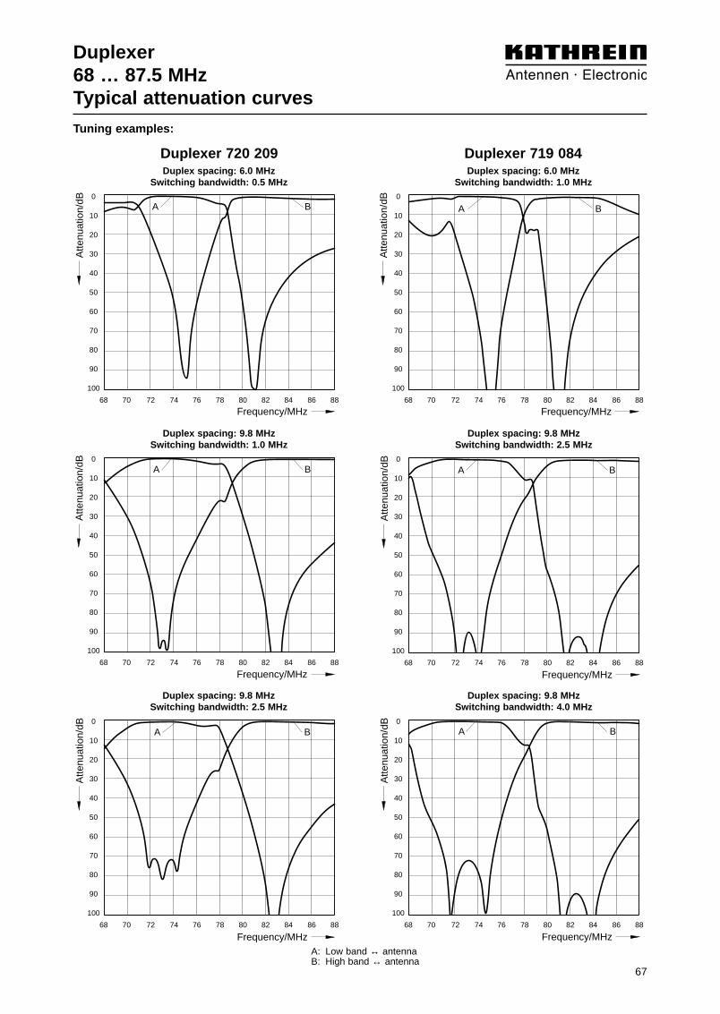
Duplexer68 … 87.5 MHzTypical attenuation curves
Duplexer 720 209 Duplexer 719 084
Tuning examples:
A: Low band ↔ antennaB: High band ↔ antenna
Duplex spacing: 6.0 MHzSwitching bandwidth: 0.5 MHz
Duplex spacing: 6.0 MHzSwitching bandwidth: 1.0 MHz
Duplex spacing: 9.8 MHzSwitching bandwidth: 1.0 MHz
Duplex spacing: 9.8 MHzSwitching bandwidth: 2.5 MHz
Duplex spacing: 9.8 MHzSwitching bandwidth: 2.5 MHz
Duplex spacing: 9.8 MHzSwitching bandwidth: 4.0 MHz
0
10
20
30
40
50
60
70
80
90
100
68 70 72 74 76 78 80 82 84 86 88
Atte
nuat
ion/
dB
Frequency/MHz
0
10
20
30
40
50
60
70
80
90
100
68 70 72 74 76 78 80 82 84 86 88
Atte
nuat
ion/
dB
Frequency/MHz
0
10
20
30
40
50
60
70
80
90
100
68 70 72 74 76 78 80 82 84 86 88
Atte
nuat
ion/
dB
Frequency/MHz
0
10
20
30
40
50
60
70
80
90
100
68 70 72 74 76 78 80 82 84 86 88
Atte
nuat
ion/
dB
Frequency/MHz
0
10
20
30
40
50
60
70
80
90
100
68 70 72 74 76 78 80 82 84 86 88
Atte
nuat
ion/
dB
Frequency/MHz
0
10
20
30
40
50
60
70
80
90
100
68 70 72 74 76 78 80 82 84 86 88
Atte
nuat
ion/
dB
Frequency/MHz
A B
A B
A B
A B
A B
A B
67
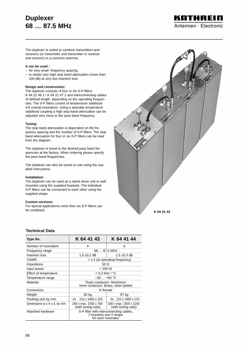
Duplexer68 … 87.5 MHz
The duplexer is suited to combine transmitters andreceivers (or transmitter and transmitter or receiver and receiver) to a common antenna.
It can be used :– for very small frequency spacing,– to obtain very high stop band attenuation (more than
100 dB) at very low insertion loss.
Design and construction:The duplexer consists of four or six S-P filters K 64 21 46 1 / K 64 21 47 1 and interconnecting cablesof defined length, depending on the operating frequen-cies. The S-P filters consist of temperature stabilizedλ/4 coaxial resonators. Using a specially temperaturestabilized coupling a high stop band attenuation can beadjusted very close to the pass band frequency.
Tuning:The stop band attenuation is dependent on the fre-quency spacing and the number of S-P filters. The stopband attenuation for four or six S-P filters can be readfrom the diagram.
The duplexer is tuned to the desired pass band fre-quencies at the factory. When ordering please specifythe pass band frequencies.
The duplexer can also be tuned on site using the sup-plied instructions.
Installation:The duplexer can be used as a stand alone unit or wallmounted using the supplied brackets. The individual S-P filters can be connected to each other using thesupplied straps.
Custom versions:For special applications more than six S-P filters canbe combined.
Number of resonators 4 6Frequency range 68 … 87.5 MHzInsertion loss 1.0 ±0.2 dB 1.5 ±0.3 dBVSWR < 1.4 (at operating frequency)Impedance 50 ΩInput power < 200 WEffect of temperature < 0.2 kHz / °CTemperature range –30 … +60 °CMaterial Outer conductor: Aluminium
Inner conductor: Brass, silver-platedConnectors N femaleWeight 65 kg 97 kgPacking size by mm 4x 210 x 1660 x 210 6x 210 x 1660 x 210Dimensions w x h x d, by mm 190 x max. 1500 x 760 190 x max. 1500 x 1140
(with tuning rods) (with tuning rods)Attached hardware S-P filter with interconnecting cables,
2 brackets and 2 strapsfor each resonator
Type No. K 64 41 43 K 64 41 44
Technical Data
K 64 41 43
68

Duplexer68 … 68.5 MHzTypical attenuation curves
4 1 1.0 dB K 64 41 436 2 1.5 dB K 64 41 44
120
110
100
90
80
70
60
0.2 0.4 0.6 0.8 1.0
1
2
Sto
p ba
ndat
tenu
atio
n/dB
Frequency spacing between pass band frequencyand stop band frequency/MHz
Number of InsertionCurve Type No.resonators loss
69

70
Type No. 793 357
Duplexer146 … 174 MHz
Frequency range 146 … 174 MHzDuplex spacing 4.6 MHzSwitching bandwidth < 1.0 MHzInsertion loss 1) < 2.0 dB (at 1 MHz switching bandwidth)Isolation 2) > 65 dB (at 1 MHz switching bandwidth)VSWR < 1.4 (at operating frequency)Impedance 50 ΩInput power 3) < 15 WTemperature range –20 … +50 °CConnectors SMB male, angledMaterial Brass, silver-platedInstallation With 3 screws (max. 3 mm diameter)Weight 0.25 kgPacking size 150 mm x 30 mm x 120 mmDimensions (w x h x d) 144 mm x 20 mm x 114 mm
(with connectors)
1) Low band ↔ Antenna / High band ↔ Antenna2) Low band ↔ High band3)
Low band or High band
Technical Data
The duplexer is suited to combine onetransmitter with one or several receivers to a common antenna.
Design and construction:The duplexer consists of a 4-cavity S-Pfilter (Stop-Pass filter) for the low band and a 4-cavity S-P filter for the high band.The S-P filters are designed to allow thetransmitter to operate in the low band or in the high band.
Tuning:The duplexer is tunable within the specifiedfrequency range.When ordering please note the desired lowand high band frequencies.The duplexer can be tuned on site usingthe instructions available on request.
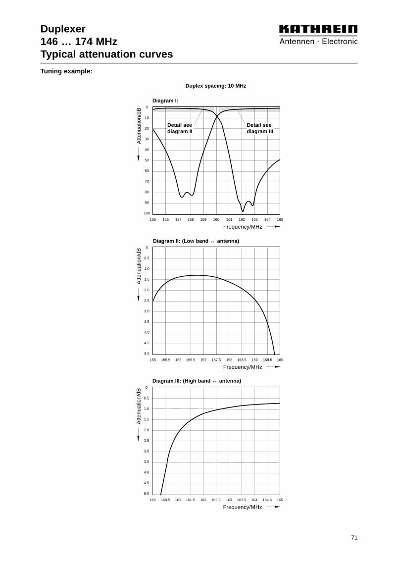
71
Duplexer146 … 174 MHzTypical attenuation curves
0
10
20
30
40
50
60
70
80
90
100
155 156 157 158 159 160 161 162 163 164 165
Atte
nuat
ion/
dB
Frequency/MHz
0
0.5
1.0
1.5
2.0
2.5
3.0
3.5
4.0
4.5
5.0
155 155.5 156 156.5 157 157.5 158 158.5 159 159.5 160
Atte
nuat
ion/
dB
Frequency/MHz
0
0.5
1.0
1.5
2.0
2.5
3.0
3.5
4.0
4.5
5.0
160 160.5 161 161.5 162 162.5 163 163.5 164 164.5 165
Atte
nuat
ion/
dB
Frequency/MHz
Diagram III: (High band ↔ antenna)
Diagram II: (Low band ↔ antenna)
Diagram I:
Tuning example:
Duplex spacing: 10 MHz
Detail seediagram II
Detail seediagram III

72
Duplexer146 … 174 MHz
The duplexer is suited to combine onetransmitter with one or several receivers to a common antenna.
Design and construction:The duplexer consists of a 3-cavity or 4-cavity S-P filter (Stop-Pass filter) for thelow band and a 3-cavity or 4-cavity S-Pfilter for the high band. The two S-P filtersare interconnected to a common antennaoutput using cables of defined electricallengths.
The S-P filters are designed to allow thetransmitter to operate in the low band or in the high band.
Tuning:The duplexer, because of its special con-struction can only be tuned at the factory.Special requests like other duplex spa-cings, switching bandwidths or attenuationvalues can be taken into account.
When ordering please specify the desiredhigh and low band frequencies.
718 388
Technical Data
Type No. 719 628 718 388Number of resonators 3 + 3 4 + 4Frequency range 146 … 174 MHz
Tuning examplesDuplex spacing 3.5 MHz 4.6 MHz 6 MHz 3 MHz 4.6 MHz 6 MHzSwitching bandwidth 0.1 MHz 0.1 MHz 0.5 MHz 1.0 MHz 1.0 MHz 0.1 MHz * 0.5 MHz 1.0 MHz * 1.9 MHz * 2.0 MHzInsertion loss 1) < 1.5 dB < 1.0 dB < 1.2 dB < 1.3 dB < 1.2 dB < 1.6 dB < 1.5 dB < 1.6 dB < 2.3 dB < 1.5 dBIsolation 2) > 65 dB > 75 dB > 65 dB > 60 dB > 65 dB > 70 dB > 75 dB > 65 dB > 60 dB > 65 dBVSWR < 1.4 (at operating frequency)Impedance 50 ΩInput power 3) < 100 W (–30 … +55 °C) / < 50 W (+55 … +70 °C)
* < 50 W (–30 … +55 °C) / < 30 W (+55 … +70 °C)Temperature range –30 … +70 °CConnectors N femaleMaterial S-P resonators: Aluminium / copper, silver-plated; cable: RG 223/UInstallation With 4 screws (max. 4 mm diameter)Weight 2.1 kg 2.75 kgPacking size 275 mm x 60 mm x 245 mm 360 mm x 60 mm x 245 mmDimensions (w x h x d) 263 mm x 50 mm x 170 mm 350 mm x 50 mm x 170 mm
(with connectors) (with connectors)
1) Low band ↔ Antenna / High band ↔ Antenna2) Low band ↔ High band3) Low band or High band
719 628

73
Duplexer146 … 174 MHzTypical attenuation curves
A: Low band ↔ antennaB: High band ↔ antenna
Duplexer 719 628 Duplexer 718 388Duplex spacing: 4.6 MHz
Switching bandwidth: 0.1 MHzDuplex spacing: 4.6 MHz
Switching bandwidth: 0.5 MHz
Duplex spacing: 4.6 MHzSwitching bandwidth: 1.0 MHz
Duplex spacing: 4.6 MHzSwitching bandwidth: 1.9 MHz
Duplex spacing: 6.0 MHzSwitching bandwidth: 1.0 MHz
Duplex spacing: 6.0 MHzSwitching bandwidth: 2.0 MHz
Tuning examples:
0
10
20
30
40
50
60
70
80
90
100
155 156 157 158 159 160 161 162 163 164 165
Atte
nuat
ion/
dB
Frequency/MHz
0
10
20
30
40
50
60
70
80
90
100
155 156 157 158 159 160 161 162 163 164 165
Atte
nuat
ion/
dB
Frequency/MHz
0
10
20
30
40
50
60
70
80
90
100
155 156 157 158 159 160 161 162 163 164 165
Atte
nuat
ion/
dB
Frequency/MHz
0
10
20
30
40
50
60
70
80
90
100
155 156 157 158 159 160 161 162 163 164 165
Atte
nuat
ion/
dB
Frequency/MHz
0
10
20
30
40
50
60
70
80
90
100
155 156 157 158 159 160 161 162 163 164 165
Atte
nuat
ion/
dB
Frequency/MHz
0
10
20
30
40
50
60
70
80
90
100
155 156 157 158 159 160 161 162 163 164 165
Atte
nuat
ion/
dB
Frequency/MHz
A B A B
A BA B
A B A B

74
Duplexer146 … 174 MHz
The duplexer is suited to combine one orseveral transmitters with one or severalreceivers to a common antenna.
It can also be used to combine two trans-mitters to a common transmitting antenna.
Design and construction:The duplexer consists of a 3-cavity or 4-cavity S-P filter (Stop-Pass filter) for thelow band and a 3-cavity or 4-cavity S-Pfilter for the high band. The two S-P filtersare interconnected to a common antennaoutput using cables of defined electricallengths.
The S-P filters are designed to allow thetransmitters to be operated in either the low band or the high band or in both bandstogether.
Tuning:The duplexer, because of its special con-struction can only be tuned at the factory.Special requests like other duplex spa-cings, switching bandwidths or attenuationvalues can be taken into account.
When ordering please specify the desiredhigh and low band frequencies.
720 642
Technical Data
Type No. 720 642 720 877Number of resonators 3 + 3 4 + 4Frequency range 146 … 174 MHz
Tuning examplesDuplex spacing 3.5 MHz 4.6 MHz 6 MHz 3 MHz 4.6 MHz 6 MHzSwitching bandwidth 0.1 MHz 0.1 MHz 0.5 MHz 1.0 MHz 1.0 MHz 0.1 MHz * 0.5 MHz 1.0 MHz * 1.9 MHz * 2.0 MHzInsertion loss 1) < 1.5 dB < 1.0 dB < 1.2 dB < 1.3 dB < 1.2 dB < 1.6 dB < 1.5 dB < 1.6 dB < 2.3 dB < 1.5 dBIsolation 2) > 65 dB > 75 dB > 65 dB > 60 dB > 65 dB > 70 dB > 75 dB > 65 dB > 60 dB > 65 dBVSWR < 1.4 (at operating frequency)Impedance 50 ΩInput power 3) < 100 W (–30 … +55 °C) / < 50 W (+55 … +70 °C)
* < 50 W (–30 … +55 °C) / < 30 W (+55 … +70 °C)Temperature range –30 … +70 °CConnectors N female, silver-platedMaterial S-P resonators: Brass, silver-plated / copper, silver-plated; cable: RG 223/UInstallation With 4 screws (max. 5 mm diameter)Weight 3.0 kg 3.5 kgPacking size 450 mm x 130 mm x 330 mm 530 mm x 130 mm x 330 mmDimensions (w x h x d) 270 mm x 58 mm x 190 mm 350 mm x 58 mm x 190 mm
(with connectors) (with connectors)
1) Low band ↔ Antenna / High band ↔ Antenna2) Low band ↔ High band3) Input power low band or high band respectively the summ of the input powers low band and high band.
720 877

75
Duplexer146 … 174 MHzTypical attenuation curves
Tuning examples:
A: Low band ↔ antennaB: High band ↔ antenna
Duplexer 720 642 Duplexer 720 877Duplex spacing: 4.6 MHz
Switching bandwidth: 0.1 MHzDuplex spacing: 4.6 MHz
Switching bandwidth: 0.5 MHz
Duplex spacing: 4.6 MHzSwitching bandwidth: 1.0 MHz
Duplex spacing: 4.6 MHzSwitching bandwidth: 1.9 MHz
Duplex spacing: 6.0 MHzSwitching bandwidth: 1.0 MHz
Duplex spacing: 6.0 MHzSwitching bandwidth: 2.0 MHz
0
10
20
30
40
50
60
70
80
90
100
155 156 157 158 159 160 161 162 163 164 165
Atte
nuat
ion/
dB
Frequency/MHz
0
10
20
30
40
50
60
70
80
90
100
155 156 157 158 159 160 161 162 163 164 165
Atte
nuat
ion/
dB
Frequency/MHz
0
10
20
30
40
50
60
70
80
90
100
155 156 157 158 159 160 161 162 163 164 165
Atte
nuat
ion/
dB
Frequency/MHz
0
10
20
30
40
50
60
70
80
90
100
155 156 157 158 159 160 161 162 163 164 165
Atte
nuat
ion/
dB
Frequency/MHz
0
10
20
30
40
50
60
70
80
90
100
155 156 157 158 159 160 161 162 163 164 165
Atte
nuat
ion/
dB
Frequency/MHz
0
10
20
30
40
50
60
70
80
90
100
155 156 157 158 159 160 161 162 163 164 165
Atte
nuat
ion/
dB
Frequency/MHz
A B A B
A BA B
A B A B

76
Duplexer146 ... 174 MHz
The duplexer is suited to combine one orseveral transmitters with one or severalreceivers to a common antenna. It can alsobe used to combine two transmitters to acommon transmitting antenna.
Design and construction:The duplexer consists of a 4-cavity S-Pfilter (Stop-Pass filter) for the low band anda 4-cavity S-P filter for the high band. The S-P filters are designed to allow thetransmitters to be operated in either the low band or the high band or in both bandstogether.
Tuning:The duplexer is tuned to the desired passband frequencies at the factory. Special re-quests like other duplex spacings, switchingbandwidths or attenuation values can betaken into account.
When ordering please specify the desiredhigh and low band frequencies.
Tuning examplesDuplex spacing 4.6 MHz 1.5 MHzSwitching bandwidth < 1.5 MHz < 0.05 MHz < 0.5 MHz < 0.05 MHzInsertion loss < 1.0 dB < 0.7 dB < 2.0 dB < 1.5 dBIsolation > 80 dB > 90 dB > 60 dB > 65 dBVSWR < 1.4 (at operating frequency)Impedance 50 ΩInput power 1) < 300 W < 100 WTemperature range –20 … +50 °CMaterial Duplexer: Brass, silver-plated and varnished (RAL 7032)
Drawer: Aluminium Front panel: Aluminium, varnished, grey (RAL 7032)
Connectors N female, silver-platedWeight 6.7 kgPacking size 540 mm x 192 mm x 520 mm 540 mm x 192 mm x 520 mmDimensions 19˝ drawer with 2 height units with a plug-in depth of 380 mm
1) Input power low band or high band or the summ of the input powers low band andhigh band.
Type No. 792 978: Frequency range 146 ... 164 MHz
792 979: Frequency range 156 ... 174 MHz
Technical Data
792 978792 979

77
0
10
20
30
40
50
60
70
80
90
100
160 161 162 163 164 165 166 167 168 169 170
Atte
nuat
ion/
dB
Frequency/MHz
Duplexer146 ... 174 MHzTypical attenuation curves
Diagram II: Low band ↔ antenna High band ↔ antenna
792 979Duplex spacing: 4.6 MHz
Switching bandwidth: 1.5 MHzDiagram I:
Low band ↔ antenna High band ↔ antenna
Tuning example:
0
0.5
1.0
1.5
2.0
2.5
3.0
3.5
4.0
4.5
5.0
160 161 162 163 164 165 166 167 168 169 170
Atte
nuat
ion/
dB
Frequency/MHz
Detail seediagram II

78
Duplexer146 … 174 MHz
The duplexer is suited to combine transmitters andreceivers (or transmitter and transmitter or receiverand receiver) to a common antenna.
It can be used :– for very small frequency spacing,– to obtain very high stop band attenuation (more
than 100 dB) at very low insertion loss.
Design and construction:The duplexer consists of four or six S-P filters K 64 21 26 1 and interconnecting cables of definedlength, depending on the operating frequencies.The S-P filters consist of temperature stabilized λ/4 coaxial resonators. Using a specially tempera-ture stabilized coupling a high stop band attenu-ation can be adjusted very close to the pass bandfrequency.
Tuning:The stop band attenuation is dependent on the frequency spacing and the number of S-P filters.The stop band attenuation for four or six S-P filterscan be read from the diagram.
The duplexer is tuned to the desired pass band frequencies at the factory. When ordering pleasespecify the pass band frequencies.
The duplexer can also be tuned on site using thesupplied instructions.
Installation:The duplexer can be used as a stand alone unit orwall mounted using the supplied brackets. The indi-vidual S-P filters can be connected to each otherusing the supplied straps.
Custom versions:For special applications more than six S-P filterscan be combined.
K 64 41 23
Number of resonators 4 6Frequency range 146 … 174 MHzInsertion loss 1.0 ±0.2 dB 1.5 dB ±0.3 dBVSWR < 1.4 (at operating frequency)Impedance 50 ΩInput power < 200 WEffect of temperature < 0.4 kHz / °CTemperature range –30 … +60 °CMaterial Outer conductor: Aluminium
Inner conductor: Brass, silver-platedConnectors N femaleWeight 36.5 kg 54.5 kgPacking size 4x 210 mm x 865 mm x 210 mm 6x 210 mm x 865 mm x 210 mm Dimensions (w x h x d) 190 mm x max. 770 mm x 760 mm 190 mm x max. 770 mm x 1140 mm
(with tuning rods) (with tuning rods)Attached hardware S-P filter with interconnecting cables,
2 brackets and 2 straps for each resonator
Type No. K 64 41 23 K 64 41 24
Technical Data

79
Duplexer146 … 174 MHzTypical attenuation curves
120
110
100
90
80
70
60
0.2 0.6 1.0 1.4 1.8
2
1
Sto
p ba
ndat
tenu
atio
n/dB
Frequency spacing between pass band frequencyand stop band frequency/MHz
4 1 1.0 dB K 64 41 236 2 1.5 dB K 64 41 24
Number of InsertionCurve Type No.resonators loss
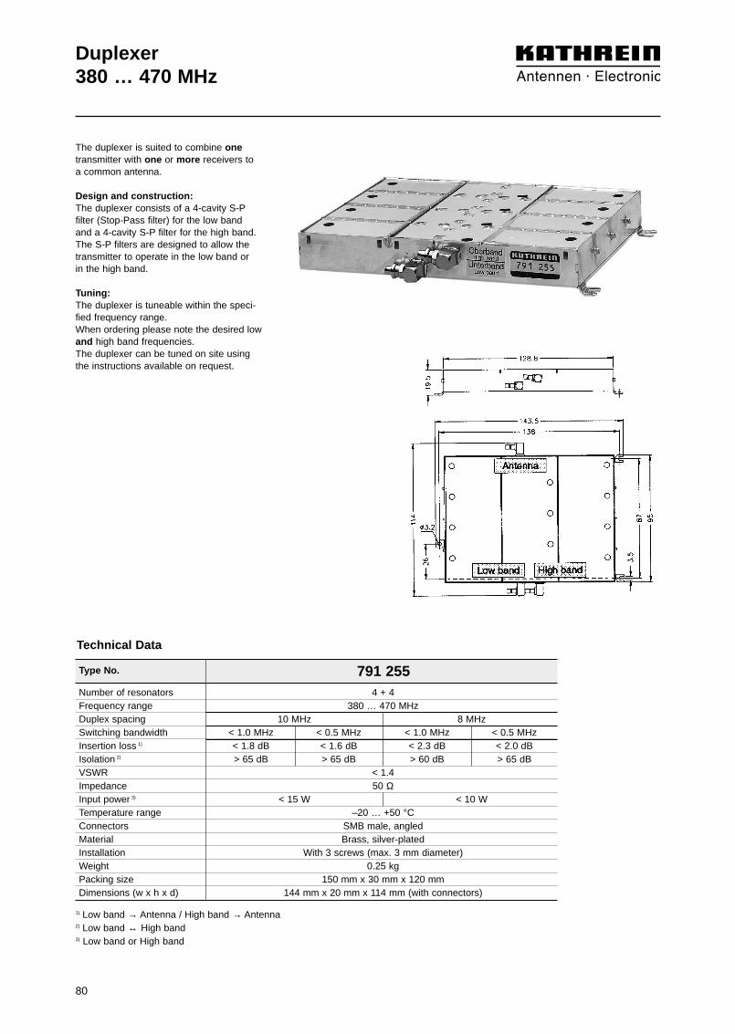
80
Type No. 791 255
Duplexer380 … 470 MHz
Number of resonators 4 + 4Frequency range 380 … 470 MHzDuplex spacing 10 MHz 8 MHzSwitching bandwidth < 1.0 MHz < 0.5 MHz < 1.0 MHz < 0.5 MHzInsertion loss 1) < 1.8 dB < 1.6 dB < 2.3 dB < 2.0 dBIsolation 2) > 65 dB > 65 dB > 60 dB > 65 dBVSWR < 1.4Impedance 50 ΩInput power 3) < 15 W < 10 WTemperature range –20 … +50 °CConnectors SMB male, angledMaterial Brass, silver-platedInstallation With 3 screws (max. 3 mm diameter)Weight 0.25 kgPacking size 150 mm x 30 mm x 120 mmDimensions (w x h x d) 144 mm x 20 mm x 114 mm (with connectors)
1) Low band → Antenna / High band → Antenna2) Low band ↔ High band3) Low band or High band
Technical Data
The duplexer is suited to combine onetransmitter with one or more receivers toa common antenna.
Design and construction:The duplexer consists of a 4-cavity S-Pfilter (Stop-Pass filter) for the low band and a 4-cavity S-P filter for the high band. The S-P filters are designed to allow thetransmitter to operate in the low band or in the high band.
Tuning:The duplexer is tuneable within the speci-fied frequency range.When ordering please note the desired lowand high band frequencies.The duplexer can be tuned on site usingthe instructions available on request.

81
Duplexer380 … 470 MHzTypical attenuation curves
Tuning examples:
0
10
20
30
40
50
60
70
80
90
100
425 427 429 431 433 435 437 439 441 443 445
Atte
nuat
ion/
dB
Frequency/MHz
425 426 427 428 429 430 431 432 433 434 435
0
1.0
2.0
3.0
4.0
5.0
0.5
1.5
2.5
3.5
4.5
Atte
nuat
ion/
dB
Frequency/MHz
435 436 437 438 439 440 441 442 443 444 445
0
1.0
2.0
3.0
4.0
5.0
0.5
1.5
2.5
3.5
4.5
Atte
nuat
ion/
dB
Frequency/MHz
Diagram II: (Low band → Antenna)
Diagram III: (High band → Antenna)
Diagram I:
Detail seediagram III
Detail seediagram II
Duplex spacing: 10 MHz
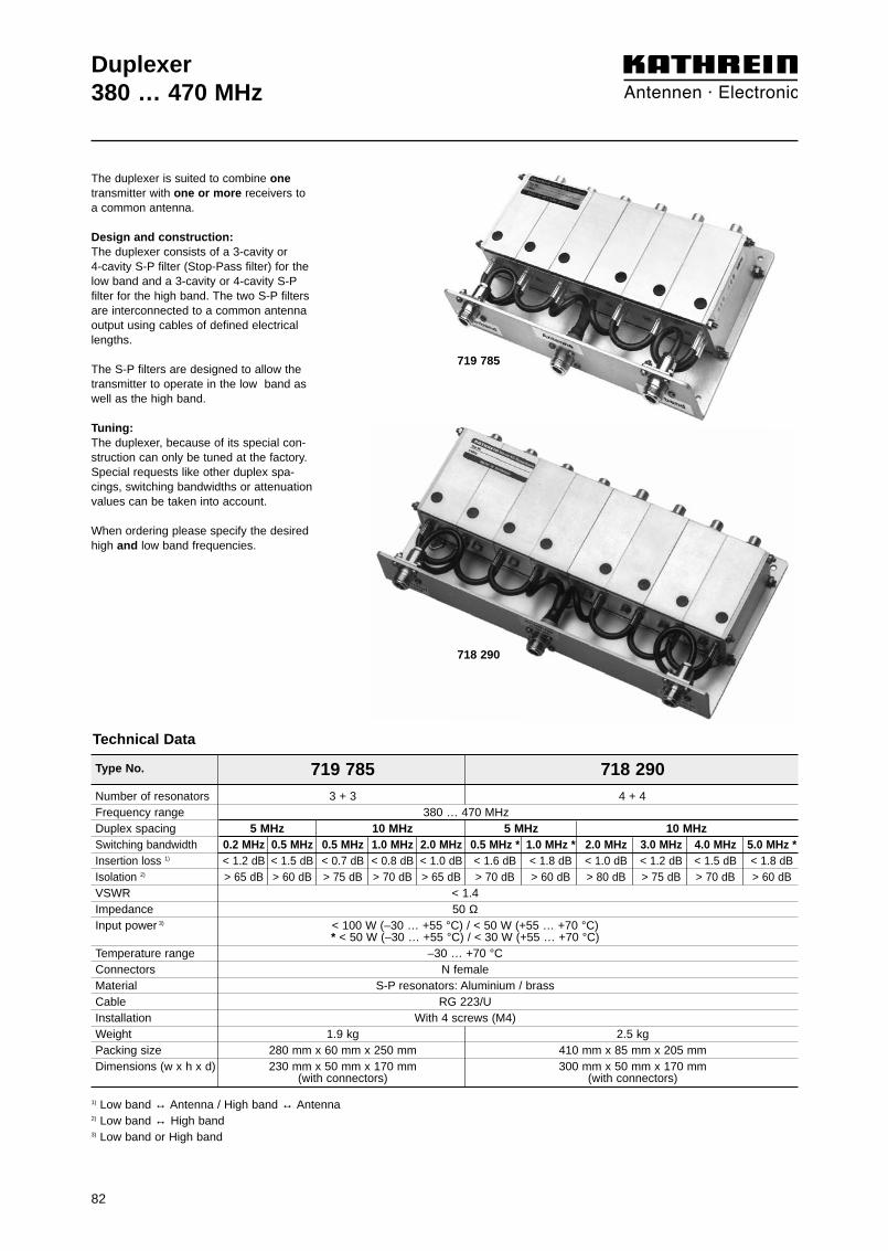
82
Duplexer380 … 470 MHz
Technical Data
The duplexer is suited to combine onetransmitter with one or more receivers to a common antenna.
Design and construction:The duplexer consists of a 3-cavity or 4-cavity S-P filter (Stop-Pass filter) for thelow band and a 3-cavity or 4-cavity S-Pfilter for the high band. The two S-P filtersare interconnected to a common antennaoutput using cables of defined electricallengths.
The S-P filters are designed to allow thetransmitter to operate in the low band aswell as the high band.
Tuning:The duplexer, because of its special con-struction can only be tuned at the factory.Special requests like other duplex spa-cings, switching bandwidths or attenuationvalues can be taken into account.
When ordering please specify the desiredhigh and low band frequencies.
719 785
718 290
Type No. 719 785 718 290Number of resonators 3 + 3 4 + 4Frequency range 380 … 470 MHzDuplex spacing 5 MHz 10 MHz 5 MHz 10 MHzSwitching bandwidth 0.2 MHz 0.5 MHz 0.5 MHz 1.0 MHz 2.0 MHz 0.5 MHz * 1.0 MHz * 2.0 MHz 3.0 MHz 4.0 MHz 5.0 MHz *Insertion loss 1) < 1.2 dB < 1.5 dB < 0.7 dB < 0.8 dB < 1.0 dB < 1.6 dB < 1.8 dB < 1.0 dB < 1.2 dB < 1.5 dB < 1.8 dBIsolation 2) > 65 dB > 60 dB > 75 dB > 70 dB > 65 dB > 70 dB > 60 dB > 80 dB > 75 dB > 70 dB > 60 dBVSWR < 1.4Impedance 50 ΩInput power 3) < 100 W (–30 … +55 °C) / < 50 W (+55 … +70 °C)
* < 50 W (–30 … +55 °C) / < 30 W (+55 … +70 °C)Temperature range –30 … +70 °CConnectors N femaleMaterial S-P resonators: Aluminium / brassCable RG 223/UInstallation With 4 screws (M4)Weight 1.9 kg 2.5 kgPacking size 280 mm x 60 mm x 250 mm 410 mm x 85 mm x 205 mmDimensions (w x h x d) 230 mm x 50 mm x 170 mm 300 mm x 50 mm x 170 mm
(with connectors) (with connectors)
1) Low band ↔ Antenna / High band ↔ Antenna2) Low band ↔ High band3) Low band or High band

83
Duplexer380 … 470 MHzTypical attenuation curves
A: Low band ↔ AntennaB: High band ↔ Antenna
0
10
20
30
40
50
60
70
80
90
100
425 427 429 431 433 435 437 439 441 443 445
Atte
nuat
ion/
dB
Frequency/MHz
A B0
10
20
30
40
50
60
70
80
90
100
425 427 429 431 433 435 437 439 441 443 445
A B
Atte
nuat
ion/
dB
Frequency/MHz
0
10
20
30
40
50
60
70
80
90
100
425 427 429 431 433 435 437 439 441 443 445
Atte
nuat
ion/
dB
Frequency/MHz
A B
0
10
20
30
40
50
60
70
80
90
100
425 427 429 431 433 435 437 439 441 443 445
Atte
nuat
ion/
dB
Frequency/MHz
A B
Duplexer 719 785 Duplexer 718 290
Duplex spacing : 5 MHzSwitching bandwidth: 0.5 MHz
Duplex spacing : 5 MHzSwitching bandwidth: 1.0 MHz
Duplex spacing : 10 MHzSwitching bandwidth: 1.0 MHz
Duplex spacing : 10 MHzSwitching bandwidth: 2.0 MHz
Duplex spacing : 10 MHzSwitching bandwidth: 2.0 MHz
Duplex spacing : 10 MHzSwitching bandwidth: 4.0 MHz
Tuning examples:
0
10
20
30
40
50
60
70
80
90
100
425 427 429 431 433 435 437 439 441 443 445
Atte
nuat
ion/
dB
Frequency/MHz
A B0
10
20
30
40
50
60
70
80
90
100
425 427 429 431 433 435 437 439 441 443 445
A B
Atte
nuat
ion/
dB
Frequency/MHz
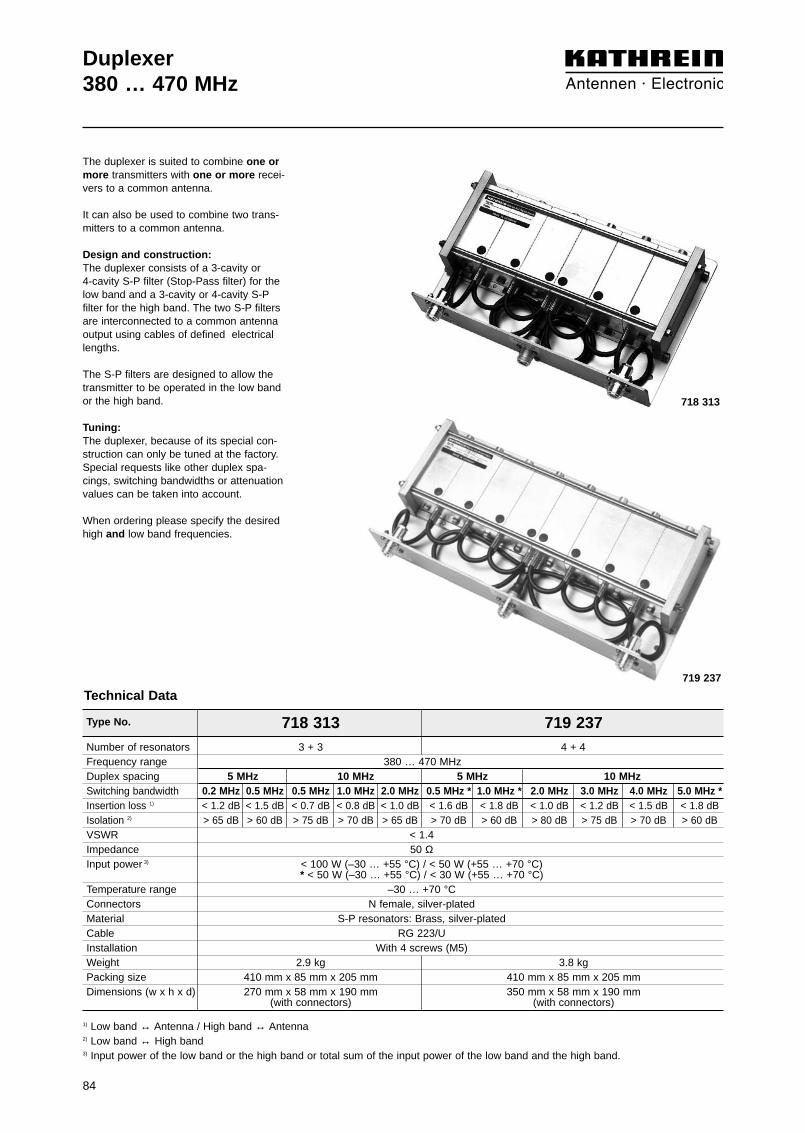
Technical Data
Type No. 718 313 719 237Number of resonators 3 + 3 4 + 4Frequency range 380 … 470 MHzDuplex spacing 5 MHz 10 MHz 5 MHz 10 MHzSwitching bandwidth 0.2 MHz 0.5 MHz 0.5 MHz 1.0 MHz 2.0 MHz 0.5 MHz * 1.0 MHz * 2.0 MHz 3.0 MHz 4.0 MHz 5.0 MHz *Insertion loss 1) < 1.2 dB < 1.5 dB < 0.7 dB < 0.8 dB < 1.0 dB < 1.6 dB < 1.8 dB < 1.0 dB < 1.2 dB < 1.5 dB < 1.8 dBIsolation 2) > 65 dB > 60 dB > 75 dB > 70 dB > 65 dB > 70 dB > 60 dB > 80 dB > 75 dB > 70 dB > 60 dBVSWR < 1.4Impedance 50 ΩInput power 3) < 100 W (–30 … +55 °C) / < 50 W (+55 … +70 °C)
* < 50 W (–30 … +55 °C) / < 30 W (+55 … +70 °C)Temperature range –30 … +70 °CConnectors N female, silver-platedMaterial S-P resonators: Brass, silver-platedCable RG 223/UInstallation With 4 screws (M5)Weight 2.9 kg 3.8 kgPacking size 410 mm x 85 mm x 205 mm 410 mm x 85 mm x 205 mmDimensions (w x h x d) 270 mm x 58 mm x 190 mm 350 mm x 58 mm x 190 mm
(with connectors) (with connectors)
1) Low band ↔ Antenna / High band ↔ Antenna2) Low band ↔ High band3) Input power of the low band or the high band or total sum of the input power of the low band and the high band.
84
718 313
719 237
Duplexer380 … 470 MHz
The duplexer is suited to combine one ormore transmitters with one or more recei-vers to a common antenna.
It can also be used to combine two trans-mitters to a common antenna.
Design and construction:The duplexer consists of a 3-cavity or 4-cavity S-P filter (Stop-Pass filter) for thelow band and a 3-cavity or 4-cavity S-Pfilter for the high band. The two S-P filtersare interconnected to a common antennaoutput using cables of defined electricallengths.
The S-P filters are designed to allow thetransmitter to be operated in the low bandor the high band.
Tuning:The duplexer, because of its special con-struction can only be tuned at the factory.Special requests like other duplex spa-cings, switching bandwidths or attenuationvalues can be taken into account.
When ordering please specify the desiredhigh and low band frequencies.

85
Duplexer380 … 470 MHzTypical attenuation curves
A: Low band ↔ AntennaB: High band ↔ Antenna
Duplexer 718 313 Duplexer 719 237
Duplex spacing : 5 MHzSwitching bandwidth: 0.5 MHz
Duplex spacing : 5 MHzSwitching bandwidth: 1.0 MHz
Duplex spacing : 10 MHzSwitching bandwidth: 1.0 MHz
Duplex spacing : 10 MHz Switching bandwidth: 2..0 MHz
Duplex spacing : 10 MHzSwitching bandwidth: 2.0 MHz
Duplex spacing : 10 MHz Switching bandwidth: 4.0 MHz
Tuning examples:
0
10
20
30
40
50
60
70
80
90
100
425 427 429 431 433 435 437 439 441 443 445
Atte
nuat
ion/
dB
Frequency/MHz
A B0
10
20
30
40
50
60
70
80
90
100
425 427 429 431 433 435 437 439 441 443 445A
ttenu
atio
n/dB
Frequency/MHz
A B
0
10
20
30
40
50
60
70
80
90
100
425 427 429 431 433 435 437 439 441 443 445
Atte
nuat
ion/
dB
Frequency/MHz
A B0
10
20
30
40
50
60
70
80
90
100
425 427 429 431 433 435 437 439 441 443 445
Atte
nuat
ion/
dB
Frequency/MHz
A B
0
10
20
30
40
50
60
70
80
90
100425 427 429 431 433 435 437 439 441 443 445
Atte
nuat
ion/
dB
Frequency/MHz
A B0
10
20
30
40
50
60
70
80
90
100
425 427 429 431 433 435 437 439 441 443 445
Atte
nuat
ion/
dB
Frequency/MHz
A B

Duplexer380 – 385 / 390 – 395 MHz (TETRA, TETRAPOL)382 – 387 / 392 – 397 MHz (TETRA, TETRAPOL)385 – 390 / 395 – 400 MHz (TETRA, TETRAPOL)
Pass bandLow band 380 – 385 MHz 382 – 387 MHz 385 – 390 MHzHigh band 390 – 395 MHz 392 – 397 MHz 395 – 400 MHz
Insertion lossAntenna → Low band < 0.8 dB (380 – 385 MHz) < 0.8 dB (382 – 387 MHz) < 0.8 dB (385 – 390 MHz)High band → Antenna < 0.8 dB (390 – 395 MHz) < 0.8 dB (392 – 397 MHz) < 0.8 dB (395 – 400 MHz)
IsolationLow band ↔ High band > 65 dB (380 – 385 / 390 – 395 MHz) > 65 dB (382 – 387 / 392 – 397 MHz) > 65 dB (385 – 390 / 395 – 400 MHz)
VSWR < 1.25 (380 – 385 / 390 – 395 MHz) < 1.25 (382 – 387 / 392 – 397 MHz) < 1.25 (385 – 390 / 395 – 400 MHz)
Impedance 50 ΩInput power < 200 W (low band or high band)
Intermodulation products < –150 dBc (3rd order; with 2 x 20 W)
Temperature range –20 … +60 °C
Application Indoor
Special features Built-in DC stop between all ports
Mounting With 4 screws (max. 4 mm diameter)
Weight 5.5 kg
Packing size 409 x 378 x 152 mm
Dimensions (w x h x d) 782 10361, 782 10362, 782 10363: 315 x 87.5 x 244.6 mm (including connectors and mounting feet)782 10371, 782 10372, 782 10373: 315 x 86.5 x 250.2 mm (including connectors and mounting feet)
The Duplexer is designed to combine/split TETRA or TETRAPOL Tx and Rx signals onto/from one commonTx/Rx antenna in order to save feeder cable and antenna costs.
• Suitable for indoor applications• Built-in DC stop• 19˝ drawers available as accessories
Low band Antenna High band
782 10361782 10362782 10363
782 10371782 10372782 10373
Low band Antenna High band
Type No. 7-16 female 782 10361 782 10362 782 10363N female 782 10371 782 10372 782 10373
Technical Data
86

Duplexer380 – 385 / 390 – 395 MHz (TETRA, TETRAPOL)382 – 387 / 392 – 397 MHz (TETRA, TETRAPOL)385 – 390 / 395 – 400 MHz (TETRA, TETRAPOL)
0
10
20
30
40
50
60
70
80
90
100
Atte
nuat
ion/
dB
Frequency/MHz375 377.5 380 382.5 385 387.5 390 392.5 395 397.5 400
380 – 385 390 – 395
Diagram IAntenna Low band High band Antenna
0
0.5
1.0
1.5
2.0
2.5
3.0
3.5
4.0
4.5
5.0
Atte
nuat
ion/
dB
Frequency/MHz375 377.5 380 382.5 385 387.5 390 392.5 395 397.5 400
390 – 395380 – 385
Diagram IIHigh band AntennaAntenna Low band
0
10
20
30
40
50
60
70
80
90
100
Atte
nuat
ion/
dB
Frequency/MHz377 379.5 382 384.5 387 389.5 392 394.5 397 399.5 402
382 – 387 392 – 397
Diagram IAntenna Low band High band Antenna
0
0.5
1.0
1.5
2.0
2.5
3.0
3.5
4.0
4.5
5.0
Atte
nuat
ion/
dB
Frequency/MHz377 379.5 382 384.5 387 389.5 392 394.5 397 399.5 402
392 – 397382 – 387
Diagram IIHigh band AntennaAntenna Low band
0
10
20
30
40
50
60
70
80
90
100
Atte
nuat
ion/
dB
Frequency/MHz380 382.5 385 387.5 390 392.5 395 397.5 400 402.5 405
385 – 390 395 – 400
Diagram IAntenna Low band High band Antenna
0
0.5
1.0
1.5
2.0
2.5
3.0
3.5
4.0
4.5
5.0
Atte
nuat
ion/
dB
Frequency/MHz380 382.5 385 387.5 390 392.5 395 397.5 400 402.5 405
395 – 400385 – 390
Diagram IIHigh band AntennaAntenna Low band
Accessories (order separately)
Application Suitable for duplexers 782 10361, 782 10362, 782 10363, 782 10371,782 10372, 782 10373 to be mounted with connectors pointing
to front to rear
Dimensions 19˝ drawer, 2 height units, plug-in depth max. 253 mm
Weight Approx. 1 kg
Mounting note Remove mounting feet from duplexer and reuse 4 of 8 screws (M3 x 8 countersunk screw)for mounting the duplexer on the 19˝ drawer
Mounting example
Type No. 782 10370 782 1038019˝ drawer 19˝ drawer
Typical Attenuation Curves
782 10361 / 782 10371 782 10362 / 782 10372 782 10363 / 782 10373
87

Duplexer410 – 415 / 420 – 425 MHz (TETRA, TETRAPOL)415 – 420 / 425 – 430 MHz (TETRA, TETRAPOL)
The Duplexer is designed to combine/split TETRA or TETRAPOL Tx and Rx signals onto/from one commonTx/Rx antenna in order to save feeder cable and antenna costs.
• Suitable for indoor applications• Built-in DC stop• 19˝ drawers available as accessories
782 10364782 10365
782 10374782 10375
Pass bandLow band 410 – 415 MHz 415 – 420 MHzHigh band 420 – 425 MHz 425 – 430 MHz
Insertion lossAntenna → Low band < 0.8 dB (410 – 415 MHz) < 0.8 dB (415 – 420 MHz)High band → Antenna < 0.8 dB (420 – 425 MHz) < 0.8 dB (425 – 430 MHz)
IsolationLow band ↔ High band > 65 dB (410 – 415 / 420 – 425 MHz) > 65 dB (415 – 420 / 425 – 430 MHz)
VSWR < 1.25 (410 – 415 / 420 – 425 MHz) < 1.25 (415 – 420 / 425 – 430 MHz)Impedance 50 ΩInput power < 200 W (low band or high band)Intermodulation products < –150 dBc (3rd order; with 2 x 20 W)Temperature range –20 … +60 °CApplication IndoorSpecial features Built-in DC stop between all portsMounting With 4 screws (max. 4 mm diameter)Weight 5.5 kgPacking size 409 x 378 x 152 mmDimensions (w x h x d) 782 10364 / 782 10365: 315 x 87.5 x 244.6 mm (including connectors and mounting feet)
782 10374 / 782 10375: 315 x 86.5 x 250.2 mm (including connectors and mounting feet)
Type No. 7-16 female 782 10364 782 10365N female 782 10374 782 10375
Technical Data
Low band Antenna High band Low band Antenna High band
88

0
10
20
30
40
50
60
70
80
90
100
Atte
nuat
ion/
dB
Frequency/MHz405 407.5 410 412.5 415 417.5 420 422.5 425 427.5 430
410 – 415 420 – 425
0
0.5
1.0
1.5
2.0
2.5
3.0
3.5
4.0
4.5
5.0
Atte
nuat
ion/
dB
Frequency/MHz405 407.5 410 412.5 415 417.5 420 422.5 425 427.5 430
420 – 425410 – 415
0
10
20
30
40
50
60
70
80
90
100
Atte
nuat
ion/
dB
Frequency/MHz410 412.5 415 417.5 420 422.5 425 427.5 430 432.5 435
415 – 420 425 – 430
0
0.5
1.0
1.5
2.0
2.5
3.0
3.5
4.0
4.5
5.0
Atte
nuat
ion/
dB
Frequency/MHz410 412.5 415 417.5 420 422.5 425 427.5 430 432.5 435
425 – 430415 – 420
Typical Attenuation Curves
Diagram IAntenna Low band High band Antenna
Diagram IIHigh band AntennaAntenna Low band
Diagram IAntenna Low band High band Antenna
Diagram IIHigh band AntennaAntenna Low band
782 10364 / 782 10374 782 10365 / 782 10375
Accessories (order separately)
Application Suitable for duplexers 782 10364, 782 10365, 782 10374, 782 10375 to be mounted with connectors pointingto front to rear
Dimensions 19˝ drawer, 2 height units, plug-in depth max. 253 mm
Weight Approx. 1 kg
Mounting note Remove mounting feet from duplexer and reuse 4 of 8 screws (M3 x 8 countersunk screw)for mounting the duplexer on the 19˝ drawer
Mounting example
Type No. 782 10370 782 1038019˝ drawer 19˝ drawer
Duplexer410 – 415 / 420 – 425 MHz (TETRA, TETRAPOL)415 – 420 / 425 – 430 MHz (TETRA, TETRAPOL)
89

90
Pass bandLow band 450 – 455 MHz 455 – 460 MHzHigh band 460 – 465 MHz 465 – 470 MHz
Insertion lossAntenna → Low band < 0.8 dB (450 – 455 MHz) < 0.8 dB (455 – 460 MHz)High band → Antenna < 0.8 dB (460 – 465 MHz) < 0.8 dB (465 – 470 MHz)
IsolationLow band ↔ High band > 65 dB (450 – 455 / 460 – 465 MHz) > 65 dB (455 – 460 / 465 – 470 MHz)
VSWR < 1.25 (450 – 455 / 460 – 465 MHz) < 1.25 (455 – 460 / 465 – 470 MHz)Impedance 50 ΩInput power < 200 W (low band or high band)Intermodulation products < –150 dBc (3rd order; with 2 x 20 W)Temperature range –20 … +60 °CApplication IndoorSpecial features Built-in DC stop between all portsMounting With 4 screws (max. 4 mm diameter)Weight 5.5 kgPacking size 409 x 378 x 152 mmDimensions (w x h x d) 782 10366 / 782 10367: 315 x 87.5 x 244.6 mm (including connectors and mounting feet)
782 10376 / 782 10377: 315 x 86.5 x 250.2 mm (including connectors and mounting feet)
Duplexer450 – 455 / 460 – 465 MHz (TETRA, TETRAPOL)455 – 460 / 465 – 470 MHz (TETRA, TETRAPOL)
The Duplexer is designed to combine/split TETRA or TETRAPOL Tx and Rx signals onto/from one commonTx/Rx antenna in order to save feeder cable and antenna costs.
• Suitable for indoor applications• Built-in DC stop• 19˝ drawers available as accessories
Type No. 7-16 female 782 10366 782 10367N female 782 10376 782 10377
Technical Data
Low band Antenna High band
782 10366782 10367
782 10376782 10377
Low band Antenna High band
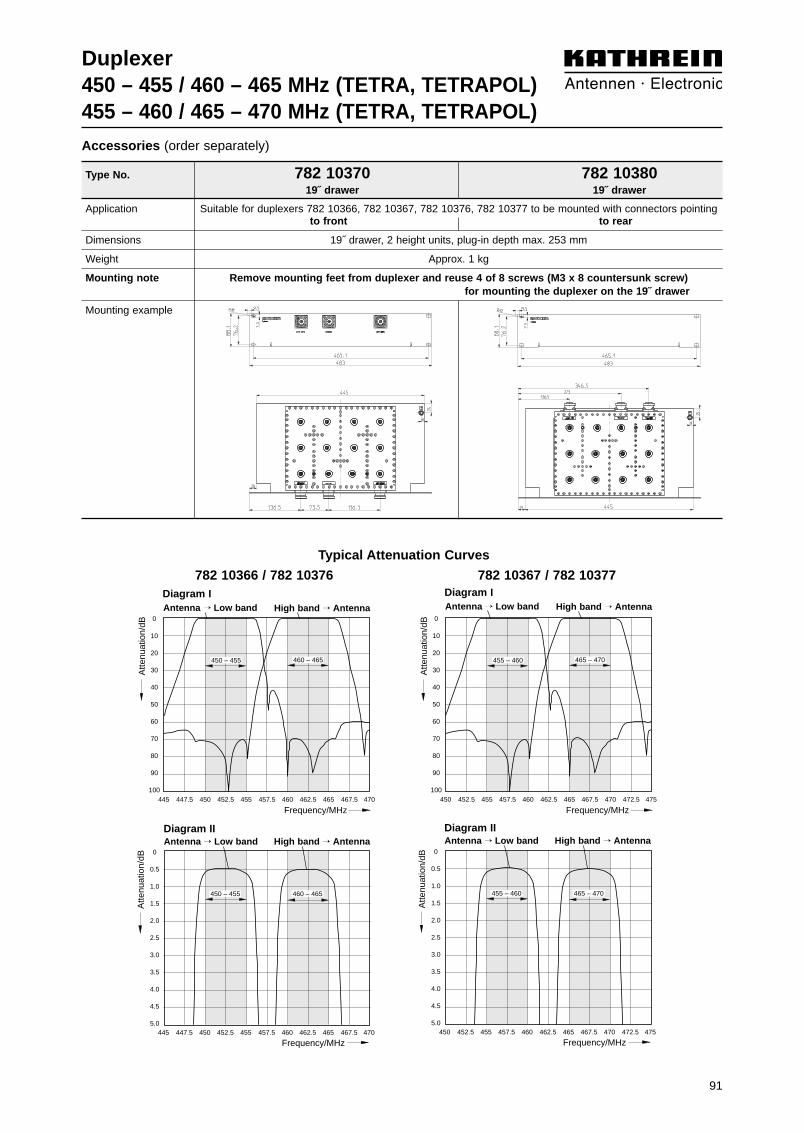
91
Duplexer450 – 455 / 460 – 465 MHz (TETRA, TETRAPOL)455 – 460 / 465 – 470 MHz (TETRA, TETRAPOL)
0
10
20
30
40
50
60
70
80
90
100
Atte
nuat
ion/
dB
Frequency/MHz445 447.5 450 452.5 455 457.5 460 462.5 465 467.5 470
450 – 455 460 – 465
Typical Attenuation Curves
Diagram IAntenna Low band High band Antenna
0
0.5
1.0
1.5
2.0
2.5
3.0
3.5
4.0
4.5
5.0
Atte
nuat
ion/
dB
Frequency/MHz445 447.5 450 452.5 455 457.5 460 462.5 465 467.5 470
460 – 465450 – 455
Diagram IIHigh band AntennaAntenna Low band
0
10
20
30
40
50
60
70
80
90
100
Atte
nuat
ion/
dB
Frequency/MHz450 452.5 455 457.5 460 462.5 465 467.5 470 472.5 475
455 – 460 465 – 470
Diagram IAntenna Low band High band Antenna
0
0.5
1.0
1.5
2.0
2.5
3.0
3.5
4.0
4.5
5.0
Atte
nuat
ion/
dB
Frequency/MHz450 452.5 455 457.5 460 462.5 465 467.5 470 472.5 475
465 – 470455 – 460
Diagram IIHigh band AntennaAntenna Low band
782 10366 / 782 10376 782 10367 / 782 10377
Accessories (order separately)
Application Suitable for duplexers 782 10366, 782 10367, 782 10376, 782 10377 to be mounted with connectors pointingto front to rear
Dimensions 19˝ drawer, 2 height units, plug-in depth max. 253 mm
Weight Approx. 1 kg
Mounting note Remove mounting feet from duplexer and reuse 4 of 8 screws (M3 x 8 countersunk screw)for mounting the duplexer on the 19˝ drawer
Mounting example
Type No. 782 10370 782 1038019˝ drawer 19˝ drawer

Number of resonators 4 6Frequency range 380 … 470 MHzInsertion loss 1.0 dB 1.5 dBVSWR < 1.4Impedance 50 ΩInput power < 200 WEffect of temperature < 1.5 kHz / °CTemperature range –30 … +60 °CMaterial Outer conductor: Aluminium
Inner conductor: Copper, silver-platedConnectors N femaleWeight 20.5 kg 30.5 kgPacking size 420 mm x 490 mm x 420 mm 420 mm x 490 mm x 630 mmDimensions (w x h x d) 190 mm x max. 350 mm x 760 mm 190 mm x max. 350 mm x 1140 mm
(with tuning rods) (with tuning rods)Attached hardware S-P filter with interconnecting cables,
2 brackets and 2 straps for each resonator
92
Duplexer380 … 470 MHz
The duplexer is suited to combine transmitters andreceivers (or transmitter and transmitter or receiverand receiver) to a common antenna.
It can be used :– for very small frequency spacing,– to obtain very high stop band attenuation (more
than 100 dB) at very low insertion loss.
Design and construction:The duplexer consists of four or six S-P filters K 65 21 26 1 and interconnecting cables of definedlength, depending on the operating frequencies.The S-P filters consist of temperature stabilized λ/4coaxial resonators. Using a specially temperaturestabilized coupling a high stop band attenuationcan be adjusted very close to the pass band fre-quency.
Tuning:The stop band attenuation is dependent on the frequency spacing and the number of S-P filters.The stop band attenuation for four or six S-P filterscan be read from the diagram.
The duplexer is tuned to the desired pass band frequencies at the factory. When ordering pleasespecify the pass band frequencies.
The duplexer can also be tuned on site using thesupplied instructions.
Installation:The duplexer can be used as a stand alone unit orwall mounted using the supplied brackets. The indi-vidual S-P filters can be connected to each otherusing the supplied straps.
Custom versions:For special applications more than six S-P filterscan be combined.
Type No. K 65 41 25 K 65 41 26
Technical Data
similar to K 65 41 25

93
Duplexer380 … 470 MHzTypical attenuation curves
Tuning examples:
120
110
100
90
80
70
60
0.5 1.0 1.5 2.0 2.5
2
1
Sto
p ba
ndat
tenu
atio
n/dB
Frequency spacing between pass band frequency andstop band frequency/MHz
4 1 1.0 dB K 65 41 256 2 1.5 dB K 65 41 26
Number of InsertionCurve Type No.resonators loss

94

95
Multiband Combiners andTransmitter Combiners
Filter Transmitter CombinersHybrid Transmitter Combiners
Multiband Combiners
Mu
ltib
and
Co
mb
iner
s an
dTr
ansm
itte
r C
om
bin
ers

96

Summary of Articles
Multiband Combiners and Transmitter Combiners:
97
Description Type No. Frequency range Max. input power Page... tunable bandwidth– fixed bandwidth (not tunable)
Filter Transmitter Combiner 792 100 146 ... 174 MHz 100 W 98
Filter Transmitter Combiner 792 101 146 ... 174 MHz 100 W 98
Filter Transmitter Combiner 792 102 146 ... 174 MHz 100 W 98
Filter Transmitter Combiner 793 205 146 ... 174 MHz 100 W 98
Filter Transmitter Combiner 793 206 146 ... 174 MHz 100 W 98
Filter Transmitter Combiner 790 044 420 ... 430 MHz 50 W 99
Filter Transmitter Combiner 790 594 460 ... 470 MHz 100 W 99
Hybrid Transmitter Combiner, 2 inputs 793 297 74 – 87 MHz 25 W 100
Hybrid Transmitter Combiner, 2 inputs 793 299 74 – 87 MHz 50 W 100
Hybrid Transmitter Combiner, 3 inputs 793 306 74 – 87 MHz 50 W 100
Hybrid Transmitter Combiner, 4 inputs 793 308 74 – 87 MHz 50 W 100
Hybrid Transmitter Combiner, 2 inputs 792 059 146 – 174 MHz 25 W 102
Hybrid Transmitter Combiner, 2 inputs 792 061 146 – 174 MHz 100 W 102
Hybrid Transmitter Combiner, 3 inputs 792 064 146 – 174 MHz 100 W 102
Hybrid Transmitter Combiner, 4 inputs 792 067 146 – 174 MHz 100 W 102
Hybrid Transmitter Combiner, 2 inputs 784 10168 380 – 430 MHz 25 W 104
Hybrid Transmitter Combiner, 2 inputs 784 10167 380 – 430 MHz 100 W 104
Hybrid Transmitter Combiner, 3 inputs 784 10166 380 – 430 MHz 100 W 104
Hybrid Transmitter Combiner, 4 inputs 784 10140 380 – 430 MHz 100 W 104
Hybrid Transmitter Combiner, 5 inputs 784 10165 380 – 430 MHz 100 W 104
Hybrid Transmitter Combiner, 2 inputs 791 644 400 – 470 MHz 25 W 106
Hybrid Transmitter Combiner, 2 inputs 791 646 400 – 470 MHz 100 W 106
Hybrid Transmitter Combiner, 3 inputs 791 649 400 – 470 MHz 100 W 106
Hybrid Transmitter Combiner, 4 inputs 791 652 400 – 470 MHz 100 W 106
Hybrid Transmitter Combiner, 5 inputs 784 10063 400 – 470 MHz 100 W 106
Multiband Combiner K 64 50 4 68 – 87.5 / 146 – 174 MHz 50 W 108
Multiband Combiner 719 035 68 – 87.5 / 146 – 174 MHz 50 W 108
Multiband Combiner 719 792 68 – 108 / 146 – 174 MHz 50 W 108
Multiband Combiner 718 500 68 – 87.5 / 146 – 174 / 400 – 470 MHz 25 W 108
Multiband Combiner 721 138 68 – 174 / 380 – 470 MHz 50 W 110
Multiband Combiner 723 013 68 – 174 / 380 – 470 MHz 50 W 110
Multiband Combiner 790 244 68 – 174 / 400 – 470 MHz 50 W 110
Multiband Combiner 790 957 68 – 174 / 400 – 470 MHz 50 W 110
Multiband Combiner 728 954 68 – 470 / 870 – 970 MHz 50 W 111
Multiband Combiner 791 463 68 – 470 / 870 – 970 MHz 50 W 111
Multiband Combiner 722 437 68 – 470 MHz / 870 – 970 MHz 500 W 111
Multiband Combiner 722 440 68 – 470 MHz / 870 – 970 MHz 500 W 111
Dual-Band Combiner 782 10369 380 – 400 / 410 – 430 MHz 200 W 112
Dual-Band Combiner 782 10460 50 – 470 / 806 – 2500 MHz 500 W 113
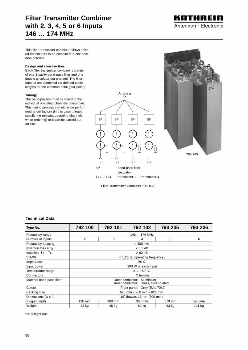
98
Type No. 792 100 792 101 792 102 793 205 793 206
Filter Transmitter Combiner with 2, 3, 4, 5 or 6 Inputs146 … 174 MHz
Frequency range 146 ... 174 MHzNumber of inputs 2 3 4 5 6Frequency spacing > 300 kHzInsertion loss at f0 < 3.5 dBIsolation Tx – Tx > 60 dBVSWR < 1.25 (at operating frequency)Impedance 50 ΩInput power 100 W of each inputTemperature range 0 … +50 °CConnectors N female Material band-pass filter Outer conductor: Aluminium
Inner conductor: Brass, silver-platedColour Front panel: Grey (RAL 7032)Packing size 620 mm x 950 mm x 820 mmDimensions (w x h) 19˝ drawer, 18 hu* (800 mm) Plug-in depth 190 mm 380 mm 380 mm 570 mm 570 mmWeight 33 kg 46 kg 62 kg 83 kg 101 kg
*hu = hight unit
Technical Data
This filter transmitter combiner allows seve-ral transmitters to be combined to one com-mon antenna.
Design and construction:Each filter transmitter combiner consists of one 1-cavity band-pass filter and onedouble circulator per channel. The filter outputs are combined via defined cablelengths to one common point (star-point).
Tuning:The band-passes must be tuned to the individual operating channels concerned.This tuning process can either be perfor-med at our factory (in this case, pleasespecify the relevant operating channelswhen ordering) or it can be carried out on site.
BP band-pass filter↑ circulatorTx1 ... Tx4 transmitter 1 ... transmitter 4
Filter Transmitter Combiner 792 102
793 205
Antenna

Frequency range 420 … 430 MHz 460 ... 470 MHz
Number of channels 4
Isolators per channel 2
Channel spacing > 150 kHz
Insertion loss Tx → AntennaChannel spacing 150 / 200 / 250 kHzWith 50 W input power < 4.3 / < 3.9 / < 3.6 dBWith 100 W input power < 4.5 / < 4.1 / < 3.8 dB
Isolation Tx ↔ Tx > 60 dB
VSWR at Tx inputs < 1.3
Impedance 50 Ω
Input power per channel < 100 W
Power rating of the loads < 60 W
Temperature range 0 … +50 °C
ConnectorsTx inputs N femaleAntenna 7-16 female N femaleDetector outputs (DC) SMC male
Material Band-pass filters: Copper / brass19˝ drawer: Aluminium
Colour Grey (RAL 7032)
Weight Approx. 22.5 kg
Packing size 565 mm x 435 mm x 380 mm
Dimensions (w x h x d) 19˝ drawer, 8 height units, plug-in depth: 370 mm
Technical Data
The 4-channel Transmitter Combiner is suitable forcombining up to 4 transmitters to a single antennaoutput.
• 4 x 1-cavity high Q band-pass filters, combined in one compact unit
• 4 x double isolators, each with one internal low power 50-Ω load
• 4 x high power 50-Ω loads with integrated detectors for reflected Tx signals
• Tuning can be achieved with a Network Analyzer or with aVoltmeter by using the DC voltage signals supplied at thedetector outputs
• Self-locking tuning screws
• Expansion of up to 16 channels is possible by interconnec-ting several 4-channel combiners with suitable starpoint cables
Expansion to ... 8-channel transmitter combiner 12-channel transmitter combiner 16-channel transmitter combiner
Insertion lossChannel spacing 150 / 200 / 250 kHz 150 / 200 / 250 kHz 150 / 200 / 250 kHzWith 50 W input power < 4.7 / < 4.3 / < 4.0 dB < 5.5 / < 5.1 / < 4.8 dB < 5.7 / < 5.3 / < 5.0 dBWith 100 W input power < 4.9 / < 4.5 / < 4.2 dB < 5.7 / < 5.3 / < 5.0 dB < 5.9 / < 5.5 / < 5.2 dB
BP Band-pass filter↑ CirculatorTx1 ... Tx4 Transmitter inputs 1 ... 4 DC Detector outputs (DC voltage)
Type No. 790 044 790 594
Tx1
Tx2
Tx3
Tx4
Antenna
790 044
99
Filter Transmitter Combiner 420 … 430 MHz460 ... 470 MHz

100
Hybrid Transmitter Combiner74 – 87 MHz
The hybrid transmitter combiner allows twoor several transmitters to be combined to acommon output.
Special features:– very small spacing of the transmitting
frequencies, down to adjacent channel spacing,
– variable transmitter frequencies,– small dimensions.
Design and construction:The hybrid transmitter combiner has two,three or four inputs and one output. For combining transmitters a hybrid ringjunction or a decoupled power splitter isused as hybrid, depending on the numberof inputs. In every transmitting path a wideband dual circulator is inserted, which causes very high isolation. This effectivelysuppresses intermodulation products. Theabsorbers are dimensioned for a possibletotal reflection occurring at the output.
Custom versions:Custom versions are available on request:– with single circulator instead of dual
circulator, if lower isolation is sufficient,– with a band-pass filter at the output,– for higher power.
Type No. Inputs Insertion loss Dimensions Input power Packing size19˝ drawer of each input
height plug-in depth
793 297 2 < 4.9 dB 1 hu* = 45 mm 350 mm 25 W 535 mm x 120 mm x 435 mm793 299 2 < 4.9 dB 4 hu* = 177 mm 350 mm 50 W 535 mm x 260 mm x 490 mm793 306 3 < 7.2 dB 4 hu* = 177 mm 350 mm 50 W 535 mm x 260 mm x 490 mm793 308 4 < 8.4 dB 4 hu* = 177 mm 350 mm 50 W 535 mm x 260 mm x 490 mmFrequency range 74 – 87 MHzMin. frequency spacing 0 MHzIsolation > 60 dBImpedance 50 ΩVSWR < 1.25Connectors N femaleColour Front panel: Grey (RAL 7032)
* hu = height unit
Technical Data
793 297
793 308

101
Hybrid Transmitter Combinerwith 2, 3 or 4 Inputs74 – 87 MHz
Hybrid
Output
Input 2Input 1
Output
Input 1 Input 2 Input 3
junction
Decoupledpower splitter
1 : 3
ring
Input 1 Input 2
Decoupled
Input 4Input 3
power splitter1 : 4
Output
793 297, 793 299
793 306
793 308

102
Hybrid Transmitter Combinerwith 2, 3 or 4 Inputs146 – 174 MHz
The hybrid transmitter combiner allows twoor several transmitters to be combined to acommon output.
Special features:– very small spacing of the transmitting fre-
quencies, down to adjacent channel spa-cing,
– variable transmitter frequencies,– small dimensions.
Design and construction:The hybrid transmitter combiner has two,three or four inputs and one output. Forcombining transmitters a hybrid ring junc-tion or a decoupled power splitter is usedas hybrid, depending on the number of in-puts. In every transmitting path a wide banddual circulator is inserted, which causesvery high isolation. This effectively suppres-ses intermodulation products. The absor-bers are dimensioned for a possible totalreflection occurring at the output.
792 059
792 067
Type No. Inputs Insertion loss Dimensions Input power Packing size19” drawer of each input
height plug-in depth
792 059 2 < 4.1 dB 1 hu* = 45 mm 350 mm 25 W 535 mm x 120 mm x 435 mm792 061 2 < 4.1 dB 4 hu* = 177 mm 350 mm 100 W 535 mm x 260 mm x 490 mm792 064 3 < 6.3 dB 4 hu* = 177 mm 350 mm 100 W 540 mm x 192 mm x 520 mm792 067 4 < 7.5 dB 4 hu* = 177 mm 350 mm 100 W 540 mm x 192 mm x 520 mmFrequency range 146 – 174 MHzMin. frequency spacing 0 MHzIsolation > 65 dBImpedance 50 ΩVSWR < 1.25Connectors N femaleColour Front panel: Grey (RAL 7032)
* hu = height unit
Technical Data

103
Hybrid Transmitter Combinerwith 2, 3 or 4 Inputs146 – 174 MHz
Hybrid
Output
Input 2Input 1
Output
Input 1 Input 2 Input 3
junction
Decoupledpower splitter
1 : 3
ring
Input 1 Input 2
Decoupled
Input 4Input 3
power splitter1 : 4
Output
792 059, 792 061
792 064
792 067

104
Type No. Inputs Insertion loss Dimensions Input power Packing size19˝ drawer per input
height plug-in depth
Hybrid Transmitter Combiner380 – 430 MHz(TETRA, TETRAPOL)
784 10168 2 < 3.9 dB 1 hu* = 44 mm 300 mm 25 W 535 mm x 120 mm x 435 mm784 10167 2 < 3.9 dB 4 hu* = 177 mm 350 mm 100 W 535 mm x 260 mm x 490 mm784 10166 3 < 6.3 dB 4 hu* = 177 mm 350 mm 100 W 535 mm x 260 mm x 490 mm784 10140 4 < 7.3 dB 4 hu* = 177 mm 350 mm 100 W 535 mm x 260 mm x 490 mm784 10165 5 < 8.3 dB 4 hu* = 177 mm 350 mm 100 W 535 mm x 260 mm x 490 mmFrequency range 380 – 430 MHzMin. frequency spacing 0 MHzIsolation > 70 dBImpedance 50 ΩVSWR < 1.2Connectors N femaleColour Front panel: Grey (RAL 7032)
* hu = height unit
Technical Data
The hybrid transmitter combiner allows twoor more transmitters to be combined to acommon output.
Special features:– very small spacing of the transmitting
frequencies, down to adjacent channel spacing,
– variable transmitter frequencies,– small dimensions.
Design:The hybrid transmitter combiner has two,three, four or five inputs and one output.For combining transmitters a hybrid ringjunction a decoupled power splitter is usedas hybrid or couplers depending on thenumber of inputs. In every transmitting patha wide band dual circulator is inserted,which causes very high isolation. Thiseffectively suppresses intermodulation products. The absorbers are dimensionedfor a possibly occurring total reflection atthe output.
784 10168
784 10140

105
Input 1 Input 2
Decoupled
Input 4Input 3
power splitter1 : 4
Output
Output
Input 1 Input 2 Input 3
Decoupledpower splitter
1 : 3
Hybrid
Output
Input 2Input 1
junctionring
Hybrid Transmitter Combiner380 – 430 MHz(TETRA, TETRAPOL)
784 10168784 10167
784 10166
784 10140 784 10165
Output

106
Type No. Inputs Insertion loss Dimensions Input power Packing size19˝ drawer per input
height plug-in depth
Hybrid Transmitter Combiner400 – 470 MHz
791 644 2 < 3.9 dB 1 hu* = 44 mm 300 mm 25 W 535 mm x 120 mm x 435 mm791 646 2 < 3.9 dB 4 hu* = 177 mm 350 mm 100 W 535 mm x 260 mm x 490 mm791 649 3 < 6.3 dB 4 hu* = 177 mm 350 mm 100 W 535 mm x 260 mm x 490 mm791 652 4 < 7.3 dB 4 hu* = 177 mm 350 mm 100 W 535 mm x 260 mm x 490 mm784 10063 5 < 8.3 dB 4 hu* = 177 mm 350 mm 100 W 535 mm x 260 mm x 490 mmFrequency range 400 – 470 MHzMin. frequency spacing 0 MHzIsolation > 70 dBImpedance 50 ΩVSWR < 1.2Connectors N femaleColour Front panel: Grey (RAL 7032)
* hu = height unit
Technical Data
The hybrid transmitter combiner allows twoor more transmitters to be combined to acommon output.
Special features:– very small spacing of the transmitting
frequencies, down to adjacent channel spacing,
– variable transmitter frequencies,– small dimensions.
Design:The hybrid transmitter combiner has two,three, four or five inputs and one output.For combining transmitters a hybrid ringjunction a decoupled power splitter is usedas hybrid or couplers depending on thenumber of inputs. In every transmitting patha wide band dual circulator is inserted,which causes very high isolation. Thiseffectively suppresses intermodulation products. The absorbers are dimensionedfor a possibly occurring total reflection atthe output.
791 644
791 652

107
Input 1 Input 2
Decoupled
Input 4Input 3
power splitter1 : 4
Output
Output
Input 1 Input 2 Input 3
Decoupledpower splitter
1 : 3
Hybrid
Output
Input 2Input 1
junctionring
Hybrid Transmitter Combiner400 – 470 MHz
791 644791 646
791 649
791 652 784 10063
Output
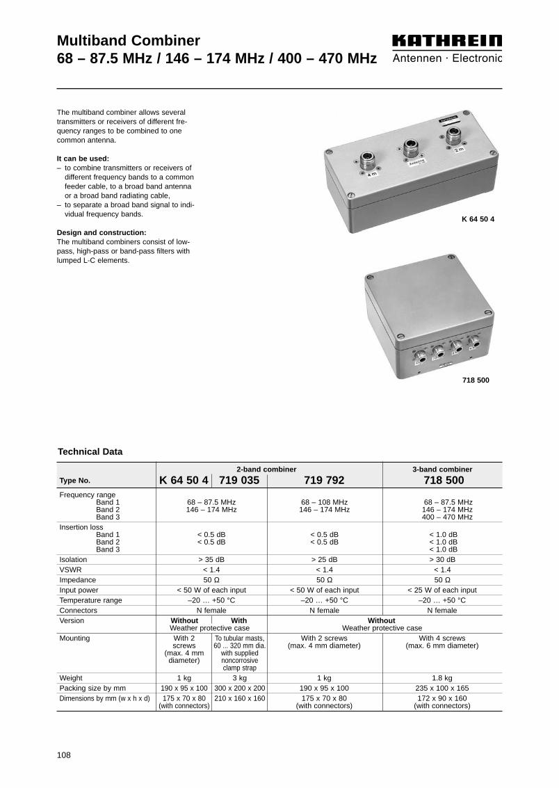
108
Multiband Combiner68 – 87.5 MHz / 146 – 174 MHz / 400 – 470 MHz
The multiband combiner allows severaltransmitters or receivers of different fre-quency ranges to be combined to one common antenna.
It can be used:– to combine transmitters or receivers of
different frequency bands to a commonfeeder cable, to a broad band antenna or a broad band radiating cable,
– to separate a broad band signal to indi-vidual frequency bands.
Design and construction:The multiband combiners consist of low-pass, high-pass or band-pass filters withlumped L-C elements.
K 64 50 4
718 500
2-band combiner 3-band combiner
Type No. K 64 50 4 719 035 719 792 718 500Frequency range
Band 1 68 – 87.5 MHz 68 – 108 MHz 68 – 87.5 MHzBand 2 146 – 174 MHz 146 – 174 MHz 146 – 174 MHzBand 3 400 – 470 MHz
Insertion lossBand 1 < 0.5 dB < 0.5 dB < 1.0 dBBand 2 < 0.5 dB < 0.5 dB < 1.0 dBBand 3 < 1.0 dB
Isolation > 35 dB > 25 dB > 30 dBVSWR < 1.4 < 1.4 < 1.4Impedance 50 Ω 50 Ω 50 ΩInput power < 50 W of each input < 50 W of each input < 25 W of each inputTemperature range –20 … +50 °C –20 … +50 °C –20 … +50 °CConnectors N female N female N femaleVersion Without With Without
Weather protective case Weather protective caseMounting With 2 To tubular masts, With 2 screws With 4 screws
screws 60 ... 320 mm dia. (max. 4 mm diameter) (max. 6 mm diameter)(max. 4 mm with supplied diameter) noncorrosive
clamp strap Weight 1 kg 3 kg 1 kg 1.8 kgPacking size by mm 190 x 95 x 100 300 x 200 x 200 190 x 95 x 100 235 x 100 x 165Dimensions by mm (w x h x d) 175 x 70 x 80 210 x 160 x 160 175 x 70 x 80 172 x 90 x 160
(with connectors) (with connectors) (with connectors)
Technical Data

109
Multiband Combiner68 – 87.5 MHz / 146 – 174 MHz / 380 – 470 MHz
Antenna
Feeder Cable
Multiband Combiner722 437
MultibandCombiner
K 64 50 4
68 – 87.5 MHz 146 – 176 MHz
400 – 470 MHz
870 – 970 MHzMultibandCombiner721 138
Example for multiband combiners in cascade
CombinerMultiband CombinerK 64 50 4
Multiband Combiner719 035(with weather protective case)
Fee
der
cabl
e
Antenna146 – 174 MHz
Antenna68 – 87.5 MHz
Combiner
146 – 174 MHz68 – 87.5 MHz
Example for the combining of 80 MHz and 160 MHz tansmitters/receivers to a common feeder cable
380 – 470 MHz

110
Frequency rangeBand 1 68 – 174 MHz 68 – 174 MHzBand 2 380 – 470 MHz 400 – 470 MHz
Insertion lossBand 1 < 0.5 dB < 0.5 dBBand 2 < 0.5 dB < 0.5 dB
Isolation > 35 dB > 45 dB
VSWR < 1.4 < 1.25
Impedance 50 Ω 50 Ω
Input power < 50 W of each input < 50 W of each input
Temperature range –20 … +50 °C –20 … +50 °C
Connectors N female, silver-plated N female
Version Without With Without WithWeather protective case Weather protective case
Mounting With 2 screws To tubular masts, With 2 screws To tubular masts,(max. 4 mm diameter) 60 ... 320 mm diameter (max. 4 mm diameter) 60 ... 320 mm diameter
with supplied non- with supplied non-corrosive clamp strap corrosive clamp strap
Weight 1 kg 3 kg 0.3 kg 0.7 kgPacking size 190 mm x 95 mm x 100 mm 300 mm x 200 mm x 200 mm 130 mm x 50 mm x 130 mm 240 mm x 160 mm x 130 mmDimensions (w x h x d) 175 mm x 70 mm x 80 mm 210 mm x 160 mm x 160 mm 103 mm x 38 mm x 68 mm 210 mm x 100 mm x 130 mm
(including connectors) (including connectors)
Multiband Combiner68 – 174 / 380 – 470 MHz
It can be used:– to combine several transmitters and
receivers in two or three different fre-quency bands to a common feedercable, to a broad-band antenna, or to a broad-band radiating cable,
– and, in the reverse operating mode, toseparate several transmission or recei-ving frequencies into two or three fre-quency bands.
Design and construction:The multiband combiners consist of lowpass, high pass or band-pass filters withlumped L-C elements.The 2-range combiners can be deliveredwith or without weather protective cases.
2-range combiner
Type No. 721 138 723 013 790 244 790 957
Technical Data
790 244
721 138

Multiband Combiner68 – 470 / 870 – 970 MHz
Type No. 728 954 791 463 722 437 722 440Frequency range
Input 1 68 – 470 MHz 68 – 470 MHzInput 2 870 – 970 MHz 870 – 970 MHz
Insertion loss68 – 470 MHz < 0.5 dB < 0.5 dB
870 – 970 MHz < 0.5 dB < 0.5 dBIsolation > 45 dB > 38 dBVSWR < 1.2 < 1.5Impedance 50 Ω 50 ΩInput power
68 – 470 MHz < 50 W < 500 W870 – 970 MHz < 50 W < 300 W
Temperature range –20 … +70 °C –20 … +50 °CConnectors N female 7-16 female
Technical Data
The multiband combiners can be used:– to combine several transmitters and receivers
in two different frequency bands to a commonfeeder cable, to a broad-band antenna, or to abroad-band radiating cable,
– and, in the reverse operating mode, to separateseveral transmission or receiving frequenciesinto two frequency bands.
Design and construction:The multiband combiners 722 437 and 722 440consists of a coaxial low-pass filter and a 3-cavityband-pass filter with λ/4 resonators.The multiband combiners 728 954 and 791 463consist of a low-pass and high-pass filter in printedcircuit technology.
Version Without With Without WithWeather protective case Weather protective case
Mounting With 4 screws To tubular masts, With 4 screws With 4 screws(max. 3 mm diameter) 60 ... 320 mm diameter (max. 4 mm diameter) (max. 12 mm diameter)
with supplied non-corrosive clamp strap
Weight 1.3 kg 3 kg 3 kg 20 kgPacking size Approx. Approx. Approx. Approx.
280 mm x 55 mm x 125 mm 540 mm x 120 mm x 260 mm 145 mm x 145 mm x 625 mm 970 mm x 240 mm x 410 mmDimensions (w x h x d) 269 mm x 32 mm x 112 mm 400 mm x 60 mm x 172 mm 120 mm x 76 mm x 520 mm 793 mm x 218 mm x 380 mm
(including connectors) (including connectors) (including connectors) (including connectors)
728 954
722 437
111

Dual-Band Combiner380 – 400 MHzTETRA / TETRAPOL
410 – 430 MHzTETRA / TETRAPOL
• Designed for co-siting purposes
• Enables feeder sharing
• Suitable for indoor applications
• Built-in DC stop
• 19 ˝ drawer available on request
Type No. 782 10369Pass band
Band 1 380 – 400 MHzBand 2 410 – 430 MHz
Insertion lossPort 1 ↔ Port 3 < 0.8 dB (380 – 400 MHz)Port 2 ↔ Port 3 < 0.8 dB (410 – 430 MHz)
IsolationPort 1 ↔ Port 2 > 60 dB (380 – 400 MHz)
> 60 dB (410 – 430 MHz)
VSWR < 1.2 (380 – 400 / 410 – 430 MHz)
Impedance 50 ΩInput power
Band 1 < 200 WBand 2 < 200 W
Intermodulation products < –150 dBc (3rd order; with 2 x 20 W)
Temperature range –20 ... +60 °C
Connectors 7-16 female
Application Indoor
Special features Built-in DC stop between all ports
Mounting With 4 screws (max. 4 mm diameter)
Weight Approx. 6.2 kg
Packing size Approx. 320 mm x 260 mm x 200 mm
Dimensions (w x h x d) 315 mm x 87.5 mm x 244.6 mm(including connectors and mounting feet)
Technical Data
0
0.5
1.0
1.5
2.0
2.5
3.0
3.5
4.0
4.5
5.0
Atte
nuat
ion/
dB
Frequency/MHz355 365 375 385 395 405 415 425 435 445 455
380 – 400 410 – 430
0
10
20
30
40
50
60
70
80
90
100
Atte
nuat
ion/
dB
Frequency/MHz355 365 375 385 395 405 415 425 435 445 455
380 – 400 410 – 430
Calculated Attenuation Curves
Port 1 ↔ Port 3 Port 2 ↔ Port 3Diagram I
Diagram IIPort 1 ↔ Port 3 Port 2 ↔ Port 3
Low band Antenna High band
112
0
10
20
30
40
50
60
70
80
90
100
Atte
nuat
ion/
dB
Frequency/MHz0 250 500 750 1000 1250 1500 1750 2000 2250 2500
50 – 470 1710 – 2500806 – 960
Typical Attenuation Curves
Diagram II
Diagram IPort 1 ↔ Port 3 Port 2 ↔ Port 3
Port 1 ↔ Port 3 Port 2 ↔ Port 3
0
0.1
0.2
0.3
0.4
0.5
0.6
0.7
0.8
0.9
1.00 250 500 750 1000 1250 1500 1750 2000 2250 2500
Atte
nuat
ion/
dB
Frequency/MHz
1710 – 2500806 – 960 50 – 470
Dual-Band Combiner50 – 470 MHz
PMR / TETRA / TETRAPOL806 – 2500 MHz
CDMA 800 / GSM 900 / GSM 1800 / UMTS / WLAN
• Designed for co-siting purposes
• Enables feeder sharing
• Can be used as a combiner near the BTS or in a reciprocal function near the antenna
• Suitable for indoor or outdoor applications
• Wall or mast mounting
• Built-in lightning protection
• External DC stop available as an accessory
• Very low insertion loss
• High input power
Type No. 782 10460Pass band
Band 1 50 – 470 MHzBand 2 806 – 960 / 1710 – 2500 MHz
Insertion lossPort 1 ↔ Port 3 < 0.2 dB (50 – 470 MHz)Port 2 ↔ Port 3 < 0.2 dB (806 – 960 / 1710 – 2500 MHz)
IsolationPort 1 ↔ Port 2 > 50 dB (50 – 470 / 806 – 2500 MHz)
VSWR < 1.25 (50 – 470 / 806 – 960 / 1710 – 2500 MHz)
Impedance 50 Ω
Input powerBand 1 < 500 WBand 1 < 500 W
Intermodulation products < –160 dBc (2nd/3rd order; with 2 x 20 W)
Temperature range –55 ... +60 °C
Connectors 7-16 female
Application Indoor or outdoor (IP 66)
DC/AISG transparencyPort 1 ↔ Port 3 By-pass (max. 2500 mA)Port 2 ↔ Port 3 Stop
Lightning protection 3 kA, 10/350 µs pulse
Mounting Wall mounting: With 4 screws (max. 8 mm diameter)Mast mounting: With additional clamp set
Weight Approx. 2.9 kg
Dimensions (w x h x d) Approx. 125 x 350 x 64 mm(including mounting brackets)
Technical Data
Port 1
Port 2
Port 3
113

114

3-dB CouplersSystem Components 4.7-dB, 6-dB, 7-dB, 10-dB CouplersHybrid Ring Junctions
Decoupled Power SplittersCirculators
DC-StopsAttenuators50-Ω Loads S
yste
m C
om
po
nen
ts
115

3-dB Coupler K 62 70 41 68 – 108 MHz 1000 W 118
3-dB Coupler K 62 70 47 68 – 108 MHz 1000 W 118
4.7-dB Coupler 720 938 68 – 108 MHz 1000 W 119
4.7-dB Coupler 793 097 68 – 108 MHz 1000 W 119
6-dB Coupler 793 098 68 – 108 MHz 1000 W 119
6-dB Coupler 793 099 68 – 108 MHz 1000 W 119
7-dB Coupler 793 100 68 – 108 MHz 1000 W 119
7-dB Coupler 793 101 68 – 108 MHz 1000 W 119
10-dB Coupler 720 296 68 – 108 MHz 1000 W 119
10-dB Coupler 721 000 68 – 108 MHz 1000 W 119
Hybrid Ring Junction K 62 73 41 68 – 87.5 MHz 100 W 120
Decoupled Power Splitter 1:3 724 346 68 – 87.5 MHz 100 W 121
Decoupled Power Splitter 1:4 725 870 68 – 87.5 MHz 100 W 121
Circulator 793 276 68 – 88 MHz 50 W 122
DC-Stop 721 062 68 – 87.5 / 146 – 174 / 380 – 470 MHz 10 W 123
3-dB Coupler K 62 70 21 140 – 180 MHz 800 W 124
3-dB Coupler K 62 70 27 140 – 180 MHz 800 W 124
4.7-dB Coupler 717 401 146 – 174 MHz 800 W 125
4.7-dB Coupler 793 102 146 – 174 MHz 800 W 125
6-dB Coupler 721 060 146 – 174 MHz 800 W 125
6-dB Coupler 793 103 146 – 174 MHz 800 W 125
7-dB Coupler 719 090 146 – 174 MHz 800 W 125
7-dB Coupler 793 104 146 – 174 MHz 800 W 125
10-dB Coupler 720 298 146 – 174 MHz 800 W 125
10-dB Coupler 722 675 146 – 174 MHz 800 W 125
Hybrid Ring Junction K 62 73 21 146 – 174 MHz 100 W 126
Decoupled Power Splitter 1:3 724 347 146 – 174 MHz 100 W 127
Decoupled Power Splitter 1:4 725 234 146 – 174 MHz 100 W 127
Circulator 793 277 146 – 174 MHz 100 W 128
Circulator 780 060 146 – 174 MHz 100 W 129
3-dB Coupler K 63 70 21 340 – 512 MHz 500 W 130
3-dB Coupler K 63 70 27 340 – 512 MHz 500 W 130
4.7-dB Coupler 719 782 380 – 470 MHz 500 W 131
4.7-dB Coupler 722 488 380 – 470 MHz 500 W 131
6-dB Coupler 792 777 380 – 470 MHz 500 W 131
6-dB Coupler 790 589 380 – 470 MHz 500 W 131
7-dB Coupler 792 331 380 – 470 MHz 500 W 131
7-dB Coupler 790 590 380 – 470 MHz 500 W 131
10-dB Coupler 720 297 380 – 470 MHz 500 W 131
10-dB Coupler 720 942 380 – 470 MHz 500 W 131
Hybrid Ring Junction, TETRA, TETRAPOL 730 092 380 – 430 MHz 100 W 132
Hybrid Ring Junction K 63 73 21 1 400 – 470 MHz 100 W 133
Decoupled Power Splitter 1 : 3 782 10231 380 – 430 MHz 100 W 134
Decoupled Power Splitter 1 : 4 782 10189 380 – 430 MHz 100 W 134
Decoupled Power Splitter 1 : 3 724 348 400 – 470 MHz 100 W 135
Decoupled Power Splitter 1 : 4 725 871 400 – 470 MHz 100 W 135
Circulator 784 10175 380 – 430 MHz 200 W 136
Circulator 790 215 400 – 470 MHz 100 W 136
Circulator 791 630 400 – 470 MHz 100 W 137
Description Type No. Frequency range Max. input power Page... tunable bandwidth– fixed bandwidth (not tunable)
116
Summary of Articles
System Components:

Summary of Articles
System Components:
Description Type No. Frequency range Attenuation Max. input power Page... tunable bandwidth– fixed bandwidth (not tunable)
117
Attenuator 784 10235 0 – 4000 MHz 3 dB 2 W 138
Attenuator 784 10236 0 – 4000 MHz 6 dB 2 W 138
Attenuator 784 10237 0 – 4000 MHz 10 dB 2 W 138
Attenuator 784 10238 0 – 4000 MHz 20 dB 2 W 138
Attenuator 791 918 0 – 4000 MHz 3 dB 15 W 139
Attenuator 791 919 0 – 4000 MHz 6 dB 12 W 139
Attenuator 791 920 0 – 4000 MHz 10 dB 10 W 139
Attenuator 791 921 0 – 4000 MHz 20 dB 10 W 139
50-Ω Load K 62 26 61 1 0 – 2500 MHz – 0.5 W 140
50-Ω Load 784 10367 0 – 4000 MHz – 1.5 W 140
50-Ω Load K 62 26 11 1 0 – 2500 MHz – 2 W 140
50-Ω Load K 62 26 40 1 0 – 2500 MHz – 10 W 141
50-Ω Load K 62 26 41 1 0 – 2500 MHz – 10 W 141
50-Ω Load K 62 26 20 1 0 – 2500 MHz – 25 W 141
50-Ω Load K 62 26 21 1 0 – 2500 MHz – 25 W 141
50-Ω Load K 62 26 20 7 0 – 2500 MHz – 25 W 141
50-Ω Load K 62 26 21 7 0 – 2500 MHz – 25 W 141
50-Ω Load K 62 26 30 1 0 – 2500 MHz – 50 W 141
50-Ω Load K 62 26 31 1 0 – 2500 MHz – 50 W 141
50-Ω Load K 62 26 30 7 0 – 2500 MHz – 50 W 141
50-Ω Load K 62 26 31 7 0 – 2500 MHz – 50 W 141
50-Ω Load K 62 26 50 1 0 – 1000 MHz – 100 W 141
50-Ω Load K 62 26 51 1 0 – 1000 MHz – 100 W 141
50-Ω Load K 62 26 50 7 0 – 1000 MHz – 100 W 141

118
3-dB Coupler (90° Hybrid)68 – 108 MHz
K 62 70 47
1.0 1.5 2.0
15
20
25
Atte
nuat
ion
2 ↔
3 /
dB
VSWR at port 1(with 50-Ω load at port 4)
Attenuation 2 ↔ 3 vs VSWR at port 1
Type No. K 62 70 41 K 62 70 47Connectors N female 7-16 female
silver-plated silver-plated
Frequency range 68 – 108 MHz
Attenuation 1 ↔ 2 / 1 ↔ 3 3 ±0.4 dBAttenuation 2 ↔ 3 See diagram
Directivity > 35 dB
VSWR < 1.06
Impedance 50 ΩMax. power 1000 W
Colour Grey (RAL 7032)
Installation With 2 screws (max. 6 mm diameter)
Weight 2.3 kg
Packing size 931 mm x 126 mm x 54 mm
Dimensions (w x h x d) 886 mm x 40 mm x 95 mm 885 mm x 40 mm x 84 mm(incl. connectors) (incl. connectors)
Note: VSWR and attenuation are measured when the remaining ports are terminated with 50-Ω loads.
Technical Data
The 3-dB coupler can be used:– as decoupled power splitter with a ratio
of 1:1,– for the decoupled combining of two trans-
mitters with arbitrarily low frequency spa-cing (at 3-dB loss),
– for the decoupled combining of two recei-vers with arbitrarily low frequency spacing,
– for the decoupled combining of two trans-mitter/receiver units, whose integratedduplexers are within the same frequencyrange,
– as a frequency independent 90° phaseshifter,
– as a component to form combiners.
Design and function:The 3-dB coupler has four ports, two ofwhich are decoupled from each other. For example effective power entering intoport 1 is distributed into ports 2 and 3. Port 4 is decoupled and without power ifports 2 and 3 are ideally matched. In practi-ce an absorber of suitable power is to beplanned for according to the mismatch ofports 2 and 3.
Decoupled combining can be achieved viathe diagonally opposite ports 2 and 3respectively 1 and 4.
Any open ports must be terminated with suitable loads.
1↔ 3
1↔ 22.5
3.0
3.5
108
Typical attenuation 1↔ 2 and 1↔ 3vs frequency
Atte
nuat
ion
1↔
3 /
dB
Atte
nuat
ion
1↔
2 /
dB
1 3
2 4
68Frequency/MHz

119
4.7-dB, 6-dB, 7-dB, 10-dB Coupler (90° Hybrid)68 – 108 MHz
Type No. N female 720 938 793 098 793 100 720 2967-16 female 793 097 793 099 793 101 721 000
Version 4.7-dB coupler 6-dB coupler 7-dB coupler 10-dB couplerFrequency range 68 – 108 MHzAttenuation 1↔3 (4↔2) 1.8 ±0.3 dB 1.25 ±0.2 dB 1.0 ±0.2 dB 0.5 ±0.2 dBAttenuation 1↔2 (4↔3) 4.7 ±0.5 dB 6.0 ±0.5 dB 7.0 ±0.5 dB 10 ±0.5 dBDirectivity > 30 dBVSWR < 1.1Impedance 50 ΩInput power < 1000 W total power Connectors Silver-platedMaterial Brass, silver-platedColour Grey (RAL 7032)Installation With 2 screws (max. 5 mm diameter)Weight 2.2 kg 2.8 kg 2.8 kg 3.5 kgPacking size 910 mm x 47 mm x 115 mm Dimensions
N female (w x h x d) 886 mm x 40 mm x 95 mm (with connectors)7-16 female (w x h x d) 886 mm x 40 mm x 84 mm (with connectors)
Note: VSWR and attenuation are measured when the remaining ports are terminated with 50-Ω loads.
Technical Data
1 3
2 4
The 4.7-dB coupler is used as a decoupled split-ter for power splitting purposes at a 1 : 2 ratio. An effective power entering into e.g. port 1 is divi-ded between the ports 2 and 3 at a ratio of 1 : 2. Thus 1/3 of the input power (attenuation: 4.7 dB)is available at port 2 and 2/3 of the input power isavailable at port 3.
The 6-dB coupler is used as a decoupled splitterfor power splitting purposes at a 1 : 3 ratio. An effective power entering into e.g. port 1 is divi-ded between the ports 2 and 3 at a ratio of 1 : 3. Thus 1/4 of the input power (attenuation: 6 dB) isavailable at port 2 and 3/4 of the input power isavailable at port 3.
The 7-dB coupler is used as a decoupled splitterfor power splitting purposes at a 1 : 4 ratio. An effective power entering into e.g. port 1 is divi-ded between the ports 2 and 3 at a ratio of 1 : 4. Thus 1/5 of the input power (attenuation: 7 dB) isavailable at port 2 and 4/5 of the input power isavailable at port 3.
The 10-dB coupler is used as a decoupled split-ter for power splitting purposes at a 1 : 9 ratio. An effective power entering at e.g. port 1 is divi-ded between the ports 2 and 3 at a ratio of 1 : 9. Thus 1/10 of the input power (attenuation: 10 dB)is available at port 2 and 9/10 of the input poweris available at port 3.Port 4 is decoupled and remains free of power ifthe ports 2 and 3 are ideally matched. In practicean absorber of suitable power at port 4 is to beplanned in accordance with the mismatch of ports2 and 3.
Decoupled combining can be achieved via thediagonally opposite ports 2 and 3 respectively 1and 4.
793 097793 099793 101721 000

120
1↔4
1↔2
2.5
3.0
3.5
Frequency/MHz68 87.5
Typical attenuation 1↔2 and 1↔4vs frequency
Atte
nuat
ion
1↔4
/ dB
Atte
nuat
ion
1↔2
/ dB
20
Atte
nuat
ion
2↔4
/ dB
Atte
nuat
ion
1↔3
/ dB
30
40
Attenuation 1↔3 or 2↔4 vs frequency
Frequency/MHz8885807570
typical attenuationguaranteed values
68
The remaining ports are terminated with 50-Ω loads.
4
3
1
2
λ/4 λ/4
3/4λ λ/4
12
34
Frequency range 68 – 87.5 MHzAttenuation 1↔2 bzw. 1↔4 3.2 ±0.4 dBAttenuation 1↔3 bzw. 2↔4 See diagramsVSWR* < 1.3Impedance 50 ΩInput power < 100 W per InputConnector N femaleMaterial Housing: AluminiumInstallation With 2 screws (M4)Weight 650 gPacking size 230 mm x 35 mm x 130 mmDimensions (w x h x d) 225 mm x 32 mm x 117 mm
(with connectors)
Note: VSWR and attenuation are measured when the remaining ports are terminated with 50-Ω loads.
Hybrid Ring Junction (180° Hybrid)68 – 87.5 MHz
Type No. K 62 73 41
Technical Data
The hybrid ring junction can be used:– as a power splitter with a ratio of 1:1,– for the decoupled combining of two
transmitters with arbitrarily low frequencyspacing (at 3 dB loss),
– for the decoupled combining of tworeceivers with arbitrarily low frequencyspacing,
– for the decoupled combining of twotransmitter/ receiver units, whose inte-grated duplexers are within the same frequency range,
– as component to form combiners.
Description:The hybrid ring junction has four ports, twoof which are decoupled from each other.For example effective power entering intoport 1 is distributed into ports 2 and 4, port3 is decoupled and without power if ports 2and 4 are ideally matched. In practice anabsorber of suitable power at port 3 is to beplanned for according to the mismatch ofports 2 and 4.Decoupled combining can be made via port1 and 3 or 2 and 4.

Power ratio 1 : 3 1 : 4Frequency range 68 – 87.5 MHzPower dividing loss
(incl. insertion loss) < 5.5 dB < 6.5 dBIsolation between inputs > 23 dB > 30 dBImpedance 50 ΩVSWR < 1.2Input power < 100 W per inputConnectors N femaleMaterial Housing: AluminiumInstallation With 2 screws (max. 4 mm diameter)Weight 2 kgPacking size 432 mm x 127 mm x 119 mmDimensions (w x h x d) 405 mm x 76 mm x 104 mm
(with connectors)
Note: VSWR and attenuation are measured when the remaining portsare terminated with 50-Ω loads.
Decoupled Power Splitter 68 – 87.5 MHz
The decoupled power splitter can be used:– for power distribution, e. g. from one
common antenna to several receivers withfrequency spacing as narrow as desired,
– for power distribution, e. g. from one trans-mitter to several outputs,
– for decoupled combining of several trans-mitters with frequency spacing as narrow as desired,
– for decoupled combining of several trans-mitting/receiving units, whose integrated duplexers are within the same frequency range.
Function:The decoupled 1:3 power splitter has 3 in-puts, one output and 3 absorber ports. Thedecoupled 1:4 power splitter has 4 inputs,one output and 4 absorber ports. The inputsare only decoupled if the absorber ports areterminated with 50-Ω loads of suitable power.
Dimensioning of the absorbers:The absorbers of the 1:3-power splitter haveto be dimensioned so that at least 2/3 of thepower fed into the inputs can be absorbed. Example: If a power of 50 W is fed into everyinput, the absorbers have to absorb 33 Weach.The absorbers of the 1:4 power splitter haveto be dimensioned so that at least 3/4 of thepower fed into the inputs can be absorbed.Example: If a power of 50 W is fed into everyinput, the absorbers have to absorb 37 Weach.
Type No. 724 346 725 8701:3 power splitter 1:4 power splitter
Technical Data
1:4 power splitter 725 870
Antenna
724 346
A 4A 3A 2A 1
Connectors E 1 ... E 4: Inputs, decoupledConnectors A 1 ... A 4: External 50 Ω absorbers
E 1 E 2 E 3 E 4
121
122
Circulator68 – 88 MHz
3
12
Type No. 793 276Frequency range 68 – 88 MHzInsertion loss 1 → 2 < 0.45 dBIsolation 2 → 1 > 20 dBVSWR 1, 2, 3 < 1.22Impedance 50 ΩInput power < 50 WTemperature range –10 … +55 °CConnectors N femaleWeight 660 gPacking size 150 mm x 115 mm x 105 mmDimensions (w x h x d) 105 mm x 87 mm x 32 mm
(with connectors)
Technical Data
The circulator can be used:– to increase the coupling attenuation be-
tween transmitters, to reduce intermodu-lation products,
– to prevent adverse effects of unmatched load impedance on amplifier performan-ce.
Function:The circulator is a non-reciprocal compo-nent with low insertion loss in the forward direction (1 → 2) and high attenuation in thereverse direction (2 → 1). The impedanceat the input (1) of the circulator is constantand independent of the impedance of thecomponents following. The reflected powerat output (2) is passed to the absorber port(3), which must be terminated with anabsorber.
Dimensioning of the absorber:The absorber at port (3) must be dimensio-ned to be able to absorb the maximumpower reflected at output (2).
mm deep
mm deep

123
DC-Stop68 … 470 MHz
Type No. 721 062Frequency range 68 – 87.5 MHz
146 – 174 MHz380 – 470 MHz
Insertion loss < 0.8 dB (68 – 87.5 MHz)< 1.0 dB (146 – 174 MHz)< 1.5 dB (380 – 470 MHz)
VSWR < 1.4Impedance 50 ΩInput power < 10 WDC test voltage 4 kVConnectors Mounting clamps for coaxial cable
RG 213/U, RG 214UMaterial Housing: PolyesterInstallation With 4 screws (max. 4 mm diameter)Weight 350 gPacking size 190 mm x 100 mm x 65 mmDimensions (w x h x d) 180 mm x 75 mm x 55 mm
Technical Data
The DC-Stop is used to block DC voltagein coaxial cables where the specified RFfrequencies are passed.
Special features:– galvanic DC isolation of the inner and
outer conductors of a coaxial cable,– at the input and output of the DC-Stop
the inner and outer conductor is DC connected. This avoids DC voltage differences between inner and outer conductors,
– protection against electric shock hazard because of plastic housing construction.
Design and construction:The DC-Stop consists of broad band trans-formers and high voltage capacitors.
721 062
124
3-dB Coupler (90° Hybrid)140 – 180 MHz
K 62 70 27
Type No. K 62 70 21 K 62 70 27Connectors N female 7-16 female
silver-plated silver-platedFrequency range 140 – 180 MHzAttenuation 1 ↔ 2 / 1 ↔ 3 3 ±0.4 dBAttenuation 2 ↔ 3 See diagramDirectivity > 35 dBVSWR < 1.06Impedance 50 ΩInput power < 800 W total powerMaterial Brass, silver-platedColour Grey (RAL 7032)Installation With 2 screws (max. 5 mm diameter)Weight 1.4 kgPacking size 520 mm x 47 mm x 115mmDimensions (w x h x d) 496 mm x 40 mm x 95 mm 496 mm x 40 mm x 84 mm
(with connectors) (with connectors)
Note: VSWR and attenuation are measured when the remaining ports are terminated with 50-Ω loads.
Technical Data
The 3-dB coupler can be used:– as a decoupled power splitter with a ratio
of 1:1,– for the decoupled combining of two
transmitters with frequency spacing asnarrow as desired (at 3 dB loss),
– for the decoupled combining of tworeceivers with frequency spacing as narrow as desired,
– for the decoupled combining of twotransmitter/receiver units, whose inte-grated duplexers are within the same frequency range,
– as a frequency-independent 90° phaseshifter,
– as a component to form combiners.
Function:The 3-dB coupler has four ports, two ofwhich are decoupled from each other. Forexample effective power entering into port1 is distributed into ports 2 and 3. Port 4 isdecoupled and without power if ports 2 and3 are ideally matched. In practice an absor-ber of suitable power at port 4 is to beplanned in accordance with the mismatchof ports 2 and 3. Decoupled combining can be achieved viathe diagonally opposite ports 2 and 3 or 1and 4.
2.5
3.0
3.5
Frequency/MHz
1 ↔ 2
1 ↔ 3
806 960
Typical attenuation 1 ↔ 2 and 1 ↔ 3vs frequency
Atte
nuat
ion
1 ↔
3 /
dB
Atte
nuat
ion
1 ↔
2 /
dB
1 3
2 4
1.0 1.5 2.0
15
20
25
Atte
nuat
ion
2 ↔
3 /
dB
VSWR at port 1(with 50-Ω load at port 4)
Attenuation 2 ↔ 3 vs. VSWR at port 1
140 180

Version 4.7-dB coupler 6-dB coupler 7-dB coupler 10-dB couplerFrequency range 146 – 174 MHzAttenuation 1↔3 (4↔2) 1.8 ±0.3 dB 1.25 ±0.2 dB 1.0 ±0.2 dB 0.5 ±0.2 dBAttenuation 1↔2 (4↔3) 4.7 ±0.5 dB 6.0 ±0.5 dB 7.0 ±0.5 dB 10 ±0.5 dBDirectivity > 30 dBVSWR < 1.1Impedance 50 ΩInput power < 800 W total power Connectors Silver-platedMaterial Brass, silver-platedColour Grey (RAL 7032)Installation With 2 screws (max. 5 mm diameter)Weight 1.4 kg 1.7 kg 1.7 kg 2 kgPacking size 520 mm x 47 mm x 115 mm Dimensions
N female (w x h x d) 496 mm x 40 mm x 95 mm (with connectors)7-16 female (w x h x d) 496 mm x 40 mm x 84 mm (with connectors)
Note: VSWR and attenuation are measured when the remaining ports are terminated with 50-Ω loads.
125
4.7-dB, 6-dB, 7-dB, 10-dB Coupler (90° Hybrid)146 – 174 MHz
1 3
2 4
Type No. N female 717 401 721 060 719 090 720 2987-16 female 793 102 793 103 793 104 722 675
Technical Data
The 4.7-dB coupler is used as a decoupled splitterfor power splitting purposes at a 1 : 2 ratio. An effective power entering into e.g. port 1 is divi-ded between the ports 2 and 3 at a ratio of 1 : 2. Thus 1/3 of the input power (attenuation: 4.7 dB) isavailable at port 2 and 2/3 of the input power isavailable at port 3.
The 6-dB coupler is used as a decoupled splitterfor power splitting purposes at a 1 : 3 ratio. An effective power entering into e.g. port 1 is divi-ded between the ports 2 and 3 at a ratio of 1 : 3. Thus 1/4 of the input power (attenuation: 6 dB) isavailable at port 2 and 3/4 of the input power isavailable at port 3.
The 7-dB coupler is used as a decoupled splitterfor power splitting purposes at a 1 : 4 ratio. An effective power entering into e.g. port 1 is divi-ded between the ports 2 and 3 at a ratio of 1 : 4. Thus 1/5 of the input power (attenuation: 7 dB) isavailable at port 2 and 4/5 of the input power isavailable at port 3.
The 10-dB coupler is used as a decoupled splitterfor power splitting purposes at a 1 : 9 ratio. An effective power entering at e.g. port 1 is dividedbetween the ports 2 and 3 at a ratio of 1 : 9. Thus 1/10 of the input power (attenuation: 10 dB) isavailable at port 2 and 9/10 of the input power isavailable at port 3.
Port 4 is decoupled and remains free of power ifthe ports 2 and 3 are ideally matched. In practicean absorber of suitable power at port 4 is to beplanned in accordance with the mismatch of ports 2and 3.
Decoupled combining can be achieved via the dia-gonally opposite ports 2 and 3 respectively 1 and 4.
793 102793 103793 104722 675

126
1↔4
1↔2
2.5
3.0
3.5
Frequency/MHz146 174
Typical attenuation 1↔2 and 1↔4vs frequency
Atte
nuat
ion
1↔4
/ dB
Atte
nuat
ion
1↔2
/ dB
20
30
40
Attenuation 1↔3 or 2↔4 vs frequency
170160150140
typical attenuationguaranteed values
180146 174Frequency/MHz
Atte
nuat
ion
2↔4
/ dB
Atte
nuat
ion
1↔3
/ dB
Hybrid Ring Junction (180° Hybrid)146 – 174 MHz
The remaining ports are terminated with 50-Ω loads.
4
3
1
2
λ/4 λ/4
3/4λ λ/4
12
34
Frequency range 146 – 174 MHzAttenuation 1↔2 bzw. 1↔4 3 ±0.4 dBAttenuation 1↔3 bzw. 2↔4 See diagramsVSWR* < 1.2Impedance 50 ΩInput power < 100 W per InputConnector N femaleMaterial Housing: AluminiumInstallation With 2 screws (M4)Weight 550 gPacking size 230 mm x 35 mm x 130 mmDimensions (w x h x d) 225 mm x 32 mm x 117 mm
(with connectors)
Note: VSWR and attenuation are measured when the remaining ports are terminated with 50-Ω loads.
Type No. K 62 73 21
Technical Data
The hybrid ring junction can be used:– as a power splitter with a ratio of 1:1,– for the decoupled combining of two
transmitters with arbitrarily low frequencyspacing (at 3 dB loss),
– for the decoupled combining of tworeceivers with arbitrarily low frequencyspacing,
– for the decoupled combining of twotransmitter/receiver units, whose integra-ted duplexers are within the same frequency range,
– as component to form combiners.
Description:The hybrid ring junction has four ports, twoof which are decoupled from each other.For example effective power entering intoport 1 is distributed into ports 2 and 4, port3 is decoupled and without power if ports 2and 4 are ideally matched. In practice anabsorber of suitable power at port 3 is to beplanned for according to the mismatch ofports 2 and 4.Decoupled combining can be made via port1 and 3 or 2 and 4.
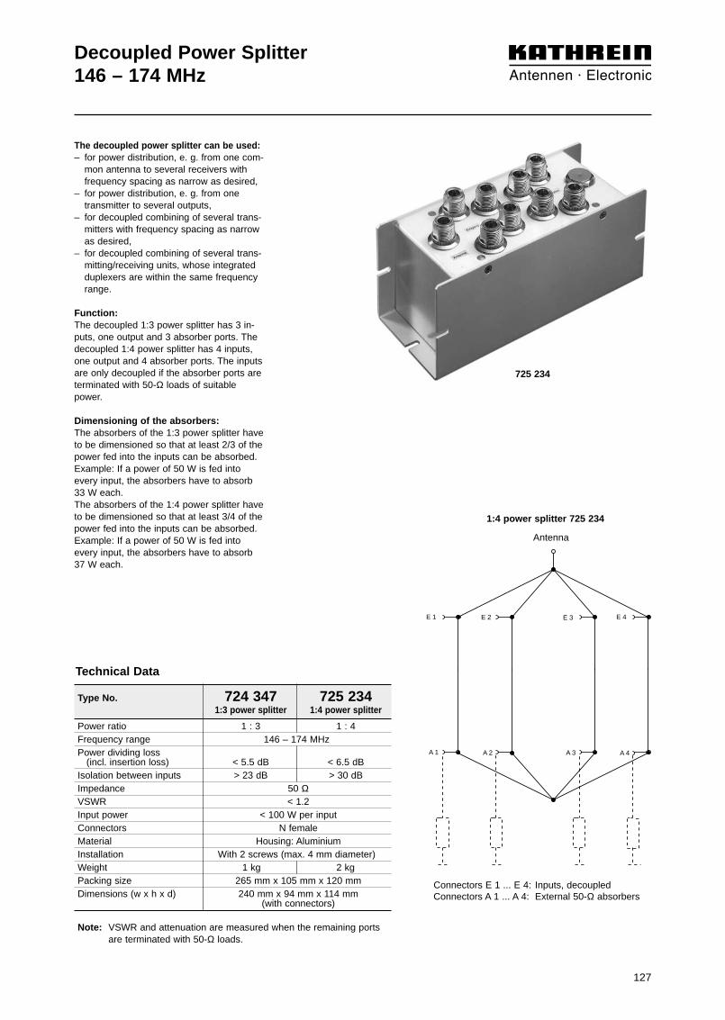
127
Decoupled Power Splitter 146 – 174 MHz
1:4 power splitter 725 234
A 4A 3A 2A 1
E 1 E 2 E 3 E 4
Antenna
Type No. 724 347 725 2341:3 power splitter 1:4 power splitter
Power ratio 1 : 3 1 : 4Frequency range 146 – 174 MHzPower dividing loss
(incl. insertion loss) < 5.5 dB < 6.5 dBIsolation between inputs > 23 dB > 30 dBImpedance 50 ΩVSWR < 1.2Input power < 100 W per inputConnectors N femaleMaterial Housing: AluminiumInstallation With 2 screws (max. 4 mm diameter)Weight 1 kg 2 kgPacking size 265 mm x 105 mm x 120 mmDimensions (w x h x d) 240 mm x 94 mm x 114 mm
(with connectors)
Note: VSWR and attenuation are measured when the remaining ports are terminated with 50-Ω loads.
Technical Data
The decoupled power splitter can be used:– for power distribution, e. g. from one com-
mon antenna to several receivers withfrequency spacing as narrow as desired,
– for power distribution, e. g. from one transmitter to several outputs,
– for decoupled combining of several trans-mitters with frequency spacing as narrow as desired,
– for decoupled combining of several trans-mitting/receiving units, whose integrated duplexers are within the same frequency range.
Function:The decoupled 1:3 power splitter has 3 in-puts, one output and 3 absorber ports. Thedecoupled 1:4 power splitter has 4 inputs,one output and 4 absorber ports. The inputsare only decoupled if the absorber ports areterminated with 50-Ω loads of suitablepower.
Dimensioning of the absorbers:The absorbers of the 1:3 power splitter haveto be dimensioned so that at least 2/3 of thepower fed into the inputs can be absorbed. Example: If a power of 50 W is fed intoevery input, the absorbers have to absorb33 W each.The absorbers of the 1:4 power splitter haveto be dimensioned so that at least 3/4 of thepower fed into the inputs can be absorbed.Example: If a power of 50 W is fed intoevery input, the absorbers have to absorb37 W each.
Connectors E 1 ... E 4: Inputs, decoupledConnectors A 1 ... A 4: External 50-Ω absorbers
725 234

128
3
12
Circulator146 – 174 MHz
deep
deep
Type No. 793 277Frequency range 146 – 174 MHzInsertion loss 1 → 2 < 0.5Isolation 2 → 1 > 20 dBVSWR 1, 2, 3 < 1.22Impedance 50 ΩInput power < 100 WTemperature range –10 … +55 °CConnectors N femaleWeight 660 gPacking size 150 mm x 115 mm x 105 mmDimensions (w x h x d) 105 mm x 87 mm x 32 mm
(with connectors)
Technical Data
The circulator can be used:– to increase the coupling attenuation
between transmitters, to reduce inter-modulation products,
– to prevent adverse effects of unmatched load impedance on amplifier perfor-mance.
Function:The circulator is a nonreciprocal compo-nent with low insertion loss in the forwarddirection (1 → 2) and high attenuation inthe reverse direction (2 → 1). The impe-dance at the input (1) of the circulator isconstant and independent of the impedan-ce of the components following. The reflec-ted power at output (2) is passed to theabsorber port (3), which must be termina-ted with an absorber.
Dimensioning of the absorber:The absorber at port (3) must be dimensio-ned to be able to absorb the maximumpower reflected at output (2).
793 277
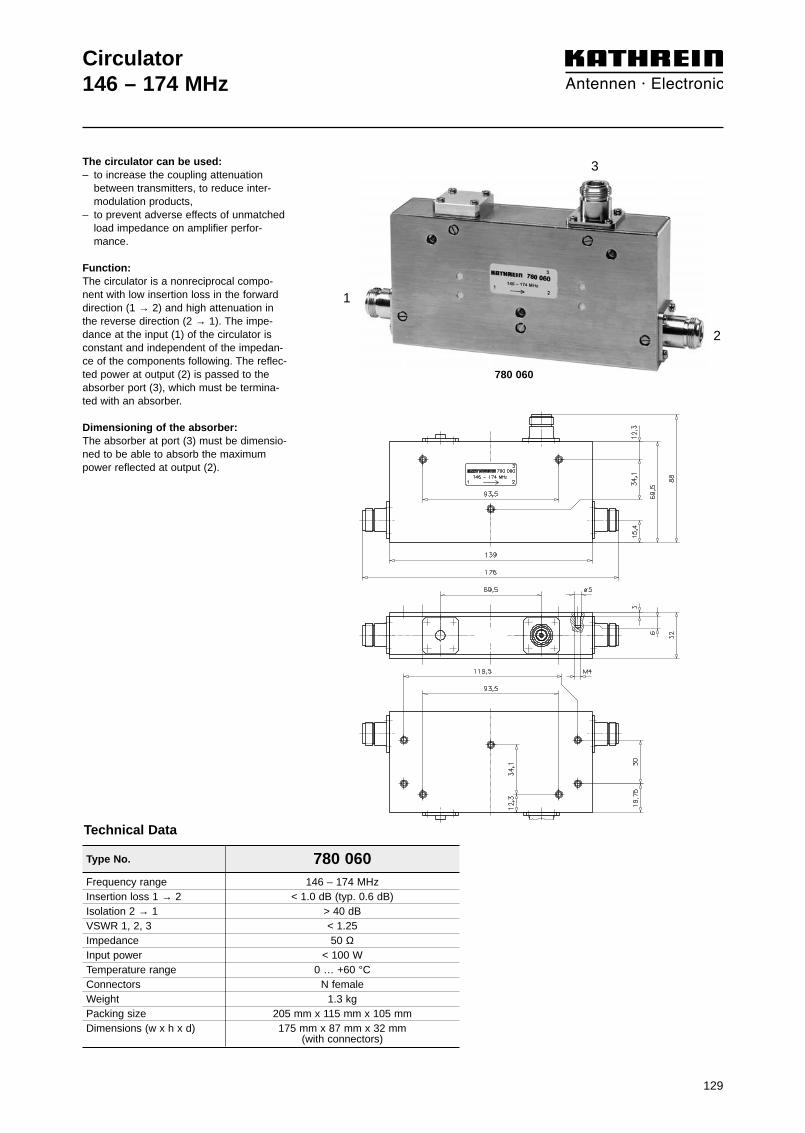
129
Circulator146 – 174 MHz
1
3
2
Type No. 780 060Frequency range 146 – 174 MHzInsertion loss 1 → 2 < 1.0 dB (typ. 0.6 dB)Isolation 2 → 1 > 40 dBVSWR 1, 2, 3 < 1.25Impedance 50 ΩInput power < 100 WTemperature range 0 … +60 °CConnectors N femaleWeight 1.3 kgPacking size 205 mm x 115 mm x 105 mmDimensions (w x h x d) 175 mm x 87 mm x 32 mm
(with connectors)
Technical Data
The circulator can be used:– to increase the coupling attenuation
between transmitters, to reduce inter-modulation products,
– to prevent adverse effects of unmatched load impedance on amplifier perfor-mance.
Function:The circulator is a nonreciprocal compo-nent with low insertion loss in the forwarddirection (1 → 2) and high attenuation inthe reverse direction (2 → 1). The impe-dance at the input (1) of the circulator isconstant and independent of the impedan-ce of the components following. The reflec-ted power at output (2) is passed to theabsorber port (3), which must be termina-ted with an absorber.
Dimensioning of the absorber:The absorber at port (3) must be dimensio-ned to be able to absorb the maximumpower reflected at output (2).
780 060
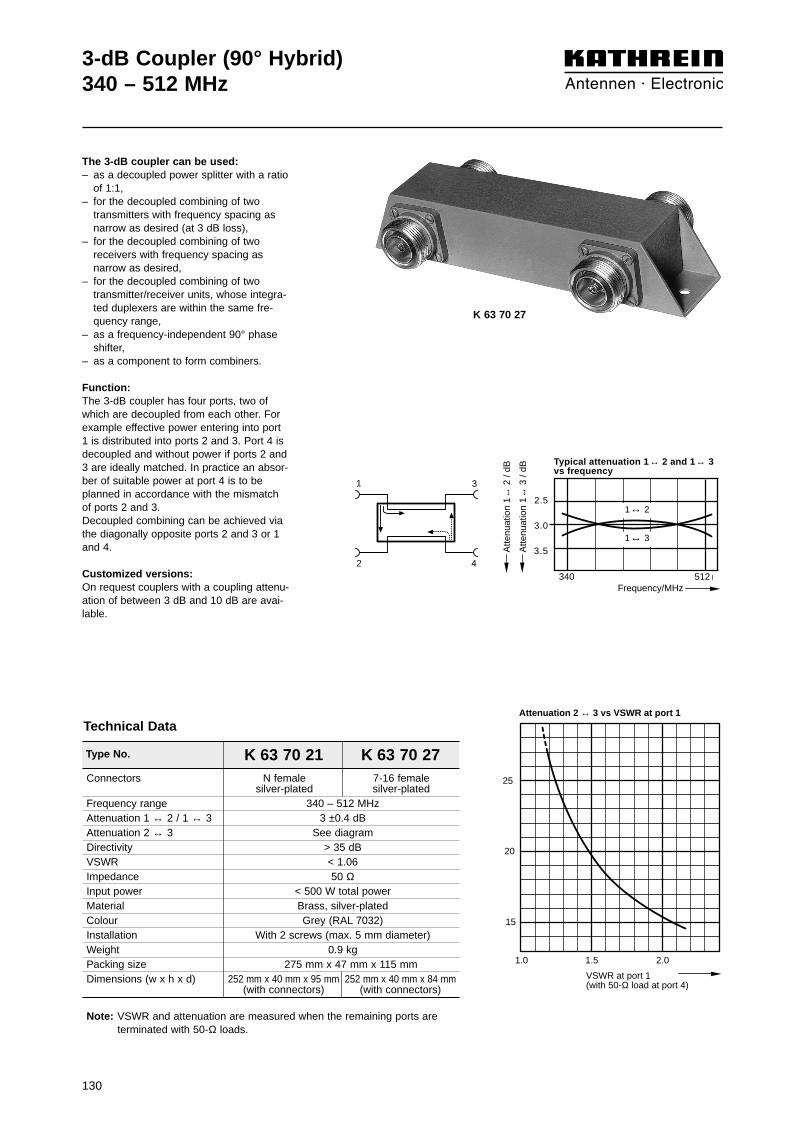
Connectors N female 7-16 femalesilver-plated silver-plated
Frequency range 340 – 512 MHzAttenuation 1 ↔ 2 / 1 ↔ 3 3 ±0.4 dBAttenuation 2 ↔ 3 See diagramDirectivity > 35 dBVSWR < 1.06Impedance 50 ΩInput power < 500 W total powerMaterial Brass, silver-platedColour Grey (RAL 7032)Installation With 2 screws (max. 5 mm diameter)Weight 0.9 kgPacking size 275 mm x 47 mm x 115 mmDimensions (w x h x d) 252 mm x 40 mm x 95 mm 252 mm x 40 mm x 84 mm
(with connectors) (with connectors)
Note: VSWR and attenuation are measured when the remaining ports are terminated with 50-Ω loads.
3-dB Coupler (90° Hybrid)340 – 512 MHz
Type No. K 63 70 21 K 63 70 27
Technical Data
The 3-dB coupler can be used:– as a decoupled power splitter with a ratio
of 1:1,– for the decoupled combining of two
transmitters with frequency spacing asnarrow as desired (at 3 dB loss),
– for the decoupled combining of tworeceivers with frequency spacing as narrow as desired,
– for the decoupled combining of twotransmitter/receiver units, whose integra-ted duplexers are within the same fre-quency range,
– as a frequency-independent 90° phaseshifter,
– as a component to form combiners.
Function:The 3-dB coupler has four ports, two ofwhich are decoupled from each other. Forexample effective power entering into port1 is distributed into ports 2 and 3. Port 4 isdecoupled and without power if ports 2 and3 are ideally matched. In practice an absor-ber of suitable power at port 4 is to beplanned in accordance with the mismatchof ports 2 and 3.Decoupled combining can be achieved viathe diagonally opposite ports 2 and 3 or 1and 4.
Customized versions:On request couplers with a coupling attenu-ation of between 3 dB and 10 dB are avai-lable.
2.5
3.0
3.5
Frequency/MHz
1 ↔ 2
1 ↔ 3
806 960
Typical attenuation 1 ↔ 2 and 1 ↔ 3vs frequency
Atte
nuat
ion
1 ↔
3 /
dB
Atte
nuat
ion
1 ↔
2 /
dB
1 3
2 4
1.0 1.5 2.0
15
20
25
VSWR at port 1(with 50-Ω load at port 4)
Attenuation 2 ↔ 3 vs VSWR at port 1
340 512
130
K 63 70 27
131
4.7-dB, 6-dB, 7-dB, 10-dB Coupler (90° Hybrid)380 – 470 MHz
1 3
2 4
Type No. N female 719 782 792 777 792 331 720 2977-16 female 722 488 790 589 790 590 720 942
Version 4.7-dB coupler 6-dB coupler 7-dB coupler 10-dB couplerFrequency range 380 – 470 MHzAttenuation 1↔3 (4↔2) 1.8 ±0.3 dB 1.25 ±0.2 dB 1.0 ±0.2 dB 0.5 ±0.2 dBAttenuation 1↔2 (4↔3) 4.7 ±0.5 dB 6.0 ±0.5 dB 7.0 ±0.5 dB 10 ±0.5 dBDirectivity > 30 dB > 30 dB > 30 dB > 27 dBVSWR < 1.1Impedance 50 ΩInput power < 500 W Connectors Silver-platedMaterial Brass, silver-platedColour Grey (RAL 7032)Installation With 2 screws (max. 5 mm diameter)Weight 1.0 kgPacking size 275 mm x 47 mm x 115 mm Dimensions
N female (w x h x d) 252 mm x 40 mm x 95 mm (with connectors)7-16 female (w x h x d) 252 mm x 40 mm x 84 mm (with connectors)
Note: VSWR and attenuation are measured when the remaining ports are terminated with 50-Ω loads.
Technical Data
The 4.7-dB coupler is used as a decoupled splitterfor power splitting purposes at a 1 : 2 ratio. An effective power entering into e.g. port 1 is divi-ded between the ports 2 and 3 at a ratio of 1 : 2. Thus 1/3 of the input power (attenuation: 4.7 dB) isavailable at port 2 and 2/3 of the input power isavailable at port 3.
The 6-dB coupler is used as a decoupled splitterfor power splitting purposes at a 1 : 3 ratio. An effective power entering into e.g. port 1 is divi-ded between the ports 2 and 3 at a ratio of 1 : 3. Thus 1/4 of the input power (attenuation: 6 dB) isavailable at port 2 and 3/4 of the input power isavailable at port 3.
The 7-dB coupler is used as a decoupled splitterfor power splitting purposes at a 1 : 4 ratio. An effective power entering into e.g. port 1 is divi-ded between the ports 2 and 3 at a ratio of 1 : 4. Thus 1/5 of the input power (attenuation: 7 dB) isavailable at port 2 and 4/5 of the input power isavailable at port 3.
The 10-dB coupler is used as a decoupled splitterfor power splitting purposes at a 1 : 9 ratio. An effective power entering at e.g. port 1 is dividedbetween the ports 2 and 3 at a ratio of 1 : 9.Thus 1/10 of the input power (attenuation: 10 dB) is available at port 2 and 9/10 of the input power isavailable at port 3.
Port 4 is decoupled and remains free of power ifthe ports 2 and 3 are ideally matched. In practicean absorber of suitable power at port 4 is to beplanned in accordance with the mismatch of ports 2 and 3.
Decoupled combining can be achieved via the dia-gonally opposite ports 2 and 3 respectively 1 and 4.
722 488790 589790 590720 942

4
3
1
2
λ/4 λ/4
3/4λ λ/4
12
34
Hybrid Ring Junction (180° Hybrid)380 – 430 MHzTETRA, TETRAPOL
The hybrid ring junction can be used:– as a power splitter with a ratio of 1:1,– for the decoupled combining of two
transmitters with arbitrarily low frequencyspacing (at 3 dB loss),
– for the decoupled combining of tworeceivers with arbitrarily low frequencyspacing,
– for the decoupled combining of twotransmitter/ receiver units, whose intgra-ted duplexers are within the same frequency range,
– as component to form combiners.
Description:The hybrid ring junction has four ports, twoof which are decoupled from each other.For example effective power entering intoport 1 is distributed into ports 2 and 4, port3 is decoupled and without power if ports 2and 4 are ideally matched. In practice anabsorber of suitable power at port 3 is to beplanned for according to the mismatch ofports 2 and 4.Decoupled combining can be made via port 1 and 3 or 2 and 4.
132
Frequency range 380 – 430 MHzAttenuation 1↔2 bzw. 1↔4 3 ±0.4 dBAttenuation 1↔3 bzw. 2↔4 See diagramsVSWR* < 1.2Impedance 50 ΩInput power < 100 W per InputConnector N femaleMaterial Housing: AluminiumInstallation With 2 screws (M4)Weight 500 gPacking size 230 mm x 35 mm x 130 mmDimensions (w x h x d) 225 mm x 32 mm x 117 mm
(with connectors)
Note: VSWR and attenuation are measured when the remaining ports are terminated with 50-Ω loads.
Type No. 730 092
Technical Data
20
Atte
nuat
ion
2↔4
/ dB
Atte
nuat
ion
1↔3
/ dB
30
40
Attenuation 1↔3 or 2↔4 vs frequency
Frequency/MHz
370
typical attenuationguaranteed values
390 410 450380 430
The remaining ports are terminated with 50-Ω loads.
1↔4
1↔2
2.5
3.0
3.5
Frequency/MHz380 430
Typical attenuation 1↔2 and 1↔4vs frequency
Atte
nuat
ion
1↔4
/ dB
Atte
nuat
ion
1↔2
/ dB
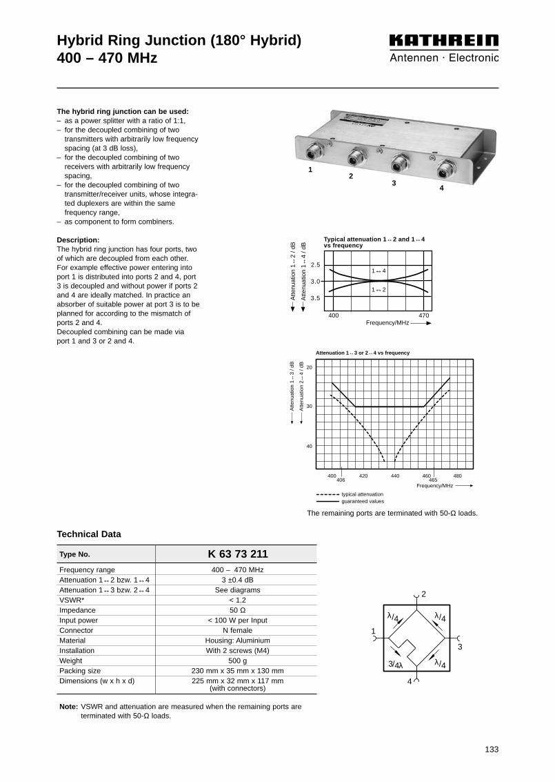
4
3
1
2
λ/4 λ/4
3/4λ λ/4
12
34
133
1↔4
1↔2
2.5
3.0
3.5
Frequency/MHz400 470
Typical attenuation 1↔2 and 1↔4vs frequency
Atte
nuat
ion
1↔4
/ dB
Atte
nuat
ion
1↔2
/ dB
20
Atte
nuat
ion
2↔4
/ dB
Atte
nuat
ion
1↔3
/ dB
30
40
Attenuation 1↔3 or 2↔4 vs frequency
Frequency/MHz
400
typical attenuationguaranteed values
420 440 460 480406 465
The remaining ports are terminated with 50-Ω loads.
Hybrid Ring Junction (180° Hybrid)400 – 470 MHz
Frequency range 400 – 470 MHzAttenuation 1↔2 bzw. 1↔4 3 ±0.4 dBAttenuation 1↔3 bzw. 2↔4 See diagramsVSWR* < 1.2Impedance 50 ΩInput power < 100 W per InputConnector N femaleMaterial Housing: AluminiumInstallation With 2 screws (M4)Weight 500 gPacking size 230 mm x 35 mm x 130 mmDimensions (w x h x d) 225 mm x 32 mm x 117 mm
(with connectors)
Note: VSWR and attenuation are measured when the remaining ports are terminated with 50-Ω loads.
Type No. K 63 73 211
Technical Data
The hybrid ring junction can be used:– as a power splitter with a ratio of 1:1,– for the decoupled combining of two
transmitters with arbitrarily low frequencyspacing (at 3 dB loss),
– for the decoupled combining of tworeceivers with arbitrarily low frequencyspacing,
– for the decoupled combining of twotransmitter/receiver units, whose integra-ted duplexers are within the same frequency range,
– as component to form combiners.
Description:The hybrid ring junction has four ports, twoof which are decoupled from each other.For example effective power entering intoport 1 is distributed into ports 2 and 4, port3 is decoupled and without power if ports 2and 4 are ideally matched. In practice anabsorber of suitable power at port 3 is to beplanned for according to the mismatch ofports 2 and 4.Decoupled combining can be made via port 1 and 3 or 2 and 4.

134
Decoupled Power Splitter 380 – 430 MHzTETRA, TETRAPOL
The decoupled power splitter can be used:– for power distribution. For example: From
one common antenna to several receiversof arbitrarily low frequency spacing,
– for power distribution. For example: From one transmitter to several outputs,
– for decoupled combining of several trans-mitters with arbitrarily low frequency spacing (loss: 4.7 dB resp. 6 dB),
– for decoupled combining of several trans-mitting/receiving units, whose integrated duplexers are within the same frequency range.
Function:The decoupled power splitter has 3 or 4inputs, one output, as well as 3 or 4 absor-ber ports. The inputs are only decoupledwhen the absorber ports are terminated with50-Ω loads of suitable power.
The absorbers of the 3:1-power splitter haveto be dimensioned so that at least 2/3 of thepower fed into the inputs can be absorbed. Example: If a power of 50 W is fed intoevery input, the absorbers have to absorb33 W each.
The absorbers of the 4:1 power splitter haveto be dimensioned so that at least 3/4 of thepower fed into the inputs can be absorbed.Example: If a power of 50 W is fed intoevery input, the absorbers have to absorb37 W each.
Power ratio 1 : 3 1 : 4Frequency range 380 – 430 MHzPower dividing loss
(incl. insertion loss) < 5.5 dB < 6.5 dBIsolation between inputs > 25 dB > 30 dBImpedance 50 ΩVSWR < 1.2Input power < 100 W per inputConnectors N femaleMaterial Housing: AluminiumInstallation With 2 screws
(max. 4 mm diameter)Weight 1.0 kg 1.5 kgPacking size 220 mm x 90 mm x 110 mmDimensions (w x h x d) 190 mm x 80 mm x 94 mm
(with connectors)
Technical Data
A 4A 3A 2A 1
E 1 E 2 E 3 E 4
Output(Antenna)
1 : 4 power splitter 782 10189
Type No. 782 10231 782 101891 : 3 Power splitter 1 : 4 Power splitter
Connectors E 1 ... E 4: Inputs, decoupledConnectors A 1 ... A 4: External 50-Ω absorbers
782 10189

135
Decoupled Power Splitter 400 – 470 MHz
The decoupled power splitter can be used:– for power distribution. For example: From
one common antenna to several receiversof arbitrarily low frequency spacing,
– for power distribution. For example: From one transmitter to several outputs,
– for decoupled combining of several trans-mitters with arbitrarily low frequency spacing (loss: 4.7 dB resp. 6 dB),
– for decoupled combining of several trans-mitting/receiving units, whose integrated duplexers are within the same frequency range.
Function:The decoupled power splitter has 3 or 4inputs, one output, as well as 3 or 4 absor-ber ports. The inputs are only decoupledwhen the absorber ports are terminated with50-Ω loads of suitable power.
The absorbers of the 3:1-power splitter haveto be dimensioned so that at least 2/3 of thepower fed into the inputs can be absorbed. Example: If a power of 50 W is fed intoevery input, the absorbers have to absorb33 W each.
The absorbers of the 4:1 power splitter haveto be dimensioned so that at least 3/4 of thepower fed into the inputs can be absorbed.Example: If a power of 50 W is fed intoevery input, the absorbers have to absorb37 W each.
Power ratio 1 : 3 1 : 4Frequency range 400 – 470 MHzPower dividing loss
(incl. insertion loss) < 5.5 dB < 6.5 dBIsolation between inputs > 25 dB > 30 dBImpedance 50 ΩVSWR < 1.2Input power < 100 W per inputConnectors N femaleMaterial Housing: AluminiumInstallation With 2 screws
(max. 4 mm diameter)Weight 1.0 kg 1.5 kgPacking size 220 mm x 90 mm x 110 mmDimensions (w x h x d) 190 mm x 80 mm x 94 mm
(with connectors)
Technical Data
A 4A 3A 2A 1
E 1 E 2 E 3 E 4
Output(Antenna)
1 : 4 power splitter 725 871
Type No. 724 348 725 8711 : 3 Power splitter 1 : 4 Power splitter
Connectors E 1 ... E 4: Inputs, decoupledConnectors A 1 ... A 4: External 50-Ω absorbers
725 871

136
Type No. 784 10175 790 215
Circulator380 – 430 MHz (TETRA, TETRAPOL)400 – 470 MHz
Frequency range 380 – 430 MHz 400 – 470 MHzInsertion loss 1 → 2 < 0.5 dB (typ. 0.4 dB) < 0.5 dB (typ. 0.3 dB)Isolation 2 → 1 > 45 dB > 50 dBVSWR 1, 2, 3 < 1.19 < 1.22Impedance 50 Ω 50 ΩInput power < 200 W < 100 WTemperature range –10 … +55 °CConnectors N femaleMounting With 2 screws (M3)Weight 635 gPacking size 160 mm x 90 mm x 40 mmDimensions (w x h x d) 96 mm x 50 mm x 26 mm
(without connectors)
Technical Data
The circulator can be used:– to increase the coupling attenuation
between transmitters, to reduce inter-modulation products,
– to prevent adverse effects of unmatched load impedance on amplifier performance.
Function:Circulators are nonreciprocal componentswith low insertion loss in the forward direc-tion (1 → 2) and high attenuation in the re-verse direction (2 → 1). The impedance atthe input (1) of the circulator is constantand independent of the impedance of thecomponents following, since the reflectedpower is passed to the absorber port (3).
1
2
3
784 10175790 215

Type No. 791 630
Circulator400 – 470 MHz
Frequency range 400 – 470 MHzInsertion loss 1 → 2 < 0.3 dBIsolation 2 → 1 > 23 dBVSWR 1, 2, 3 < 1.17Impedance 50 ΩInput power < 100 WTemperature range –10 … +55 °CConnectors N femaleMounting With 2 screws (M3)Weight 380 gPacking size 110 mm x 100 mm x 40 mmDimensions (w x h x d) 51 mm x 51 mm x 26 mm
(without connectors)
Technical Data
The circulator can be used:– to increase the coupling attenuation
between transmitters, to reduce inter-modulation products,
– to prevent adverse effects of unmatched load impedance on amplifier performance.
Function:Circulators are nonreciprocal componentswith low insertion loss in the forward direc-tion (1 → 2) and high attenuation in the reverse direction (2 → 1). The impedanceat the input (1) of the circulator is constantand independent of the impedance of thecomponents following, since the reflectedpower is passed to the absorber port (3). 791 630
1
2
3
137
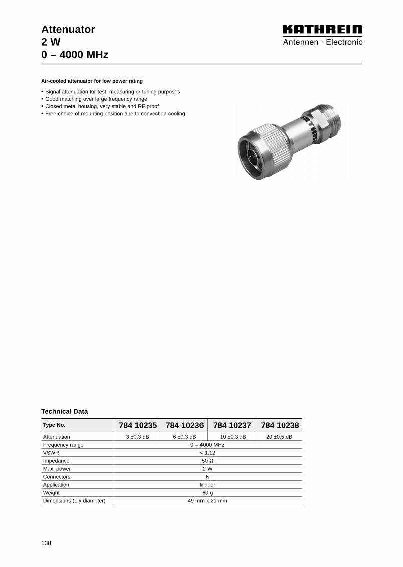
Attenuator2 W0 – 4000 MHz
Type No. 784 10235 784 10236 784 10237 784 10238Attenuation 3 ±0.3 dB 6 ±0.3 dB 10 ±0.3 dB 20 ±0.5 dB
Frequency range 0 – 4000 MHz
VSWR < 1.12
Impedance 50 ΩMax. power 2 W
Connectors N
Application Indoor
Weight 60 g
Dimensions (L x diameter) 49 mm x 21 mm
Technical Data
Air-cooled attenuator for low power rating
• Signal attenuation for test, measuring or tuning purposes• Good matching over large frequency range• Closed metal housing, very stable and RF proof• Free choice of mounting position due to convection-cooling
138

139
Attenuator10 W / 12 W / 15 W0 – 4000 MHz
Type No. 791 918 791 919 791 920 791 921Attenuation 3 ±0.3 dB 6 ±0.3 dB 10 ±0.3 dB 20 ±0.5 dB
Max. power 15 W 12 W 10 W 10 W
Frequency range 0 – 4000 MHz
VSWR < 1.15
Impedance 50 ΩConnectors N
Application Indoor
Weight 70 g
Dimensions (L x diameter) 50 mm x 26 mm
Technical Data
Air-cooled attenuator for medium power rating
• Signal attenuation for test, measuring or tuning purposes• Good matching over large frequency range• Closed metal housing, very stable and RF proof• Free choice of mounting position due to convection-cooling
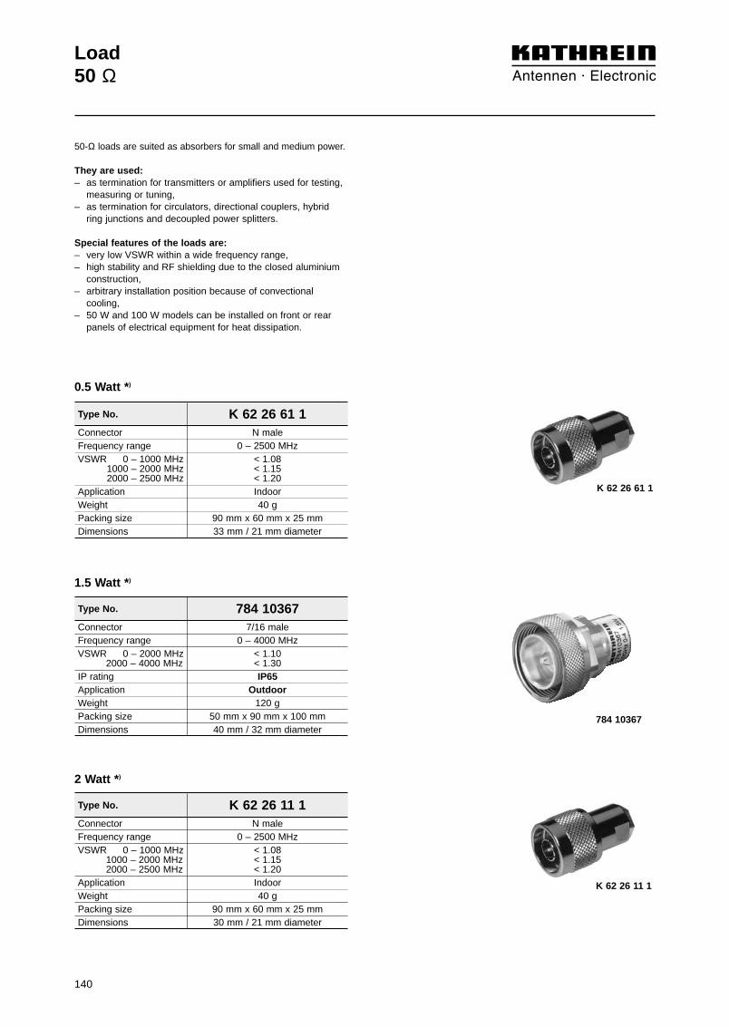
140
Load50 Ω
50-Ω loads are suited as absorbers for small and medium power.
They are used:– as termination for transmitters or amplifiers used for testing,
measuring or tuning,– as termination for circulators, directional couplers, hybrid
ring junctions and decoupled power splitters.
Special features of the loads are:– very low VSWR within a wide frequency range,– high stability and RF shielding due to the closed aluminium
construction,– arbitrary installation position because of convectional
cooling,– 50 W and 100 W models can be installed on front or rear
panels of electrical equipment for heat dissipation.
Type No. K 62 26 61 1Connector N maleFrequency range 0 – 2500 MHzVSWR 0 – 1000 MHz < 1.08VSWR1000 – 2000 MHz < 1.15VSWR2000 – 2500 MHz < 1.20Application IndoorWeight 40 gPacking size 90 mm x 60 mm x 25 mmDimensions 33 mm / 21 mm diameter
0.5 Watt *)
Type No. 784 10367Connector 7/16 maleFrequency range 0 – 4000 MHzVSWR 0 – 2000 MHz < 1.10
VSWR 2000 – 4000 MHz < 1.30IP rating IP65Application OutdoorWeight 120 gPacking size 50 mm x 90 mm x 100 mmDimensions 40 mm / 32 mm diameter
1.5 Watt *)
K 62 26 61 1
784 10367
Type No. K 62 26 11 1Connector N maleFrequency range 0 – 2500 MHzVSWR 0 – 1000 MHz < 1.08
VSWR 1000 – 2000 MHz < 1.15VSWR 2000 – 2500 MHz < 1.20Application IndoorWeight 40 gPacking size 90 mm x 60 mm x 25 mmDimensions 30 mm / 21 mm diameter
2 Watt *)
K 62 26 11 1
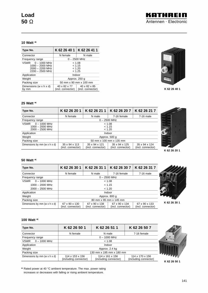
141
Load50 Ω
*) Rated power at 40 °C ambient temperature. The max. power rating increases or decreases with falling or rising ambient temperature.
Type No. K 62 26 30 1 K 62 26 31 1 K 62 26 30 7 K 62 26 31 7Connector N female N male 7-16 female 7-16 maleFrequency range 0 – 2500 MHzVSWR 0 – 1000 MHz < 1.08VSWR1000 – 2000 MHz < 1.15VSWR2000 – 2500 MHz < 1.20Application IndoorWeight Approx. 800 gPacking size 80 mm x 95 mm x 145 mmDimensions by mm (w x h x d) 67 x 90 x 130 67 x 90 x 138 67 x 90 x 134 67 x 90 x 133
(incl. connector) (incl. connector) (incl. connector) (incl. connector)
50 Watt *)
Type No. K 62 26 50 1 K 62 26 51 1 K 62 26 50 7Connector N female N male 7-16 femaleFrequency range 0 – 1000 MHzVSWR 0 – 1000 MHz < 1.08Application IndoorWeight Approx. 2.4 kgPacking size 130 mm x 195 mm x 180 mmDimensions by mm (w x h x d) 114 x 153 x 156 114 x 161 x 156 114 x 170 x 156
(including connector) (including connector) (including connector)
100 Watt *)
Type No. K 62 26 20 1 K 62 26 21 1 K 62 26 20 7 K 62 26 21 7Connector N female N male 7-16 female 7-16 maleFrequency range 0 – 2500 MHzVSWR 0 – 1000 MHz < 1.08VSWR1000 – 2000 MHz < 1.15VSWR2000 – 2500 MHz < 1.20Application IndoorWeight Approx. 500 gPacking size 50 mm x 100 mm x 135 mmDimensions by mm (w x h x d) 35 x 94 x 113 35 x 94 x 121 35 x 94 x 125 35 x 94 x 124
(incl. connector) (incl. connector) (incl. connector) (incl. connector)
25 Watt *)
K 62 26 30 1
K 62 26 50 1
K 62 26 20 1
Type No. K 62 26 40 1 K 62 26 41 1Connector N female N maleFrequency range 0 – 2500 MHzVSWR 0 – 1000 MHz < 1.08
V 1000 – 2000 MHz < 1.15VSW R2000 – 2200 MHz < 1.20VSW R2200 – 2500 MHz < 1.25Application IndoorWeight Approx. 250 gPacking size 50 mm x 90 mm x 100 mmDimensions (w x h x d) 40 x 82 x 77 40 x 82 x 85by mm (incl. connector) (incl. connector)
10 Watt *)
K 62 26 40 1

142

143
Active Multicouplers68 – 87.5 MHz146 – 174 MHz380 – 470 MHz
Act
ive
Mu
ltic
ou
ple
rs

144

Summary of Articles
Receiver Multicouplers:
Receiver Multicoupler 780 234 68 – 87.5 MHz 3 dB 8 146
Receiver Multicoupler 780 235 68 – 87.5 MHz 1 dB 16 147
Receiver Multicoupler 780 232 146 – 174 MHz 3 dB 8 148
Receiver Multicoupler 780 233 146 – 174 MHz 1 dB 16 149
Receiver Multicoupler 727 621 380 – 470 MHz 3 dB 8 150
Receiver Multicoupler 727 622 380 – 470 MHz 1 dB 16 151
Description Type No. Frequency range Gain Outputs Page... tunable bandwidth– fixed bandwidth (not tunable)
145
Active Duplex Multicouplers:
Active Duplex Multicoupler K 60 21 41 12 A 68 ... 87.5 MHz +1.7 dB / 2 x 10 W 2 152
Active Duplex Multicoupler K 60 21 41 12 B 68 ... 87.5 MHz +1.7 dB / 2 x 10 W 2 152
Active Duplex Multicoupler K 60 21 41 A 68 ... 87.5 MHz 0 dB / 3 x 10 W 3 152
Active Duplex Multicoupler K 60 21 41 B 68 ... 87.5 MHz 0 dB / 3 x 10 W 3 152
Active Duplex Multicoupler K 60 21 41 14 A 68 ... 87.5 MHz –1.3 dB / 4 x 10 W 4 152
Active Duplex Multicoupler K 60 21 41 14 B 68 ... 87.5 MHz –1.3 dB / 4 x 10 W 4 152
Active Duplex Multicoupler K 60 21 41 15 A 68 ... 87.5 MHz –2.3 dB / 5 x 10 W 5 152
Active Duplex Multicoupler K 60 21 41 15 B 68 ... 87.5 MHz –2.3 dB / 5 x 10 W 5 152
Active Duplex Multicoupler K 60 21 21 12 A 146 ... 174 MHz +1.7 dB / 2 x 10 W 2 153
Active Duplex Multicoupler K 60 21 21 12 B 146 ... 174 MHz +1.7 dB / 2 x 10 W 2 153
Active Duplex Multicoupler K 60 21 21 A 146 ... 174 MHz 0 dB / 3 x 10 W 3 153
Active Duplex Multicoupler K 60 21 21 B 146 ... 174 MHz 0 dB / 3 x 10 W 3 153
Active Duplex Multicoupler K 60 21 21 14 A 146 ... 174 MHz –1.3 dB / 4 x 10 W 4 153
Active Duplex Multicoupler K 60 21 21 14 B 146 ... 174 MHz –1.3 dB / 4 x 10 W 4 153
Active Duplex Multicoupler K 60 21 21 15 A 146 ... 174 MHz –2.3 dB / 5 x 10 W 5 153
Active Duplex Multicoupler K 60 21 21 15 B 146 ... 174 MHz –2.3 dB / 5 x 10 W 5 153
Description Type No. Frequency range Gain / Input power Inputs Page... tunable bandwidth– fixed bandwidth (not tunable)

146
Receiver Multicoupler 68 – 87.5 MHz
Front side
Rear side
Type No. 780 234Number of inputs 1Number of outputs 8Frequency range 68 – 87.5 MHzGain 3.0 dB (+1.5 / –1.5 dB)Noise figure < 4.0 dB (+0.5 dB)3rd order intercept point > 23 dBm (typ. 25 dBm)Isolation > 25 dB (typ. 30 dB) between any two outputsVSWR Input < 1.4
Output < 1.4Impedance 50 ΩPower supply 230 V ~ (+10 / –15 %), 50 … 60 Hz and/or
11 … 48 V =, floatingPower consumption < 9 W (230 V ~, 50 Hz)
< 20 W (11 … 48 V =)Temperature range –20 … +55 °CConnectors N femaleColour Front panel: Grey (RAL 7032)Attached hardware Power cable and 4 pin DC connectorWeight 3.9 kgPacking size 560 mm x 105 mm x 385 mmDimensions (w x h x d) 483 mm x 44 mm x 280 mm, 19˝ drawer
Note: Not used outputs have to be terminated using a 50-Ω load in order tocomply with the specifications.
Technical Data
This receiver multicoupler makes it possibleto operate up to 8 receivers simultaneouslyon one common antenna. It is especially suitable for use at base stations wherethere is only limited mast space for thereceiving antennas.The low noise level and the excellent inter-modulation characteristics of the receivermulticoupler ensure a high dynamic range.
The receiver multicoupler consists of:– a low noise amplifier,– a power splitter,– a voltage supply.
The RF signals are amplified at the input ofthe receiver multicoupler by an activelyredundant low noise amplifier. This meansthat the receiver multicoupler will stillremain operational even if one of the paral-lel connected amplifier modules fails. In thiscase, however, the gain will decrease byabout 6 dB.Each amplifier module has its own voltagesupply which is so designed that the modu-les can be operated simultaneously withboth alternating current (230 V ~) anddirect current (11 ... 48 V =).
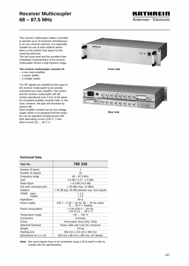
147
Receiver Multicoupler 68 – 87.5 MHz
Rear side
Front side
This receiver multicoupler makes it possibleto operate up to 16 receivers simultaneous-ly on one common antenna. It is especiallysuitable for use at base stations wherethere is only limited mast space for thereceiving antennas.The low noise level and the excellent inter-modulation characteristics of the receivermulticoupler ensure a high dynamic range.
The receiver multicoupler consists of:– a low noise amplifier,– a power splitter,– a voltage supply.
The RF signals are amplified at the input ofthe receiver multicoupler by an activelyredundant low noise amplifier. This meansthat the receiver multicoupler will stillremain operational even if one of the paral-lel connected amplifier modules fails. In thiscase, however, the gain will decrease byabout 6 dB.Each amplifier module has its own voltagesupply which is so designed that the modu-les can be operated simultaneously withboth alternating current (230 V ~) anddirect current (11 ... 48 V =).
Type No. 780 235Number of inputs 1Number of outputs 16Frequency range 68 – 87.5 MHzGain 1.0 dB (+1.5 / –1.5 dB)Noise figure < 4.5 dB (+0.5 dB)3rd order intercept point > 20 dBm (typ. 22 dBm)Isolation > 25 dB (typ. 30 dB) between any two outputsVSWR Input < 1.4
Output < 1.4Impedance 50 ΩPower supply 230 V ~ (+10 / –15 %), 50 … 60 Hz and/or
11 … 48 V =, floatingPower consumption < 9 W (230 V ~, 50 Hz)
< 20 W (11 … 48 V =)Temperature range –20 … +55 °CConnectors N femaleColour Front panel: Grey (RAL 7032)Attached hardware Power cable and 4 pin DC connectorWeight 5.9 kgPacking size 560 mm x 115 mm x 385 mmDimensions (w x h x d) 483 mm x 88 mm x 280 mm, 19˝ drawer
Note: Not used outputs have to be terminated using a 50-Ω load in order tocomply with the specifications.
Technical Data

148
Type No. 780 232
Receiver Multicoupler 146 – 174 MHz
Number of inputs 1Number of outputs 8Frequency range 146 – 174 MHzGain 3.0 dB (+1.5 / –1.5 dB)Noise figure < 4.0 dB (+0.5 dB)3rd order intercept point > 23 dBm (typ. 25 dBm)Isolation > 25 dB (typ. 30 dB) between any two outputs VSWR Input < 1.4VSWR Output < 1.4Impedance 50 ΩPower supply 230 V ~ (+10 / –15 %), 50 … 60 Hz and/or
11 … 48 V =, floatingPower consumption < 9 W (230 V ~, 50 Hz)
< 20 W (11 … 48 V =)Temperature range –20 … +55 °CConnectors N femaleColour Front panel: Grey (RAL 7032)Attached hardware Power cable and 4 pin DC connectorWeight 3.9 kgPacking size 560 mm x 105 mm x 385 mmDimensions (w x h x d) 483 mm x 44 mm x 280 mm, 19˝ drawer
Note: Not used outputs have to be terminated using a 50-Ω load in order to comply with the specifications.
Technical Data
Rear side
This receiver multicoupler makes it possibleto operate up to 8 receivers simultaneouslyon one common antenna. It is especially suitable for use at base stations wherethere is only limited mast space for the re-ceiving antennas.The low noise level and the excellent inter-modulation characteristics of the receivermulticoupler ensure a high dynamic range.
The receiver multicoupler consists of:– a low noise amplifier,– a power splitter,– a voltage supply.
The RF signals are amplified at the input of the receiver multicoupler by an activelyredundant low noise amplifier. This meansthat the receiver multicoupler will still re-main operational even if one of the parallelconnected amplifier modules fails. In thiscase, however, the gain will decrease byabout 6 dB.Each amplifier module has its own voltagesupply which is so designed that the modu-les can be operated simultaneously withboth alternating current (230 V ~) anddirect current (11 ... 48 V =).
Front side
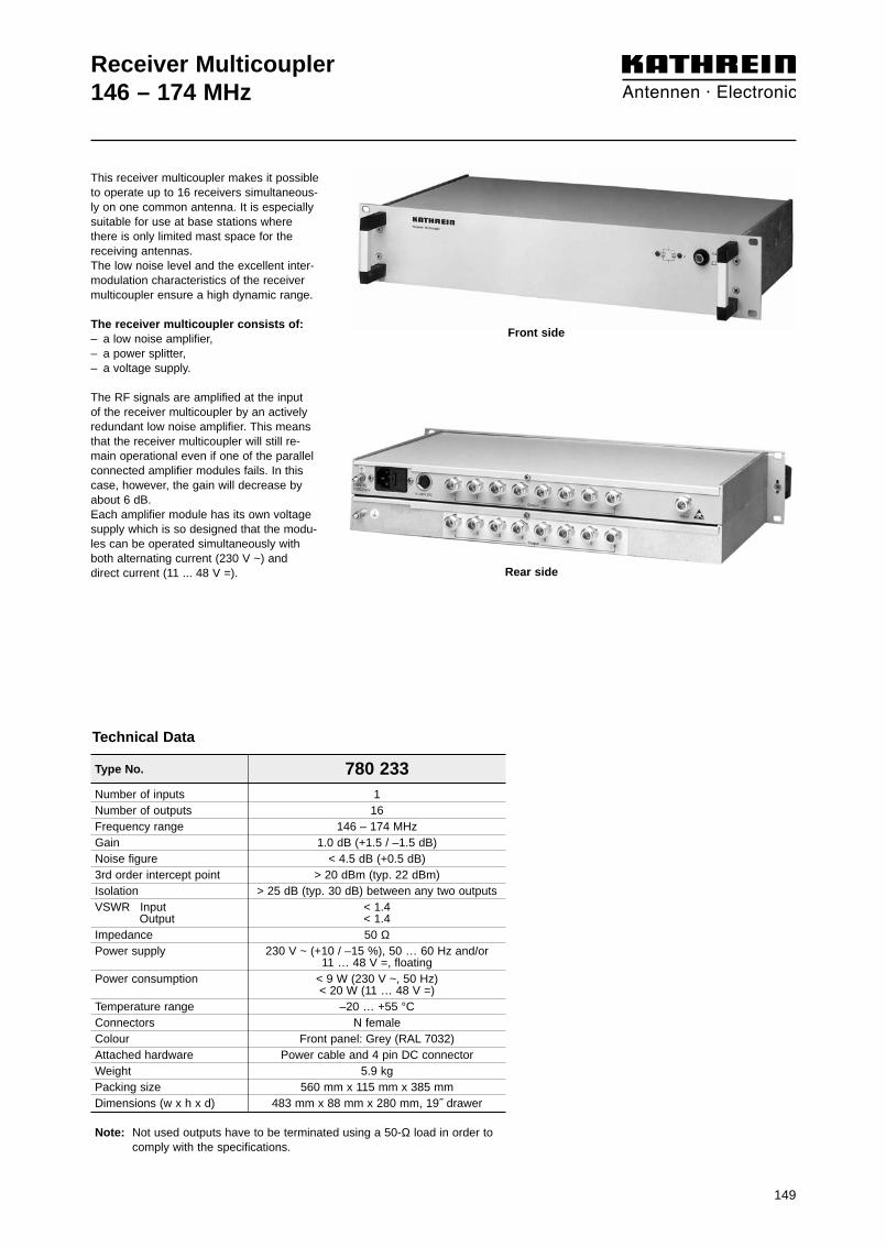
149
Receiver Multicoupler 146 – 174 MHz
Type No. 780 233Number of inputs 1Number of outputs 16Frequency range 146 – 174 MHzGain 1.0 dB (+1.5 / –1.5 dB)Noise figure < 4.5 dB (+0.5 dB)3rd order intercept point > 20 dBm (typ. 22 dBm)Isolation > 25 dB (typ. 30 dB) between any two outputs VSWR Input < 1.4VSWR Output < 1.4Impedance 50 ΩPower supply 230 V ~ (+10 / –15 %), 50 … 60 Hz and/or
11 … 48 V =, floatingPower consumption < 9 W (230 V ~, 50 Hz)
< 20 W (11 … 48 V =)Temperature range –20 … +55 °CConnectors N femaleColour Front panel: Grey (RAL 7032)Attached hardware Power cable and 4 pin DC connectorWeight 5.9 kgPacking size 560 mm x 115 mm x 385 mmDimensions (w x h x d) 483 mm x 88 mm x 280 mm, 19˝ drawer
Note: Not used outputs have to be terminated using a 50-Ω load in order to comply with the specifications.
Technical Data
This receiver multicoupler makes it possibleto operate up to 16 receivers simultaneous-ly on one common antenna. It is especiallysuitable for use at base stations wherethere is only limited mast space for the receiving antennas.The low noise level and the excellent inter-modulation characteristics of the receivermulticoupler ensure a high dynamic range.
The receiver multicoupler consists of:– a low noise amplifier,– a power splitter,– a voltage supply.
The RF signals are amplified at the input of the receiver multicoupler by an actively redundant low noise amplifier. This meansthat the receiver multicoupler will still re-main operational even if one of the parallelconnected amplifier modules fails. In thiscase, however, the gain will decrease byabout 6 dB.Each amplifier module has its own voltagesupply which is so designed that the modu-les can be operated simultaneously withboth alternating current (230 V ~) anddirect current (11 ... 48 V =).
Front side
Rear side

150
Type No. 727 621
Receiver Multicoupler 380 – 470 MHz
Number of inputs 1Number of outputs 8Frequency range 380 – 470 MHz
Special tuning is possiblein the range of 350 to 550 MHz
Gain 3 dB +1.5 / –1.5 dBNoise figure < 3.5 dB +0.5 / –1 dB3rd order intercept point > 16 dBm (typ. 19 dBm)Isolation > 25 dB (typ. 30 dB) between any two outputsVSWR
Input < 1.4Output < 1.4
Impedance 50 ΩPower Supply 230 V +10 / –15 %, 50 … 60 Hz and/or
+11 … +48 V DC, minus groundedPower Consumption < 9 W (230 V, 50 Hz)
< 20 W (+11 … +48 V DC)Temperature range –20 … +50 °CConnectors N femaleColour Front panel: Grey (RAL 7032)Attached hardware Power cable and 4 pin DC connectorWeight 4.0 kgPacking size 560 mm x 105 mm x 385 mmDimensions (w x h x d) 483 mm x 44 mm x 280 mm, 19˝ drawer
Note: Not used outputs have to be terminated using a 50-Ω load in order to comply with the specifications.
Technical Data
This receiver multicoupler makes it possible to operate up to 8 receivers simultaneously on onecommon antenna. It is especially suitable for use at base stations where there is only limited mastspace for the receiving antennas.The low noise level and the excellent intermodula-tion characteristics of the receiver multicouplerensure a high dynamic range.
The receiver multicoupler consists of:– a low-noise amplifier,– a power splitter,– a voltage supply.
The HF signals are amplified at the input of the receiver multicoupler by an actively redundant low-noise amplifier. This means that the receiver multi-coupler will still remain operational even if one ofthe parallel connected amplifier modules fails. Inthis case, however, the amplification will decreaseby about 6 dB.
Each amplifier module has its own voltage supplywhich is so designed that the modules can be ope-rated simultaneously with both alternating current(230 V) and direct current ( +11 ... +48 DC).
Front side
Rear side

Number of Inputs 1Number of Outputs 16Frequency range 380 – 470 MHz
Special tuning is possiblein the range of 350 to 550 MHz
Gain 1 dB +1.5 / –1.5 dBNoise figure < 4.3 dB +0.5 / –1 dB3rd order intercept point > 12 dBm (typ. 16 dBm)Isolation > 25 dB (typ. 30 dB) between any two outputsVSWR
Input < 1.4Output < 1.4
Impedance 50 ΩPower Supply 230 V +10 / –15 %, 50 … 60 Hz and/or
+11 … +48 V DC, minus groundedPower Consumption < 9 W (230 V, 50 Hz)
< 20 W (+11 … +48 V DC)Temperature range –20 … +55 °CConnectors N femaleColour Front panel: Grey (RAL 7032)Attached hardware Power cable and 4 pin DC connectorWeight 5.9 kgPacking size 560 mm x 115 mm x 435 mmDimensions (w x h x d) 483 mm x 88 mm x 280 mm, 19˝ drawer
Note: Not used outputs have to be terminated using a 50-Ω load in order to comply with the specifications.
151
Receiver Multicoupler 380 – 470 MHz
Type No. 727 622
Technical Data
This receiver multicoupler makes it possible to operate up to 16 receivers simultaneously on onecommon antenna. It is especially suitable for use at base stations where there is only limited mastspace for the receiving antennas.The low noise level and the excellent intermodula-tion characteristics of the receiver multicoupler ensure a high dynamic range.
The receiver multicoupler consists of:– a low-noise amplifier,– a power splitter,– a voltage supply.
The HF signals are amplified at the input of the receiver multicoupler by an actively redundant low-noise amplifier. This means that the receivermulticoupler will still remain operational even if oneof the parallel connected amplifier modules fails. In this case, however, the amplification will de-crease by about 6 dB.
Each amplifier module has its own voltage supplywhich is so designed that the modules can be ope-rated simultaneously with both alternating current(230 V) and direct current ( +11 ... +48 DC).
Front side
Rear side
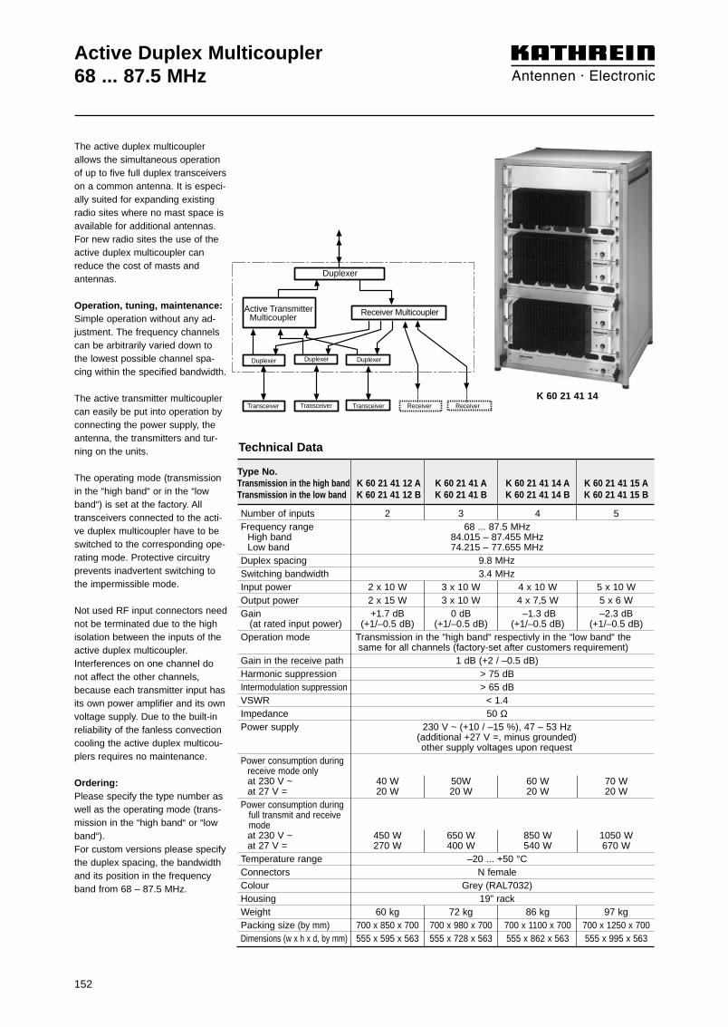
152
Active Duplex Multicoupler68 ... 87.5 MHz
Duplexer
Receiver Multicoupler
Duplexer Duplexer Duplexer
Transceiver Transceiver Transceiver Receiver Receiver
Active TransmitterMulticoupler
The active duplex multicouplerallows the simultaneous operationof up to five full duplex transceiverson a common antenna. It is especi-ally suited for expanding existingradio sites where no mast space isavailable for additional antennas.For new radio sites the use of theactive duplex multicoupler canreduce the cost of masts andantennas.
Operation, tuning, maintenance:Simple operation without any ad-justment. The frequency channelscan be arbitrarily varied down tothe lowest possible channel spa-cing within the specified bandwidth.
The active transmitter multicouplercan easily be put into operation byconnecting the power supply, theantenna, the transmitters and tur-ning on the units.
The operating mode (transmissionin the “high band“ or in the “lowband“) is set at the factory. Alltransceivers connected to the acti-ve duplex multicoupler have to beswitched to the corresponding ope-rating mode. Protective circuitryprevents inadvertent switching tothe impermissible mode.
Not used RF input connectors neednot be terminated due to the highisolation between the inputs of theactive duplex multicoupler.Interferences on one channel donot affect the other channels,because each transmitter input hasits own power amplifier and its ownvoltage supply. Due to the built-inreliability of the fanless convectioncooling the active duplex multicou-plers requires no maintenance.
Ordering:Please specify the type number aswell as the operating mode (trans-mission in the “high band“ or “lowband“). For custom versions please specifythe duplex spacing, the bandwidthand its position in the frequencyband from 68 – 87.5 MHz.
Type No.Transmission in the high band K 60 21 41 12 A K 60 21 41 A K 60 21 41 14 A K 60 21 41 15 ATransmission in the low band K 60 21 41 12 B K 60 21 41 B K 60 21 41 14 B K 60 21 41 15 B
Number of inputs 2 3 4 5Frequency range 68 ... 87.5 MHz
High band 84.015 – 87.455 MHzLow band 74.215 – 77.655 MHz
Duplex spacing 9.8 MHzSwitching bandwidth 3.4 MHzInput power 2 x 10 W 3 x 10 W 4 x 10 W 5 x 10 WOutput power 2 x 15 W 3 x 10 W 4 x 7,5 W 5 x 6 WGain +1.7 dB 0 dB –1.3 dB –2.3 dB
(at rated input power) (+1/–0.5 dB) (+1/–0.5 dB) (+1/–0.5 dB) (+1/–0.5 dB)Operation mode Transmission in the “high band“ respectivly in the “low band“ the
same for all channels (factory-set after customers requirement)Gain in the receive path 1 dB (+2 / –0.5 dB)Harmonic suppression > 75 dBIntermodulation suppression > 65 dBVSWR < 1.4Impedance 50 ΩPower supply 230 V ~ (+10 / –15 %), 47 – 53 Hz
(additional +27 V =, minus grounded)other supply voltages upon request
Power consumption during receive mode onlyat 230 V ~ 40 W 50W 60 W 70 Wat 27 V = 20 W 20 W 20 W 20 W
Power consumption duringfull transmit and receivemodeat 230 V ~ 450 W 650 W 850 W 1050 Wat 27 V = 270 W 400 W 540 W 670 W
Temperature range –20 ... +50 °CConnectors N femaleColour Grey (RAL7032)Housing 19” rackWeight 60 kg 72 kg 86 kg 97 kgPacking size (by mm) 700 x 850 x 700 700 x 980 x 700 700 x 1100 x 700 700 x 1250 x 700Dimensions (w x h x d, by mm) 555 x 595 x 563 555 x 728 x 563 555 x 862 x 563 555 x 995 x 563
Technical Data
K 60 21 41 14

153
Active Duplex Multicoupler146 ... 174 MHz
Duplexer
Receiver Multicoupler
Duplexer Duplexer Duplexer
Transceiver Transceiver Transceiver Receiver Receiver
Active TransmitterMulticoupler
The active duplex multicouplerallows the simultaneous operationof up to five full duplex transceiverson a common antenna. It is especi-ally suited for expanding existingradio sites where no mast space isavailable for additional antennas.For new radio sites the use of theactive duplex multicoupler canreduce the cost of masts andantennas.
Operation, tuning, maintenance:Simple operation without any ad-justment. The frequency channelscan be arbitrarily varied down tothe lowest possible channel spa-cing within the specified bandwidth.
The active transmitter multicouplercan easily be put into operation byconnecting the power supply, theantenna, the transmitters and tur-ning on the units.
The operating mode (transmissionin the “high band“ or in the “lowband“) is set at the factory. Alltransceivers connected to the acti-ve duplex multicoupler have to beswitched to the corresponding ope-rating mode. Protective circuitryprevents inadvertent switching tothe impermissible mode.Not used RF input connectors neednot be terminated due to the highisolation between the inputs of theactive duplex multicoupler.Interferences on one channel donot affect the other channels,because each transmitter input hasits own power amplifier and its ownvoltage supply. Due to the built-inreliability of the fanless convectioncooling the active duplex multicou-plers requires no maintenance.
Ordering:Please specify the type number aswell as the operating mode (trans-mission in the “high band“ or “lowband“). For custom versions please specifythe duplex spacing, the bandwidthand its position in the frequencyband from 146 – 174 MHz.
Type No.Transmission in the high band K 60 21 21 12 A K 60 21 21 A K 60 21 21 14 A K 60 21 21 15 ATransmission in the low band K 60 21 21 12 B K 60 21 21 B K 60 21 21 14 B K 60 21 21 15 B
Number of inputs 2 3 4 5Frequency range 146 ... 174 MHz
High band 172.14 – 174.12 MHzLow band 167.54 – 169.52 MHz
Duplex spacing 4.6 MHzSwitching bandwidth 2.0 MHzInput power 2 x 10 W 3 x 10 W 4 x 10 W 5 x 10 WOutput power 2 x 15 W 3 x 10 W 4 x 7.5 W 5 x 6 WGain +1.7 dB 0 dB -1.3 dB -2.3 dB
(at rated input power) (+1/–0.5 dB) (+1/–0.5 dB) (+1/–0.5 dB) (+1/–0.5 dB)Operation mode Transmission in the “high band“ respectivly in the “low band“ the
same for all channels (factory-set after customers requirement)Gain in the receive path 1 dB (+2 / –0.5 dB)Harmonic suppression > 75 dBIntermodulation suppression > 65 dBVSWR < 1.4Impedance 50 ΩPower supply 230 V ~ (+10 / –15 %), 47 – 53 Hz
(additional +27 V =, minus grounded)other supply voltages upon request
Power consumption during receive mode onlyat 230 V ~ 40 W 50W 60 W 70 Wat 27 V = 20 W 20 W 20 W 20 W
Power consumption during full transmit and receive modeat 230 V ~ 450 W 650 W 850 W 1050 Wat 27 V = 270 W 400 W 540 W 670 W
Temperature range –20 ... +50 °CConnectors N femaleColour Grey (RAL7032)Housing 19” rackWeight 60 kg 72 kg 86 kg 97 kgPacking size (by mm) 700 x 850 x 700 700 x 980 x 700 700 x 1100 x 700 700 x 1250 x 700Dimensions (w x h x d, by mm) 555 x 595 x 563 555 x 728 x 563 555 x 862 x 563 555 x 995 x 563
Technical Data
K 60 21 21 14

154

155
Combiner Systems
Co
mb
iner
Sys
tem
s

156
Combiner Systems
Besides our standard versions we also manufacturemany custom versions and combiner systems, whichwe adapt to your requirements or special operatingconditions.
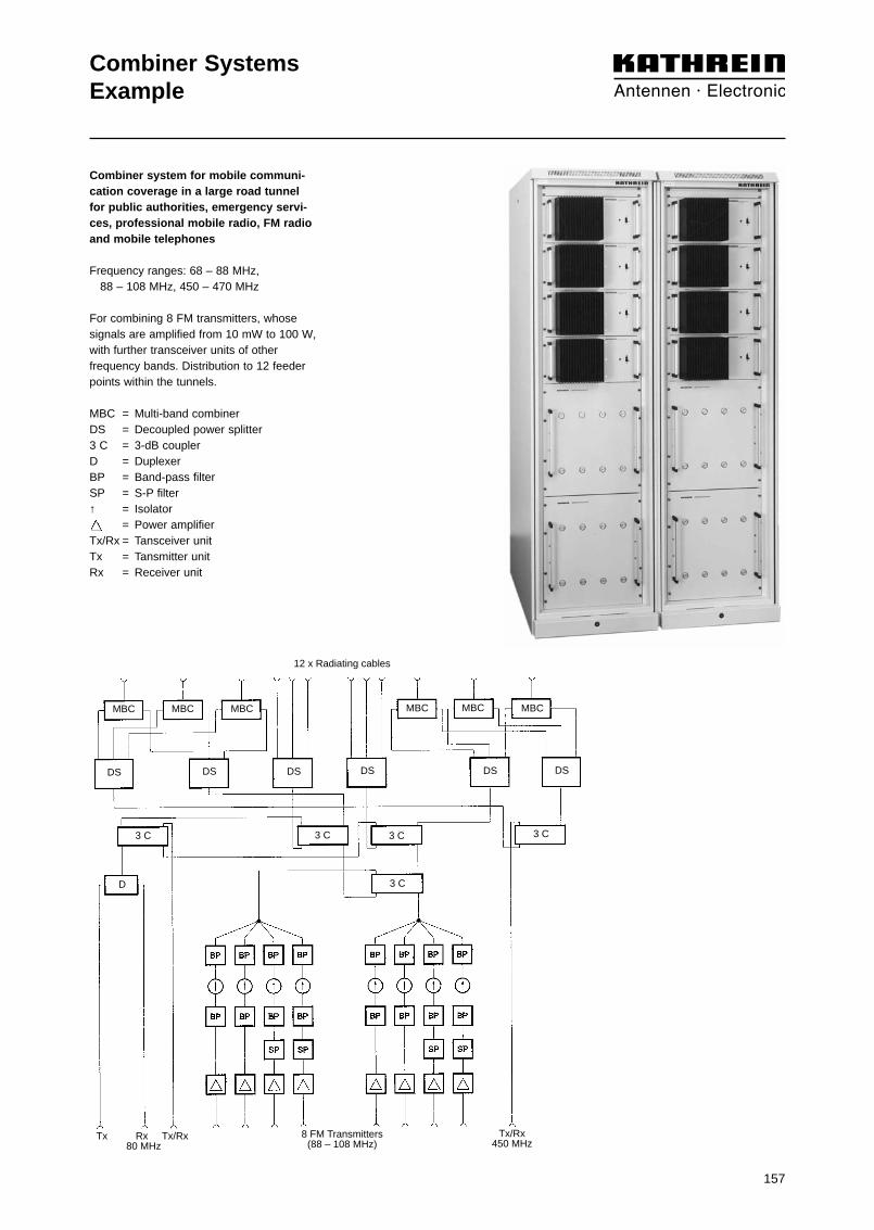
157
Combiner SystemsExample
Combiner system for mobile communi-cation coverage in a large road tunnelfor public authorities, emergency servi-ces, professional mobile radio, FM radioand mobile telephones
Frequency ranges: 68 – 88 MHz, 88 – 108 MHz, 450 – 470 MHz
For combining 8 FM transmitters, whosesignals are amplified from 10 mW to 100 W,with further transceiver units of otherfrequency bands. Distribution to 12 feederpoints within the tunnels.
MBC = Multi-band combinerDS = Decoupled power splitter3 C = 3-dB couplerD = DuplexerBP = Band-pass filterSP = S-P filter↑ = Isolator
= Power amplifierTx/Rx = Tansceiver unitTx = Tansmitter unitRx = Receiver unit
12 x Radiating cables
MBCMBC MBC MBC MBC MBC
DSDSDS DS DSDS
3 C3 C
3 C
3 C3 C
D
T R 8 FM Transmitters(88 – 108 MHz)
Tx/Rx450 MHz
Tx Rx Tx/Rx 80 MHz
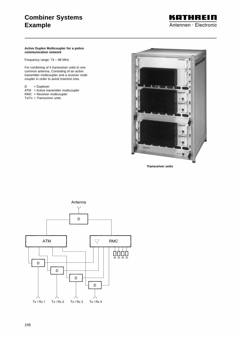
158
Combiner SystemsExample
Active Duplex Multicoupler for a police communication network
Frequency range: 74 – 88 MHz
For combining of 4 transceiver units to onecommon antenna. Consisting of an activetransmitter multicoupler and a receiver multi-coupler in order to aviod insertion loss.
D = DuplexerATM = Active transmitter multicouplerRMC = Receiver multicouplerTx/Tx = Transceiver units
Transceiver units

159
Combiner SystemsExample
Combiner network for mobile communi-cation coverage in tunnels for publicauthorities, emergency services, FM ra-dio, paging systems and mobile telepho-nes
Frequency ranges: 75 – 85 MHz, 88 – 108 MHz, 170 MHz, 380 – 470 MHz, 870 – 960 MHz
For combining several transmitters and / orreceivers of different frequency bands ontoone radiating cable each.
MBC = Multiband combiner3 C = 3-dB couplerRJ = Hybrid ring junctionDS = Decoupled power splitterRMC = Receiver multicoupler
Radiating cable 1 Radiating cable 2
MBC
MBC
MBC
RJ
3 C
FMTransmitters
DS DS
Receivers
RMC RMC RMC
MBC
MBC

160
Combiner SystemsExample
Combiner system for mobile communica-tion coverage in tunnels for publicauthorities, emergency services and railwayservices, e. g. for suburban railways
Frequency range: 80 MHz, 150 MHz, 450 MHz
For combining several transceiver units (sim-plex and duplex) of different frequency bandsand splitting to six radiating cables and additio-nally two antennas (at 80 MHz), includingremote-control monitoring.
MBC = Multiband combinerMU = Measurement unitD = DuplexerDS = Decoupled splitterRJ = Hybrid ring junction10 C = 10-dB coupler
= Receiver amplifier= Power amplifier
6 x Radiating cables
MBCMBCMBCMBCMBCMBC
MU MU
DU
DPSDPS DPS DPS DPS DPS DPS DPS
RJ RJ RJ
RJ
10 CD
10 C
D
Antenna 1/2
D
DD
2 Transceiver units(simplex)
Transceiver unit(duplex)
Transceiver unit(duplex)
RJ
Radiating cable
D
DS DS DS DS DS DS DSDS

161
Combiner SystemsExample
Antenna
D D
Tx/Rx 1 Tx/Rx 2 Tx/Rx 3 Tx/Rx 4
Combiner system for a mobile communi-cation network for motor-racing vehicles
Frequency range: 146 – 174 MHz
For combining 4 simplex transceivers withvariable frequencies onto one commonantenna.
D = DuplexerSP = S-P filterTx/Rx = Transceiver unit

162
Combiner SystemsExample
Radiating Radiating cable 1 cable 2
3 C
D
Rx 6(duplex)
Tx/Rx 4(duplex)
Tx 6(duplex)
Tx/Rx 3Tx/Rx 2Tx/Rx 1 Rx 5(duplex)
Tx 5(duplex)
Combiner system for the mobile commu-nication network of a public transportcompany (e. g. underground railway) forprofessional mobile radio, public authori-ties and emergency services
Frequency range: 148 – 173 MHz
For combining several transceiver units (simplex and duplex) with minimal frequencyspacing and splitting to two radiating cables.
3 C = 3-dB couplerD = DuplexerBP = Band-pass filterSP = S-P filter↑ = IsolatorTx/Rx = Transceiver unitTx = Transmitter unitRx = Receiver unit

163
Combiner SystemsExample
Radiating cable 1 Radiating cable 2 Radiating cable 3 Radiating cable 4 Radiating cable 5
MBC MBCMBC MBC MBC
3 C
3 C
3 C
3 C
10 C
DS
Tx/Rx 2 Tx/Rx 3 Tx/Rx 4 Rx 5(duplex)
Rx 6(duplex)
Tx 5(duplex)
Tx 6(duplex)
Tx/Rx 1458 MHz
Combiner system for coverage in a tunnel
Frequency ranges: 148 – 173 MHzand 458 MHz
For combining several transmitters and/orreceivers (duplex/simplex) with minimal fre-quency spacing and splitting to five radiatingcables.
MBC = Multiband combiner3 C = 3-dB coupler10 C = 10-dB couplerDS = Decoupled splitterBP = Band-pass filterTx/Rx = Transceiver unitTx = Transmitter unitRx = Receiver unit

164
Combiner SystemsExample
Antenna
RMC ATM
Tx/Rx 1 Tx/Rx 2 Receiver(duplex)
Transmitter(duplex)
Active combiner system for a commondata and voice communication network
Frequency range: 148 – 156 MHz
For combining several duplex and simplexchannels to one common antenna.
The duplex channels are combined on thetransmitting side via an active transmittermulticoupler and on the receiving side via a receiver multicoupler, in order to reduceinsertion loss.
BP = Band-pass filterSP = S-P filterRMC = Receiver multicouplerATM = Active transmitter multicouplerTx/Rx = Transceiver unit

165
Combiner SystemsExample
Combiner system for a mobile communi-cation network of a public transport com-pany
Frequency range: 148 – 165 MHz
For combining several transceivers (simplexand duplex) with minimal frequency spacingonto two base-station antennas.
BP = Band-pass filterSP = S-P filterD = Duplexer↑ = IsolatorTx/Rx = Transceiver unit
Antenna 1 Antenna 2
D
D D
Tx/Rx 5(duplex)
Tx/Rx 6(duplex)
Tx/Rx 2(duplex)
Tx/Rx 3 Tx/Rx 4Tx/Rx 1
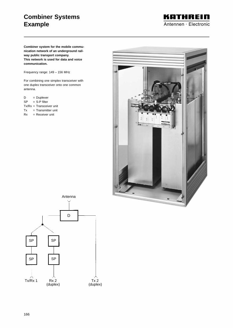
166
Combiner SystemsExample
Antenna
D
SP SP
SP SP
Tx/Rx 1 Rx 2 Tx 2 (duplex) (duplex)
Combiner system for the mobile commu-nication network of an underground rail-way public transport company. This network is used for data and voicecommunication.
Frequency range: 149 – 156 MHz
For combining one simplex transceiver withone duplex transceiver onto one commonantenna.
D = DuplexerSP = S-P filterTx/Rx = Transceiver unitTx = Transmitter unitRx = Receiver unit

167
Combiner SystemsExample
Combiner system for the synchronizedradio network of a public transport com-pany
Frequency range: 149 – 156 MHz
For combining of several transceiving units(simplex and duplex) with minimal frequencyspacing onto one base station antenna.
BP = Band-pass filterSP = S-P filterTx/Rx = Transceiver unitTx = Transmitter unitRx = Receiver unit
Antenna
Tx/Rx 1 Rx 2 Tx/Rx 3 (duplex)
Tx/Rx 4 Tx 2 (duplex)

168
Combiner SystemsExample
Combiner system for a mobile communi-cation network of a public transport com-pany for data and voice communication
Frequency range: 149 – 156 MHz
For combining several transceiver units(simplex and duplex) with minimal frequencyspacing onto one base-station antenna.
BP = Band-pass filterSP = S-P filterRJ = Hybrid ring junction↑ = IsolatorTx/Rx = Transceiver unitTx = Transmitter unitRx = Receiver unit
Antenna
RJ RJ
Tx/Rx 1 Tx/Rx 4Tx 2 Tx 3 Rx 2 Rx 3

169
Combiner SystemsExample
Combiner system for mobile communi-cation coverage in a railway station forprofessional mobile radio, public autho-rities and emergency services
Frequency range: 151 – 174 MHz
For combining several transceivers (duplexand simplex) with minimal frequency spa-cing and distributing them onto 4 antennas.
3 C = 3-dB couplerD = DuplexerBP = Band-pass filterSP = S-P filterTx/Rx = Transceiver unitTx = Transmitter unitRx = Receiver unit
Antenna 1 Antenna 2 Antenna 3 Antenna 4
3 C
3 C
3 C
3 C
Tx/Rx 1 Tx/Rx 2 Tx/Rx 3 Tx/Rx 4 Tx 5 Rx 5
D

170
Combiner SystemsExample
Combiner system for a mobile communi-cation network for security services
Frequency range: 158 – 169 MHz
For combining several duplex transceivingunits, whereby one frequency pair is opera-ted in exchanged band position.
BP = Band-pass filterRJ = Hybrid ring junctionRMC = Receiver multicoupler↑ = Isolator
RJ
RJRJ
Receivers Transmitters Transmitters
RJ
RJ RJ
Transmitting antenna 1 Transmitting antenna 2Receiving antenna
RMC

171
Combiner SystemsExample
Antenna
Tx 1 Tx 2
Combiner system for an ERMES pagingnetwork and one further paging system
Frequency range: 169 – 173 MHz
For combining two transmitters to one com-mon antenna.
BP = Band-pass filterTx = Transmitter unit

172
Combiner SystemsExample
Combiner system for a police mobile com-munication TETRA network
Frequency range 380 – 385 / 390 – 395 MHz
For combining eight transceivers with TETRAfrequencies onto one common antenna.
3DB = 3-dB couplerBP = Band-pass filterHTC = Hybrid transmitter combiner RMC = Receiver multicouplerDU = DuplexerTx/Rx = Transceiver unit

173
Combiner SystemsExample
Combiner system for a mobile communicationnetwork of a railway station
Frequency range 410 … 420 MHz
For combining of several receiving/transmitting units (simplex) to four antennas.
BP = Band-pass filterSP = S-P filter
Antenna 1 Antenna 2 Antenna 3 Antenna 4
Transmitter / Receiver units(simplex)

174
Combiner SystemsExample
Combiner system for trunking system base stations
Frequency range 410 … 430 MHz
For combining of 8 transmitters and 8 receivers each toone common transmitting/receiving antenna.
DU = DuplexerMU = Measuring unit BP = Band-pass filterRMC = Receiver multicoupler FTC = Filter transmitter combiner ↑ = Isolator
Antenna
ReceiversTransmitters
MU DU
FTC
RMC
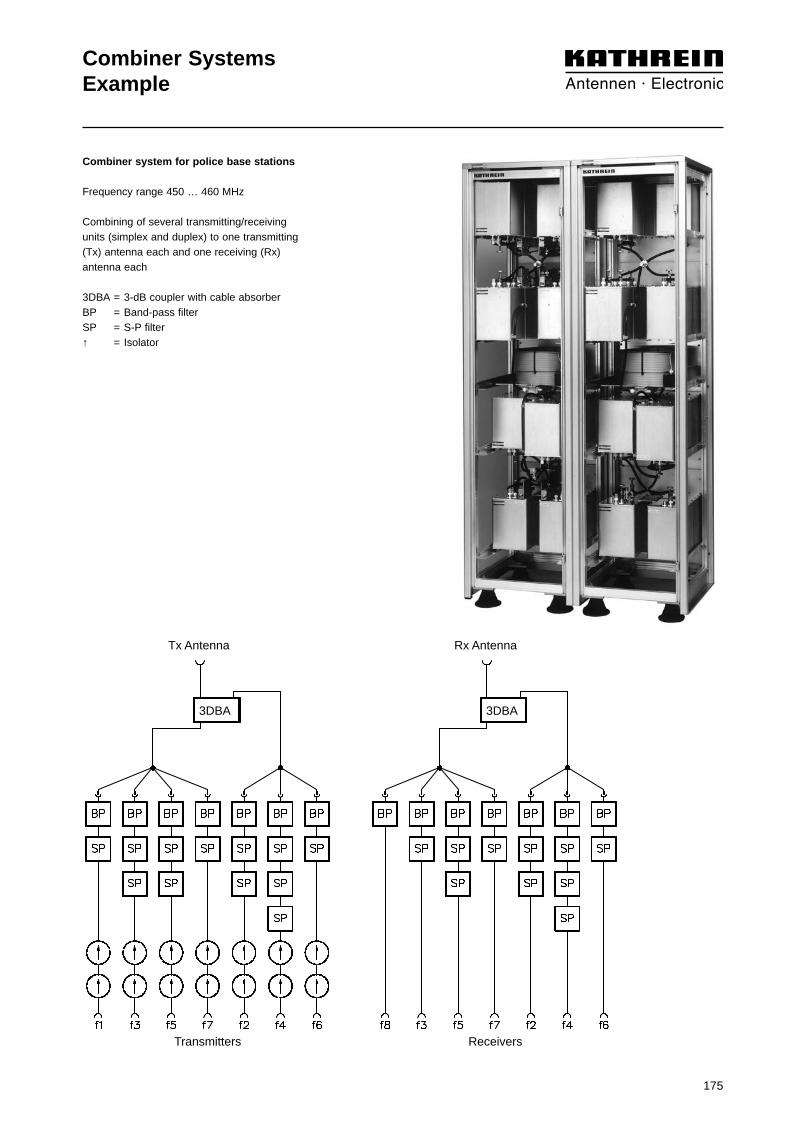
175
Combiner SystemsExample
Combiner system for police base stations
Frequency range 450 … 460 MHz
Combining of several transmitting/receivingunits (simplex and duplex) to one transmitting(Tx) antenna each and one receiving (Rx) antenna each
3DBA = 3-dB coupler with cable absorberBP = Band-pass filterSP = S-P filter↑ = Isolator
Tx Antenna Rx Antenna
Transmitters Receivers
3DBA3DBA

Service radio for governmental and emergency
Frequency range: 450 – 465 MHz
For combining of 4 transmitters and 4 receiverseach to one common Tx/Rx-antenna.
D = DuplexerDS = Decoupled power splitterRMC = Receiver multicoupler↑ = IsolatorTx = TransmitterRx = Receiver
Combiner SystemsExample
176

177
Note

178
Note

179
Note

9987
.212
/090
5/3/
ZW
T/H
AS
ubje
ct t
o al
tera
tion.
Internet: http://www.kathrein.de
KATHREIN-Werke KG . Phone +49 8031 184-0 . Fax +49 8031 184-494Anton-Kathrein-Straße 1 – 3 . P.O. Box 10 04 44 . 83004 Rosenheim . Germany
Antennen . Electronic