kawasaki robot z series · kawasaki robot z series materials and speci˜ cations are subject to...
TRANSCRIPT
....
Large payload robots - up to 300 kgZ seriesKawasaki Robot
Z series
MCat. No. ZS1807✽ Materials and speci� cations are subject to change without notice.
ISO certi� ed in Wixom, Michigan U.S.A.
CAUTIONS TO BE TAKEN TO ENSURE SAFETY
● For those persons involved with the operation / service of your system, including Kawasaki Robot, they must strictly observe all safety regulations at all times. They should carefully read the Manuals and other related safety documents.
● Products described in this catalogue are general industrial robots. Therefore, if a customer wishes to use the Robot for special purposes, which might endanger operators or if the Robot has any problems, please contact us. We will be pleased to help you.
● Be careful as Photographs illustrated in this catalogue are frequently taken after removing safety fences and other safety devices stipulated in the safety regulations from the Robot operation system.
Kawasaki RobotKawasaki Robotics (USA), Inc.Corporate Headquarters for Americas28140 Lakeview Drive, Wixom, MI 48393, U.S.A.Phone: +1-248-446-4100 Fax: +1-248-446-4200
Global Network
Kawasaki Heavy Industries, Ltd.Tokyo Head Of� ce/Robot Division1-14-5, Kaigan, Minato-ku, Tokyo 105-8315, JapanPhone: +81-3-3435-6852 Fax: +81-3-3437-9880
Kawasaki Heavy Industries, Ltd.Akashi Works/Robot Division1-1, Kawasaki-cho, Akashi, Hyogo 673-8666, JapanPhone: +81-78-921-2946 Fax: +81-78-923-6548
Kawasaki Robotics (UK), Ltd.Unit 4 Easter Court, Europa Boulevard, Westbrook WarringtonCheshire, WA5 7ZB, United KingdomPhone: +44-1925-71-3000 Fax: +44-1925-71-3001
Kawasaki Robotics GmbHIm Taubental 32, 41468 Neuss, GermanyPhone: +49-2131-3426-0 Fax: +49-2131-3426-22
Kawasaki Robotics Korea, Ltd.43, Namdong-daero 215beon-gil, Namdong-guIncheon, 21633, KoreaPhone: +82-32-821-6941 Fax: +82-32-821-6947
Kawasaki Robotics (Tianjin) Co., Ltd.Bldg 3, No.16, Xiang’an Road, TEDA, Tianjin 300457, ChinaPhone: +86-22-5983-1888 Fax: +86-22-5983-1889
Kawasaki Motors Enterprise (Thailand) Co., Ltd.Rayong Robot Center119/10 Moo 4 T. Pluak Daeng, A. Pluak Daeng, Rayong 21140, Thailand Phone: +66-38-955-040-58 Fax: +66-38-955-145
KawasakiRobotics.com
..
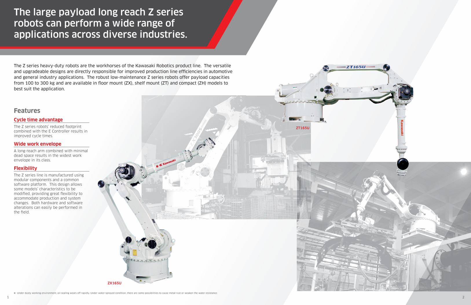
ZT165U
ZX165U
✻ Under dusty working environment, oil-sealing wears off rapidly. Under water-sprayed condition, there are some possibilities to cause metal-rust or weaken the water resistance.
FeaturesCycle time advantageThe Z series robots’ reduced footprint combined with the E Controller results in improved cycle times.
Wide work envelopeA long-reach arm combined with minimal dead space results in the widest work envelope in its class.
FlexibilityThe Z series line is manufactured using modular components and a common software platform. This design allows some models’ characteristics to be modi� ed, providing great � exibility to accommodate production and system changes. Both hardware and software alterations can easily be performed inthe � eld.
The Z series heavy-duty robots are the workhorses of the Kawasaki Robotics product line. The versatile and upgradeable designs are directly responsible for improved production line ef� ciencies in automotive and general industry applications. The robust low-maintenance Z series robots offer payload capacities from 100 to 300 kg and are available in � oor mount (ZX), shelf mount (ZT) and compact (ZH) models to best suit the application.
The large payload long reach Z series robots can perform a wide range of applications across diverse industries.
1 2
....
Standard speci� cations
ZX130U ZX130L ZX165U ZX200S ZX300S ZH100UType Articulated Articulated
Degrees of freedom (axes) 6 (Option: 7) 6 (Option: 7)
Max. payload (kg) 130 130 165 200 300 100
Max. reach (mm) 2,651 2,951 2,651 2,651 2,501 1,634
Positional repeatability (mm) ✽1 ±0.3 ±0.3
WorkenvelopeandMax. speed
Axis Motion range (°) Max. speed (°/s) Motion range (°) Max. speed (°/s) Motion range (°) Max. speed (°/s) Motion range (°) Max. speed (°/s) Motion range (°) Max. speed (°/s) Motion range (°) Max. speed (°/s)
Arm rotation (JT1) ±180 110 ±180 110 ±180 110 ±180 105 ±180 100 ±160 140
Arm out-in (JT2) +75 - –60 110 +75 - –60 110 +75 - –60 110 +75 - –60 110 +75 - –60 85 +120 - –60 100
Arm up-down (JT3) +250 - –120 110 +250 - –120 110 +250 - –120 115 +250 - –120 105 +250 - –120 85 +75 - –90 100
Wrist swivel (JT4) ±360 140 ±360 140 ±360 140 ±360 120 ±360 90 ±360 150
Wrist bend (JT5) ±130 135 ±130 135 ±130 155 ±120 120 ±120 90 ±130 150
Wrist twist (JT6) ±360 230 ±360 230 ±360 260 ±360 200 ±360 150 ±360 250
Arm traverse (JT7) ✽2 standard 2,000 mm 1,000 mm/s standard 2,000 mm 1,000 mm/s standard 2,000 mm 1,000 mm/s standard 2,000 mm 1,000 mm/s standard 2,000 mm 1,000 mm/s standard 2,000 mm 1,000 mm/s
Moment(N·m) ✽3
Wrist swivel (JT4) 735 735 911.4 1,274 1,715 874
Wrist bend (JT5) 735 735 911.4 1,274 1,715 874
Wrist twist (JT6) 421.4 421.4 450.8 686 862 392
Moment of inertia(kg·m2) ✽3
Wrist swivel (JT4) 107.8 51.9 78.4 117.6 166.6 90.0
Wrist bend (JT5) 107.8 51.9 78.4 117.6 166.6 90.0
Wrist twist (JT6) 45.9 27.4 40.2 63.7 107.8 20.0
Mass (kg) 1,350 1,400 1,350 1,400 1,400 750
Mounting Floor Floor
Integrated function Air piping (12 mm dia. x 2) Air piping (12 mm dia. x 2) —
OptionMechanical hard stop JT1/JT2/JT3, End stroke limit switch JT1/JT2/JT3, Special color, Traversing track,
Internal wiring for end effector, Double solenoid valve 1/2, Single solenoid valve 1/2, Double sol.1+single sol.1, FRL unit, Internal hoses of cooling water for welding gun, Wiring for solenoid valve for grippers (DC24V)
Mechanical hard stop JT1/JT2/JT3, End stroke limit switch JT1/JT2/JT3, Special color, Traversing track, Internal wiring for end effector, Double solenoid valve 1/2, Single solenoid valve 1/2, Double
sol.1+single sol.1, FRL unit, Internal hoses of cooling water for welding gun, Wiring for solenoid valve for grippers (DC24V)
Mechanical hard stop JT1/JT2/JT3, End stroke limit switch JT1/JT2/JT3,
Special color, Traversing track, Internal wiring for end effector,
Internal hoses of cooling water for welding gun, Wiring for solenoid valve for grippers (DC24V)
Color Munsell 10GY9/1 equivalent Munsell 10GY9/1 equivalent
Power requirements (kVA) ✽4 7.5 7.5
ControllerAmerica & Europe
E02 E02Japan & Asia
✽1: Conforms to ISO9283 ✽2: Option ✽3: In case of using the face plate which is supported by proper bolts and pins ✽4: Depends on the payload and motion patterns
ZT130U ZT165U ZT200SType Articulated
Degrees of freedom (axes) 6 (Option: 7)
Max. payload (kg) 130 165 200
Max. reach (mm) 3,230
Positional repeatability (mm) ✽1 ±0.3
WorkenvelopeandMax. speed
Axis Motion range (°) Max. speed (°/s) Motion range (°) Max. speed (°/s) Motion range (°) Max. speed (°/s)
Arm rotation (JT1) ±180 105 ±180 105 ±180 100
Arm out-in (JT2) +60 - –75 105 +60 - –75 105 +60 - –75 100
Arm up-down (JT3) +165 - –95 105 +165 - –95 105 +165 - –95 90
Wrist swivel (JT4) ±360 140 ±360 135 ±360 120
Wrist bend (JT5) ±130 135 ±130 135 ±120 115
Wrist twist (JT6) ±360 230 ±360 210 ±360 180
Arm traverse (JT7) ✽2 standard 2,000 mm 1,000 mm/s standard 2,000 mm 1,000 mm/s standard 2,000 mm 1,000 mm/s
Moment(N·m) ✽3
Wrist swivel (JT4) 735 911.4 1,274
Wrist bend (JT5) 735 911.4 1,274
Wrist twist (JT6) 421 450.8 686
Moment of inertia(kg·m2) ✽3
Wrist swivel (JT4) 107.8 78.4 117.6
Wrist bend (JT5) 107.8 78.4 117.6
Wrist twist (JT6) 45.9 40.2 63.7
Mass (kg) 1,550 1,550 1,600
Mounting Shelf
Integrated function Air piping (12 mm dia. x 2)
OptionMechanical hard stop JT1/JT2/JT3, End stroke limit switch JT1/JT2/JT3, Special color, Traversing track,
Internal wiring for end effector, Double solenoid valve 1/2, Single solenoid valve 1/2, Double sol.1+single sol.1, FRL unit, Internal hoses of cooling water for welding gun, Wiring for solenoid valve for grippers (DC24V)
Color Munsell 10GY9/1 equivalent
Power requirements (kVA) ✽4 7.5
ControllerAmerica & Europe
E02Japan & Asia
✽1: Conforms to ISO9283 ✽2: Option ✽3: In case of using the face plate which is supported by proper bolts and pins ✽4: Depends on the payload and motion patterns
3 4
....
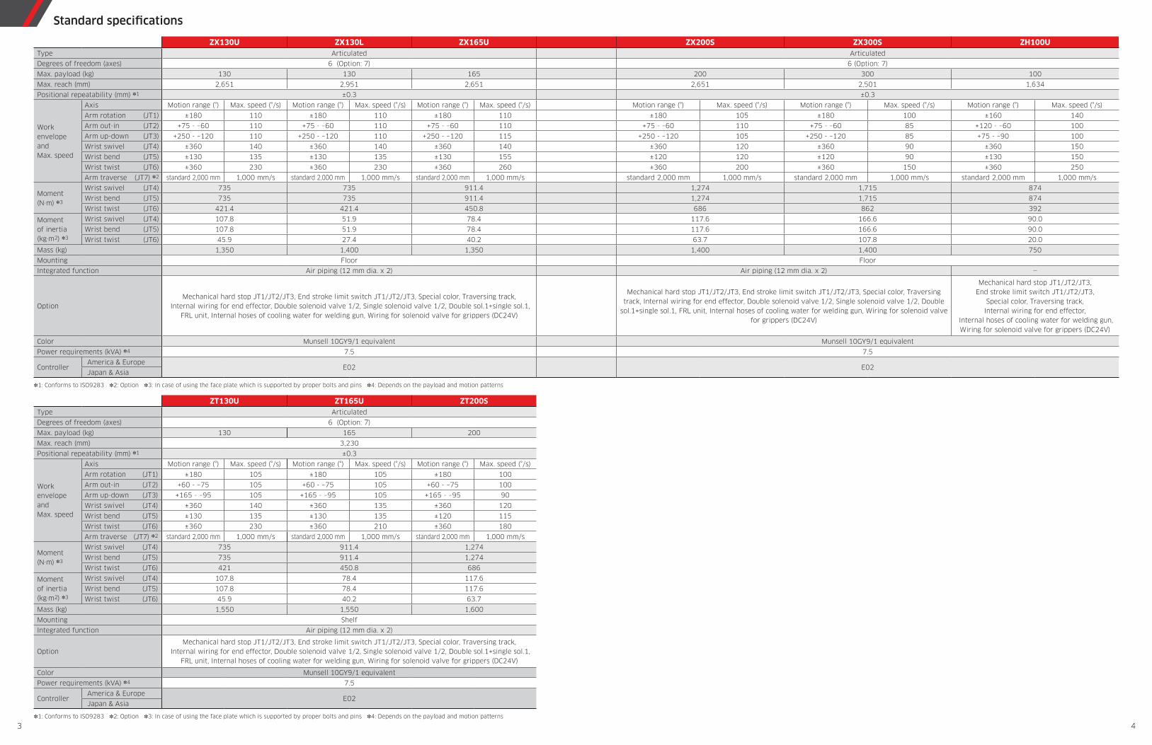
(mm)(mm)
(mm)(mm)
ZH100UZX130L
ZX300SZX130U / ZX165U / ZX200S
X
X
Y
2,5
78
.8
160°
160°
500
1,5
50
90°
60°
120°
75°
1,9
64
.46
14
.4
1,062.4 572
1,634.4
379
800 200
30
05
80
53
0
P
P
JT3
JT3
JT2
JT2
JT1
JT1
JT4±360°JT6±360°
JT5±130°
VIEW A
6−M16Dp30
16070 160
70
70
700
2-
29
0
30
50
0
250 450
205
32
0
41
0
Installation dimensions
ø0.05
2-ø22H9ø22
ø22
205
410
30°
30°
30°
60°
6-M10 Dp12
ø80H7 X Yø0.15
6-M10 Dp16
X Yø0.15
Xø0.04
Xø0.04
ø125
ø92
Dp8
ø55H7
Dp12
ø160
ø160
2-ø10H7
2-ø9H7
Y
A
Dimension: 228
• Conventional type (ø92)
• ISO 9409-1 series 2 (ø125)
Working rangebased on point P
125125500
770
100 100
75
37
0
77
0
12
512
5
30
Installation dimensions
8-ø22
ø0.052-ø25G8
300
300
300
100
100
50
0
JT4±360°
JT5 ±130°
JT6±360°13
150 510 695
1,600
180°
JT1
180°JT1
R517
Interference radius aroundthe rotational axis
Rear side interference area
R1,289 Link H
14
2
90
10 x 2–M6–12/185 x 2–M10–20/25
Dimension: 228
Y
+0.015 02–ø10H7 Dp12
Xø0.04
ø160
30°30°
+0.030 0ø80H7
XDp8
6–M10 Dp12
X Yø0.15
• ISO 9409-1 Series 2 (ø125)Unnecessaryfor standard spec.
ø125
Y30°
60 °
Dimension: 244Xø0.04
ø160
• Conventional type (ø92)+0.030 0ø55H7
XDp12
6–M10 Dp16
X Yø0.15
ø92
VIEW A
27
01,
10
06
70
210 600.5JT275°
288
JT260°
Link H
1,199
1,4
90
JT3
70°
JT3120°
58
80909
0
1,2
25
2,265 2,951
4,0
153,6
40
+0.015 0ø9H7 Dp122–
P
P
Working rangebased on point P
125125500
770
100 100
75
37
0
77
0
12
512
5
30
Installation dimensions
8-ø22
ø0.052-ø25G8
300
300
300
100
100
50
0
180°JT1
JT4±360°
JT5±120°
JT6±360°13
150 360 395
1,150
180°JT1R517
Interference radius aroundthe rotational axis
Rear side interference area
R1,289 Link H
14
2
90
10 x 2–M6–12/185 x 2–M10–20/25
Dp12X
+0.030 0ø68H7
• Conventional type (ø113)
30°
30 °
VIEW A
Dp17+0.015 02–ø10H7
Xø0.04 Dimension: 248
10–M10 Dp17
X Yø0.15
ø200
Y
ø113
Dp8X
+0.035 0ø100H7
• ISO 9409-1 series 1 (ø160)Unnecessaryfor standard spec.
30 °
30 °
Dp12+0.015 02–ø10H7
Xø0.04 Dimension: 231
6–M10 Dp12
ø0.15Y
ø200
ø160
YX
A
58
8090
90
JT3120°
JT275°
288
JT260°
Link H
1,199
1,4
90
JT3
70°
1,2
25
27
01,
10
06
70
210 600.5
3,1
15
1,815
3,1
90
2,501
P
P
Working rangebased on point P
125125500
770
100 100
75
37
0
77
0
12
512
5
30
Installation dimensions
8-ø22
ø0.052-ø25G8
300
300
300
100
100
50
0
JT4±360°
JT5
JT6±360°13
150 510 395
1,300
180°JT1
180°
JT1
R517
Interference radius aroundthe rotational axis
Rear side interference area
R1,289 Link H
14
2
90
10 x 2–M6–12/18
5 x 2–M10–20/25
YX
2–ø10H7 Dp12
Dimension: 228
Y
+0.015 0
Xø0.04
Y30°
60 °
Dimension: 244
+0.015 0ø9H7 Dp12
Xø0.04
ø160
• Conventional type (ø92) for 130U/165U
+0.030 0ø55H7
XDp12
6–M10 Dp16
X Yø0.15
ø92
Dp8X
+0.035 0ø100H7
• ISO 9409-1 series 1 (ø160) for 200S Unnecessary
for standard spec.
30 °
30 °
Dp12+0.015 02–ø10H7
Xø0.04 Dimension: 231
6–M10 Dp12
ø0.15Y
ø200
ø160
ø160
30°30°
+0.030 0ø80H7
XDp8
6–M10 Dp12
X Yø0.15
• ISO 9409-1 series 2 (ø125) for 130U/165U Unnecessary
for standard spec.
ø125
Dp12X
+0.030 0ø68H7
• Conventional type (ø113) for 200S
30°
30 °
VIEW A
Dp17+0.015 0
Xø0.04 Dimension: 248
10–M10 Dp17
X Yø0.15
ø200
2–ø10H7 Y
ø113
A
A
JT275°
2,6511,965
3,4
15
3,3
40
ZX200S
1,2
25
1,199
1,4
90
288
JT260°
Link H 58
8090
90
JT3
70°
JT3120°
27
01,
10
06
70
210 600.5
±130°
±120°ZX200S
ZX130UZX165U
2–
P
P
P
Working rangebased on point P
45.945.945.9
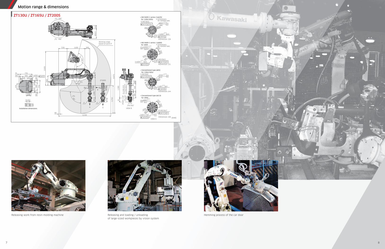
Motion range & dimensions
5 6
..
Releasing and loading / unloadingof large-sized workpieces by vision system
Hemming process of the car doorReleasing work from resin molding machine
(mm)
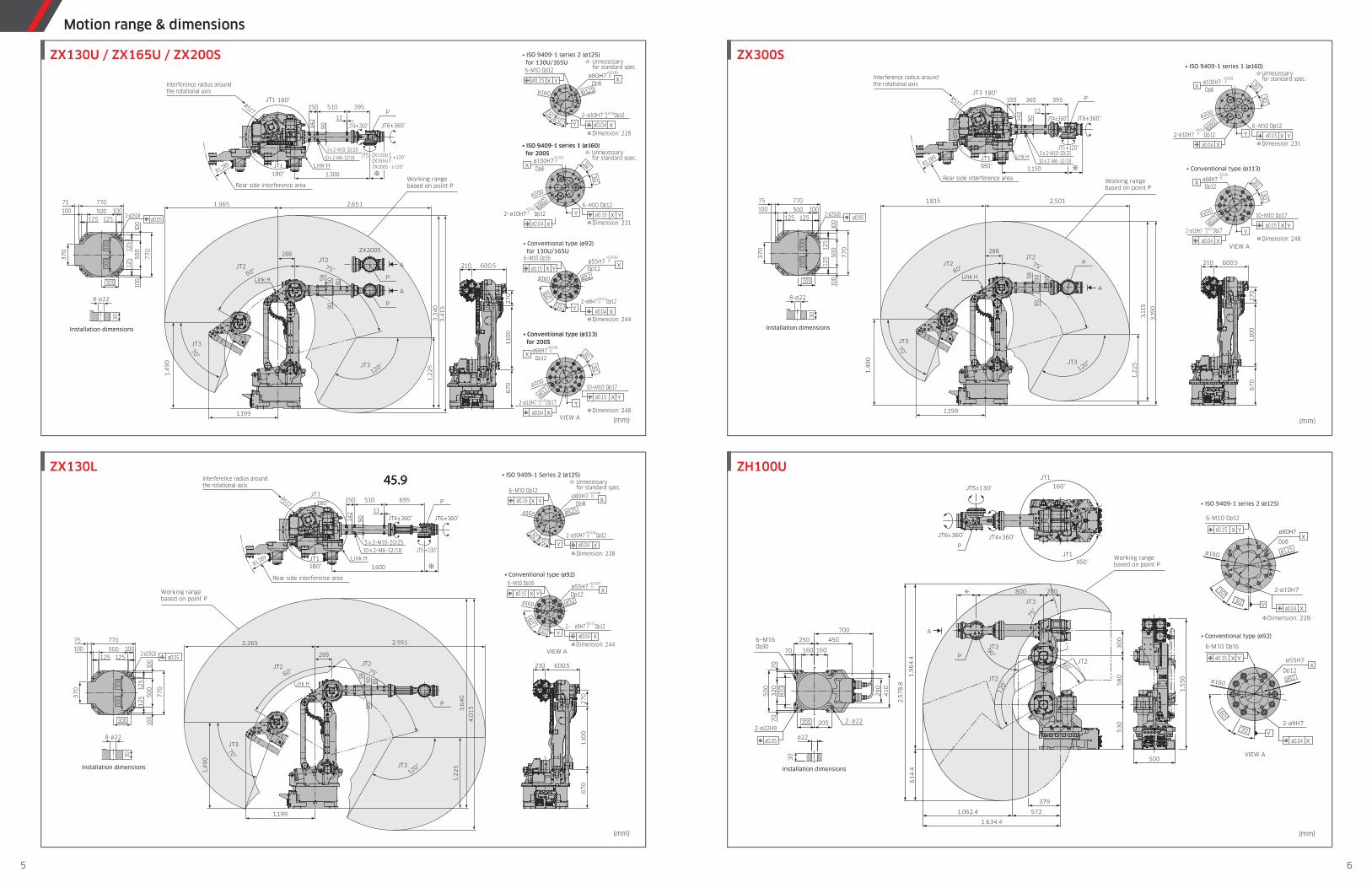
(mm)(mm)
ZT130Y/ZT165Y
ZT165XZT130U / ZT165U / ZT200S
Rear side interference area
Installation dimensions
ø0.05
2-ø25G8
ø55H7
59°
30°
30°
30°
6-M10 Dp12
6-M10 Dp12
2-ø9H7
ø80H72-ø10H7
X
Y
X
Y
65
°
150°
50°
120°
210
60
0.5
P
5x2-M10-20/25
142
15
0
13
51
0
90
39
5
10x2-M6-12/18
P
1,330
1,270
4,3
66
2,9
00
1,4
66
2,830
60
0
1,3
00
1,000530125
77
0
770
100 100500
10
01
00
50
012
51
25
125
75
37
0
30
JT3
JT3
JT2
JT2
JT1
JT1
8-ø22
300
300
300
JT6±360°
JT5±130°
JT4±360°
VIEW A
X Yø0.15
X Yø0.15
Xø0.04
Xø0.04
ø92
ø160
ø160
ø125
Dp8
Dp12
A
Dimension: 228
Dimension: 244
• Conventional type (ø92)
• ISO 9409-1 series 2 (ø125)
Working rangebased on point P
10 x
2–M
6–12
/18
5 x
2–M
10–2
0/25
142
1315
051
039
5
1,3
00
4,5
71
VIEW B
JT5±
130°
JT6±360°
JT4
±36
0°
ZT20
0S:±
120°
95°
58
809090
1,3
00
78
2,1
03
60
03001,100530
3,23080
180°
210
60
0.5
30
125
77
0
770
100 100500
100
100
50
012
512
5
125
75
37
0
Installation dimensions A
B
A
ZT200S
58
809090
1,7
31
JT1
180°JT1
ø0.05
8-ø22
2-ø25G8
JT3
JT2
JT2
60°
75°
90
300
300
300
JT3
16
5°
PP
Working rangebased on point P
YX
2–ø10H7 Dp12
Dimension: 228
Y
+0.015 0
Xø0.04
Y30°
60 °
Dimension: 244
+0.015 0ø9H7 Dp12
Xø0.04
ø160
• Conventional type (ø92) for 130U/165U
+0.030 0ø55H7
XDp12
6–M10 Dp16
X Yø0.15
ø92
Depth8X
+0.035 0ø100H7
• ISO 9409-1 series 1 (ø160) for 200S Unnecessary
for standard spec.
30 °
30 °
Dp12+0.015 02–ø10H7
Xø0.04 Dimension: 231
6–M10 Dp12
ø0.15Y
ø200
ø160
ø160
30°30°
+0.030 0ø80H7
XDp8
6–M10 Dp12
X Yø0.15
• ISO 9409-1 series 2 (ø125) for 130U/165U Unnecessary
for standard spec.
ø125
Dp12X
+0.030 0ø68H7
• Conventional type (ø113) for 200S
30°
30 °
VIEW A
Dp17+0.015 0
Xø0.04 Dimension: 248
10–M10 Dp17
X Yø0.15
ø200
2–ø10H7 Y
ø113
2–
ø0.05
180°
180°
8-ø22
30
37
0
75
125
12
51
25
50
01
00
10
0
500 100100
770
77
0
125
2-ø25G8
300
30
03
00
530 1,000
1,6
00
60
0
3,130
1,7
66
3,2
00
4,9
66
1,570
1,630
10x2-M6-12/18
69
5
90 51
0
13
15
0
142
5x2-M10-20/25
R970
210
120°
50°
150°
65
°
59
7.5
JT5±130°
JT1
JT1
JT4±360°
JT6±360°
JT2
JT2
JT3
JT3
P
PInstallation dimensions
Working rangebased on point P
Rear side interference area
Dimension: 228
Y
+0.015 02–ø10H7 Dp12
Xø0.04
ø160
30 °30°
+0.030 0ø80H7
XDp8
6–M10 Dp12
X Yø0.15
• ISO 9409-1 Series 2 (ø125)Unnecessaryfor standard spec.
ø125
Y30°
60 °
Dimension: 244Xø0.04
ø160
• Conventional type (ø92)+0.030 0ø55H7
XDp12
6–M10 Dp16
X Yø0.15
ø92
VIEW A
+0.015 0ø9H7 Dp122–
A
Motion range & dimensions
7 8
....
USB
RS-232C
DIO board
External-axis motor
Standard
Option
Optional board
Optional device
Ethernet
DeviceNet board, master/slave
CC-Link board, master/slave
PROFIBUS board, master/slave
PROFINET board, master/slave
Ethernet/IP board, master/slave
CAN open board, slave
EtherCAT board, master/slave
Cubic-S (area monitor/speed monitor)
Conveyor I/F board
Rapid-feed checkmode switch
Transformer unit
Teach pendant
Terminal software
Terminal software
Vision controller
USB memory
Brake release switch
DIO board: 32 points eachmax. 3 boards (96 points)
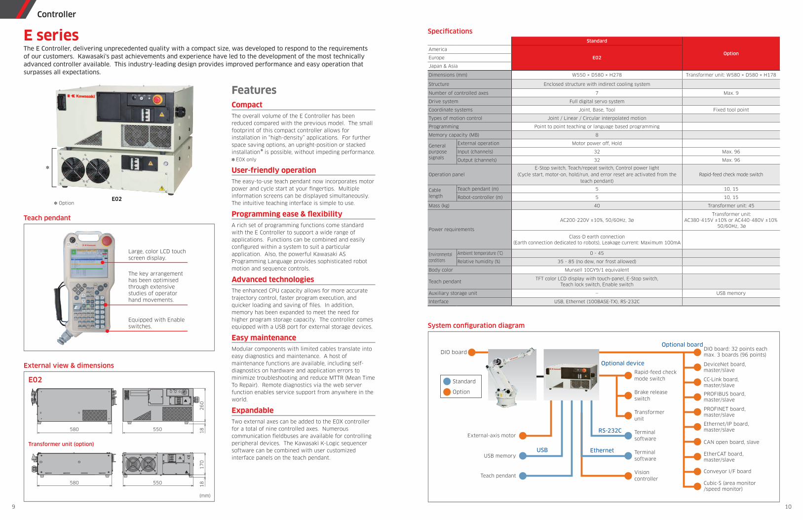
System con� guration diagram
Standard
OptionAmerica
E02Europe
Japan & Asia
Dimensions (mm) W550 × D580 × H278 Transformer unit: W580 × D580 × H178
Structure Enclosed structure with indirect cooling system
Number of controlled axes 7 Max. 9
Drive system Full digital servo system
Coordinate systems Joint, Base, Tool Fixed tool point
Types of motion control Joint / Linear / Circular interpolated motion
Programming Point to point teaching or language based programming
Memory capacity (MB) 8
Generalpurposesignals
External operation Motor power off, Hold
Input (channels) 32 Max. 96
Output (channels) 32 Max. 96
Operation panelE-Stop switch, Teach/repeat switch, Control power light
(Cycle start, motor-on, hold/run, and error reset are activated from the teach pendant)
Rapid-feed check mode switch
Cablelength
Teach pendant (m) 5 10, 15
Robot-controller (m) 5 10, 15
Mass (kg) 40 Transformer unit: 45
Power requirements
AC200-220V ±10%, 50/60Hz, 3øTransformer unit:
AC380-415V ±10% or AC440-480V ±10%50/60Hz, 3ø
Class-D earth connection (Earth connection dedicated to robots), Leakage current: Maximum 100mA
Environmentalconditions
Ambient temperature (°C) 0 - 45
Relative humidity (%) 35 - 85 (no dew, nor frost allowed)
Body color Munsell 10GY9/1 equivalent
Teach pendantTFT color LCD display with touch-panel, E-Stop switch,
Teach lock switch, Enable switch
Auxiliary storage unit — USB memory
Interface USB, Ethernet (100BASE-TX), RS-232C
Speci� cations
FeaturesCompactThe overall volume of the E Controller has been reduced compared with the previous model. The small footprint of this compact controller allows for installation in “high-density” applications. For further space saving options, an upright-position or stacked installation✽ is possible, without impeding performance.✽ E0X only
User-friendly operationThe easy-to-use teach pendant now incorporates motor power and cycle start at your � ngertips. Multiple information screens can be displayed simultaneously. The intuitive teaching interface is simple to use.
Programming ease & � exibilityA rich set of programming functions come standard with the E Controller to support a wide range of applications. Functions can be combined and easily con� gured within a system to suit a particular application. Also, the powerful Kawasaki AS Programming Language provides sophisticated robot motion and sequence controls.
Advanced technologiesThe enhanced CPU capacity allows for more accurate trajectory control, faster program execution, and quicker loading and saving of � les. In addition, memory has been expanded to meet the need for higher program storage capacity. The controller comes equipped with a USB port for external storage devices.
Easy maintenanceModular components with limited cables translate into easy diagnostics and maintenance. A host of maintenance functions are available, including self-diagnostics on hardware and application errors to minimize troubleshooting and reduce MTTR (Mean Time To Repair). Remote diagnostics via the web server function enables service support from anywhere in the world.
ExpandableTwo external axes can be added to the E0X controller for a total of nine controlled axes. Numerous communication � eldbuses are available for controlling peripheral devices. The Kawasaki K-Logic sequencer software can be combined with user customized interface panels on the teach pendant.
External view & dimensions
Equipped with Enable switches.
The key arrangement has been optimised through extensive studies of operator hand movements.
Large, color LCD touch screen display.
Teach pendant
E02✽ Option
✽
POWER
REPEATTEACH
420 500
25
0
26
01
81
81
70
9
POWER100% CONTROL
REPEATTEACHOFF ON R
PS OT
EM CG
E YNE
580 550
580 550
E02
(mm)
Transformer unit (option)
The E Controller, delivering unprecedented quality with a compact size, was developed to respond to the requirements of our customers. Kawasaki's past achievements and experience have led to the development of the most technically advanced controller available. This industry-leading design provides improved performance and easy operation that surpasses all expectations.
E series
Controller
9 10