kc streetcar - substation memo...
TRANSCRIPT
Kansas City Downtown Streetcar Project May 7th, 2012 Streetcar TPSS Siting Technical Memorandum Page | ‐ 1 ‐
Streetcar TPSS Siting Technical Memorandum
KANSAS CITY DOWNTOWN STREETCAR PROJECT Streetcar Traction Power Substation Siting Memo
May 7, 2012
1. Background The Kansas City Downtown Streetcar Project is a 2.2‐mile double‐track system that will operate north‐south along Main Street between Pershing Road and Seventh Street, then north onto Delaware Street proceeding to Fifth Street. The alignment will loop one‐way on Fifth Street east to Grand Boulevard, north to third Street, and then west to Delaware Street, continuing south on Delaware Street back to Fifth Street (returning to a double‐track system). The streetcar project is entering into the Environmental Process, and it has been requested that the project team identify possible traction power substation (TPSS) sites for planning considerations. Before specific sites can be identified, a general methodology must be identified. This memorandum identifies the selection process and begins to identify potential TPSS sites. It is proposed that the streetcar’s overhead contact system (OCS) utilize a simple single contact wire system. For planning purposes, it is assumed that the system will ultimately employ a maximum of six vehicles in operation at the same time (although initially there will be only three vehicles in operation for the first phase of system operation). It is further assumed that the overhead system will not be sectionalized and will operate as a common overhead. But it is also understood that the project team will eventually have to study and verify the final locations of the TPSS sites for performance and operational considerations while in preliminary engineering or final design. A final traction power supply report/study, to be performed in the design phase, will determine the exact number of required substations and may increase or decrease the number of TPSSs for the system.
2. Methodology
The selection of TPSS sites for streetcar systems is different from that for light‐rail systems. Generally, locating substations for streetcar systems is more a function of available sites (real estate) than of performance considerations. For light‐rail systems, traction power substations are generally located in mile intervals (or greater), with half‐spacing near the terminal ends of the alignment. Light‐rail substations are mainly located by traction power simulations or calculations based on peak headways, vertical grades, speeds, and other operational factors. Traction power substations for light‐rail systems tend to be larger in size and provide higher power output (0.5 megawatts to 1.5 megawatts). In contrast, streetcar substations are spaced in mile to half‐mile intervals and have smaller footprints. Streetcar traction power outputs are generally lower than those of light‐rail systems. The general approach used to locate substations is to first identify sites at ½ to 1 mile intervals. These sites are evaluated for available real estate, available power sources, and suitability for substation structures.
Kansas City Downtown Streetcar Project May 7th, 2012 Streetcar TPSS Siting Technical Memorandum Page | ‐ 2 ‐
Streetcar TPSS Siting Technical Memorandum
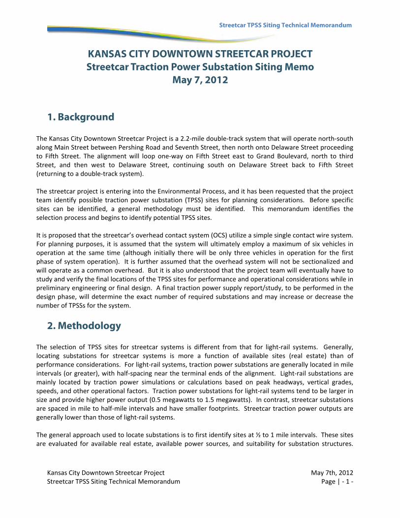
During design, sites are evaluated, via traction power calculations or traction power simulations, to determine actual spacing requirements and which sites they will utilize. . If it is found that the sites are not suitable because of environmental or real‐estate issues, a replacement site should be identified. Alternately, if a site was eliminated and the desired substation spacing was not be attainable, alternate substation configurations could be employed. This could include having fewer sites with larger substations, running a duct bank from one of the near by sites or underground substations could be considered. These issues will be identified and addressed during design. It is assumed, for the purposes of this analysis, that the maintenance and storage facility (MSF) will have its own substation for yard and internal train movements as well as adjacent main line operations. From a cost‐efficiency standpoint, it is assumed that prefabricated substations will be primarily implemented as opposed to custom field‐erected substations, unless it is found that custom substations are the only viable alternative based on field conditions. Below is a photo of a typical prefabricated substation; these facilities can be screened with trees and shrubs or “tucked away” as feasible so long as access is maintained.
Prefabricated Traction Power Substation
3. Planning Analysis
Kansas City Downtown Streetcar Project May 7th, 2012 Streetcar TPSS Siting Technical Memorandum Page | ‐ 3 ‐
Streetcar TPSS Siting Technical Memorandum
This preliminary analysis is for the sole purpose of identifying possible sites for traction power substations for the Environmental Assessment. The preliminary analysis conducted on the potential sites is a fatal flaw type analysis based on information provided by others that will need to be verified in final design. The final design team will be responsible for establishing the power service requirements for the system based on the capacity of the AC feeder, substation locations and power requirements of the system. In total, five substation locations, at roughly half‐mile spacing, were selected for evaluation. Some locations have multiple site options as shown on the attached exhibits. The possible substation locations are generally located at:
Main Street and Pershing Road
Main Street and 20th Street
Main Street and 16th Street (I‐670)
Delaware Street and 6th Street
Maintenance and Storage Facility (MSF)
4. TPSS Sites The site locations are constrained by the available land in the project area that meets the general spacing and size requirements. The site size requirements for a substation are somewhat variable and dependent on many factors and the overall design approach. For example substations spaced further apart which power longer segments are typically larger than closely spaced substations. Other factors which may effect the size of the substation include the power supply requirements and sectionalization. These design elements can also have a factor on the amount of equipment, breakers, cabinets, etc that need to be housed at the substation location/building and effect it’s size. In general the size of the substations vary from 10’ x 15’ on the smaller end to 15’ x 25’ for larger substations with an approximate height of 11’. These are “average” sizes that can vary (up or down) site by site and is dependent on the many factors as previously mentioned. The final location and size for each substation will not be determined until the project enters final design. As part of the overall analysis the project team evaluated each site to ensure, at a minimum, the site provided the following:
Reliable AC power source (preferably from underground)
Maintenance access ‐ easy to access from street
Necessary clear zones/size of site
Ability to secure location
Location not in a flood zone
Both the power supply and size requirements are approximate at this stage in the design process. The power supply evaluation was based on information provided from Kansas City Power and Light (KCP&L). Each proposed site was preliminarily analyzed for AC power availability to ensure that an adequate power supply source exists to support a 200‐300kw (typical of streetcars) substation at each of the potential locations. The attached exhibits identify a potential power source for each site and are illustrated with a 15’ by 25’ substation building for the purpose of illustrating the “larger” substation fits on the site.
Kansas City Downtown Streetcar Project May 7th, 2012 Streetcar TPSS Siting Technical Memorandum Page | ‐ 4 ‐
Streetcar TPSS Siting Technical Memorandum
Site 1 – Maintenance and Storage Facility (MSF) The TPSS to be located at the MSF would mainly power the yard and internal shop building movements. This unit would be considered the shop TPSS. However, this site could also house a TPSS unit to power the main line or could be incorporated into the shop TPSS unit that would power the internal building, yard, and main line. This TPSS site is to be examined in coordination with the selection of an MSF site currently anticipated on the north end of the alignment.
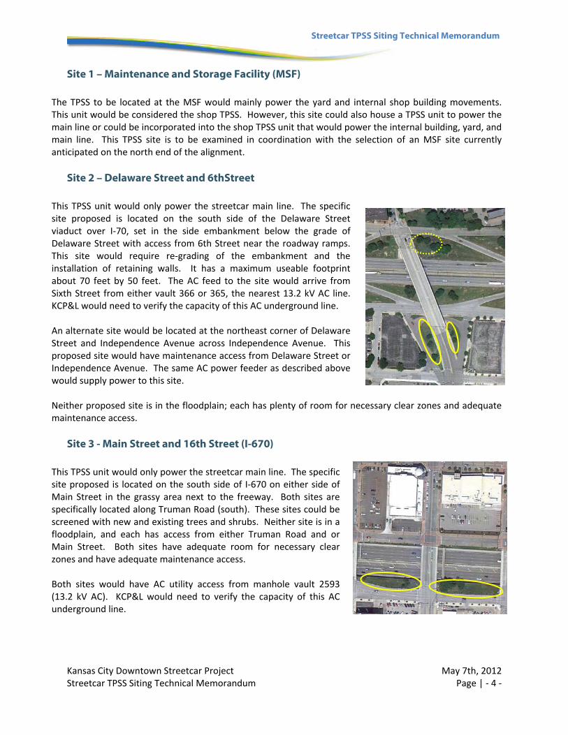
Site 2 – Delaware Street and 6thStreet This TPSS unit would only power the streetcar main line. The specific site proposed is located on the south side of the Delaware Street viaduct over I‐70, set in the side embankment below the grade of Delaware Street with access from 6th Street near the roadway ramps. This site would require re‐grading of the embankment and the installation of retaining walls. It has a maximum useable footprint about 70 feet by 50 feet. The AC feed to the site would arrive from Sixth Street from either vault 366 or 365, the nearest 13.2 kV AC line. KCP&L would need to verify the capacity of this AC underground line. An alternate site would be located at the northeast corner of Delaware Street and Independence Avenue across Independence Avenue. This proposed site would have maintenance access from Delaware Street or Independence Avenue. The same AC power feeder as described above would supply power to this site. Neither proposed site is in the floodplain; each has plenty of room for necessary clear zones and adequate maintenance access.
Site 3 - Main Street and 16th Street (I-670) This TPSS unit would only power the streetcar main line. The specific site proposed is located on the south side of I‐670 on either side of Main Street in the grassy area next to the freeway. Both sites are specifically located along Truman Road (south). These sites could be screened with new and existing trees and shrubs. Neither site is in a floodplain, and each has access from either Truman Road and or Main Street. Both sites have adequate room for necessary clear zones and have adequate maintenance access. Both sites would have AC utility access from manhole vault 2593 (13.2 kV AC). KCP&L would need to verify the capacity of this AC underground line.
Kansas City Downtown Streetcar Project May 7th, 2012 Streetcar TPSS Siting Technical Memorandum Page | ‐ 5 ‐
Streetcar TPSS Siting Technical Memorandum
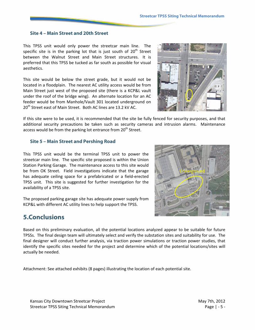
Site 4 – Main Street and 20th Street This TPSS unit would only power the streetcar main line. The specific site is in the parking lot that is just south of 20th Street between the Walnut Street and Main Street structures. It is preferred that this TPSS be tucked as far south as possible for visual aesthetics. This site would be below the street grade, but it would not be located in a floodplain. The nearest AC utility access would be from Main Street just west of the proposed site (there is a KCP&L vault under the roof of the bridge wing). An alternate location for an AC feeder would be from Manhole/Vault 301 located underground on 20th Street east of Main Street. Both AC lines are 13.2 kV AC. If this site were to be used, it is recommended that the site be fully fenced for security purposes, and that additional security precautions be taken such as security cameras and intrusion alarms. Maintenance access would be from the parking lot entrance from 20th Street.
Site 5 – Main Street and Pershing Road This TPSS unit would be the terminal TPSS unit to power the streetcar main line. The specific site proposed is within the Union Station Parking Garage. The maintenance access to this site would be from OK Street. Field investigations indicate that the garage has adequate ceiling space for a prefabricated or a field‐erected TPSS unit. This site is suggested for further investigation for the availability of a TPSS site. The proposed parking garage site has adequate power supply from KCP&L with different AC utility lines to help support the TPSS.
5.Conclusions Based on this preliminary evaluation, all the potential locations analyzed appear to be suitable for future TPSSs. The final design team will ultimately select and verify the substation sites and suitability for use. The final designer will conduct further analysis, via traction power simulations or traction power studies, that identify the specific sites needed for the project and determine which of the potential locations/sites will actually be needed. Attachment: See attached exhibits (8 pages) illustrating the location of each potential site.
Underground