kcfp annual report 2013 - lth · kcfp annual report 2013 ... lund university and the industry....
TRANSCRIPT

KCFP Annual Report 2013Centre of CompetenCe Combustion proCessesfaCulty of engineering, ltH | lund university


3KCFP AnnuAl RePoRt 2013
KCFP Centre of Competence Combustion ProcessesThe Centre of Competence Combustion Processes, KCFP, started July 1 1995.The main goal of this centre is to better understand the combustion process in internal combustion engines. Of particular interest are the combustion processes with low enough temperature to suppress formation of NOx and particulates, PM, often called Low Temperature Combustion, LTC or Homogeneous Charge Com-pression Ignition, HCCI.The Centre of Competence Combustion Processes has a budget of 22.25 MSEK per year. This is roughly one third each from the Swedish Energy Agency, STEM, Lund University and the Industry.
CONTENTS
The Partially Premixed Combustion Project 5
PPC - Heavy Duty 5
PPC - Light Duty 10
PPC - System Simulations 10
PPC - Modeling 12
PPC - Fuels 15
PPC - Control 17
The Generic Diesel Project 19
Lift-off Dependence on Multiple Engine Parameters 19Preparatory Work for In-Cylinder Soot Measurements 21
The Gas Engine Project 22
KCFP PhD Students who Graduated in 2013 25
INDUSTRY PARTNERS
Scania
Volvo GTT
Volvo Cars
Volvo Penta
Toyota
Caterpillar
Chevron
Wärtsilä
Finnveden
Hoerbiger
Cargine
The Swedish Gas Centre
Loge

4 KCFP AnnuAl RePoRt 2013
KCFP ORGANISATION
BOARDTommy Björkqvist, ordförande Annika Mårtensson, LTH
Johan Wallesten, Volvo GTT Ida Truedsson, LTH (PhD
Lucien Koopmanns, Volvo Cars student representative)
Per Lange, Scania
DIRECTORProfessor
Bengt JohanssonSupervisor for:
PPC
Administrator
Elna Andersson
Administrator
Catarina Lindén
ProfessorRolf Johansson
Supervisor for:CC
ProfessorMarcus Aldén
Supervisor for:PPC andGenDies
ProfessorXue-Song Bai
Supervisor for:CM
AssociateProfessor
Mattias Richter
Supervisor for:PPC and GenDies
ProfessorÖivind Andersson
Supervisor for:GenDies
AssociateProfessor
Martin Tunér
Supervisor for:Fuel
ProfessorPer Tunestål
Supervisor for:CC and SIGE

5KCFP AnnuAl RePoRt 2013
The Partially Premixed Combustion ProjectPartially Premixed Combustion, PPC, is a combustion process between Homogeneous Charge Compressi-on Ignition, HCCI and the classical diffusion control-led diesel combustion. With PPC it is possible to mo-derate the charge stratification and thus control the
PPC - Heavy Duty
The Effect of EGR and Engine Speeds on Partially Premixed Combustion
Mengqin ShenPhD Student
Partially premixed com-bustion is a promising way to achieve simultaneous high efficiency and low engine-out emissions in a heavy-duty engine. One of the key factors in PPC is EGR ratio. With large amount of EGR, The high-ly-diluted cylinder charge increases the ignition de-lay, thereby ensuring a highly premixed mixture that results in low NOX and soot emissions. However, the combustion could also become more sensitive to small changes in EGR - a slight increase in EGR can rapidly lower the combus-tion stability with a simultaneous sharp increase in the soot emissions.
Introduction
Figure 1 Single cylinder engine used in the study (left) and updated version used in the future (right)
Most previous PPC work has been done in the range of 1000-1300 rpm while the effect of higher speeds on PPC performance in a heavy duty engine is less known. It is expected that higher speed will increase the ignition delay and hence gives a preference to lower octane number fuels. It is not clear if engine operating conditions can offset this change in fuel requirement. An initial test was carried out to pro-vide a picture on this engine operation parameter.
Experimental SetupsThe research engine, Figure 1, is based on a Scania D13 heavy duty diesel engine. It is run on only one of the six cylinders and is equipped with a XPI com-mon rail system. In the study, the original piston with a compression ratio 18:1 was used. A high pressure, cooled EGR system was utilized and the EGR ratio is controlled by a EGR valve combined with a back pressure valve in the exhaust. Now the test bench is moved and updated in the new lab and will be used in the future research, as shown in Figure 1 on the right.
burn rate better than with HCCI. In comparison to classical diesel combustion the NOx and particulates can be suppressed with orders of magnitude. KCFP has five different but linked subprojects on PPC.

6 KCFP AnnuAl RePoRt 2013
EGR Effect
The fuels used in this experiment were Swedish die-sel MK1, a gasoline fuel of octane number (RON) 69. As shown in the EGR sweep in Figure 2, ignition de-lay increases as EGR ratio increases. Maximum pres-sure rise rate doesn’t change much for diesel while it drops in gasoline cases as EGR amount increases. Gasoline has longer ignition delay but also higher cy-linder pressure rise rate than diesel. EGR plays a vital role in reducing NOX emission while it increases soot emission as a penalty in diesel cases. For diesel fuel, soot emission is more sensitive to EGR increase when it reaches 30%.
Results
After reaching the peak value, soot emission drops when EGR continues to increase. UHC and CO emis-sions, as expected, increase with more EGR and the effect becomes more evident at high EGR (above 50%). Gasoline, compared to diesel, shows more UHC and NOX but almost no soot emission. CO emission level is similar to diesel but is almost half of what diesel has when EGR is more than 50%. For diesel fuel, EGR range is more limited first by soot then by CO, while gasoline is more limited by UHC and CO.
0 10 20 30 40 50 60
5
10
15
20
25
EGR [%]
MP
RR
[bar
/CAD
]
MK1Gasoline
0 10 20 30 40 50 60
5
10
15
EGR [%]
Igni
tion
Del
ay [C
AD
]
MK1Gasoline
Figure 2. Effect of EGR on ignition delay, maximum pressure rise rate (MPRR) and engine-out emissions for diesel and gasoline (IMEP gross ~ 5.5 bar, CA50~5CAD ATDC @ 1200 rpm, common rail pressure ~700 bar and single injection)
0 10 20 30 40 50 60
0
500
1000
1500
NO
x [p
pm]
0 10 20 30 40 50 600
1
2
3
soot
[FS
N]
EGR [%]
Soot-MK1Soot-gasolineNOX-MK1
NOX-gasoline

7KCFP AnnuAl RePoRt 2013
Engine Speed Effect
The fuel used was a gasoline fuel of octane number (RON) 89. Gasoline PPC performance over different engine speeds is presented in Figure 3. As engine speed increases, the pilot injection needs to be more advanced to have the same combustion phasing. In order to have the maximum pressure rise rate low, pilot injection ratio was increased. As expected, igni-tion delay increases as a function of engine speed. Combustion was not so stable at 1800 rpm and due to too long ignition delay it became more like HCCI combustion. Further investigation needs to be car-ried out at high engine speed.
Conclusion
EGR helps to increase ignition delay and decrease pressure rise rate. NOx can be largely reduced by EGR but with the penalty of soot (diesel fuel), UHC and CO. Soot can be reduced by very high EGR but too much UHC and CO emissions will lead to bad combustion. EGR range is limited by soot emission for diesel fuel and by UHC and CO emissions while operating on gasoline fuel. Ignition delay increases as a function of engine speed. To have low pressure rise rate, pilot injection ratio was increased as engine speed is higher. Combustion is not so stable at high
Future work
For 2014, the focus of PPC work will be more on the fundamental understanding of the combustion pro-cess. So the study of the effects/sensitivity of engine control parameters, like intake temperature, boost, intake oxygen concentration, injection strategies and combustion geometry will largely be carried out.
Figure 3. Cylinder pressure, injection current and rate of heat release of gasoline PPC over different engine speeds (IMEP gross ~ 6.5 bar, common rail pressure ~ 700 bars).
-40 -20 0 20 400
20
40
60
80
100
120
Crank Angle [CAD ATDC]Cyl
.Pre
ssur
e[ba
r]/R
oHH
/10[
J/C
AD]/I
nj.C
urre
nt Speed=900rpm
Cylinder PressureRate of Heat releaseInjector Current
-40 -20 0 20 400
20
40
60
80
100
120
Crank Angle [CAD ATDC]Cyl
.Pre
ssur
e[ba
r]/R
oHH
/10[
J/C
AD]/I
nj.C
urre
nt Speed=1000rpm
Cylinder PressureRate of Heat releaseInjector Current
-40 -20 0 20 400
20
40
60
80
100
120
Crank Angle [CAD ATDC]Cyl
.Pre
ssur
e[ba
r]/R
oHH
/10[
J/C
AD]/I
nj.C
urre
nt Speed=1150rpm
Cylinder PressureRate of Heat releaseInjector Current
-40 -20 0 20 400
20
40
60
80
100
120
Crank Angle [CAD ATDC]Cyl
.Pre
ssur
e[ba
r]/R
oHH
/10[
J/C
AD]/I
nj.C
urre
nt Speed=1300rpm
Cylinder PressureRate of Heat releaseInjector Current
-40 -20 0 20 400
20
40
60
80
100
120
Crank Angle [CAD ATDC]Cyl
.Pre
ssur
e[ba
r]/R
oHH
/10[
J/C
AD]/I
nj.C
urre
nt Speed=1799rpm
Cylinder PressureRate of Heat releaseInjector Current
engine speed due to too long ignition delay. More investigation is needed at high engine speed.

8 KCFP AnnuAl RePoRt 2013
PPC - Light Duty
Introduction
The current combustion engi-nes, equipped with exhaust gas recirculation and after-treatment systems, have been a good solution to achieve the emission standards, such as nitrogen oxide (NOx) and particulate matter (PM). Ho-wever, further efforts are necessary to find alternative combustion processes, which are able to reduce both NOx and PM without affecting fuel efficiency in particular operating conditions. For these reason, the advanced combustion technique - Partially Premixed Combus-tion (PPC) - is used to meet the increasing demands of emission legislation.
The aim of PPC – Light Duty project is to determine the degree of stratification of low load (towards idle) engine conditions. In this PPC-subproject optical in-vestigations carried out on a transparent modified engine. This investigations were performed for se-veral injection strategies with Negative Valve Over-lapping (NVO) settings, by using chemiluminescence imaging and high speed video with OH – filter. Also the usage of laser based measurement system is of interest to get cycle resolved data of the mixing pro-cess operating in PPC mode.
Experimental Setup
The research engine is based on a Volvo D5 light duty diesel engine. It is run on only one of the five cylin-ders and is equipped with a fully flexible pneumatic valve train system supplied by Cargine Engineering. The optical engine is also equipped with a bowditch piston extension. A quartz glass piston and ring was installed to enable optical access. The quartz ring was installed between the cylinder liner and the cylinder head to provide vertical images from the side around top dead center. The glass piston crown design is based on the standard diesel combustion chamber design with a bowl. The quartz glass piston enables horizontal images taken from underneath the com-bustion chamber. The geometric compression ratio is lower compared to the metal engine configuration and the engine is boosted to get the same pressure at fuel injection timing compared to the naturally aspirated metal engine setup. The intake air was heated to get the same combustion timing as a cor-responding metal engine reference case.
Results
The engine was run with gasoline fuel (RON69) at engine speed around 800 rpm. In order to investi-gate the degree of stratification of the combustion the intensity during the cycle have been detected.
Figure 1 shows a chemiluminiscence image of the combustion close after TDC. The picture is taken from below and the combustion chamber is divided in several radial bands. The five sprays are clearly re-cognizable and the red areas are indicating the high intensity of the sprays.
By using the 3D plot the spray intensity is pictured as a function of angle theta and crank angle of band number 6. This can be seen in figure 2 and figure 3. This figures are illustrating the same graph with a view from the front and back of five individual sprays. The red transparent bar is showing the injec-tion duration of the last fuel injection. A steep rise of the intensity after TDC is representing the combus-tion, which decreases for higher crank angle but it does not reach the abscissa.
Slavey TanovPhD Student
Figure 1. Chemiluminiscence image at 8 CAD; single injection

9KCFP AnnuAl RePoRt 2013
Figure 2. Intensity plot as a function of angle theta and crank angle – front side of the 5 individual sprays
Figure 3. Intensity plot as a function of angle theta and crank angle – back side of the 5 individual sprays
Following, the results of the degree of stratification for single, double and triple injection are pictured in figure 4. When comparing the different injection strategies, it can be observed that the in-homogen-eity index for single and double injection are almost the same. The triple injection shows a very low value for in-homogeneity, implying more stratified com-bustion.
Figure 4. Average in – homogeneity Index
Future Activities
Further work will consider more measurements in optical configuration for PPC mode by using diffe-rent combustion chamber and spray nozzle. The va-riable valve train system from cargine will be not in use in the future. The optical measurements will be performed with the original Volvo D5 camshaft.

10 KCFP AnnuAl RePoRt 2013
PPC - System Simulations
Introduction
Single cylinder research engi-nes provide an environment that can be precisely control-led and monitored to realize detailed research on combus-tion phenomena. One limit-ing factor with single cylinder engine research is that it typi-cally does not provide direct insight to the influence from the combustion on the gas ex-change process, total friction and heat losses and thus a production viable engine sys-tem as a whole.
To evaluate the potential of new combustion con-cepts, such as Partially Premixed Combustion (PPC), in a practical engine configuration, system simula-tions can be employed.
The aim of the PPC system simulations has been to determine if the very high indicated efficiencies and low emission levels recorded for PPC in single cylin-der engine research can be materialized in more fuel efficient and cleaner production viable PPC engines than the current state of the art diesel engines. This requires an understanding of the requirements on the gas exchange system, as well as a quantification of all potential loss sources.
Martin TunérAssociate Professor
System Model
The system model (figure 1) was built in GT-Power and is partly based on a validated Scania D13 EuroV production engine model. This means that compo-nents such as intake pipes and ports, exhaust ports and manifold, camshafts, valves, cranktrain etc. are essentially the same as for the production engine. Charge air cooler and EGR-cooler are based on the Scania designs but enlarged. EGR routing was chan-ged to a low pressure (long route) system. One major difference is the two-stage boosting system, which is an off-the-shelf system provided by BorgWarner.
The operating conditions for the 13 mode European stationary cycle (ESC) have been applied. Combus-tion data from the single cylinder PPC experiments run on 89RON gasoline were used where the system model was run at the same operating conditions as for the experiments (A-speeds). For B and C speeds the combustion data has been extrapolated based on several PPC experiments.
Figure 1. The multi-cylinder PPC engine system model.
Results
The results indicate that it is possible to operate a HD-PPC engine with a production two-stage boost system over the European Stationary Cycle while li-kely meeting Euro VI and US10 emissions. Peak brake efficiency reached 48.4% which is substantially hig-her than the typically reported 43% peak brake ef-ficiency for HD diesel engines. The HD-PPC engine does also demonstrate a large operating window with very high brake efficiency - a majority of the ESC can be operated with a brake efficiency above 44% (figure 2).
Exhaust temperatures stay above 230 °C throughout the ESC, which should be sufficient for a SCR system. Experiments indicate, so far, that a small SCR system could be necessary during low load PPC operation to meet EURO VI emission regulations.

11KCFP AnnuAl RePoRt 2013
A loss analysis for 75% load at 1250 rpm (figure 3) reveals that low in-cylinder heat transfer losses are the most important reason for the high efficiencies of PPC. In-cylinder heat losses are basically halved in PPC compared to CDC, as a consequence of substan-tially reduced combustion temperature gradients, especially close to the combustion chamber walls. Pumping losses are on the other hand three times higher than for CDC due to the increased mass flow rate over the valves from the charge dilution and the high amounts of EGR. Friction losses remain uncer-tain with respect to the direct injection of gasoline instead of diesel, but have been estimated to be slightly higher than for CDC.
Sensitivity analysis was performed by varying in-cylinder heat transfer, exhaust port + manifold heat transfer as well as overall engine friction. It could be concluded that further reduction of in-cylinder heat transfer losses is probably the most beneficial approach for further increase in brake efficiency. Further improvements can also be reached by redu-cing exhaust port and manifold heat transfer losses and optimized gas exchange and boosting systems. A PPC engine with 57% gross indicated efficiency, as demonstrated in single cylinder engine research, is likely to reach more than 50% brake efficiency.
43,0 48,1
2,72,91,03,1
41,240,5
12,0 5,30,1 0,1
0%10%20%30%40%50%60%70%80%90%
100%
CDC A75 PPC A75
Combustion Losses
Heat Transfer Losses
Exhaust Losses
Pumping Losses
Friction Losses
Figure 3. Comparison of loss terms in % of fuel energy between a typical CDC and PPC operating at similar load and speed.
Figure 2. Brake efficiency for the operating range covering ESC except idle.
Future Work
Future work will aim at producing additional experi-mental single-cylinder engine data (PPC-HD project) and validating the models for all operating points in the world harmonized stationary cycle (WHSC). With the updated models a second iteration boosting sys-tem can be investigated. Investigations with a real boosting system in multi-cylinder heavy duty engine can then be performed.
References
Tunér M., “Potential ESC13 Performance of a Multi-Cylinder Heavy Duty PPC Truck Engine. System Simu-lations based on Single Cylinder Experiments”, SAE Technical Paper 2013-01-0268, 2013.
Tunér M., Johansson B., Keller P., Becker M., “Loss Analysis of a HD-PPC Engine with Two-Stage Turbo-charging operating in the European Stationary Cy-cle”, SAE Technical Paper 2013-01-2700, 2013.

12 KCFP AnnuAl RePoRt 2013
PPC - Modeling
This approach is employed to capture the large-scale energetic motions and formation of vortices and in-stabilities that typically are responsible for fuel and air mixing and fuel/air entrainment. In synergy with the experimental and laser diagnostic research groups, the goal of the modeling project is to improve the understanding of the underlying fundamental flow and combustion in IC engines and to expand the knowledge about the performance of the modern PPC and diesel combustion engines.
Validation
The spray and combustion models for the LES have been evaluated and validated with external expe-rimental facilities, e.g., Sandia National Laborato-ries (spray A and spray N-heptane), and with opti-cal diagnostics from facilities within KCFP, such as the GenDies group. In the current simulations, the Chemistry Coordinate Mapping (CCM) method and the modified spray model, both previously described, are used. The CCM method is capable of employing additional dimensions in the phase-space to increase the accuracy of the results with contemporary re-duction of CPU cost, using extensive skeletal kinetic mechanisms. Incorporated into the spray model is stochastic turbulence dispersion and spray-induced turbulence consideration, which allows for a more physical description of the fuel spray/air entrainment process. The mesh motion is treated by a dynamic cell add/removal or mesh deformation approach, to ensure low aspect ratio of the mesh. The chemistry/turbulence interaction is modeled using a time-scale model, which requires direct integration of the che-mical kinetic rates into the flow transport simulation. The mixing and transport processes on the sub-grid scale are modeled using a one-equation eddy model.
Focus
Throughout the year, the focus has been on investi-gating the differences in fuel and air distribution with varying umbrella angles in a light-duty PPC engine and how the umbrella angle may influence the emis-sions and combustion efficiency. Furthermore, in collaboration with the experimental and optical di-agnostics group, effort has been on the role of mul-tiple injections in a light-duty PPC engine and how advanced injection strategies affect combustion con-trol. In collaboration with the GenDies group, work has been performed based on previous investigations in optical accessible heavy-duty engine with SLIPI, to analyze the effect of injection pressure on fuel and air mixing in the jets and in the recirculation region generated from jet-wall impingement.
Optical Light-Duty PPC Engine Investigation
Experimental investigations were carried out in an optical LD PPC engine for the injection strategy, Fi-gure 1. The results exhibited very different engine efficiencies and emissions. The aim of the modeling work was to investigate the fuel and air distribution, both in the squish and bowl region respectively, but also globally, in order to provide details on the dyna-mic development of the flow and mixing process. The results from non-reacting flow simulations suggested that for a narrow injection umbrella angle strategy, the mixture in the squish region is very lean and the mixture in the bowl region is very rich. For the broad umbrella angle, the mixture was found richer in the squish region and leaner in the bowl region. The re-sults can be used to optimize the injection timings and choice of umbrella angle.
Introduction
The aim of the KCFP mo-deling project is to perform detailed simulations of Par-tially Premixed Combustion (PPC) engines and classical diesel combustion engi-nes. Large Eddy Simulation (LES) is utilized as a tool to simulate the flow and combustion events in order to provide with high spatial and temporal resolution.
Rickard SolsjöPhD Student

13KCFP AnnuAl RePoRt 2013
3.0 CAD 5.0 CAD 7.5 CAD 9.5 CAD 1.0 CAD a) b) c) d) e)
f g) h) i j)
Figure 2. Image sequence of experimental OH-chemiluminescence (Figs. 2a-e) and line of sight OH field from LES (Figs. 2e-j) between 1 CAD after TDC and 9.5 CAD after TDC.
The work was continued by investigating the se-quential behavior of PPC combustion in the same engine at similar conditions, for PRF fuel. It was shown that with triple injections, the first and second injection generates a stratified mixture in the bowl region, which undergoes low-temperature reactions. The auto-ignition is initiated in the fuel-lean regions and the main heat-release occurs when the fuel from the last injection reaches the hot-reservoirs. Figure 2 shows the time sequence, comparing experimentally
Figure 1. Target points for the different umbrella angles (left) and PDF of the fuel and air distribution at 5 CAD aTDC (right).
obtained OH chemiluminescence with “numerical” line-of-sight OH field, where the OH from the LES is integrated along the piston axis. Figure 3 shows the in-cylinder distribution of equivalence ratio as a function of CAD, superimposed with temperature iso-lines indicating the high-temperature and low-temperature combustion sequence. In Figure 3, it is seen that the combustion is initiated at equivalence ratio around 0.5 and thereafter spread to leaner and richer regions.

14 KCFP AnnuAl RePoRt 2013
Equivalence ratio T=1200 K
T=1400 K
T=1600 K
T=1800 K
T=2000 KT=2200 K
T=2400 K
T=2400 K
T=2600 K
Figure 3. The in-cylinder distribution of equivalence ratio as a function of CAD. The vertical axis indicates the percentage of the engine volume at each CAD that is occupied by a fuel/air mixture of a given equivalence ratio. Equivalence ratio above unity is shown in red. The temperature distribution is shown using iso-contours between 1200 K and 2600 K.
Mixing in Wall-Jets in a HD Diesel Eng-ine
This work was based on the work by Clement Char-tier and Johan Sjöholm, employing SLIPI to investi-gate the effect of injection pressure of equivalence ratio in a wall-impinging jet and in the recirculation zones of the jet-wall impingement regions. The nozz-le setup is shown in Figure 4, where iso-surfaces of fuel mass fraction within which 99% of the total fuel is shown.
The results support the hypothesis that the effect of enhanced turbulence- and vortex-generation in the wall jet in the recirculation zone is weaker than the effect of engine confinement, due to the presence of adjacent jets. This was investigated for two injection pressures, 2000 bar and 2500 bar. This is in contrast to single wall-jets, where enhanced turbulence and development of vortices tend to decrease the equi-valence ratio in the recirculation zone for elevated pressure.
Figure 4. Mesh topology with iso-contours of mass frac-tion of iso-octane, Yf=0.01.
15KCFP AnnuAl RePoRt 2013
PPC - Fuels
Hadeel SolakaPhD Student
Introduction
The PPC Fuels project is ai-med at improving the under-standing on how and why specific fuel properties affect partially premixed combus-tion, but also on how to ex-ploit these properties for im-proved engine efficiency and reduced emissions. In short: what is the best PPC fuel and what is the best PPC engine for any given fuel? The research at LU has so far de-monstrated that PPC has an impressive fuel flexibility that cannot be matched by either Otto or diesel com-bustion principles. With the same engine hardware, fuels ranging from high cetane fuels such as diesel to high octane fuels such as gasoline and ethanol can all be operated in PPC. The different fuels have been demonstrated to offer similar peak efficiencies in PPC operation, but with substantial differences in emis-sions and load range performance. The underlying reasons for the differences are understood to some extent, but several aspects are less well understood and require further research.
Surrogate Fuel Component Influence on Partially Premixed Combustion
For 2013 the focus has been to develop a metho-dology to isolate and investigate the influence from individual fuel components typically found in com-mercial fuels such as diesel, gasoline, biodiesel and E85; namely aromatics, alcohols, isoparaffins and n-paraffins. By using the reference fuels isooctane (iso-paraffin), n-heptane (n-paraffin), toluene (aromatic) and ethanol (alcohol) together with a design of ex-periments (DoE) approach, the influence from each component as well as the interactions between the components can be quantified (figure 1).
0 7.5
15 0
5 10
30
35
40
Toluene [%] Ethanol [%]
n-Heptane [
Figure 1. The central composite two-level full-factorial de-sign employed. Balance of fuel fraction consists of isooctane.
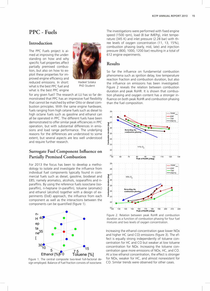
The investigations were performed with fixed engine speed (1500 rpm), load (8 bar IMEPg), inlet tempe-rature (345 K) and inlet pressure (2.28 bar) with th-ree levels of oxygen concentration (11, 13, 15%), combustion phasing (early, mid, late) and injection pressure (800, 1000, 1200 bar) resulting in a total of 612 engine experiments.
Results
So far the influence on fundamental combustion phenomena such as ignition delay, low temperature reaction fraction and combustion duration, but also the influence on emissions has been investigated. Figure 2 reveals the relation between combustion duration and peak RoHR. It is shown that combus-tion phasing and oxygen content has a stronger in-fluence on both peak RoHR and combustion phasing than the fuel composition.
50 60 70 80 90 100 110 120 130
21
22
23
24
25
26
27
28
29
Com
bust
ion
dura
tion
[deg
]
Peak of RoHR [J/deg]
11% O2
TERFcritic
ERFTRFPRF70
Retarding thecombustion phasing
120 130 140 150 160 170 180 190 200 210 220
21
22
23
24
25
26
27
28
29
Com
bust
ion
dura
tion
[deg
]
Peak of RoHR [J/deg]
15% O2
TERFcritic
ERFTRFPRF70
Retarding thecombustion phasing
Figure 2. Relation between peak RoHR and combustion duration as a function of combustion phasing for four fuel mixtures and two levels of oxygen concentration.
Increasing the ethanol concentration gave lower NOx and higher HC (and CO) emissions (figure 3). The ef-fect is equally strong independently of toluene con-centration for HC and CO but weaker at low toluene concentration for NOx. Increasing the toluene con-centration gave more emissions of NOx, HC, and CO. At a low ethanol concentration, the effect is stronger for NOx, weaker for HC, and almost nonexistent for CO. Similar trends were observed for other cases.

16 KCFP AnnuAl RePoRt 2013
It has previously been reported that fuels with aro-matics extend the duration of NOx formation due to local high temperature regions with combustion of decomposed hydrocarbons. HC and CO increased with increasing ethanol and toluene concentrations, since SOI had to be advanced to maintain CA50. An earlier SOI places more fuel in the squish volume, which has less chance to be fully oxidized because it might be trapped in overly lean zones, rich zones, or liquid fuel film.
Ethanol [%]
Tolu
ene
[%]
0 1 2 3 4 5 6 7 8 9 100
5
10
15
HC
[g/k
g Fu
el]
1.4
1.6
1.8
2
2.2
2.4
2.6
2.8
3
Ethanol [%]
Tolu
ene
[%]
0 1 2 3 4 5 6 7 8 9 100
5
10
15
NO
x [g/k
g Fu
el]
0.09
0.1
0.11
0.12
0.13
0.14
0.15
0.16
0.17
0.18
Figure 3. Emission index for HC and NOx HC as a function of fuel composition at baseline (CA50 at 6 CAD, 13% O2, and injection pressure at 1000 bar)
2 4 6 8 10 12 14 16
0
0.1
0.2
0.3
0.4
0.5
0.6
0.7
0.8
0.9
Smok
e [F
SN]
CA50 [deg]
InjP 800 barIjnP 1000 barInjP 1200 bar
PRF60TRFERF
Figure 4. Smoke as a function of combustion phasing for different injection pressures at 13% inlet oxygen concen-tration (n-heptane concentration was kept constant at 40%; toluene 15% and ethanol 10%)
Parameters Effect on �Indicated Coefficient
Retarding CA50 ↓ 0.27
Increasing inlet O2 concentration
↑ 0.22
Injection pressure - 0.0003
Increasing N ↑ 0.04
Increasing T - 0.003
Increasing E ↓ 0.028
Table 1. Fuel composition and derived parameter coeffi-cient effects on gross indicated efficiency.
Ongoing Work: Using Oxygenated Ga-soline Surrogate Compositions to Map RON and MON
There is a direct link between fuel composition and RON value for primary reference fuels (PRF). Howe-ver, with various blends of n-heptane, isooctane, toluene and ethanol no such link exists. Primarily this investigation address the problem using a reg-ression model from design of experiment (DoE) to map the fuel component space with respect to RON and MON. Secondly, the relation between ignition delay and RON is being examined in PPC. Finally, the possibility to control the combustion events by using fixed ignition delay for different fuels with different compositions is examined.
References
Solaka H., Tuner M., Johansson B., “Analysis of Sur-rogate Fuels Effect on Ignition delay and Low Tem-perature Reaction during Partially Premixed Combus-tion”, SAE Technical Paper 2013-01-0903, 2013.
Solaka H., Tuner M., Johansson B., Cannella W., “Gasoline Surrogate Fuels for Partially Premixed Combustion, of Toluene Ethanol Reference Fuels” SAE Technical Paper 2013-01-2540, 2013.
For the investigated parameter space it could be ob-served that changes in the oxygen concentration had a greater impact on emissions than changing the ra-tios of ethanol and toluene. Injection pressure had hardly any impact on HC, CO and NOx emissions but
was an important factor, together with the fuel com-position and combustion phasing, on smoke levels (figure 4). TRF that contains the highest aromatics content is believed to increase the flame temperature which, especially at the upstream location where the fuel concentration is much higher, increases the local soot concentration since the soot oxidation rate is hindered by the insufficient oxygen concentration.
The fuel composition had very small impact on both combustion efficiency and gross indicated efficiency (table 1). The influence from either combustion pha-sing or oxygen concentration is much stronger.

17KCFP AnnuAl RePoRt 2013
PPC - Control
Introduction
The project will focus on real-time optimization of the ef-ficiency. This means real-time decision making about injec-tion strategy (one, two or many injections) and charging system with EGR and boost pressure as main parameters. The engine will be operated both in stationary points and (simplified) transients.
PPC Combustion Rate Control
Gabriel Ingesson
PhD student
Gabriel IngessonPhD Student
Lianhao Yin PhD student
Lianhao YinPhD Student
In PPC, as in all internal combustion engine concepts it is of high importance to control the combustion processes in the cylinder. The combustion timing has to be chosen in order to maximize thermodynamic efficiency while the combustion rate has to be slow enough in order to fill constraints on maximum pres-sure and pressure rise rate. Also in PPC (as the name suggests) one wants to obtain a partially premixed combustion which has different combustion rate characteristics than for instance conventional diesel combustion.
In order to control the combustion process, the idea is to estimate the heat release rate from measured in-cylinder pressure in real-time and to use this as feedback information to a model-based controller, the controller objective would then be to obtain the pre-specified combustion performance and reliabi-lity. The idea is that the controller should be able to accomplish this by deciding a suitable multi-injection strategy.
A first step in this research will be to obtain a better understanding of the relation between injection and combustion in the PPC engine, this will be accom-plished by performing system identification on the combustion process.
So far a PPC Simulink model has been implemented and tested with validated parameters from previous works by Anders Widd, the idea here was to vary the injection timing and see what results the model gave. Some results are displayed in Figure 1.
Figure 1. Simulation results that shows normalized pressure and RoHR, together with rate of fuel mass injected
These simulations were done to investigate the mo-del output for different fuel injection inputs.
Experiment Bench Set Up
A multi-cylinder engine from Scania will be used as test platform for PPC combustion. The online effi-ciency optimization work and multi-cylinder PPC control work will be performed on this engine.
To accomplish these tasks, each cylinder will be equipped with individual cylinder pressure sensors and individual manifold pressure and temperature sensors, hardware from National Instrument will re-place the ECU from Scania for controlling the engine as Fig. 2 shows.
Figure 2. Experiment bench configuration
PPC Combustion Sensitivity Analysis
Based on previous PPC combustion measurements by Vittorio Manente, the ignition could be described by parameters of equivalence ratio, pressure, tem-perature, octane number in the following equation.

18 KCFP AnnuAl RePoRt 2013
Figure 3. Modeling errors in all operation point and octane number
The fitting equation could be used for predict the ignition delay with R-square 0.9942 which illustrate good fitness. In the low load under 5 bar the er-ror is significantly larger than other points and the premixed proportion is very low. It is thought that the ignition delay feature is highly influenced by the premixed proportion and the model illustrated above should provide good predictive results in more pure PPC.
The parameters of cylinder pressure, octane number, equivalence ratio, EGR and temperature are analy-zed. The sensitivity is illustrated by following value:
SSE R-square Adjusted R-square RMSE
28 0.9942 0.9939 0.5416
Table 1. Goodness of ignition delay model fitting
Higher value of Kx indicate x could be better control parameter for ignition delay. The result shows, as in Tab.2, pressure is highest, while, temperature lowest. The EGR, Octane number and Equivalence ratio has similar influence on ignition delay with 60% sensiti-vity. Therefore, cylinder pressure should be selected as direct and fast control parameter and EGR and equivalence ratio could be indirect and slow control parameter for ignition delay.
Parameter Cylinder pressure
Octane number
Equivalence ratio EGR temperature
Sensitivity 127% 60% 60% 60% 24%
Table 2. Sensitivity analysis result
Future Work
Modeling work in order to describe the relationship between multiple injections and heat release will be performed. Experiments will be performed on both single-cylinder and multi-cylinder engines.
Combustion timing, duration and efficiency sensiti-vity experiments will be performed on a single cylin-der engine.
Cylinder to cylinder and cycle to cycle dispersion will be studied on the multi-cylinder engine as well as methods for controlling them.
Methods for obtaining maximum brake efficiency will also be studied on the multi-cylinder engine.

19KCFP AnnuAl RePoRt 2013
The Generic Diesel Project
Although the soot formation rate is important for predicting soot emissions in absolute values, previous GenDies results have suggested that the in-cylinder soot oxidation rate explains most of the trends in soot emissions. These results were based on a small dataset obtained from an optical engine. To confirm these conclusions, a correlation analysis was perfor-med on a larger dataset obtained from a multicy-linder diesel engine. The main results are presented below.
Meanwhile, a laser extinction setup has been develo-ped and further refined for measuring the late-cycle soot oxidation. It is currently installed on the optical heavy-duty diesel engine and experiments are under-way.
Lift-off Dependence on Multiple Engine ParametersIt has been shown within the GenDies project that the flame lift-off length is affected by interactions between neighboring jets and the in-cylinder flow. These are parameters that are difficult to study in spray vessels. An effort has been initialized to create a database of lift-off lengths measured in an optical diesel engine, with the aim of providing CFD mode-lers with a valid reference set for predicting lift off lengths in engines.
The preliminary results presented here constitute the first phase of this effort. Lift off lengths were mea-sured under variation of intake temperature, gas density at top dead center, injection pressure, intake oxygen concentration, and nozzle orifice diameter. Other parameters, such as the swirl ratio and the inter-jet angle, will be added in future campaigns.
Lift-off lengths were measured in an optical die-sel engine using an innovative chemiluminescence technique. The combustion was imaged on a high-speed video camera equipped with an image inten-sifier and a stereoscope. An interference filter cen-tered on a strong OH* line (310 nm) was placed in front of one of the stereoscope openings. In front of the other, an “off-line” filter (centered on 330 nm) was placed. This collected the flame background, e.g. soot luminosity. By subtracting the latter image from the former, most of the background was remo-ved from the OH image. Figure 1 shows an example of such a stereoscopic image.
Figure 1. Stereoscopic combustion image showing the OH* with a background of soot radiation (left) and only the background (right).
The diesel engine is an im-portant power source for road transport. This is due to its relatively high ef-ficiency, though its emis-sions of nitrogen oxides and particulates remain challenging. Its importan-ce can be expected to in-crease as the demands on fuel efficiency increase. The Generic Diesel (Gen-Dies) project currently studies various in-cylinder mechanisms that explain trends in soot emissions.
Defined as the distance between the nozzle and the flame, the lift-off length constitutes the spatial extent over which air can be entrained befo-re the fuel burns. Greater air entrainment over this distance translates into less soot formation. The lift-off length is thereby central to the soot proces-ses in burning diesel jets. Unfortunately, it is difficult to predict lift off lengths using traditional CFD codes. For this reason, a lift-off measurement campaign was carried out with the aim of providing a dataset for calibration of CFD models.
Guillaume LequienPhD Student
Ted LindPhD Student
Yann GalloPhD Student

20 KCFP AnnuAl RePoRt 2013
-5 0 5 10 15 20
0
5
10
15
20
25
30
Crank Angle [CAD]
Lift-
off L
engt
h [m
m]
Downswirl Spray at 12Upswirl Spray at 12Downswirl Spray at 6Upswirl Spray at 6Downswirl Spray at 3Upswirl Spray at 3
Figure 2. Evaluated lift off lengths from the stereoscopic high-speed video movie.
Correlation Analysis of the Ro-les of Soot Formation and Oxi-dationPrevious results from our laboratory have shown that the local equivalence ratio f at the lift-off length cor-relates poorly with soot emissions. This f-value is coupled to the soot formation rate in burning die-sel jets. The results suggested that the soot oxida-tion process was more important for understanding trends in soot emissions.
Two important drawbacks of the previous study were the relatively small dataset and the fact that the op-tical engine had an atypical combustion chamber. Here, a dataset from a near-production multicylinder diesel engine is analyzed to complement the previous results. The equivalence ratio at the lift-off length is estimated with an empirical correlation and an idea-lized model of a diesel spray. A regression model de-scribing soot emissions as function of global engine parameters influencing soot oxidation is also propo-sed. Overall, the results of this analysis confirm that trends soot emissions are best understood in terms of the efficiency of the oxidation process.
Figure 3 shows the measured soot emissions as fun-ction of f at the lift-off length. The latter was esti-mated using an empirical relationship obtained from
Figure 3. Soot versus f at lift off, which is used as a proxy for the soot formation rate.
Figure 2 shows evaluated lift off lengths as function of crank angle position, evaluated from the stereos-copic movie. Two lengths are evaluated from each spray, as the upwind side of the jet (in relation to the swirl flow) tends to have a longer lift off length than the downwind side. The 12 o’clock, 3 o’clock and 6 o’clock sprays were used for analysis. The dataset is not yet fully analysed, and the final results will be presented in a future report.
The variables most clearly linked with the measu-red soot emissions were the intake oxygen concen-tration, the combustion phasing (CA50), the load (IMEP), and the decay rate of the rate of heat release after the end of injection. Fitting a single exponen-tial decay function to this part of the heat release curve provided a half-life f, which correlated with the soot emissions. Although some of these parame-ters also affect the soot formation rate, it was shown that their dominant effect on the soot emissions was through the soot oxidation process. These variables resulted in the following power-law relationship with the soot emissions.
Equation 1:
Soot ∝CA501.52τ 2.5IMEP1.59O2−10.33
the spray vessel at Sandia, along with established jet theory. Although the absolute f values are probably wrong, it should be noted that the trends will be cor-rect, which is all that is required for the correlation analysis. The figure clearly shows the lack of correla-tion between the two variables.

21KCFP AnnuAl RePoRt 2013
Diode‐laser
Acousto‐opticmodulator (AOM)
Re‐collimation lens
Photodiode(reference)
Beamsplitter
Re‐collimation lens
Photodiode(transmission)
Collection lens
Telescope lenses
Engine
Figure 1. Experimental setup for the LEM campaign
Preparatory Work for In-Cylinder Soot MeasurementsFor the laser/optical part of the LEM cam-paign the optical setup has been built and tested in the optical lab. The experimen-tal setup can schematically be seen in Fig. 1. The Acousto-Optic Modulator (AOM) which modulates the laser is controlled by a pulse generator which is triggered by the crank angle signal from the engine (one pulse per 0.2 crank angle degree). For an engine running at 1200 rpm, this results in a laser beam modulated at 72 KHz.
For data acquisition a LabVIEW program has been written. This program collects signals from four different sources. Two of these are photodiodes, measuring the power of a reference laser beam and of the laser beam which passed through the engine. To be able to link the measured data to the correct engine cycle, the top dead center (TDC) signal and the raw sig-
Johan SimonssonPhD Student
Zheming LiPhD Student
nal from CAD encoder (giving one pulse each 0.2 crank angle) are also sampled.
The developed LabVIEW program has the possibility to calculate and show the extinction, i.e. the soot concentra-tion along the beam path, vs. crank angle degree while the engine is running. This to verify that everything work as intended. However, this option should not be used while performing the actual measurements since it requires sub-stantial processor power due to the massive amount of data collected (a total of 10 million samples each second). This feature has, however, been tested successfully with simula-ted signals. Corresponding test in the engine is planned for early 2014.
As seen in Figure 4, this relationship explains 92% of the variation of the dataset’s soot emis-sions. This strongly supports the previous con-clusion that soot oxidation is the dominant pro-cess governing trends in soot emissions from diesel engines.
Figure 4: Soot predicted by the regression model ver-sus measured soot. An R2 of 0.92 means that the mo-del explains 92% of the variation in the soot emissions.

22 KCFP AnnuAl RePoRt 2013
The Gas Engine ProjectIntroduction
The Gas Engine Project at Lund Uni-versity aims to explore and understand the combustion phenomenon in engine operating on gaseous fuels and develop technologies as an alternative to present day diesel operated heavy duty engines which are facing severe challenges like stringent emissions norms, high techno-logy cost and unsustainable fuel supply. Over the past few years, Natural Gas has emerged as the most promising gaseous fuel due to its benefits in terms of emis-
Background
Earlier in this project, experiments were performed using a multi-cylinder heavy duty engine to com-pare its performance and emission characteristics when operated with un-fueled pre-chamber spark plug and a conventional spark plug. Results showed marginal increase in operating lean limit with ex-cess air and dilution limit with EGR, however, there was substantial reduction in the flame development
angle and combustion duration while the combustion was much more stable (low coefficient of variation of IMEPg), which implied that spatially distributed jets from a pre-chamber spark plug offered a better ignition source than a single point spark. Even so, the main purpose of exploring an alternative ignition technique, which was extension of lean and dilution limit of operation, was not being served. The rea-son behind this was believed to be over-leaning of mixture in the pre-chamber by
Ashish ShahPhD Student
sion reduction with cheap after treatment devices and increasing fueling station network worldwide. The current phase of this project focuses on exploring alternative ignition techniques as after completion of all previous phases it was observed that the capability of conventional spark plug ignition system was the factor limiting the extent of dilution and hence emis-sion reduction and efficiency improvement in heavy duty natural gas engines.
Two most feasible alternative ignition systems were identified, namely diesel pilot injection and pre-chamber type ignition system but it was soon rea-lized that the former has already received conside-rable attention and has been commercialized under different names like The Hardstaff OIGI® (Oil Igni-tion Gas Injection), Westport’s High-Pressure Direct Injection (HPDI) applicable to a wide range of engi-nes. Comparatively, however, the concept of pre-chamber ignition has received limited attention and is mainly applied to stationary or large bore marine engine which do not face as severe speed and load transients as experienced by a heavy duty engine for mobile application. Reasons behind this are believed to be limited knowledge about the mechanism of ig-nition resulting from a pre-chamber type ignition de-vice and hence gaining deeper insight into this me-chanism is currently the objective of the gas engine project.
residual gasses in absence of any scavenging mecha-nism to flush the pre-chamber in the beginning of every cycle.
As already detailed in the previous annual report, a literature survey was conducted and it was soon identified that additional fueling to the pre-chamber will help scavenge the residual gasses and also form a easily combustible mixture in the pre-chamber while the main chamber is extremely lean. There are at least two strategies of operation with fueled pre-chamber, having a near stoichiometric mixture in the pre-chamber and having a fuel-rich mixture in the pre-chamber. The later, also referred to as LAG-igni-tion process, is relatively less explored but has docu-mented benefits over the former technique. Howe-ver, its applicability to heavy duty engines operating with natural gas is unexplored and hence is the focus of current study.
Experimental Work
A single cylinder heavy duty setup was prepared out of a 6 cylinder Scania D13 diesel engine. The active cylinder was modified to reduce the compression ratio of 12 and natural gas fueling system for the main and pre-chamber was installed, as depicted by the schematic layout in figure 1. A pre-chamber as-sembly capable of spark ignition, fuel injection and pressure measurement was prepared and is shown in figure 2. Pre-chamber volume and nozzle dimension were set to match the recommendation of L. A. Gus-sak who first proposed the LAG-ignition process.
First set of experiments performed were to study the effect of relative excess air ratio between the pre- and main chamber and also to evaluate the lean limit of operation with excess air.

23KCFP AnnuAl RePoRt 2013
Figure 2. A cross sectional and isometric view of pre-chamber assembly
Figure 1. Layout of experimental setup. a) Cylinder, b) Dy-namometer, c) Intake air pressure regulator d) Intake air flow meter, e) Intake surge tank, f) EGR mixing tank, g) Th-rottle valve, h) Exhaust surge tank, i) Motor operated back-pressure control valve, j) EGR cooler, k) EGR valve, l) Natural gas reservoir feeding main chamber fuel injectors, m) Main chamber fuel flow meter, n) Solenoid operated gas injec-tors, o) Natural gas reservoir feeding pre-chamber injection system, p) Fuel filter, q) Pre-chamber fuel flow meter, r) Manually operated pressure regulator, s) Pre-chamber fuel flow surge tank, t) Solenoid operated gas injectors, u) Pre-chamber check valve, v) Surrounding atmosphere, w) High pressure air reservoir
Results
Experiments were performed at 1.5 bar absolute engine inlet pressure which resulted in operating load between 7.5 to 11 bar IMEPg. For this opera-ting range, significant extension of lean limit of ope-ration was observed as the mixture in pre-chamber was made fuel rich, as can be seen in figure 3. The corresponding reduction in NOx emission is shown in figure 4.
Figure 3. Effect of fuel rich mixture in pre-chamber on lean limit of operation
Figure 4. Effect of main chamber dilution at various λPC on indicated specific NOx emissions

24 KCFP AnnuAl RePoRt 2013
In order to compare the ignition energy imparted by the jets at different pre-chamber mixture strengths, the initial rate of heat release in the main chamber is compared for various cases and is plotted in figure 5. It can be clearly observed and concluded that in-creased degree of fuel-rich combustion in the pre-chamber leads to higher ignition energy and hence quicker onset of combustion in the main chamber.
Figure 5. Effect of pre-chamber mixture strength on rate of initial heat release in main chamber
The corresponding increase in operating indicated efficiency is plotted in figure 6. Maximum indicated efficiency results at a combination of main chamber excess air ratio of 2.4 and pre-chamber excess air ra-tio of 0.2. Beyond this dilution in the main chamber, the loss in combustion efficiency dominates the gain in thermal efficiency and hence results in reduction of indicated efficiency.
Figure 6. Effect of pre-chamber mixture strength at various λMC on gross indicated efficiency
Further details of the experimental setup, results and discussion can be found in SAE paper 2014-01-1327 to be published in the SAE World Congress 2014 in Detroit, USA.
Future Work
The experiments performed so far were with the first version of pre-chamber assembly which was not ca-pable of operating at higher loads (> 15 bar IMEPg), a new version has hence been developed and instal-led to the engine. Similar experiments studying ef-fect of relative excess air ratio are planned at higher operating loads. Besides, the effect of pre-chamber volume and nozzle diameter are planned to estimate optimum pre-chamber geometry for given operating load. In order to quantify this parameter, a model ba-sed on chemical kinetic data of fuel rich natural gas combustion has been developed which will be used with measured pre- and main chamber pressure to separately estimate the heat released in each cham-ber. This heat release data and their relative timing will be used to comment on the volume and nozzle diameter requirements of pre-chamber at given ope-rating load.
It is planned that at the beginning of 2014, the Ph.D student will shift to a large bore single cylinder ma-rine engine setup with fully flexible valve timings and possibility of optical studies with a fueled pre-chamber.

25KCFP AnnuAl RePoRt 2013
KCFP PhD Students who Graduated in 2013
patrick borgqvist defended his PhD thesis “The Low Load Limit of Gasoline Partially Premixed Combustion (PPC) - Experiments in a Light Duty Diesel Engine” at the Department of Energy Sciences on April 26, 2013. Patrick Borgqvist presently works at SAAB in Linköping.
The Low Load Limit of Gasoline Partially Premixed
Combustion (PPC)
Experiments in a Light Duty Diesel Engine
Patrick Borgqvist Doctoral Thesis
Division of Combustion Engines Department of Energy Sciences Faculty of Engineering Lund University Sweden


lunds universityKCfpltH box 118221 00 lundtel 046-222 00 00www.lth.se/kcfp
www.lth.se/kcfp
KCFPKompetenscentrum Förbränningsprocesser
Centre of Competence Combustion ProcessesFaculty of Engineering, LTH
P.O. Box 118SE-221 00 Lund
Sweden