keeler mkiisupport.keeler-global.com/_manuals/cryo systems/cryomatic-mkii-ifu... · this handbook...
TRANSCRIPT
NextNext
Cryosurgical console
Instructions for use
Keeler MKII
NextBack 2
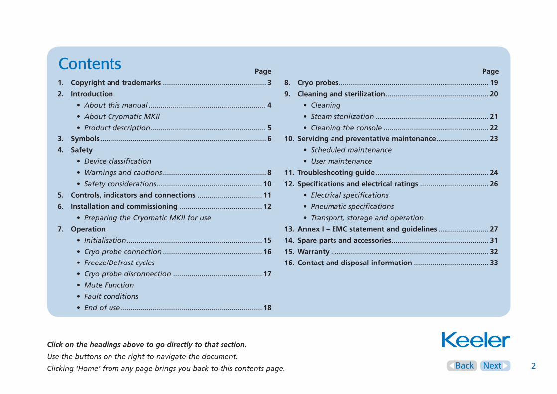
Contents Page
1. Copyrightandtrademarks ................................................... 3
2. Introduction
• Aboutthismanual.......................................................... 4
• AboutCryomaticMKII
• Productdescription......................................................... 5
3. Symbols .................................................................................. 6
4. Safety
• Deviceclassification
• Warningsandcautions ................................................... 8
• Safetyconsiderations .................................................... 10
5. Controls,indicatorsandconnections ................................ 11
6. Installationandcommissioning ......................................... 12
• PreparingtheCryomaticMKIIforuse
7. Operation
• Initialisation ................................................................... 15
• Cryoprobeconnection ................................................. 16
• Freeze/Defrostcycles
• Cryoprobedisconnection ............................................ 17
• MuteFunction
• Faultconditions
• Endofuse ...................................................................... 18
Page
8. Cryoprobes .......................................................................... 19
9. Cleaningandsterilization ................................................... 20
• Cleaning
• Steamsterilization ........................................................ 21
• Cleaningtheconsole .................................................... 22
10. Servicingandpreventativemaintenance .......................... 23
• Scheduledmaintenance
• Usermaintenance
11. Troubleshootingguide ........................................................ 24
12. Specificationsandelectricalratings .................................. 26
• Electricalspecifications
• Pneumaticspecifications
• Transport,storageandoperation
13.AnnexI–EMCstatementandguidelines ......................... 27
14. Sparepartsandaccessories ................................................ 31
15.Warranty .............................................................................. 32
16.Contactanddisposalinformation ..................................... 33
Click on the headings above to go directly to that section.
Usethebuttonsontherighttonavigatethedocument.
Clicking‘Home’fromanypagebringsyoubacktothiscontentspage.

NextHome Back 3
1. Copyright and trademarks
The information contained within this manual must not be reproduced in
whole or in part without the manufacturer’s prior written approval.
As part of our policy for continued product development we reserve the
right to make changes to specifications and other information contained
in this document without prior notice.
Cryomatic MKII is a registered trademark of Keeler Ltd 2013.
Copyright © Keeler Limited 2013.
Published in the UK 2013.

NextHome Back 4
2. Introduction
Thank you for purchasing your Keeler Cryomatic MKII.
We have taken the greatest care in the design, development and
manufacture of this product to ensure that you get many years of
trouble free service. However, it is important that you read the
descriptions, installation and operating instructions carefully prior
to installing or using your new Cryomatic MKII.
About this ManualThis handbook forms the Instructions for Use for the Keeler
Cryomatic MKII, a clinical instrument for cryogenic ophthalmic
surgery.
It contains complete, step-by-step instructions for the
Cryomatic MKII and is intended for use by trained medical
personnel. This manual does not contain clinical instructions or
any recommendations for medical applications. The use of the
Cryomatic MKII in any surgical procedure must always be at the
discretion of a licensed medical practitioner.
Intended useThe Keeler Cryomatic MKII System and probes are for use in
ophthalmic surgery such as cryopexy for retinal detachment, cyclo
destructive procedures in refractory glaucoma, extraction of
fragments within the vitreous cavity, cataract extraction, cryo
destruction of lash follicles for trichiasis and treatment of
retinopathy of prematurity (ROP).
Once the Cryo probe has been correctly positioned the freeze
control is activated and an ice ball is formed around the tip of the
Cryo probe and the adjacent area.
Please read and follow these instructions carefully.

NextHome Back 5
2. Introduction
Product DescriptionThe system comprises a control console and interchangeable Cryo
probes which are connected to the console for use. The re-usable
Cryo probe can be sterilized by autoclaving or other approved
methods. The system requires mains electricity and Nitrous Oxide
or Carbon Dioxide gas to function, this is the responsibility of
the user.
ConsoleThe Cryomatic MKII console is a self contained system. The
console provides the connection point for the Cryo probe,
footswitch, mains electricity, gas supply and scavenging system.
Freeze cycles are controlled by the user operating the footswitch.
When the footswitch is depressed the Cryo probe freezes and
when the footswitch is released the Cryo probe defrosts.
Routine functions, like purging the Cryo probe are performed
automatically when the Cryo probe is connected to the system.
Cryo ProbesDisposable and reusable Cryo probes are connected to the
Cryomatic MKII console via a simple quick release coupling. The
system will not operate until this connection is correctly made.
Each Cryo probe is a complete assembly and no attempt should be
made to dismantle or separate the coupling from the probe.
When the footswitch is pressed, high pressure cryogen gas is
circulated through the Cryo probe, rapid gas expansion in the
probe tip causes freezing according to the Joule-Thompson
principle. The freezing zone of the Cryo probe is limited so that
the iceball propagates at the tip. When the footswitch is released,
an active de-frost is caused by the equalisation of pressure on
either side of the Joule-Thompson nozzle. The gas condenses
releasing its latent heat causing a rapid de-frost.
The Cryo probe assembly is re-usable and as such is fully
autoclaveable according to the procedures outlined in
this manual.
NextHome Back 6
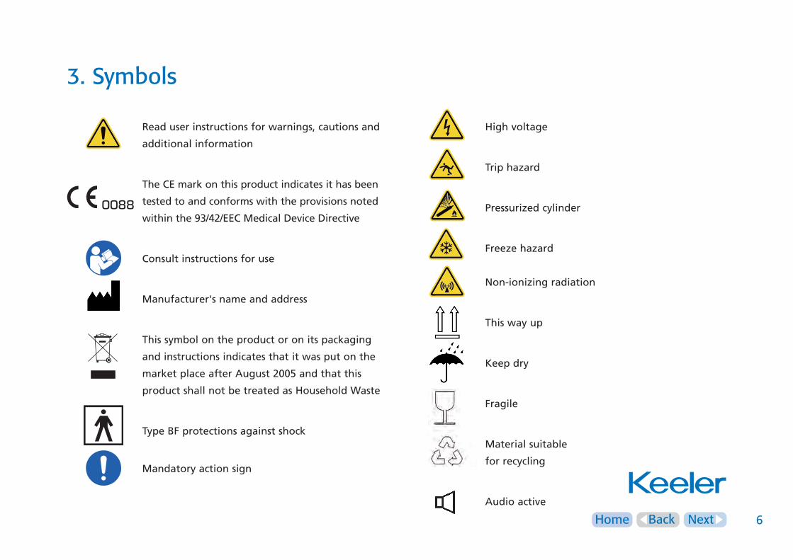
3. Symbols
Read user instructions for warnings, cautions and
additional information
The CE mark on this product indicates it has been
tested to and conforms with the provisions noted
within the 93/42/EEC Medical Device Directive
Consult instructions for use
Manufacturer's name and address
This symbol on the product or on its packaging
and instructions indicates that it was put on the
market place after August 2005 and that this
product shall not be treated as Household Waste
Type BF protections against shock
Mandatory action sign
High voltage
Trip hazard
Pressurized cylinder
Freeze hazard
Non-ionizing radiation
This way up
Keep dry
Fragile
Material suitable
for recycling
Audio active
0088
NextHome Back 7
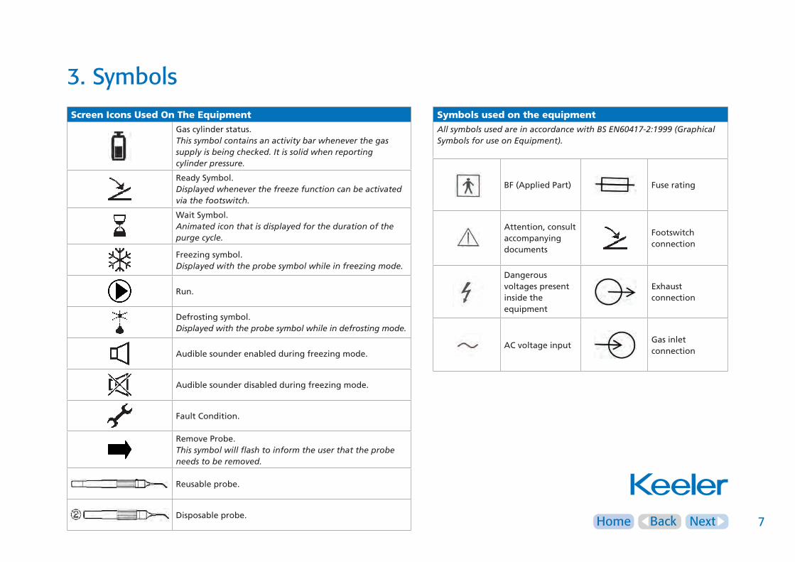
3. SymbolsSymbols used on the equipment
AllsymbolsusedareinaccordancewithBSEN60417-2:1999(GraphicalSymbolsforuseonEquipment).
BF (Applied Part)
Fuse rating
Attention, consult accompanying documents
Footswitch connection
Dangerous voltages present inside the equipment
Exhaust connection
AC voltage input
Gas inlet connection
Screen Icons Used On The Equipment
Gas cylinder status. Thissymbolcontainsanactivitybarwheneverthegassupplyisbeingchecked.Itissolidwhenreportingcylinderpressure.
Ready Symbol. Displayedwheneverthefreezefunctioncanbeactivatedviathefootswitch.
Wait Symbol. Animatediconthatisdisplayedforthedurationofthepurgecycle.
Freezing symbol. Displayedwiththeprobesymbolwhileinfreezingmode.
Run.
Defrosting symbol. Displayedwiththeprobesymbolwhileindefrostingmode.
Audible sounder enabled during freezing mode.
Audible sounder disabled during freezing mode.
Fault Condition.
Remove Probe. Thissymbolwillflashtoinformtheuserthattheprobeneedstoberemoved.
Reusable probe.
Disposable probe.
NextHome Back 8
4. Safety
Device classificationCE Regulation 93/42 EEC: IIb
FDA: II
Carefully read this Instruction Section before using your Keeler
product. For your own safety and that of your customers
observe all cautionary information provided in this section. The
following information is intended to highlight potential safety
hazards that can be associated with misuse, or damage.
Warnings and cautions
Warning
• WARNING: To avoid the risk of electric shock, this equipment
must only be connected to a supply mains with protective earth
• Check your Cryomatic MKII for signs of transport / storage
damage prior to use
• Do not use if the product is visibly damaged, and periodically
inspect for signs of damage
• Do not use in the presence of flammable gases / liquids, or in
an oxygen rich environment
• This product should not be immersed in fluids
Do not fit mains power adapter into a damaged mains
outlet socket
Route power cords safely to eliminate risk of tripping or
damage to equipment
• US Federal law restricts this device to sale by or order of a
physician or practitioner
High pressure gases are present inside unit. Maximum
operating pressure 58 Bar / 650 PSI, maximum cylinder
pressure 83 Bar / 1200 PSI
Observe the usual safety precautions associated with the use of
medical gases, at all times. Copies of these guidelines will be
available from the gas supplier.
Ensure the correct disposition of gas exhausted from the system
so as to minimise the exposure to Nitrous Oxide or Carbon
Dioxide. This is the responsibility of the user.

NextHome Back 9
4. Safety
Caution
• Use only genuine Keeler approved parts and accessories or
device safety and performance may be compromised
• The product has been designed to function safely when at an
ambient temperature between +10°C and +35°C
• Keep out of the reach of children
• To prevent condensation from forming, allow instrument to
come to room temperature before use
• For indoor use only (protect from moisture)
• Keep the console away from sources of liquids and do not
spray with water
• This product is suitable for use with only Nitrous Oxide or
Carbon Dioxide medical gases
• Only non-syphonic gas cylinders should be used with
this device
• No modification of this equipment is allowed
• Care should be taken not to trap fingers in pinch points
during gas bottle change
• Follow guidance on cleaning / routine maintenance to prevent
personal injury / damage to equipment
Switch off the electrical supply and disconnect from the
mains electrical supply before cleaning and inspection
• Do not use hypercarbonate or phenolic based cleaning
solutions or disinfectants containing cationic surfactants (e.g.
Dettox) to clean the console
• Failure to carry out recommended routine maintenance as per
these Instructions for Use may reduce the operational lifetime
of the product
• There are no user serviceable parts inside. Contact authorised
service representative for further information
• At product end of life dispose of in accordance with local
environmental guidelines (WEEE)
NextHome Back 10
4. Safety
Safety considerationsBefore you connect system to the mains socket, carefully read
and understand all the installation instructions in Section 6.
The system has been designed to comply with the following
regulatory standards for Safety and Electromagnetic
Compatibility:
• IEC60601-1, UL60601-1 & CAN/CSA-C22.2 No 601.1
• IEC60601-1-2
Although compliant with applicable EMC standards, this
equipment may still be susceptible to excessive emissions and/or
may interfere with other more sensitive material. This system
should be installed and used following the EMC environment
guidelines contained in section 13 of this manual.
This system should only be used in conjunction with the relevant
accessories and mains leads as supplied by the manufacturer or
distributor. Failure to do this may affect the EMC performance
of the system i.e. increased emissions or reduced immunity.
Relevant accessories are listed in the Spare Parts and
Accessories section.
Ensure the equipment is positioned in such a way that it can
be disconnected from the mains easily.
For your own safety and the safety of the equipment,
always take the following precautions:
• Ensure that the system is inspected by properly trained
personnel once per annum for performance and safety checks
• Inspect the Cryo probe hose and silicone ‘O’ rings for damage
before every use. If there is any sign of damage return to the
manufacturer for servicing prior to use
• Do not try to straighten a bent Cryo tip
• Do not try to re-shape a Cryo tip
• Ensure that the system is clean and dry prior to storage
• Keep this operator manual safe for future reference.
NextHome Back 11
5. Controls, indicators and connections
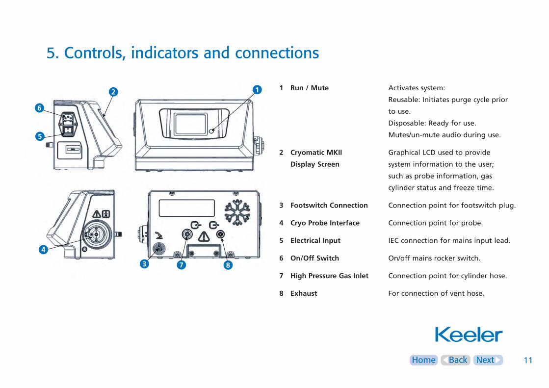
1 Run/Mute Activates system:
Reusable: Initiates purge cycle prior
to use.
Disposable: Ready for use.
Mutes/un-mute audio during use.
2 CryomaticMKII Graphical LCD used to provide
DisplayScreen system information to the user;
such as probe information, gas
cylinder status and freeze time.
3 FootswitchConnection Connection point for footswitch plug.
4 CryoProbeInterface Connection point for probe.
5 ElectricalInput IEC connection for mains input lead.
6 On/OffSwitch On/off mains rocker switch.
7 HighPressureGasInlet Connection point for cylinder hose.
8 Exhaust For connection of vent hose.
12
4
5
6
3 7 8
NextHome Back 12
6. Installation and commissioning
Preparing the Cryomatic MKII for use The Cryomatic MKII consists of the following:
• Cryomatic MKII console
• Footswitch
• Mains cord
• High-pressure gas hose
• Exhaust hose
• Adjustable wrench
• Instructions for use
• 2 spare mains fuses
• Cryo probe(s) must be ordered separately
If any of these parts are missing, contact your distributor
immediately.
Installing Exhaust HoseConnect the exhaust hose provided from the gas exhaust
connection of the console to a scavenging system or suitably
ventilated area (see page 11).
It is the responsibility of the user to ensure the safe disposition
of exhaust gases.
Connecting the FootswitchConnect the footswitch to the appropriate connection point on
the rear of the console noting the alignment of the orientation
key (see page 11).
The footswitch can be disconnected for storage and to facilitate
cleaning. Disconnection is achieved by pulling the collar of the
footswitch connector.
Installing the High Pressure Gas HoseConnect high-pressure hose to the inlet connector (7) at the rear
of the Cryomatic MKII system using the adjustable wrench that
has been provided. Ensure that the coupling is tightened
adequately (see page 13).
Connecting/Changing Gas CylindersGas cylinders must be stored upright, and for a minimum of
eight hours at ambient room temperature prior to use.
Ensure that the gas cylinder is secured properly before use.
Use the following procedure for
connecting or changing gas cylinders:

NextHome Back 13
6. Installation and commissioning
Connection of Cylinder 1 Secure gas cylinder correctly in the upright position.
2 Connect the high pressure hose to the cylinder using the
relevant adaptor.
3 Open cylinder valve slowly (using the adjustable wrench
provided).
4 Any noise of escaping gas indicates that the cylinder has
not been connected correctly – turn off the gas valve
and check connections.
5 Ensure the maximum cylinder pressure does not exceed
1200 PSI/83 Bar.
Keeler recommends fitting a regulator, set below 83bar,
between the cylinder and the Cryomatic MKII console to prevent
overpressure due to temperature variations in the cylinder.
Removal/Disconnection of Cylinders 1 Ensure that cylinder valve is closed.
2 Disconnect the adaptor from the cylinder.
3 Replace cylinder with a fresh one.
The cylinders must be medical grade vapour withdrawal types to
ensure that liquid cryogen is not delivered to the system.
Cryogen gas cylinders used must meet national regulations and
be in accordance with ISO/R 32 and NFPA 99 (USA).
Ensure there is enough gas in the cylinder prior to starting the
procedure. The console cylinder symbol flashes to indicate empty
when the gas supply pressure drops below 450PSI/31Bar (2415
kPa) and the gas cylinder should be replaced at or before this
point. After this the system will continue to function in the
usual way, however freeze performance will be reduced.
Information regarding the correct storage and handling of gas
cylinders should be obtained from the gas supplier.

NextHome Back 14
6. Installation and commissioning
Electrical SupplyThe Cryomatic MKII system requires connection to a mains
electrical supply for operation.
Only a hospital grade 3-conductor electrical power
supply cable must be used.
For USA and Canada: Detachable power supply cord set, UL
listed, type SJE, SJT or SJO, 3-conductor, not smaller than 18
AWG. Plug, cable and ground lead connection of the socket
have to be in perfect condition.
AtthisstagetheprobeshouldNOTbeconnected.
1 Connect the system to a suitable mains supply using the
mains cord that has been supplied.
2 Switch on power via the rocker switch at the side of the
system.
3 The cylinder symbol is activated while the
Cryomatic MKII system prepares itself and Mute symbol
will displayed on the screen.
NextHome Back 15
7. Operation
These instructions cover day-to-day operation of the system.
Other operations, such as maintenance and repair, should only
be carried out by fully trained personnel who are employed by,
or authorized by, the supplier.
InitialisationBefore using the Cryomatic MKII system, make sure it has been
correctly installed in accordance with Section 6.
AtthisstagetheprobemustNOTbeconnected.Ifaprobehas
beenconnectedaflasharrowwillappearindicatingthatthe
probemustberemoved.
1 Ensure that the equipment is switched on using the
mains inlet rocker switch.
2 An activity bar within the Cylinder Symbol indicates that
the gas supply is being checked.
If a warning is displayed, refer to troubleshooting in
Section 11.
3 When the initialisation checks are complete verify that
there is adequate cryogen gas supply - this is indicated
by the Cylinder Symbol on the front panel display. The
Cylinder Symbol will flash if the cylinder pressure drops
below a viable level (450PSI).
4 The equipment is now at REST. The Cryo Probe can
now be connected.
The collar will move in a clockwise direction indicating that the
probe is correctly locked. When the probe is properly connected
the relevant Probe Symbol is displayed together with the
Accept option.

NextHome Back 16
7. Operation
Cryo Probe ConnectionObserve sterilization protocol before using a Cryo probe (see
section 9). Allow Cryo probe to cool to room temperature after
a sterilization.
Before connecting the Cryo probe inspect it for signs of
obvious damage.
1 Remove sterilisation cap from the probe.
2 Connect the Cryo probe to the console by inserting it
into the coupling and pushing against the spring
operated collar until a positive click is heard. When the
probe is properly connected the relevant Probe Symbol is
displayed together with the Run option.
3 To proceed, the Run button must be pushed.
4 If a reusableprobe has been connected, the system
automatically initiates a purging cycle of 90 seconds.
During the purge cycle an animated Wait Symbol is
displayed alongside the Probe Symbol. Three short beeps
signal that the purge cycle is complete.
5 The equipment is now ready for use as indicated by the
timer and the Ready Symbol.
6 If a disposable probe has been connected, there is no
purge cycle.
While the probe is purging all footswitch operations are
disallowed to ensure that the Cryo probe has completed the
minimum purge.
NextHome Back 17
7. Operation
WARNING: Probe tip reaches extremely low temperature
in use.
Freeze/Defrost CyclesFreezing of the Cryo probe is controlled manually by the
operator using the footswitch.
1 Press the footswitch down. Freezing starts immediately
and the digital timer will increment.
2 An audible warning sounds every second during the
freeze cycle and the Freezing Symbol is displayed.
3 De-frosting is achieved by releasing the footswitch. The
timer will stop counting and the Defrosting Symbol is
displayed.
4 Subsequent freeze cycles can be carried out by simply
repeating steps 1-4 as soon as the Ready Symbol is
displayed.
The freezing function is often accompanied by a characteristic
‘pulsing’ sound which indicates that the Cryomatic MKII is
regulating the gas to the optimum pressure for the probe.
The ‘pulsing’ may vary or cease completely depending on the
pressure of gas in the cylinder.
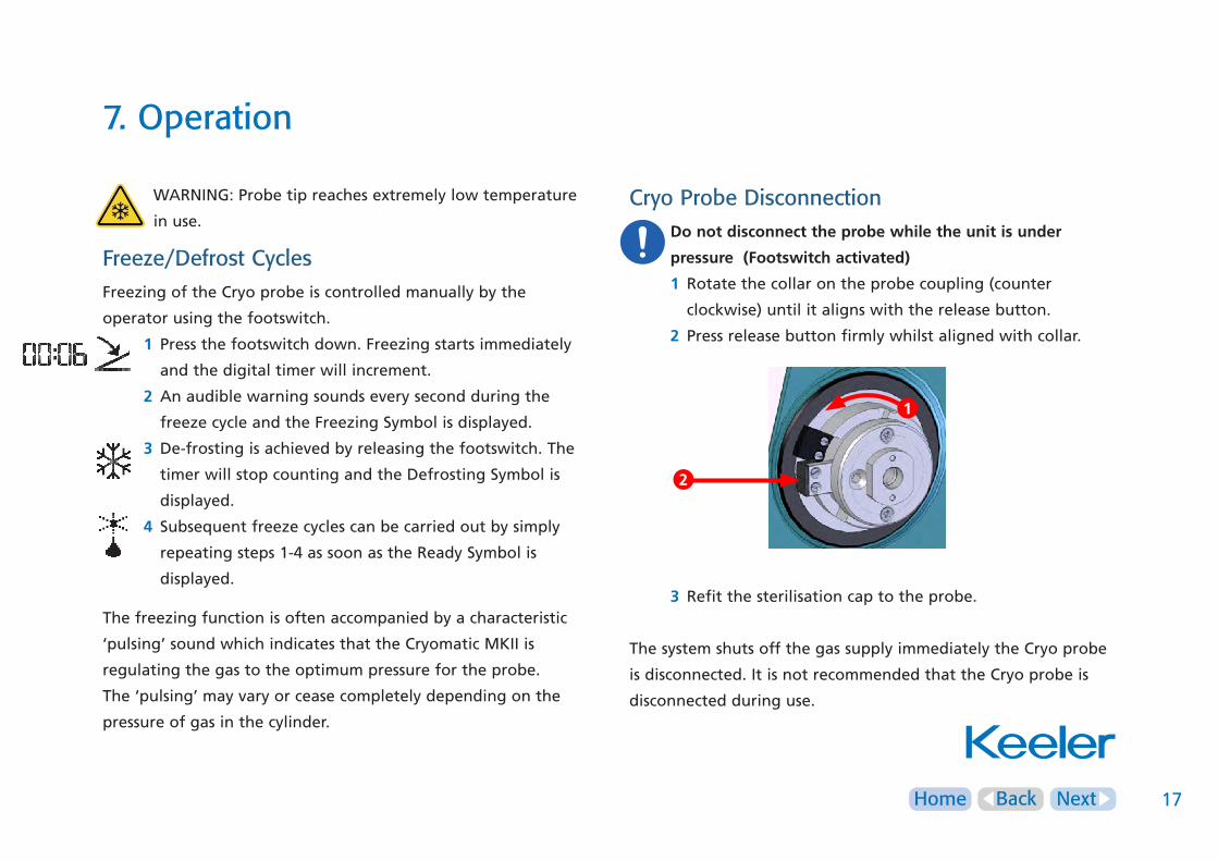
Cryo Probe Disconnection Donotdisconnecttheprobewhiletheunitisunder
pressure(Footswitchactivated)
1 Rotate the collar on the probe coupling (counter
clockwise) until it aligns with the release button.
2 Press release button firmly whilst aligned with collar.
3 Refit the sterilisation cap to the probe.
The system shuts off the gas supply immediately the Cryo probe
is disconnected. It is not recommended that the Cryo probe is
disconnected during use.
2
1
NextHome Back 18
7. Operation
Mute Function The audible indicator is normally active during freeze and
purge cycles as indicated on the LCD screen.
It can be muted by pressing the key adjacent
to the symbol. The symbol is changed accordingly.
The indicator can be reactivated by pressing the
key again (see Section 5 [1]).
Fault Conditions The Cryomatic MKII system has the ability to detect a
range of system faults. In the unlikely event of a fault
condition arising, the fault symbol icon will flash and a
short error message will be displayed. Refer to section 11
for troubleshooting.
Contact distributor or manufacturer for assistance.
Caution
In the event of power interruption during use the device valves
fail safely closed.
End of Use Ensure that the following procedures are carried out at the end
of the current usage:
1 Close the cylinder valve.
2 Switch off the electrical supply.
3 Ensure that the mains cord, footswitch and the Cryo
probes are stored properly to avoid accidental damage.
NextHome Back 19
8. Cryo probes
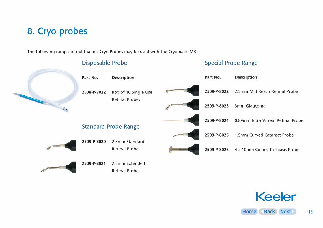
The following ranges of ophthalmic Cryo Probes may be used with the Cryomatic MKII.
Disposable Probe
PartNo. Description
2508-P-7022 Box of 10 Single Use
Retinal Probes
Standard Probe Range
2509-P-8020 2.5mm Standard
Retinal Probe
2509-P-8021 2.5mm Extended
Retinal Probe
Special Probe Range
PartNo. Description
2509-P-8022 2.5mm Mid Reach Retinal Probe
2509-P-8023 3mm Glaucoma
2509-P-8024 0.89mm Intra Vitreal Retinal Probe
2509-P-8025 1.5mm Curved Cataract Probe
2509-P-8026 4 x 10mm Collins Trichiasis Probe
NextHome Back 20
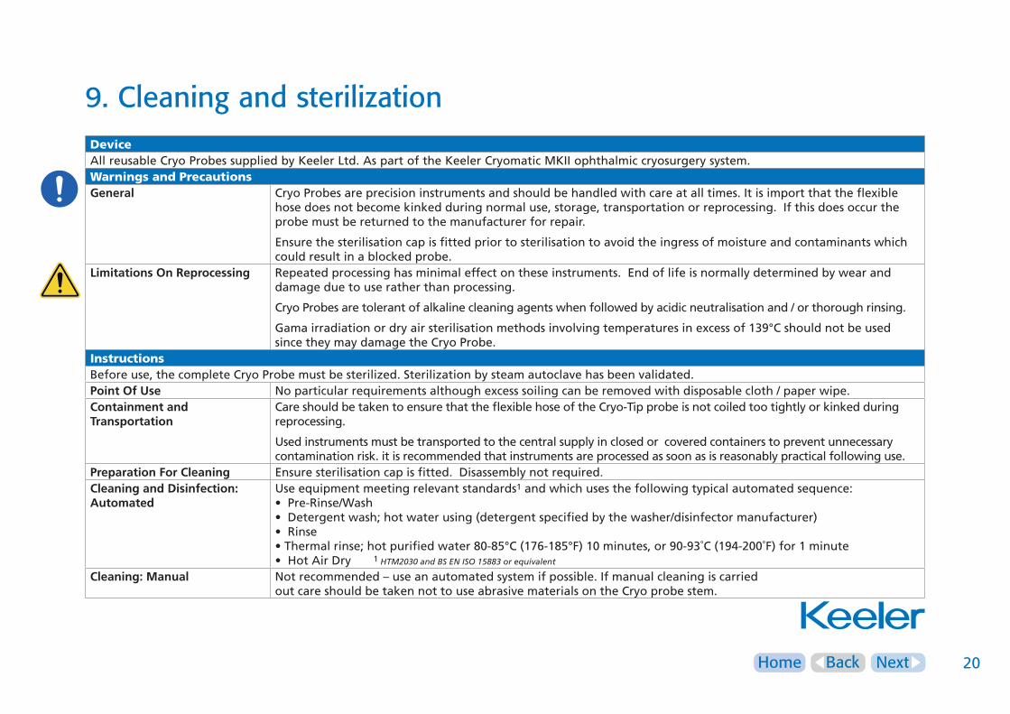
9. Cleaning and sterilizationDeviceAll reusable Cryo Probes supplied by Keeler Ltd. As part of the Keeler Cryomatic MKII ophthalmic cryosurgery system.Warnings and PrecautionsGeneral Cryo Probes are precision instruments and should be handled with care at all times. It is import that the flexible
hose does not become kinked during normal use, storage, transportation or reprocessing. If this does occur the probe must be returned to the manufacturer for repair.
Ensure the sterilisation cap is fitted prior to sterilisation to avoid the ingress of moisture and contaminants which could result in a blocked probe.
LimitationsOnReprocessing Repeated processing has minimal effect on these instruments. End of life is normally determined by wear and damage due to use rather than processing.
Cryo Probes are tolerant of alkaline cleaning agents when followed by acidic neutralisation and / or thorough rinsing.
Gama irradiation or dry air sterilisation methods involving temperatures in excess of 139°C should not be used since they may damage the Cryo Probe.
InstructionsBefore use, the complete Cryo Probe must be sterilized. Sterilization by steam autoclave has been validated.PointOfUse No particular requirements although excess soiling can be removed with disposable cloth / paper wipe.ContainmentandTransportation
Care should be taken to ensure that the flexible hose of the Cryo-Tip probe is not coiled too tightly or kinked during reprocessing.
Used instruments must be transported to the central supply in closed or covered containers to prevent unnecessary contamination risk. it is recommended that instruments are processed as soon as is reasonably practical following use.
PreparationForCleaning Ensure sterilisation cap is fitted. Disassembly not required.CleaningandDisinfection:Automated
Use equipment meeting relevant standards1 and which uses the following typical automated sequence:• Pre-Rinse/Wash• Detergent wash; hot water using (detergent specified by the washer/disinfector manufacturer)• Rinse• Thermal rinse; hot purified water 80-85°C (176-185°F) 10 minutes, or 90-93˚C (194-200˚F) for 1 minute• Hot Air Dry 1 HTM2030andBSENISO15883orequivalent
Cleaning:Manual Not recommended – use an automated system if possible. If manual cleaning is carried out care should be taken not to use abrasive materials on the Cryo probe stem.
NextHome Back 21
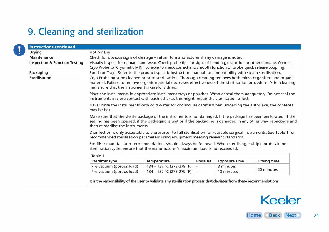
9. Cleaning and sterilizationInstructions continuedDrying Hot Air DryMaintenance Check for obvious signs of damage – return to manufacturer if any damage is noted.Inspection&FunctionTesting Visually inspect for damage and wear. Check probe tips for signs of bending, distortion or other damage. Connect
Cryo Probe to ‘Cryomatic MKII’ console to check correct and smooth function of probe quick release coupling.Packaging Pouch or Tray - Refer to the product-specific instruction manual for compatibility with steam sterilisation.Sterilisation Cryo Probe must be cleaned prior to sterilisation. Thorough cleaning removes both micro-organisms and organic
material. Failure to remove organic material decreases effectiveness of the sterilisation procedure. After cleaning, make sure that the instrument is carefully dried.
Place the instruments in appropriate instrument trays or pouches. Wrap or seal them adequately. Do not seal the instruments in close contact with each other as this might impair the sterilisation effect.
Never rinse the instruments with cold water for cooling. Be careful when unloading the autoclave, the contents may be hot.
Make sure that the sterile package of the instruments is not damaged. If the package has been perforated, if the sealing has been opened, if the packaging is wet or if the packaging is damaged in any other way, repackage and then re-sterilise the instruments.
Disinfection is only acceptable as a precursor to full sterilisation for reusable surgical instruments. See Table 1 for recommended sterilisation parameters using equipment meeting relevant standards.
Steriliser manufacturer recommendations should always be followed. When sterilising multiple probes in one sterilisation cycle, ensure that the manufacturer's maximum load is not exceeded.
Itistheresponsibilityoftheusertovalidateanysterilisationprocessthatdeviatesfromtheserecommendations.
Table1Sterilizertype Temperature Pressure Exposuretime DryingtimePre-vacuum (porous load) 134 – 137 °C (273-279 °F) - 3 minutes
20 minutesPre-vacuum (porous load) 134 – 137 °C (273-279 °F) - 18 minutes
NextHome Back 22
9. Cleaning and sterilizationInstructions continued
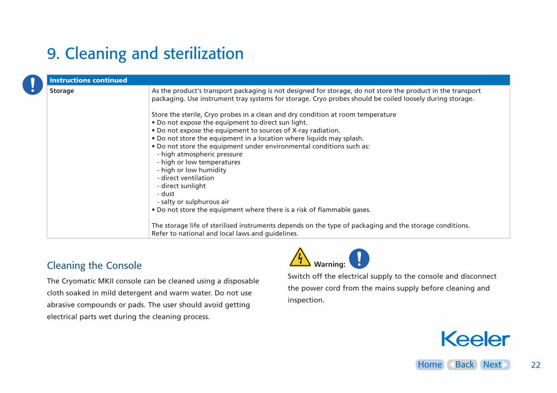
Storage As the product's transport packaging is not designed for storage, do not store the product in the transport packaging. Use instrument tray systems for storage. Cryo probes should be coiled loosely during storage. Store the sterile, Cryo probes in a clean and dry condition at room temperature• Do not expose the equipment to direct sun light.• Do not expose the equipment to sources of X-ray radiation.• Do not store the equipment in a location where liquids may splash.• Do not store the equipment under environmental conditions such as: - high atmospheric pressure - high or low temperatures - high or low humidity - direct ventilation - direct sunlight - dust - salty or sulphurous air• Do not store the equipment where there is a risk of flammable gases. The storage life of sterilised instruments depends on the type of packaging and the storage conditions.Refer to national and local laws and guidelines.
Cleaning the ConsoleThe Cryomatic MKII console can be cleaned using a disposable
cloth soaked in mild detergent and warm water. Do not use
abrasive compounds or pads. The user should avoid getting
electrical parts wet during the cleaning process.
Warning:
Switch off the electrical supply to the console and disconnect
the power cord from the mains supply before cleaning and
inspection.

NextHome Back 23
10. Servicing and preventative maintenance
Scheduled MaintenanceThe Cryomatic MKII console and probes should be inspected
annually by Keeler trained personnel. This service will include
performance checks, cleaning or replacement of inlet filters and
safety checks on pneumatic couplings.
User Maintenance - Console There are no user serviceable parts in the Cryomatic MKII
console, operator maintenance is restricted to cleaning the
console surface.
User Maintenance - Reusable probesa Cleaning the Cryo probe tip.
b Inspecting the Cryo probes for signs of damage before every
use.
c Damaged or missing ‘O’ ring seal should be replaced before
sterilisation and use.
Only Keeler specified parts should be used. See spares
Section 14.
d Inspecting the footswitch and cord for signs of damage before
each use.
e Inspecting the mains cord for signs of damage before each use.
f Inspecting the high pressure hose and exhaust hose for signs
of damage before each use.
All repairs should be carried out only by Keeler trained
personnel or their representatives.
Keeler will make available on request circuit diagrams,
component part lists, descriptions, calibration instructions, or
other information that will assist SERVICE PERSONNEL to repair
those parts of ME EQUIPMENT that are designated as repairable
by SERVICE PERSONNEL.
Potentially dangerous voltages are present inside the
equipment – under no circumstances should the covers be
removed.
’O’ringshouldbefittedasshown
NextHome Back 24
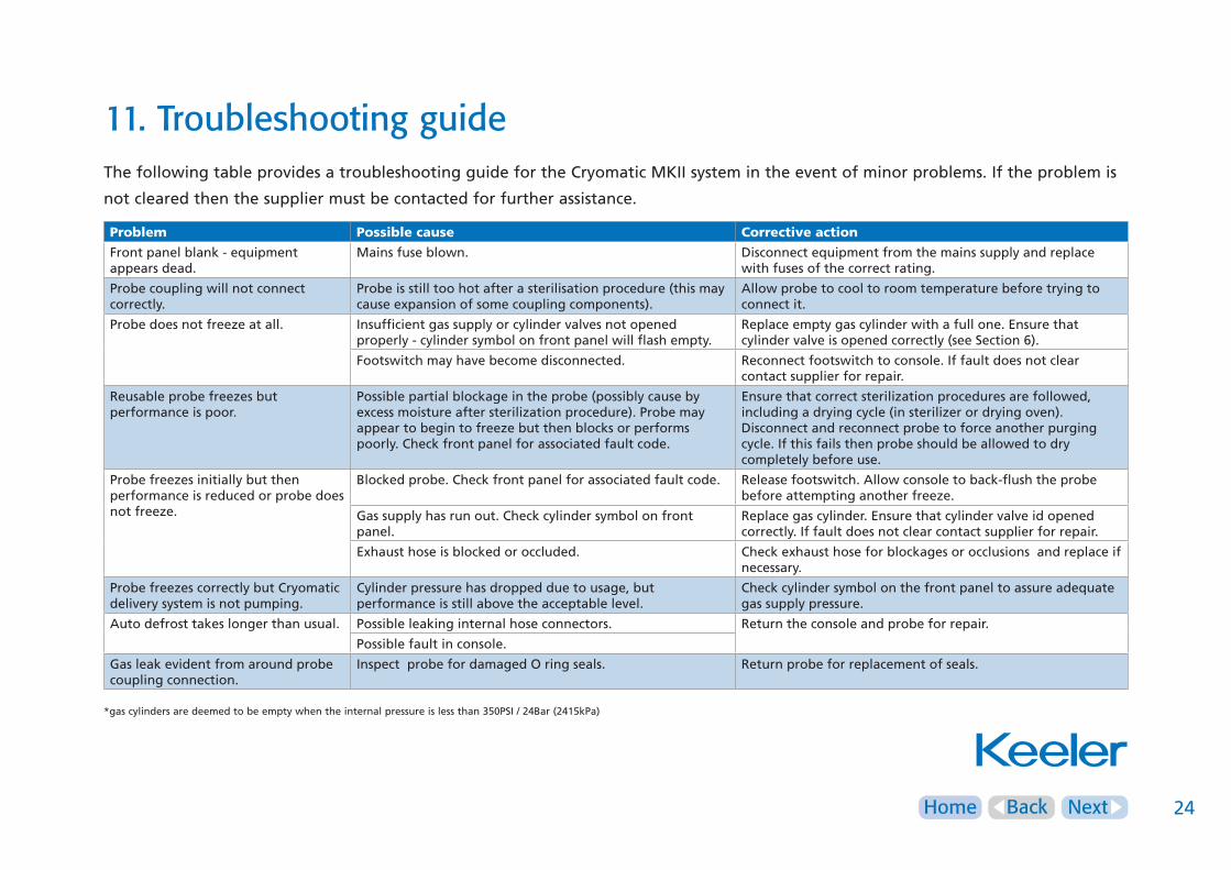
11. Troubleshooting guideThe following table provides a troubleshooting guide for the Cryomatic MKII system in the event of minor problems. If the problem is
not cleared then the supplier must be contacted for further assistance.
Problem Possible cause Corrective action
Front panel blank - equipment appears dead.
Mains fuse blown. Disconnect equipment from the mains supply and replace with fuses of the correct rating.
Probe coupling will not connect correctly.
Probe is still too hot after a sterilisation procedure (this may cause expansion of some coupling components).
Allow probe to cool to room temperature before trying to connect it.
Probe does not freeze at all. Insufficient gas supply or cylinder valves not opened properly - cylinder symbol on front panel will flash empty.
Replace empty gas cylinder with a full one. Ensure that cylinder valve is opened correctly (see Section 6).
Footswitch may have become disconnected. Reconnect footswitch to console. If fault does not clear contact supplier for repair.
Reusable probe freezes but performance is poor.
Possible partial blockage in the probe (possibly cause by excess moisture after sterilization procedure). Probe may appear to begin to freeze but then blocks or performs poorly. Check front panel for associated fault code.
Ensure that correct sterilization procedures are followed, including a drying cycle (in sterilizer or drying oven). Disconnect and reconnect probe to force another purging cycle. If this fails then probe should be allowed to dry completely before use.
Probe freezes initially but then performance is reduced or probe does not freeze.
Blocked probe. Check front panel for associated fault code. Release footswitch. Allow console to back-flush the probe before attempting another freeze.
Gas supply has run out. Check cylinder symbol on front panel.
Replace gas cylinder. Ensure that cylinder valve id opened correctly. If fault does not clear contact supplier for repair.
Exhaust hose is blocked or occluded. Check exhaust hose for blockages or occlusions and replace if necessary.
Probe freezes correctly but Cryomatic delivery system is not pumping.
Cylinder pressure has dropped due to usage, but performance is still above the acceptable level.
Check cylinder symbol on the front panel to assure adequate gas supply pressure.
Auto defrost takes longer than usual. Possible leaking internal hose connectors. Return the console and probe for repair.
Possible fault in console.
Gas leak evident from around probe coupling connection.
Inspect probe for damaged O ring seals. Return probe for replacement of seals.
*gas cylinders are deemed to be empty when the internal pressure is less than 350PSI / 24Bar (2415kPa)
NextHome Back 25
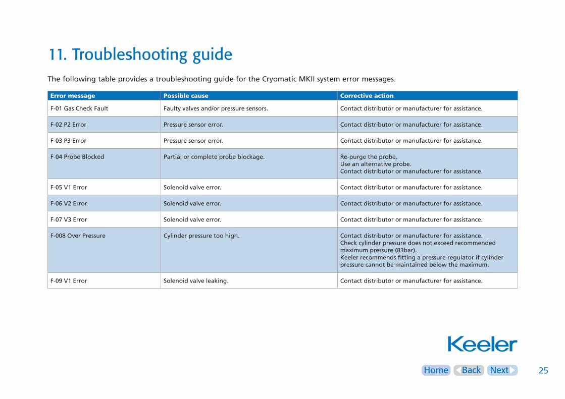
11. Troubleshooting guideThe following table provides a troubleshooting guide for the Cryomatic MKII system error messages.
Error message Possible cause Corrective action
F-01 Gas Check Fault Faulty valves and/or pressure sensors. Contact distributor or manufacturer for assistance.
F-02 P2 Error Pressure sensor error. Contact distributor or manufacturer for assistance.
F-03 P3 Error Pressure sensor error. Contact distributor or manufacturer for assistance.
F-04 Probe Blocked Partial or complete probe blockage. Re-purge the probe.Use an alternative probe.Contact distributor or manufacturer for assistance.
F-05 V1 Error Solenoid valve error. Contact distributor or manufacturer for assistance.
F-06 V2 Error Solenoid valve error. Contact distributor or manufacturer for assistance.
F-07 V3 Error Solenoid valve error. Contact distributor or manufacturer for assistance.
F-008 Over Pressure Cylinder pressure too high. Contact distributor or manufacturer for assistance.Check cylinder pressure does not exceed recommended maximum pressure (83bar).Keeler recommends fitting a pressure regulator if cylinder pressure cannot be maintained below the maximum.
F-09 V1 Error Solenoid valve leaking. Contact distributor or manufacturer for assistance.
NextHome Back 26
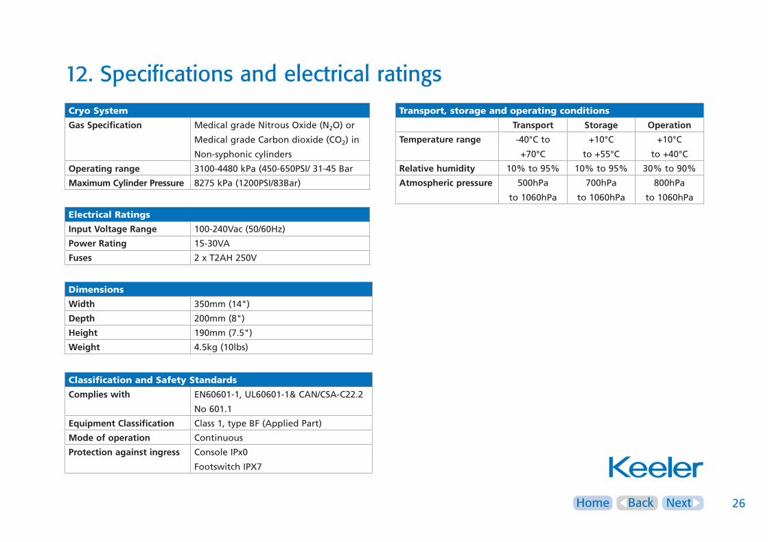
12. Specifications and electrical ratingsCryo System
GasSpecification Medical grade Nitrous Oxide (N2O) or
Medical grade Carbon dioxide (CO2) in
Non-syphonic cylinders
Operatingrange 3100-4480 kPa (450-650PSI/ 31-45 Bar
MaximumCylinderPressure 8275 kPa (1200PSI/83Bar)
Transport, storage and operating conditions
Transport Storage Operation
Temperaturerange -40°C to
+70°C
+10°C
to +55°C
+10°C
to +40°C
Relativehumidity 10% to 95% 10% to 95% 30% to 90%
Atmosphericpressure 500hPa
to 1060hPa
700hPa
to 1060hPa
800hPa
to 1060hPa
Dimensions
Width 350mm (14")
Depth 200mm (8")
Height 190mm (7.5")
Weight 4.5kg (10lbs)
Classification and Safety Standards
Complieswith EN60601-1, UL60601-1& CAN/CSA-C22.2
No 601.1
EquipmentClassification Class 1, type BF (Applied Part)
Modeofoperation Continuous
Protectionagainstingress Console IPx0
Footswitch IPX7
Electrical Ratings
InputVoltageRange 100-240Vac (50/60Hz)
PowerRating 15-30VA
Fuses 2 x T2AH 250V
NextHome Back 27
13. Annex I – EMC statement and guidelines
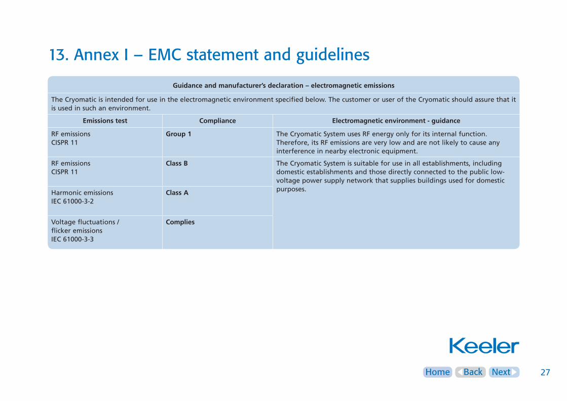
Guidanceandmanufacturer’sdeclaration–electromagneticemissions
The Cryomatic is intended for use in the electromagnetic environment specified below. The customer or user of the Cryomatic should assure that it is used in such an environment.
Emissionstest Compliance Electromagneticenvironment-guidance
RF emissions CISPR 11
Group1 The Cryomatic System uses RF energy only for its internal function. Therefore, its RF emissions are very low and are not likely to cause any interference in nearby electronic equipment.
RF emissions CISPR 11
ClassB The Cryomatic System is suitable for use in all establishments, including domestic establishments and those directly connected to the public low-voltage power supply network that supplies buildings used for domestic purposes.Harmonic emissions
IEC 61000-3-2ClassA
Voltage fluctuations /flicker emissionsIEC 61000-3-3
Complies

NextHome Back 28
13. Annex I – EMC statement and guidelines
Guidanceandmanufacturer’sdeclaration–electromagneticimmunity
The Cryomatic is intended for use in the electromagnetic environment specified below. The customer or the user should assure that it is used in such an environment.
Immunitytest IEC60601Testlevel Compliancelevel Electromagneticenvironment-guidance
Electrostaticdischarge (ESD).IEC 61000-4-2
± 6 kV contact± 8 kV air
± 6 kV contact± 8 kV air
Floors should be wood, concrete or ceramic tile.If floors are covered with synthetic material, the relative humidity should be at least 30%.
Electrical fasttransient/burst.IEC 61000-4-4
± 2 kV for power supply lines± 1 kV for input/output lines
± 2 kV for power supply lines± 1 kV for input/output lines
Mains power quality should be that of a typical commercial or hospital environment.
Surge.IEC 61000-4-5
± 1 kV line(s) to line(s)± 2 kV line(s) to earth
± 1 kV line(s) to line(s)N/A
Mains power quality should be that of a typical commercial or hospital environment.
Voltage dips, shortinterruptions andvoltage variations onpower supply inputlines.IEC 61000-4-11
<5% UT
(> 95% dip in UT) for 0.5 cycles
40% UT
(60% dip in UT ) for 5 cycles
70% UT (30% dip in UT ) for 25 cycles
<5% UT
(>95% dip in UT) for 5 sec
<5% UT
(> 95% dip in UT) for 0.5 cycles
40% UT
(60% dip in UT ) for 5 cycles
70% UT (30% dip in UT ) for 25 cycles
<5% UT
(>95% dip in UT) for 5 s
Mains power quality should be that of a typical commercial or hospital environment.
If the user of the Cryomatic requires continued operation during power mains interruptions, it is recommended that the instrument be powered from an uninterruptible power supply or battery.
Power frequency(50/60 Hz) magneticfield. IEC 61000-4-8
3 A/m 3 A/m Power frequency magnetic fields should be at levels characteristic of a typical location in a typical commercial or hospital environment.
Note UT is the a.c. mains voltage prior to application of the test level.

NextHome Back 29
13. Annex I – EMC statement and guidelines
Guidanceandmanufacturer’sdeclaration–electromagneticimmunity
The Cryomatic is intended for use in the electromagnetic environment specified below. The customer or user should assure that it is used in such an environment.
Immunitytest IEC60601Testlevel Compliancelevel Electromagneticenvironment-guidance
Conducted RF IEC 61000-4-6
Radiated RFIEC 61000-4-3
3 Vrms150 kHz to 80 MHz
3 V/m80MHz to 2.5GHz
3 Vrms
3 V/m
Portable and mobile RF communications equipment should be used no closer to any part of the Cryomatic, including cables, than the recommended separation distances calculated from the equation applicable to the frequency of the transmitter.
Recommendedseparationdistanced = 1.2 √ p
d = 1.2 √ p 80MHz to 800 MHzd = 2.3 √ p 800MHz to 2.5GHz
Where p is the maximum output power rating of the transmitter in watts (W) according to the transmitter manufacturer and d is the recommended separation distance in metres(m).
Field strengths from fixed RF transmitters, as determined by an electromagnetic site surveya, should be less than the compliance level in each frequency range.b
Interference may occur in the vicinity of equipment marked with the following symbol:
Note1 At 80MHz and 800MHz, the higher frequency range applies.Note2 These guidelines may not apply in all situations. Electromagnetic propagation is affected by absorption and reflection from structures, objects and people.a Field strengths from fixed transmitters, such as base stations (cellular/cordless) telephones and land mobile radios, amateur radio, AM and FM radio broadcast and TV broadcast cannot be predicted theoretically with accuracy. To assess the electromagnetic environment due to fixed RF transmitters, an electromagnetic site survey should be considered. If the measured field strength in the location in which the Cryomatic is used exceeds the applicable RF compliance level above, the Cryomatic should be observed to verify normal operation. If abnormal performance is observed, additional measures may be necessary, such as re-orientating or relocating the Cryomatic.b Over the frequency range 150kHz to 80 MHz, field strengths should be less than 3 V/m.

NextHome Back 30
13. Annex I – EMC statement and guidelines
RecommendedseparationdistancesbetweenportableandmobileRFcommunicationsequipmentandtheCryomatic
The Cryomatic is intended for the use in an electromagnetic environment in which radiated RF disturbances are controlled. The customer or the user of the Cryomatic can help prevent electromagnetic interference by maintaining a minimum distance between portable and mobile RF communications equipment (transmitters) and the Cryomatic as recommended below, according to the maximum output power of the communications equipment.
Ratedmaximumoutputpowerof
transmitterW
Separationdistanceaccordingtofrequencyoftransmitterm
150 kHz to 80MHzd = 1.2√ p
80MHz to 800MHzd = 1.2√ p
800MHz to 2.5GHzd = 2.3√ p
0.01 0.12 0.12 0.23
0.1 0.38 0.38 0.73
1 1.2 1.2 2.3
10 3.8 3.8 7.3
100 12 12 23
For transmitters rated at a maximum output power not listed above, the recommended separation distance d in metres (m) can be estimated using the equation applicable to the frequency of the transmitter, where p is the maximum output power rating of the transmitter in watts (W) according to the transmitter manufacturer.
Note1 At 80MHz and 800MHz, the higher frequency range applies.Note2 These guide lines may not apply in all situations. Electromagnetic propagation is affected by absorption and reflection from structures, objects and people.
TheCryomaticshouldnotbeusedadjacenttoorstackedwithanyotherequipment.Ifthisconfigurationisrequired,thennormaloperationoftheCryomaticshouldbeverifiedinthissetting.
NextHome Back 31
14. Spare parts and accessories
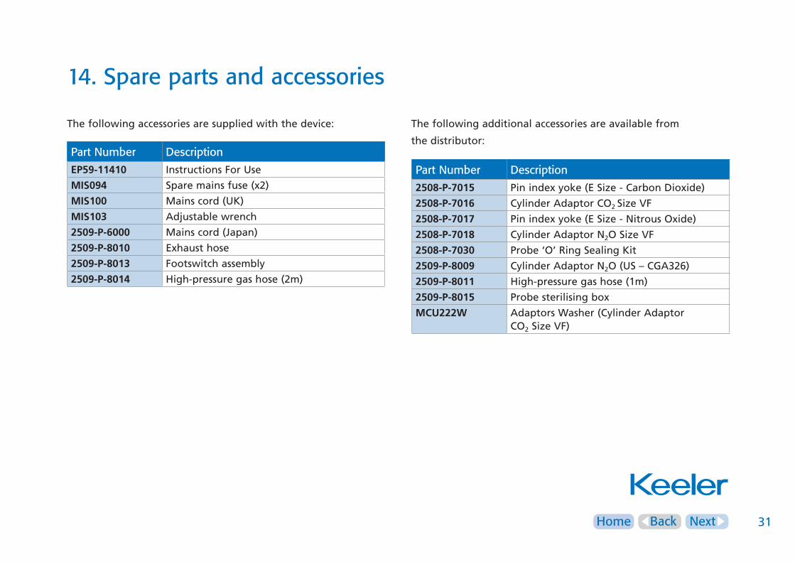
The following accessories are supplied with the device: The following additional accessories are available from
the distributor:Part Number Description
EP59-11410 Instructions For Use
MIS094 Spare mains fuse (x2)
MIS100 Mains cord (UK)
MIS103 Adjustable wrench
2509-P-6000 Mains cord (Japan)
2509-P-8010 Exhaust hose
2509-P-8013 Footswitch assembly
2509-P-8014 High-pressure gas hose (2m)
Part Number Description
2508-P-7015 Pin index yoke (E Size - Carbon Dioxide)
2508-P-7016 Cylinder Adaptor CO2 Size VF
2508-P-7017 Pin index yoke (E Size - Nitrous Oxide)
2508-P-7018 Cylinder Adaptor N2O Size VF
2508-P-7030 Probe ‘O’ Ring Sealing Kit
2509-P-8009 Cylinder Adaptor N2O (US – CGA326)
2509-P-8011 High-pressure gas hose (1m)
2509-P-8015 Probe sterilising box
MCU222W Adaptors Washer (Cylinder AdaptorCO2 Size VF)

NextHome Back 32
15. Warranty
TheCryomaticMKIIanditscomponentsarecoveredbywarranty
thattheymeettheirperformancestandardsandarefreefrom
anydefectsinmaterialsorworkmanship.Within24monthsfrom
deliverybyKeeler,themanufacturershallatnochargetothe
customer,uponwrittennoticefromthecustomer,repairor
replaceanycomponentswhicharedefectiveinmaterialor
workmanship.
Thecustomeragreesthatitshallhavenoremedyintheeventof
anybreachoftheforegoingwarrantyotherthanasprovided
above.Thiswarrantyisexclusiveandinlieuofallother
warranties,expressedorimplied,andallimpliedwarrantiesof
merchantabilityorfitnessforaparticularpurposeareexpressly
disclaimed.
Theobligationsofthemanufacturerassetforthinthiswarranty
areexpresslyconditionaluponthefollowing:-
(i) No alterations or repairs of any malfunction of the system shall
be made to the system except by the manufacturer or his
authorized representative, without the prior written approval of
the manufacturer or his authorized representative (and in no case
will the manufacturer assume responsibility for repairs or
alterations made by those other than the manufacturer or his
authorized representative).
And
(ii) The customer shall give notice to the manufacturer or their
authorized representative of any malfunction of the system and
shall not use the system in any surgical operation after they are
aware of any malfunction.
(iii) The customer complies with manufacturer’s recommended
Preventative Maintenance (see Section 10) and can provide proof
of such action.

Home Back 33Home Back
16. Contact, packaging and disposal information
ManufacturerKeeler Limited Clewer Hill RoadWindsorBerkshireSL4 4AA
Freephone 0800 521251Tel +44 (0) 1753 857177Fax +44 (0) 1753 827145
USA Sales OfficeKeeler USA456 ParkwayBroomallPA 19008USA
Toll Free 1 800 523 5620Tel 1 610 353 4350Fax 1 610 353 7814
India OfficeKeeler India Halmer India Pvt. Ltd.B1-401, Boomerang, ChandivaliAndheri (East) Mumbai - 400072India
Tel +91 (22) 6708 0405Fax +91 (99303) 11090
China OfficeKeeler China1012BKunTai International Mansion12B ChaoWai St.Chao Yang DistrictBeijing, 10020China
Tel +86 (10) 51261868Fax +86 (10) 58790155
Disposal of old electrical and electrical equipment(Applicable in the European Union and other European Countries with separate Collection Systems).
This symbol on the Product or on its Packaging and instructions indicates it was put on the market place after August 2005 and this product shall not be treated as Household Waste.
To reduce the environmental impact of WEEE (Waste Electrical Electronic Equipment) and minimise the volume of WEEE entering landfills we encourage at product end of life that this Equipment is recycled and reused.
If you need more information on the collection, reuse and recycling then please contact B2B compliance on 01691 676124 (+44 1691 676124). (UK only).
CRYOMKIIIFUEN.DM.220713v1