keeping it together: interleaved kirigami extension assembly
TRANSCRIPT

Keeping It Together: Interleaved Kirigami Extension Assembly
Xinyu Wang,1,2 Simon D. Guest ,3 and Randall D. Kamien 2
1School of Civil Engineering, Southeast University, Nanjing, 210096, China2Department of Physics and Astronomy, University of Pennsylvania,
Philadelphia, Pennsylvania 19104, USA3Department of Engineering, University of Cambridge,
Trumpington Street, Cambridge CB2 1PZ, United Kingdom
(Received 27 February 2019; revised manuscript received 30 October 2019; published 21 January 2020)
Traditional origami structures can be continuously deformed back to a flat sheet of paper, whiletraditional kirigami requires glue or seams in order to maintain its rigidity. In the former, nontrivialgeometry can be created through overfolding paper, while in the latter, the paper topology is modified. Herewe propose a hybrid approach that relies on overlapped flaps that create in-plane compression resulting inthe formation of polyhedra composed of freely supported plates. Not only are these structures self-locking,but they have colossal load-to-weight ratios of order 104.
DOI: 10.1103/PhysRevX.10.011013 Subject Areas: Mechanics, Metamaterials
I. INTRODUCTION
The role of self-folding and unfolding has become evermore used as a framework to understand natural structure[1,2]. Since the tunability of geometry is scale invariant,origami- and kirigami-inspired structures translate fromlarge to small scales as can be seen from the packagingmaterials in daily life [3] to deployable solar panels forspace missions [4,5]. Moreover, their transformabilityserves as a powerful tool to program shape-inducedproperties: these architected structures have been utilizedin flexible electronics [6], mechanical metamaterials [7–9],and soft robots [10,11].In practice, origami and kirigami start with geometric
design. However, paper, time, and human effort are allrequired in order to design origami structures with exqui-sitely detailed Gaussian curvature [12]. Recently, kirigamimethods have been developed that allow, in addition tofolding, cutting and rejoining that drastically reduce thecomplexity of the inverse design problem [13–15]. Bymaintaining a lattice structure and inducing Gaussiancurvature via buckling of (two-dimensional) disclinationsinto the third dimension, these lattice kirigami methodsprovide an algorithmic approach to design that maintainsedge lengths on the lattice and dual lattice. Although thekirigami rules provide much simpler ways to introducecurvature, we still need glue, seams, or a zipper to rejoin the
shape (similarly in the case of origami if we want to holdthe shape at specific folding angles). In comparison to theexisting library of origami and kirigami motifs, here wedevelop more possibilities in terms of self-locking, high-stiffness structures, improving the ability to tune materialstrength and anisotropy.Locking mechanisms have been considered by stacking
identical models to enhance rigidity [9,16]. In this paper, wedemonstrate a novel way of self-locking that is a hybrid oforigami and kirigami. Specifically, instead of excisingmaterial from a dislocation [13,14], we make cuts without
FIG. 1. A diagram of our basic motif. We cut along solid linesand make mountain (M) and valley (V) folds along the dashedlines. In the final state, the hatched areas overlap. In the inset weshow the assembled structure (scale bar 1 cm).
Published by the American Physical Society under the terms ofthe Creative Commons Attribution 4.0 International license.Further distribution of this work must maintain attribution tothe author(s) and the published article’s title, journal citation,and DOI.
PHYSICAL REVIEW X 10, 011013 (2020)
2160-3308=20=10(1)=011013(9) 011013-1 Published by the American Physical Society
removing any material. Upon folding, a dislocation-anti-dislocation pair includes a pair of interleaved flaps. Differentfromcomplex origamiwith overlapped parts underneath, weuse the overlapped areas serving as intrinsic locks rather thanjust hiding and wasting the material (Fig. 1).Origami and kirigami designs (e.g., egg-crate and honey-
comb patterns) have been used effectively for buildingrobust structures [17–19]. However, most of those struc-tures, for example, egg-crate origami, are not flat foldableor reversible—the summation of their vertex angles is lessthan 2π. To fabricate those structures, we must either usecomplicated folds or first cut those parts and glue themtogether in order to hold up the whole structure. The lattercan largely weaken the stiffness of egg-crate origami. EvenMiura-ori inspired designs, that are supposed to be bothrigid foldable and flat foldable, still need external locksor synchronous folding processes to bear weight [19].However, our proposed assembly provides a novel lockingmethod that can transfer the structure between a bearingstructure and a piece of flat paper. The assembled triangularlattice exhibits a surprisingly strong stiffness.Our pattern has twofold, threefold, and sixfold symmetry.
For anisotropic materials (like paper), the high symmetrycan neutralize the anisotropy of the material and create adirection-invariant structure. A six-unit loop (see Fig. 3)makes a compromise between six different bending direc-tions, rendering an isotropic bending modulus to quadraticorder. For potential applications, our design lends itself todeployable structures like portable shelters, architecturalcanopies, and furniture. In analogy with origami-inspiredenergy absorption structures [17], it should also be possibleto stack the proposed pattern intomultiple layers and harnessthe buckling behaviors of sidewalls to absorb energy.In this paper, we first demonstrate the extended assembly
method for a special locking mechanism. We modify thetopology of the flat-state lattice and arrange dislocationpairs to form a new pattern. We then explore its workingmechanism by strength tests. By observing prebuckling andpostbuckling behaviors of different models, we demon-strate the influence of “flaps” and neighbors. We find thatour motif in honeycomb lattice (or triangular lattice) isunusually strong and hypothesize that the geometry andmechanics conspire to create stable, “virtual” polyhedra,held together by in-plane compression and helped byfriction in the initial stage of deformation. We test thishypothesis in numerous ways by studying related cuttingmotifs, modifications to our original design, and numericalfinite-element models (FEMs). Finally, we apply this motifto different materials with differing roughness and establishthe role of friction and plastic deformation in maintainingthe unstressed structure.
II. EXTENDED ASSEMBLY
We start with the honeycomb lattice and its dual lattice,the triangular lattice. As in lattice kirigami [13], which
follows the insight so elegantly revealed in Ref. [20], wecreate a dislocation in the lattice by introducing a discli-nation pair. The parallel mountain and valley folds thatcreate topography can be oriented at any angle with respectto the cuts. As shown in Fig. 1, we label the interior angle ofthe polygon α and the angle between the cut and the fold β.Cutting α ¼ π=3 from one hexagon and combining twohexagons, each with 5π=6 removed, creates a pentagon-heptagaon pair, a 5̃-7̃ dipole (here and throughout, the tilderefers to the fact that these are defects on the dual lattice).The vector l points from the dislocation to its antidisloca-tion in each pair and b is the Burgers vector of thedislocation. In contrast with previous lattice kirigamimotifs, where l and b are parallel or perpendicular, herethe two vectors are at π=3 with respect to each other.Additionally, no material is removed along the Burgersvector or the disinclination dipole. When creating a plateau,as in Fig. 1, we restrict ourselves for the moment to regular,convex polygons. The discrete version of the Gauss-Bonnettheorem (i.e., geometry) requires that the cone angles add to5π=3 (here we have αþ 2β ¼ 5π=3). For a single plateau,this does not constrain us. However, since we eventuallyconsider periodic arrays, we require that the polygonsrespect the underlying lattice symmetry to preserve theintrinsic geometry of the lattice and dual lattice. It followsthat α ¼ π=3 or 2π=3 and so β ¼ 2π=3 or π=2, respectively.The latter gives us the “classic” vertical walls in Fig. 2(b)and the former corresponds to new, tilted walls, with angleθ ¼ sin−1ð1=3Þ ≈ 19.47° from the vertical. In general, foran isolated “5̃-butte” with an internal angle α, the sidewallsmake an angle θ ¼ sin−1½tanðπ=3 − α=2Þ tanðα=2Þ�with thevertical and so, in principle, we can consider buttes withinterior angle up to 5π=6with inward tilting sidewalls. If wewanted angles larger thanα ¼ π, we can accommodate themby inverting the structure—that is, by putting a 7̃ defect onthe top and a 5̃ on the bottom of the sidewall corners.In classic kirigami, paper can be slit and pulled, leading
to out-of-plane distortion [21–23] or, alternatively, paper isremoved and rejoined to maintain piecewise flat panels[13]. Here, however, we make the cuts but do not removeany paper, yet we maintain piecewise flat geometry. Tomake this possible we allow overlap between different partsof the same flat paper after folding. These paper extensions,as shown in Fig. 1, neatly fit into the valley fold of theadjoining plateaus. Although a single glide (like Fig. 1) canhold its shape under small stresses, it can be unfolded easilyalong its dislocation direction. However, in a triangularlattice of plateaus, unfolding requires that each unit relax inthree dislocation directions. By surrounding each unit withthree other units as in Figs. 2 and 3, we can weave togetherthe extensions to create a locked configuration—unfoldingin one direction is frustrated by compression in the othertwo directions.The design motif of self-locking assembly patterns can
be extended to other lattices. As long as the two excess
WANG, GUEST, and KAMIEN PHYS. REV. X 10, 011013 (2020)
011013-2

regions along the cuts have the same area, the flaps canoverlap in the folded state and push against the buttes. Thefriction of the paper is sufficient to hold the structure inplace during the initial loading before the in-plane stressengages but not necessary: we will also discuss howplastically deformed materials can hold their initial shapeas well. The compact assembly brings extra connectionsbetween the flap edges and sidewalls, which can largelystrengthen in terms of mechanical stiffness. As we dem-onstrate, this special mechanical linkage leads to colossalspecific strengths. In the following, we focus on this specialmechanism and refer to each tetrahedral frustum as “thebasic unit.” We also modify our motif to square lattices inthe next section (Fig. 6). In this family, some patterns canbe perfectly locked (no gap between hatched areas andfolding lines), like the motif in Fig. 2(a).
III. STRENGTH TESTING
A. Original model
We fabricated the basic unit motif using four kinds ofpaper with different thicknesses (0.14, 0.20, 0.28, and0.38 mm) [24]. Additionally, we deployed our pattern onboth transparency films (0.10 mm) and copper sheeting(0.15 mm) [25]. We did bending and tensile tests tocharacterize the materials we used in Fig. 11.We begin our discussion with the thickness 0.28 mm
paper. We start with a letter-size sheet (215.9 mm by279.4 mm) then cut and score it with a Graphtec CE6000Series Cutting Plotter. Folding was performed by handalong the score lines.To assess the strength of each assembly, we performed
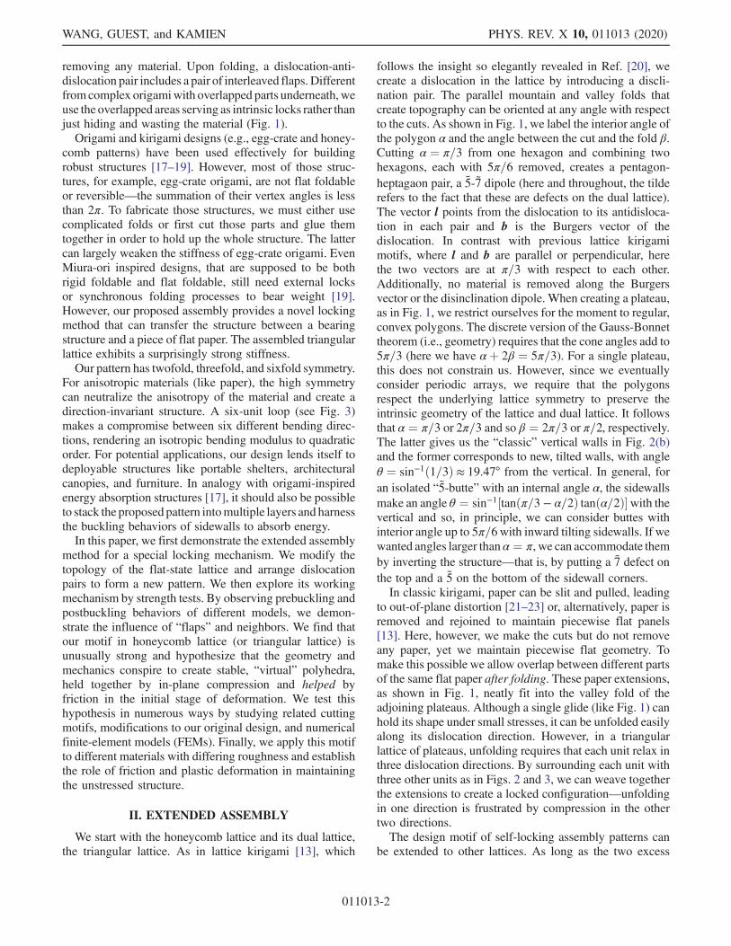
tests on the Instron 5564 with a 2 kN load cell to get force-displacement curves. Throughout, we set a loading rate of2 mm=min. We sandwiched each sample between thick,acrylic plates (the top hexagon plate mass is 61.9 g) tospread the stress evenly. The data collection was performedby Series X in Merlin software. The loading setup is shownin Fig. 4(a).The load-displacement curves are shown in Fig. 5 with
the gray region representing the error bars from fivesamples. We observe that the loading curve has threeregions: (i) the initial linear regime where the load celland six frustums are getting into full contact and each butteis independent, (ii) a new (reproducible) regime where thecollective structure is responding linearly, and (iii) the peakand beyond where the details of wall buckling give hugevariations in response—note that the final rise in forcecomes from the crushing of the crumpled paper. Thedistinction between the first and second regions is seenclearly in Fig. 5: there we see that isolated, pinned, andgapped buttes have the same response as the original modelin regime (i) and then collapse at some point. Regime (ii) isthe “post-single-butte” response and is only present in theoriginal model. Error in the linear regions (i) and (ii) arises
FIG. 2. A diagram of the interleaved kirigami extensionassembly showing the cooperative frustration between basicunits. We cut along solid lines and make mountain (M) andvalley (V) folds along dashed lines and, again, the hatched areasoverlap. (a) Template for the threefold structure with insetshowing assembled pattern (α ¼ π=3). (b) Template for thethreefold structure with inset showing assembled pattern(α ¼ 2π=3) (scale bar 1 cm).
FIG. 3. From left to right: Step-by-step assembly of the periodicplateau array. Note that this assembly requires bending of thesheets and so this structure is not rigid foldable. For clarity, thedetailed pattern on the underlying lattice is not shown. Yellowareas are the plateaus or buttes and the gray areas overlap (scalebar 1 cm).
KEEPING IT TOGETHER: INTERLEAVED KIRIGAMI … PHYS. REV. X 10, 011013 (2020)
011013-3
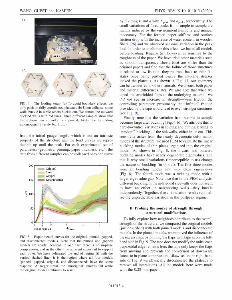
from the initial gauge length, which is not an intrinsicproperty of the structure and the load curves are repro-ducible up until the peak. For each experimental set ofparameters (geometry, pinning, paper thickness, etc.), thedata from different samples can be collapsed onto one curve
by dividing F and d with Fpeak and dpeak, respectively. Thesmall variations of force peaks from sample to sample aremainly induced by the environment humidity and manualinaccuracy. For the former, paper stiffness and surfacefriction drop with the increase of water content in woodenfibers [26] and we observed seasonal variation in the peakload. In order to ameliorate this effect, we baked all modelsbefore loading. Regime (ii), however, is sensitive to theroughness of the paper. We have tried other materials suchas smooth transparency sheets (that are stiffer than theoriginal paper) and find that the failure of those structuresis related to low friction: they returned back to their flatstates once being pushed before the in-plane stresseslocked the plateaus. As shown in Fig. 13, our geometrycan be transferred to other materials. We discuss both paperand material differences later. We also note that when wetaped the overfolded flaps to the underlying material, wedid not see an increase in strength—were friction thecontrolling parameter, presumably the “infinite” frictionprovided by the tape would lead to even stronger structures(see Fig. 9).Finally, note that the variation from sample to sample
becomes large after buckling [Fig. 4(b)]. We attribute this tohard-to-control variations in folding and cutting leading to“random” buckling of the sidewalls, either in or out. Thissensitivity arises from the nearly degenerate deformationmodes of the structure: we used FEM to calculate the linearbuckling modes of thin plates organized into the originalmodel. As shown in Fig. 8, the inward and outwardbuckling modes have nearly degenerate eigenvalues, andthis is why small variations (imperceptible to us) changethe nature of buckling (in or out). The first three modeswere all bending modes with very close eigenvalues(Fig. 8). The fourth mode was a twisting mode with alarger eigenvalue gap. Note also that in the FEM analysis,different buckling in the individual sidewalls does not seemto have an effect on neighboring walls—they buckleindependently. Together, these simulation results rational-ize the unpredictable variation in the postpeak regime.
B. Probing the source of strength throughstructural modifications
To fully explore how neighbors contribute to the overallstrength of the structure, we compared the original models(just described) with both pinned models and disconnectedmodels. In the pinned models, we removed the influence ofthe excess flaps by pinning the flaps with tape as on the left-hand side in Fig. 9. The tape does not modify the units, eachtrapezoidal edge remains free; the tape only keeps the flapsfrom moving and prevents the conversion of downwardforces to in-plane compression. Likewise, on the right-handside of Fig. 9 we physically disconnected the plateaus toremove all interactions. All the models here were madewith the 0.28 mm paper.
FIG. 4. The loading setup. (a) To avoid boundary effects, weonly push on fully coordinated plateaus. (b) Upon collapse, somewalls buckle in while others buckle out. We denote the outwardbuckled walls with red lines. Three different samples show thatthe collapse has a random component, likely due to foldinginhomogeneity (scale bar 1 cm).
FIG. 5. Experimental curves for the original, pinned, gapped,and disconnected models. Note that the pinned and gappedmodels are nearly identical: in one case there is no in-planecompression, and in the other, the adjacent edges fail to supporteach other. We have delineated the end of regime (i) with thevertical dashed line—it is the region where all four models(pinned, gapped, original, and disconnected) have the sameresponse. At larger strain, the “unoriginal” models fail whilethe original model continues to resist.
WANG, GUEST, and KAMIEN PHYS. REV. X 10, 011013 (2020)
011013-4
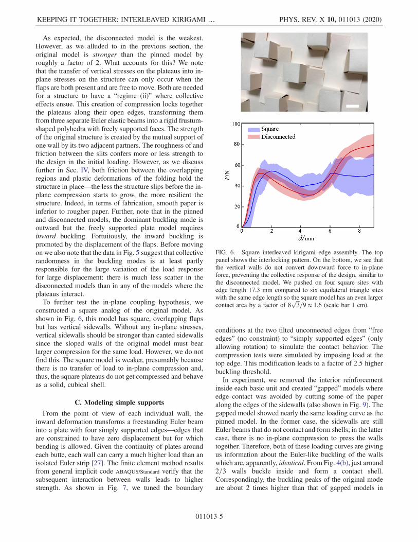
As expected, the disconnected model is the weakest.However, as we alluded to in the previous section, theoriginal model is stronger than the pinned model byroughly a factor of 2. What accounts for this? We notethat the transfer of vertical stresses on the plateaus into in-plane stresses on the structure can only occur when theflaps are both present and are free to move. Both are neededfor a structure to have a “regime (ii)” where collectiveeffects ensue. This creation of compression locks togetherthe plateaus along their open edges, transforming themfrom three separate Euler elastic beams into a rigid frustum-shaped polyhedra with freely supported faces. The strengthof the original structure is created by the mutual support ofone wall by its two adjacent partners. The roughness of andfriction between the slits confers more or less strength tothe design in the initial loading. However, as we discussfurther in Sec. IV, both friction between the overlappingregions and plastic deformations of the folding hold thestructure in place—the less the structure slips before the in-plane compression starts to grow, the more resilient thestructure. Indeed, in terms of fabrication, smooth paper isinferior to rougher paper. Further, note that in the pinnedand disconnected models, the dominant buckling mode isoutward but the freely supported plate model requiresinward buckling. Fortuitously, the inward buckling ispromoted by the displacement of the flaps. Before movingon we also note that the data in Fig. 5 suggest that collectiverandomness in the buckling modes is at least partlyresponsible for the large variation of the load responsefor large displacement: there is much less scatter in thedisconnected models than in any of the models where theplateaus interact.To further test the in-plane coupling hypothesis, we
constructed a square analog of the original model. Asshown in Fig. 6, this model has square, overlapping flapsbut has vertical sidewalls. Without any in-plane stresses,vertical sidewalls should be stronger than canted sidewallssince the sloped walls of the original model must bearlarger compression for the same load. However, we do notfind this. The square model is weaker, presumably becausethere is no transfer of load to in-plane compression and,thus, the square plateaus do not get compressed and behaveas a solid, cubical shell.
C. Modeling simple supports
From the point of view of each individual wall, theinward deformation transforms a freestanding Euler beaminto a plate with four simply supported edges—edges thatare constrained to have zero displacement but for whichbending is allowed. Given the continuity of plates aroundeach butte, each wall can carry a much higher load than anisolated Euler strip [27]. The finite element method resultsfrom general implicit code ABAQUS/Standard verify that thesubsequent interaction between walls leads to higherstrength. As shown in Fig. 7, we tuned the boundary
conditions at the two tilted unconnected edges from “freeedges” (no constraint) to “simply supported edges” (onlyallowing rotation) to simulate the contact behavior. Thecompression tests were simulated by imposing load at thetop edge. This modification leads to a factor of 2.5 higherbuckling threshold.In experiment, we removed the interior reinforcement
inside each basic unit and created “gapped” models whereedge contact was avoided by cutting some of the paperalong the edges of the sidewalls (also shown in Fig. 9). Thegapped model showed nearly the same loading curve as thepinned model. In the former case, the sidewalls are stillEuler beams that do not contact and form shells; in the lattercase, there is no in-plane compression to press the wallstogether. Therefore, both of these loading curves are givingus information about the Euler-like buckling of the wallswhich are, apparently, identical. From Fig. 4(b), just around2=3 walls buckle inside and form a contact shell.Correspondingly, the buckling peaks of the original modeare about 2 times higher than that of gapped models in
FIG. 6. Square interleaved kirigami edge assembly. The toppanel shows the interlocking pattern. On the bottom, we see thatthe vertical walls do not convert downward force to in-planeforce, preventing the collective response of the design, similar tothe disconnected model. We pushed on four square sites withedge length 17.3 mm compared to six equilateral triangle siteswith the same edge length so the square model has an even largercontact area by a factor of 8
ffiffiffi
3p
=9 ≈ 1.6 (scale bar 1 cm).
KEEPING IT TOGETHER: INTERLEAVED KIRIGAMI … PHYS. REV. X 10, 011013 (2020)
011013-5
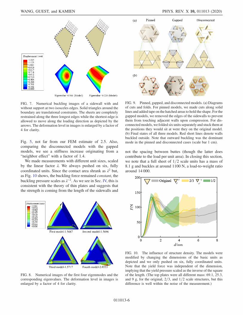
Fig. 5, not far from our FEM estimate of 2.5. Also,comparing the disconnected models with the gappedmodels, we see a stiffness increase originating from a“neighbor effect” with a factor of 1.4.We made measurements with different unit sizes, scaled
by the linear factor λ. We always pushed on six, fullycoordinated units. Since the contact area shrank as λ2 but,as Fig. 10 shows, the buckling force remained constant, thebuckling pressure scales as λ−2. As we see in Sec. IV, this isconsistent with the theory of thin plates and suggests thatthe strength is coming from the length of the sidewalls and
not the spacing between buttes (though the latter doescontribute to the load per unit area). In closing this section,we note that a full sheet of 1=2 scale units has a mass of8.1 g and buckles at around 1100 N, a load-to-weight ratioaround 14 000.
FIG. 8. Numerical images of the first four eigenmodes and thecorresponding eigenvalues. The deformation level in images isenlarged by a factor of 4 for clarity.
FIG. 9. Pinned, gapped, and disconnected models. (a) Diagramsof cuts and folds. For pinned models, we made cuts along solidlines and added tape on the hatched areas to hold the shape. For thegapped models, we removed the edges of the sidewalls to preventthem from touching adjacent walls upon compression. For dis-connectedmodels, we folded six units separately and stuck them atthe positions they would sit at were they on the original model.(b) Final states of all three models. Red short lines denote wallsbuckled outside. Note that outward buckling was the dominantmode in the pinned and disconnected cases (scale bar 1 cm).
FIG. 7. Numerical buckling images of a sidewall with andwithout support at two isosceles edges. Solid triangles around theboundary are translational constraints. The sheets are completelyrestrained along the three longest edges while the shortest edge isallowed to move along the loading direction as depicted by thearrows. The deformation level in images is enlarged by a factor of4 for clarity.
FIG. 10. The influence of structure density. The models weremodified by changing the dimensions of the basic units asdepicted and we only pushed on six, fully coordinated units.Note that the yield force was independent of the dimension,implying that the yield pressure scaled as the inverse of the squareof the length. (The top plates were all different mass: 69.1, 25.3,and 9 g, for the original, 2=3, and 1=2 scale structures, but thisdifference is well within the noise of the measurement.)
WANG, GUEST, and KAMIEN PHYS. REV. X 10, 011013 (2020)
011013-6
IV. OTHER MATERIALS AND THE ROLE OFFRICTION AND PLASTICITY
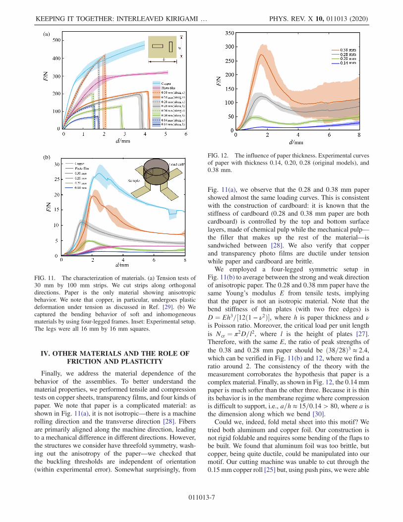
Finally, we address the material dependence of thebehavior of the assemblies. To better understand thematerial properties, we performed tensile and compressiontests on copper sheets, transparency films, and four kinds ofpaper. We note that paper is a complicated material: asshown in Fig. 11(a), it is not isotropic—there is a machinerolling direction and the transverse direction [28]. Fibersare primarily aligned along the machine direction, leadingto a mechanical difference in different directions. However,the structures we consider have threefold symmetry, wash-ing out the anisotropy of the paper—we checked thatthe buckling thresholds are independent of orientation(within experimental error). Somewhat surprisingly, from
Fig. 11(a), we observe that the 0.28 and 0.38 mm papershowed almost the same loading curves. This is consistentwith the construction of cardboard: it is known that thestiffness of cardboard (0.28 and 0.38 mm paper are bothcardboard) is controlled by the top and bottom surfacelayers, made of chemical pulp while the mechanical pulp—the filler that makes up the rest of the material—issandwiched between [28]. We also verify that copperand transparency photo films are ductile under tensionwhile paper and cardboard are brittle.We employed a four-legged symmetric setup in
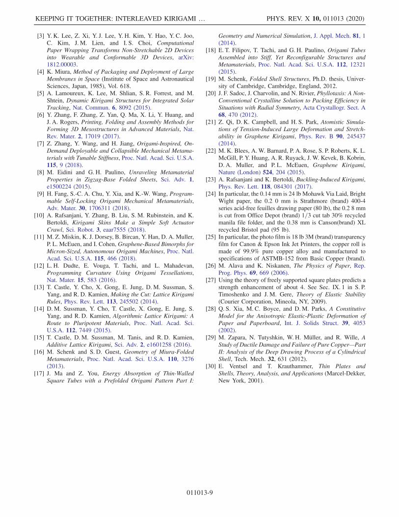
Fig. 11(b) to average between the strong and weak directionof anisotropic paper. The 0.28 and 0.38 mm paper have thesame Young’s modulus E from tensile tests, implyingthat the paper is not an isotropic material. Note that thebend stiffness of thin plates (with two free edges) isD ¼ Eh3=½12ð1 − ν2Þ�, where h is paper thickness and νis Poisson ratio. Moreover, the critical load per unit lengthis Ncr ¼ π2D=l2, where l is the height of plates [27].Therefore, with the same E, the ratio of peak strengths ofthe 0.38 and 0.28 mm paper should be ð38=28Þ3 ≈ 2.4,which can be verified in Fig. 11(b) and 12, where we find aratio around 2. The consistency of the theory with themeasurement corroborates the hypothesis that paper is acomplex material. Finally, as shown in Fig. 12, the 0.14 mmpaper is much softer than the other three. Because it is thinits behavior is in the membrane regime where compressionis difficult to support, i.e., a=h ≈ 15=0.14 > 80, where a isthe dimension along which we bend [30].Could we, indeed, fold metal sheet into this motif? We
tried both aluminum and copper foil. Our construction isnot rigid foldable and requires some bending of the flaps tobe built. We found that aluminum foil was too brittle, butcopper, being quite ductile, could be manipulated into ourmotif. Our cutting machine was unable to cut through the0.15 mm copper roll [25] but, using push pins, wewere able
FIG. 11. The characterization of materials. (a) Tension tests of30 mm by 100 mm strips. We cut strips along orthogonaldirections. Paper is the only material showing anisotropicbehavior. We note that copper, in particular, undergoes plasticdeformation under tension as discussed in Ref. [29]. (b) Wecaptured the bending behavior of soft and inhomogeneousmaterials by using four-legged frames. Inset: Experimental setup.The legs were all 16 mm by 16 mm squares.
FIG. 12. The influence of paper thickness. Experimental curvesof paper with thickness 0.14, 0.20, 0.28 (original models), and0.38 mm.
KEEPING IT TOGETHER: INTERLEAVED KIRIGAMI … PHYS. REV. X 10, 011013 (2020)
011013-7

to cut the lines manually and then fold our motif as shownin Fig. 13. Unlike paper, even smooth copper can hold itsfolded shape easily due to the ease of plastic deformation.However, to facilitate assembly, we also roughened thecopper surface with 120 grit sandpaper and we recapitulateour original observations on the cardboard—three regimes,with the second one coming from the collective strength ofthe neighbor’s effect, in-plane compression, and simplysupported Euler plates.Do our data in Fig. 13 demonstrate that both copper and
photo films, folded into the original motif, assume the same“superstrength” displayed by the paper? Using the mea-surements of the bending modulus in Fig. 11(b), we canestimate the ratio of the bend moduli of photo film to the0.28 mm paper as the ratio of the critical loads(Ncr ¼ π2D=l2), roughly 0.25, in line with the estimatefrom Fig. 13 of about 1=5. We can do the same estimatewith the copper data from Fig. 11(b) and would expect anincrease in strength of roughly 3 if the copper model haslock-in. Indeed, Fig. 13 demonstrates a comparable ratio.While the agreement is suggestive, we note that copper foilis highly plastic [29], and elasticity measurements aredelicate. In fact, our measurement of the Young’s modulusin Fig. 13(a) is off by an order of magnitude from what onewould expect from the reported value of E ∼ 120 GPa.
We also tried cutting and scoring transparency films. Weused totally scratched, partially scratched (only walls), andunscathed photo films [25] to make the motif. The threeshowed no difference in force-displacement curves. Modelsmade by original smooth films can reach the same forcepeak if, upon folding, we create plastic deformations thatallow the films to retain their shape with zero load (withoutdoing this, we found that the bending modulus of thetransparencies was enough to unfold them). Althoughstructural geometry, rather than material friction, conspiresto create colossal strength, we can save much manual effortby folding rough materials, and by keeping the structurefolded throughout deformation, friction can guarantee thatthe force peak is attained. What this demonstrates is thatthere must be someway of holding the structure together upuntil the in-plane compression generates the freely sup-ported plateau plates.
V. SUMMARY AND CONCLUSIONS
In summary, we have designed an interleaved kirigamiextension assembly and characterized its mechanical prop-erties. Not only does our pattern hold its shape throughoverlapping frictional flaps or plastic deformation of thematerial, but it conducts forces effectively betweenadjacent units through in-plane compression. We havesuggested that, in turn, the compression forces dramaticallystrengthen the structures. A variety of tests confirm thishypothesis. It would be interesting to consider other over-folded geometries to create materials that could withstandlarge shears or bending out of plane: in this case the role ofthe extensions becomes more subtle as they must respondand distort in a way that maintains the integrity of theoverlapping motif. We leave this for future work.
ACKNOWLEDGMENTS
We thank H. Ansell, J. Li, O. Parrikar, A. Seddon, andM. Tanis for discussions and the referees for their insights.We thank Y. Gao for assistance with the laser cutter andthe Instrom. This work was supported by NSF DMR12-62047 and a Simons Investigator grant from the SimonsFoundation to R. D. K., X.W. was also supported by theChina Scholarship Council. R. D. K. would like to thankthe Isaac Newton Institute for Mathematical Sciencesfor support and hospitality during the program TheMathematical Design of New Materials when work onthis paper was undertaken. This work was also supportedby EPSRC Grant No. EP/R014604/1.
[1] A. S. Gladman, E. A. Matsumoto, R. G. Nuzzo, L.Mahadevan, and J. A. Lewis, Biomimetic 4D Printing,Nat. Mater. 15, 413 (2016).
[2] L. Mahadevan and S. Rica, Self-Organized Origami, Sci-ence 307, 1740 (2005).
FIG. 13. The influence of material difference (2=3 scaleoriginal structure for copper, photo film, and paper). Top: Coppermodel (scratched) and polymer film model (unscratched). Bot-tom: Experimental curves of copper sheet, transparency films,and paper with thickness 0.28 mm (scale bar 1 cm).
WANG, GUEST, and KAMIEN PHYS. REV. X 10, 011013 (2020)
011013-8
[3] Y. K. Lee, Z. Xi, Y. J. Lee, Y. H. Kim, Y. Hao, Y. C. Joo,C. Kim, J. M. Lien, and I. S. Choi, ComputationalPaper Wrapping Transforms Non-Stretchable 2D Devicesinto Wearable and Conformable 3D Devices, arXiv:1812.00003.
[4] K. Miura, Method of Packaging and Deployment of LargeMembranes in Space (Institute of Space and AstronauticalSciences, Japan, 1985), Vol. 618.
[5] A. Lamoureux, K. Lee, M. Shlian, S. R. Forrest, and M.Shtein, Dynamic Kirigami Structures for Integrated SolarTracking, Nat. Commun. 6, 8092 (2015).
[6] Y. Zhang, F. Zhang, Z. Yan, Q. Ma, X. Li, Y. Huang, andJ. A. Rogers, Printing, Folding and Assembly Methods forForming 3D Mesostructures in Advanced Materials, Nat.Rev. Mater. 2, 17019 (2017).
[7] Z. Zhang, Y. Wang, and H. Jiang, Origami-Inspired, On-Demand Deployable and Collapsible Mechanical Metama-terials with Tunable Stiffness, Proc. Natl. Acad. Sci. U.S.A.115, 9 (2018).
[8] M. Eidini and G. H. Paulino, Unraveling MetamaterialProperties in Zigzag-Base Folded Sheets, Sci. Adv. 1,e1500224 (2015).
[9] H. Fang, S.-C. A. Chu, Y. Xia, and K.-W. Wang, Program-mable Self-Locking Origami Mechanical Metamaterials,Adv. Mater. 30, 1706311 (2018).
[10] A. Rafsanjani, Y. Zhang, B. Liu, S. M. Rubinstein, and K.Bertoldi, Kirigami Skins Make a Simple Soft ActuatorCrawl, Sci. Robot. 3, eaar7555 (2018).
[11] M. Z. Miskin, K. J. Dorsey, B. Bircan, Y. Han, D. A. Muller,P. L. McEuen, and I. Cohen, Graphene-Based Bimorphs forMicron-Sized, Autonomous Origami Machines, Proc. Natl.Acad. Sci. U.S.A. 115, 466 (2018).
[12] L. H. Dudte, E. Vouga, T. Tachi, and L. Mahadevan,Programming Curvature Using Origami Tessellations,Nat. Mater. 15, 583 (2016).
[13] T. Castle, Y. Cho, X. Gong, E. Jung, D. M. Sussman, S.Yang, and R. D. Kamien, Making the Cut: Lattice KirigamiRules, Phys. Rev. Lett. 113, 245502 (2014).
[14] D. M. Sussman, Y. Cho, T. Castle, X. Gong, E. Jung, S.Yang, and R. D. Kamien, Algorithmic Lattice Kirigami: ARoute to Pluripotent Materials, Proc. Natl. Acad. Sci.U.S.A. 112, 7449 (2015).
[15] T. Castle, D. M. Sussman, M. Tanis, and R. D. Kamien,Additive Lattice Kirigami, Sci. Adv. 2, e1601258 (2016).
[16] M. Schenk and S. D. Guest, Geometry of Miura-FoldedMetamaterials, Proc. Natl. Acad. Sci. U.S.A. 110, 3276(2013).
[17] J. Ma and Z. You, Energy Absorption of Thin-WalledSquare Tubes with a Prefolded Origami Pattern Part I:
Geometry and Numerical Simulation, J. Appl. Mech. 81, 1(2014).
[18] E. T. Filipov, T. Tachi, and G. H. Paulino, Origami TubesAssembled into Stiff, Yet Reconfigurable Structures andMetamaterials, Proc. Natl. Acad. Sci. U.S.A. 112, 12321(2015).
[19] M. Schenk, Folded Shell Structures, Ph.D. thesis, Univer-sity of Cambridge, Cambridge, England, 2012.
[20] J. F. Sadoc, J. Charvolin, and N. Rivier, Phyllotaxis: A Non-Conventional Crystalline Solution to Packing Efficiency inSituations with Radial Symmetry, Acta Crystallogr. Sect. A68, 470 (2012).
[21] Z. Qi, D. K. Campbell, and H. S. Park, Atomistic Simula-tions of Tension-Induced Large Deformation and Stretch-ability in Graphene Kirigami, Phys. Rev. B 90, 245437(2014).
[22] M. K. Blees, A.W. Barnard, P. A. Rose, S. P. Roberts, K. L.McGill, P. Y. Huang, A. R. Ruyack, J. W. Kevek, B. Kobrin,D. A. Muller, and P. L. McEuen, Graphene Kirigami,Nature (London) 524, 204 (2015).
[23] A. Rafsanjani and K. Bertoldi, Buckling-Induced Kirigami,Phys. Rev. Lett. 118, 084301 (2017).
[24] In particular, the 0.14 mm is 24 lb Mohawk Via Laid, BrightWight paper, the 0.2 0 mm is Strathmore (brand) 400-4series acid-free feuilles drawing paper (80 lb), the 0.2 8 mmis cut from Office Depot (brand) 1=3 cut tab 30% recycledmanila file folder, and the 0.38 mm is Canson(brand) XLrecycled Bristol pad (95 lb).
[25] In particular, the photo film is 18 lb 3M (brand) transparencyfilm for Canon & Epson Ink Jet Printers, the copper roll ismade of 99.9% pure copper alloy and manufactured tospecifications of ASTMB-152 from Basic Copper (brand).
[26] M. Alava and K. Niskanen, The Physics of Paper, Rep.Prog. Phys. 69, 669 (2006).
[27] Using the theory of freely supported square plates predicts astrength enhancement of about 4. See Sec. IX. 1 in S. P.Timoshenko and J. M. Gere, Theory of Elastic Stability(Courier Corporation, Mineola, NY, 2009).
[28] Q. S. Xia, M. C. Boyce, and D. M. Parks, A ConstitutiveModel for the Anisotropic Elastic-Plastic Deformation ofPaper and Paperboard, Int. J. Solids Struct. 39, 4053(2002).
[29] M. Zapara, N. Tutyshkin, W. H. Müller, and R. Wille, AStudy of Ductile Damage and Failure of Pure Copper—PartII: Analysis of the Deep Drawing Process of a CylindricalShell, Tech. Mech. 32, 631 (2012).
[30] E. Ventsel and T. Krauthammer, Thin Plates andShells, Theory, Analysis, and Applications (Marcel-Dekker,New York, 2001).
KEEPING IT TOGETHER: INTERLEAVED KIRIGAMI … PHYS. REV. X 10, 011013 (2020)
011013-9