kelley’s aviation academy - baseops · kelley’s aviation academy atp gouge fill out your form...
TRANSCRIPT
Kelley’s Aviation Academy
ATP GOUGE
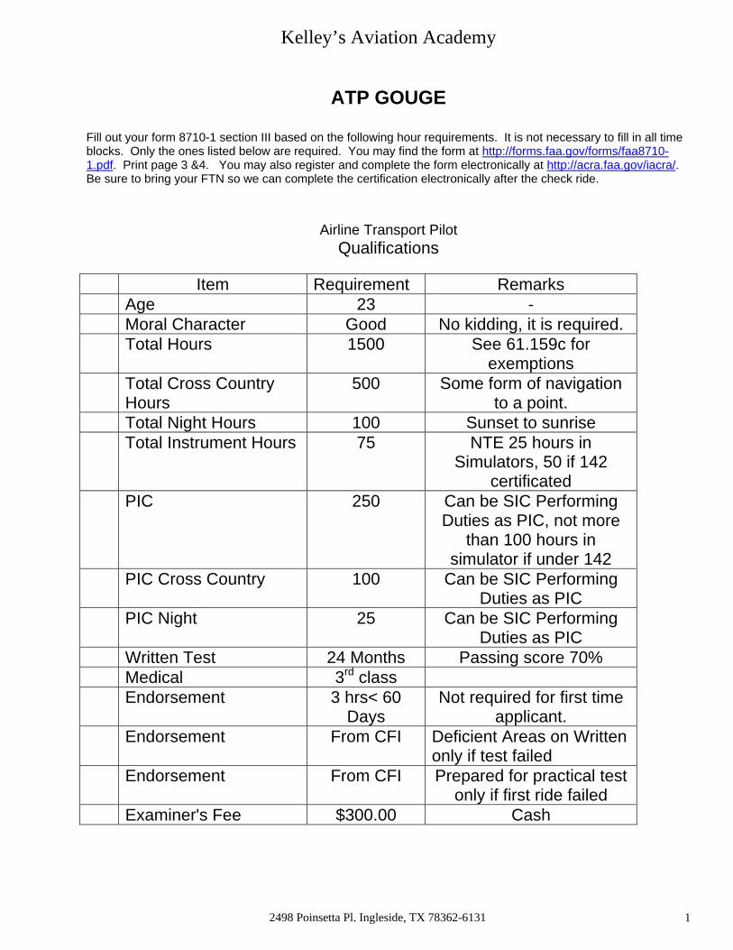
Fill out your form 8710-1 section III based on the following hour requirements. It is not necessary to fill in all time blocks. Only the ones listed below are required. You may find the form at http://forms.faa.gov/forms/faa8710-1.pdf. Print page 3 &4. You may also register and complete the form electronically at http://acra.faa.gov/iacra/. Be sure to bring your FTN so we can complete the certification electronically after the check ride.
Airline Transport Pilot
Qualifications
Item Requirement Remarks Age 23 - Moral Character Good No kidding, it is required. Total Hours 1500 See 61.159c for
exemptions Total Cross Country
Hours 500 Some form of navigation
to a point. Total Night Hours 100 Sunset to sunrise Total Instrument Hours 75 NTE 25 hours in
Simulators, 50 if 142 certificated
PIC 250 Can be SIC Performing Duties as PIC, not more
than 100 hours in simulator if under 142
PIC Cross Country 100 Can be SIC Performing Duties as PIC
PIC Night 25 Can be SIC Performing Duties as PIC
Written Test 24 Months Passing score 70% Medical 3rd class Endorsement 3 hrs< 60
Days Not required for first time
applicant. Endorsement From CFI Deficient Areas on Written
only if test failed Endorsement From CFI Prepared for practical test
only if first ride failed Examiner's Fee $300.00 Cash
2498 Poinsetta Pl. Ingleside, TX 78362-6131 1

Kelley’s Aviation Academy
I. Area of Operation: Preflight Preparation
Task: Equipment Examination
Exhibit adequate knowledge appropriate to the airplane, systems and components; normal, abnormal and EPs re: the following items
VII. Area of Operation: Normal and Abnormal Procedures
Adequate knowledge of normal and abnormal procedures of the systems, subsystems, etc.
Demonstrates proper use of systems, etc. such as:
Powerplant - Controls and indicators, induction system, carburetor and fuel injection, turbocharging, cooling, fire detection/protection, mounting points, deicing/anti-icing and related components
Oil system - Capacity, grade, quantities, indicators
Fuel system - Capacity, drains, pumps, controls, crossfeed, fuel grade/color
Landing gear – Indicators, brakes, anti-skid, tires, nosewheel steering, and shock absorbers
Propellers - Type controls, feathering/unfeathering, autofeather, synchronizing
Hydraulic system – Capacity, pumps, pressure, reservoir, grade
Electrical system - Alternators, generators, battery, CBs, APUs
Environmental systems - Heating, cooling, ventilation, oxygen and pressurization
Ice protection – Airframe antiice, deice, pitot static system protection, propeller, windshield, wing and tail surfaces
Crewmember and passenger equipment – Oxygen, survival gear, emergency exits
Flight controls – Ailerons, elevators, rudders, stabilizers, flaps, spoilers, trim systems
Pitot-static system – Associated instruments and power sources
Fire detection and extinguishing systems
Avionics and communication, Navigation systems
2498 Poinsetta Pl. Ingleside, TX 78362-6131 2
Kelley’s Aviation Academy
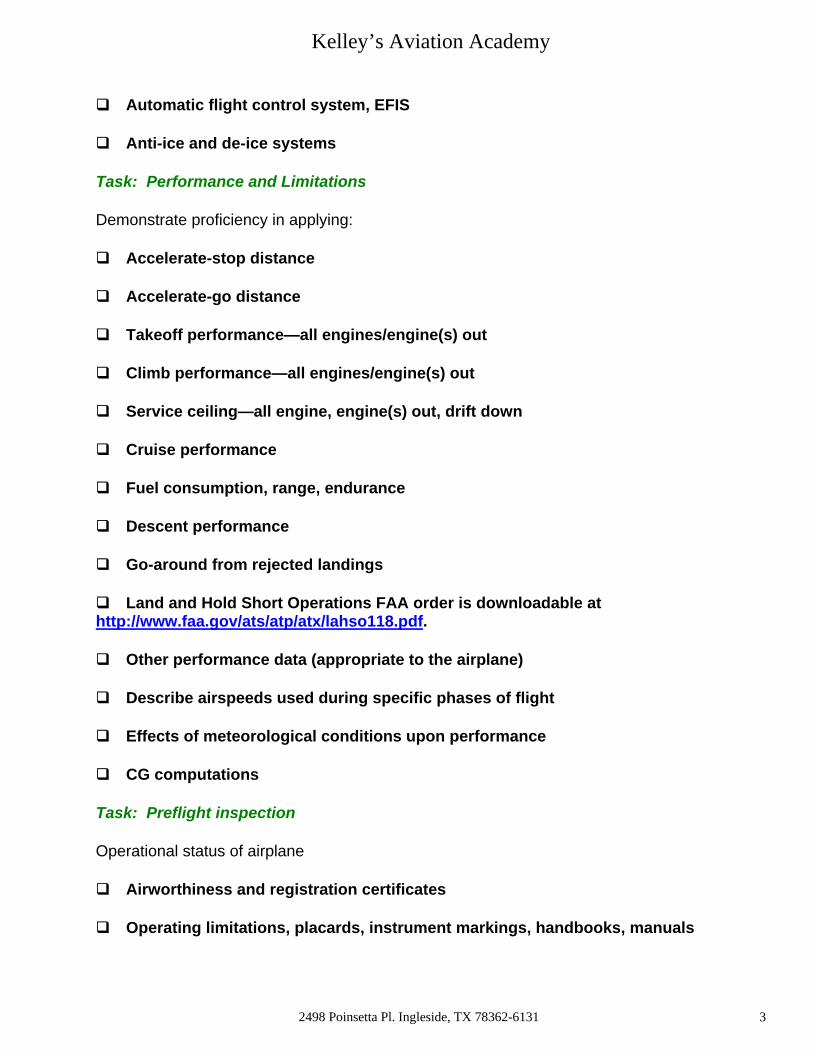
Automatic flight control system, EFIS
Anti-ice and de-ice systems
Task: Performance and Limitations
Demonstrate proficiency in applying:
Accelerate-stop distance
Accelerate-go distance
Takeoff performance—all engines/engine(s) out
Climb performance—all engines/engine(s) out
Service ceiling—all engine, engine(s) out, drift down
Cruise performance
Fuel consumption, range, endurance
Descent performance
Go-around from rejected landings
Land and Hold Short Operations FAA order is downloadable at http://www.faa.gov/ats/atp/atx/lahso118.pdf.
Other performance data (appropriate to the airplane)
Describe airspeeds used during specific phases of flight
Effects of meteorological conditions upon performance
CG computations
Task: Preflight inspection
Operational status of airplane
Airworthiness and registration certificates
Operating limitations, placards, instrument markings, handbooks, manuals
2498 Poinsetta Pl. Ingleside, TX 78362-6131 3
Kelley’s Aviation Academy
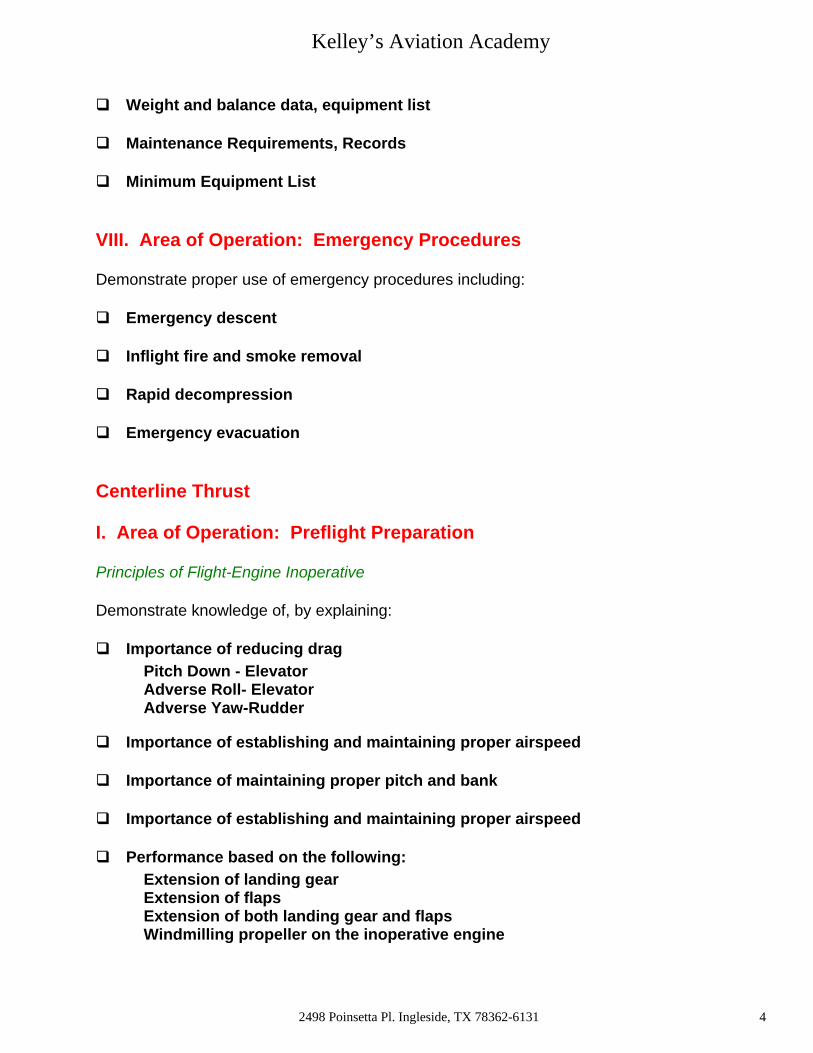
Weight and balance data, equipment list
Maintenance Requirements, Records
Minimum Equipment List
VIII. Area of Operation: Emergency Procedures
Demonstrate proper use of emergency procedures including:
Emergency descent
Inflight fire and smoke removal
Rapid decompression
Emergency evacuation
Centerline Thrust
I. Area of Operation: Preflight Preparation
Principles of Flight-Engine Inoperative
Demonstrate knowledge of, by explaining:
Importance of reducing drag Pitch Down - Elevator
Adverse Roll- Elevator Adverse Yaw-Rudder
Importance of establishing and maintaining proper airspeed
Importance of maintaining proper pitch and bank
Importance of establishing and maintaining proper airspeed
Performance based on the following: Extension of landing gear Extension of flaps Extension of both landing gear and flaps Windmilling propeller on the inoperative engine
2498 Poinsetta Pl. Ingleside, TX 78362-6131 4

Kelley’s Aviation Academy
2498 Poinsetta Pl. Ingleside, TX 78362-6131 5

Kelley’s Aviation Academy
VII. Area of Operation: Engine Inoperative-Loss of Directional Control
Demonstrate knowledge of, by explaining:
Meaning of ‘critical engine” Torque Spiraling Slipstream P Factor Accelerated Slipstream
Effects of: Density Altitude Weight Center of Gravity Relationship of stall speed to VMC
Reasons for loss of directional control
2498 Poinsetta Pl. Ingleside, TX 78362-6131 6

Kelley’s Aviation Academy
PREFLIGHT PREPARATION AND FLIGHT PLANNING Whether the flight is to be local or cross-country, certain preflight items need to be reviewed and accomplished. 14 CFR part 91 requires that before each flight, the pilot shall become familiar with all available information concerning the flight. For all flights, this includes runway lengths, and takeoff and landing distances. For flights not in the vicinity of an airport, the pilot must be familiar with: • weather reports and forecasts; • fuel requirements; • alternate/diversion plans; and • known traffic delays. The best sources of information for airplane performance data are the AFM/POH. The best sources for preflight weather and Notices to Airmen (NOTAM’s) information are FAA Automated Flight Service Stations (AFSS) or direct user access terminal systems (DUATS). Airport, navigation, and communication information can be derived from the Airport/Facility Directory. Based on a review of this information, particularly the weather conditions, fuel requirements, and pilot qualifications, a decision can be made on whether to begin the flight, or to cancel and reschedule. AIRPLANE PREFLIGHT INSPECTION The accomplishment of a safe flight includes a careful preflight inspection of the airplane. The preflight inspection is conducted with a checklist and helps determine if the airplane is in an airworthy condition for the intended flight. Certificates and Documents Airworthiness of the airplane is determined, in part, by the following certificates and documents, which must be on board the airplane when operated. • Airworthiness certificate. • Registration certificate. • Radio Station License issued by the Federal Communications Commission (FCC), if the radio transmitter is to be operated outside of the United States. • Operating limitations. These may take the form of an FAA-approved AFM/POH, placards, and instrument markings, or any combination of the above. A complete preflight inspection includes a review of the airplane logbooks. These are not required to be kept in the airplane when it is operated, and most owners keep them in a secure location. There will be maintenance records for the airframe and engine. Most owners also maintain additional propeller records. At a minimum, there should be an annual inspection within the preceding 12-calendar months. When the airplane is operated carrying persons for hire or giving flight instruction for hire, a 100-hour inspection is required by 14 CFR part 91. An annual inspection may be performed in lieu of a 100-hour inspection. If the transponder is to be used, it is required to be inspected within the preceding 24-calendar months. If the airplane is operated under instrument flight rules (IFR) in controlled airspace, the pitot-static system also is required to be inspected within the preceding 24-calendar months. The emergency locator transmitter (ELT) should also be checked. The ELT is battery powered, and the battery replacement or recharge date should not be exceeded. Airworthiness Directives (AD’s) have a variety of compliance intervals and are usually tracked in a separate area of the appropriate airframe, engine, or propeller record. Maintenance status boards or other maintenance tracking systems used in many operations are useful inspection interval reminders, but official airworthiness and inspection status can only be determined from the records themselves.
2498 Poinsetta Pl. Ingleside, TX 78362-6131 7

Kelley’s Aviation Academy
MINIMUM EQUIPMENT LISTS (MEL’s) AND OPERATIONS WITH INOPERATIVE EQUIPMENT The Code of Federal Regulations (CFR’s) requires that all aircraft instruments and installed equipment is operative prior to each departure. When the FAA adopted the minimum equipment list (MEL) concept for 14 CFR part 91 operations, this allowed for the first time, operations with inoperative items determined to be nonessential for safe flight. At the same time, it allowed part 91 operators, without an MEL, to defer repairs on nonessential equipment within the guidelines of part 91. There are two primary methods of deferring maintenance on small, non-turbine powered airplanes operated under part 91. They are the deferral provision of 14 CFR part 91, section 91.213(d) and an FAA-approved MEL. The deferral provision of section 91.213(d) is widely used by most pilot/operators. Its popularity is due to simplicity and minimal paperwork. When inoperative equipment is found during preflight or prior to departure, the decision should be to cancel the flight, obtain maintenance prior to flight, or to defer the item or equipment. Maintenance deferrals are not used for inflight discrepancies. The manufacturer’s AFM/POH procedures are to be used in those situations. The discussion that follows assumes that the pilot wishes to defer maintenance that would ordinarily be required prior to flight. Using the deferral provision of section 91.213(d), the pilot determines whether the inoperative equipment is required by type design, the CFR’s, or AD’s. If the inoperative item is not required, and the airplane can be safely operated without it, the deferral may be made. The inoperative item shall be deactivated or removed and an INOPERATIVE placard placed near the appropriate switch, control, or indicator. If deactivation or removal involves maintenance (removal always will), it must be accomplished by certificated maintenance personnel. For example, if the position lights (installed equipment) were discovered to be inoperative prior to a daytime flight, the pilot would follow the requirements of section 91.213(d). The deactivation may be a process as simple as the pilot positioning a circuit breaker to the OFF position, or as complex as rendering instruments or equipment totally inoperable. Complex maintenance tasks require a certificated and appropriately rated maintenance person to perform the deactivation. In all cases, the item or equipment must be placarded INOPERATIVE. All small, non-turbine powered airplanes operated under part 91 are eligible to use the maintenance deferral provisions of section 91.213(d). However, once an operator requests an MEL, and a Letter of Authorization (LOA) is issued by the FAA, then the use of the MEL becomes mandatory for that airplane. All maintenance deferrals must be accomplished in accordance with the terms and conditions of the MEL and the operator-generated procedures document. The use of an MEL for a small, non-turbine powered airplane operated under part 91 also allows for the deferral of inoperative items or equipment. The primary guidance becomes the FAA-approved MEL issued to that specific operator and N-numbered airplane. The FAA has developed master minimum equipment lists (MMEL’s) for airplanes in current use. Upon written request by an airplane operator, the local FAA Flight Standards District Office (FSDO) may issue the appropriate make and model MMEL, along with an LOA, and the preamble. The operator then develops operations and maintenance (O&M) procedures from the MMEL. This MMEL with O&M procedures now becomes the operator’s MEL. The MEL, LOA, preamble, and procedures document developed by the operator must be on board the airplane when it is operated. The FAA considers an approved MEL to be a supplemental type certificate (STC) issued to an aircraft by serial number and registration number. It therefore becomes the authority to operate that aircraft in a condition other than originally type certificated.
2498 Poinsetta Pl. Ingleside, TX 78362-6131 8

Kelley’s Aviation Academy
With an approved MEL, if the position lights were discovered inoperative prior to a daytime flight, the pilot would make an entry in the maintenance record or discrepancy record provided for that purpose. The item is then either repaired or deferred in accordance with the MEL. Upon confirming that daytime flight with inoperative position lights is acceptable in accordance with the provisions of the MEL, the pilot would leave the position lights switch OFF, open the circuit breaker (or whatever action is called for in the procedures document), and placard the position light switch as INOPERATIVE. There are exceptions to the use of the MEL for deferral. For example, should a component fail that is not listed in the MEL as deferrable (the tachometer, wing’s flaps, or stall warning device, for example), then repairs are required to be performed prior to departure. If maintenance or parts are not readily available at that location, a special flight permit can be obtained from the nearest FSDO. This permit allows the airplane to be flown to another location for maintenance. This allows an aircraft that may not currently meet applicable airworthiness requirements, but is capable of safe flight, to be operated under the restrictive special terms and conditions attached to the special flight permit. Deferral of maintenance is not to be taken lightly, and due consideration should be given to the effect an inoperative component may have on the operation of an airplane, particularly if other items are inoperative. Further information regarding MEL’s and operations with inoperative equipment can be found in AC 91-67, Minimum Equipment Requirements for General Aviation Operations Under FAR Part 91.
91.205 Powered civil aircraft with standard category U.S. airworthiness certificates: Instrument and equipment requirements.
(a) General. Except as provided in paragraphs (c)(3) and (e) of this section, no person may operate a powered civil aircraft with a standard category U.S. airworthiness certificate in any operation described in paragraphs (b) through (f) of this section unless that aircraft contains the instruments and equipment specified in those paragraphs (or FAA-approved equivalents) for that type of operation, and those instruments and items of equipment are in operable condition.
(b) Visual-flight rules (day). For VFR flight during the day, the following instruments and equipment are required:
(1) Airspeed indicator.
(2) Altimeter.
(3) Magnetic direction indicator.
(4) Tachometer for each engine.
(5) Oil pressure gauge for each engine using pressure system.
(6) Temperature gauge for each liquid-cooled engine.
(7) Oil temperature gauge for each air-cooled engine.
(8) Manifold pressure gauge for each altitude engine.
(9) Fuel gauge indicating the quantity of fuel in each tank.
2498 Poinsetta Pl. Ingleside, TX 78362-6131 9
Kelley’s Aviation Academy
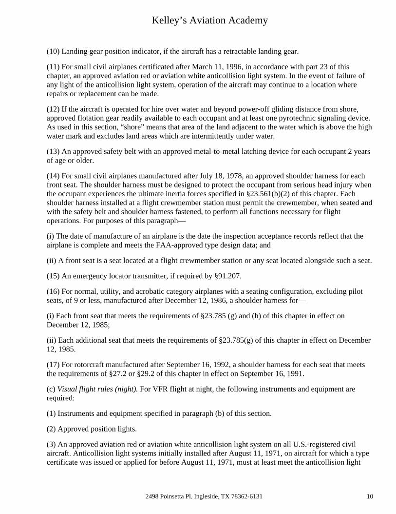
(10) Landing gear position indicator, if the aircraft has a retractable landing gear.
(11) For small civil airplanes certificated after March 11, 1996, in accordance with part 23 of this chapter, an approved aviation red or aviation white anticollision light system. In the event of failure of any light of the anticollision light system, operation of the aircraft may continue to a location where repairs or replacement can be made.
(12) If the aircraft is operated for hire over water and beyond power-off gliding distance from shore, approved flotation gear readily available to each occupant and at least one pyrotechnic signaling device. As used in this section, “shore” means that area of the land adjacent to the water which is above the high water mark and excludes land areas which are intermittently under water.
(13) An approved safety belt with an approved metal-to-metal latching device for each occupant 2 years of age or older.
(14) For small civil airplanes manufactured after July 18, 1978, an approved shoulder harness for each front seat. The shoulder harness must be designed to protect the occupant from serious head injury when the occupant experiences the ultimate inertia forces specified in §23.561(b)(2) of this chapter. Each shoulder harness installed at a flight crewmember station must permit the crewmember, when seated and with the safety belt and shoulder harness fastened, to perform all functions necessary for flight operations. For purposes of this paragraph—
(i) The date of manufacture of an airplane is the date the inspection acceptance records reflect that the airplane is complete and meets the FAA-approved type design data; and
(ii) A front seat is a seat located at a flight crewmember station or any seat located alongside such a seat.
(15) An emergency locator transmitter, if required by §91.207.
(16) For normal, utility, and acrobatic category airplanes with a seating configuration, excluding pilot seats, of 9 or less, manufactured after December 12, 1986, a shoulder harness for—
(i) Each front seat that meets the requirements of §23.785 (g) and (h) of this chapter in effect on December 12, 1985;
(ii) Each additional seat that meets the requirements of §23.785(g) of this chapter in effect on December 12, 1985.
(17) For rotorcraft manufactured after September 16, 1992, a shoulder harness for each seat that meets the requirements of §27.2 or §29.2 of this chapter in effect on September 16, 1991.
(c) Visual flight rules (night). For VFR flight at night, the following instruments and equipment are required:
(1) Instruments and equipment specified in paragraph (b) of this section.
(2) Approved position lights.
(3) An approved aviation red or aviation white anticollision light system on all U.S.-registered civil aircraft. Anticollision light systems initially installed after August 11, 1971, on aircraft for which a type certificate was issued or applied for before August 11, 1971, must at least meet the anticollision light
2498 Poinsetta Pl. Ingleside, TX 78362-6131 10
Kelley’s Aviation Academy
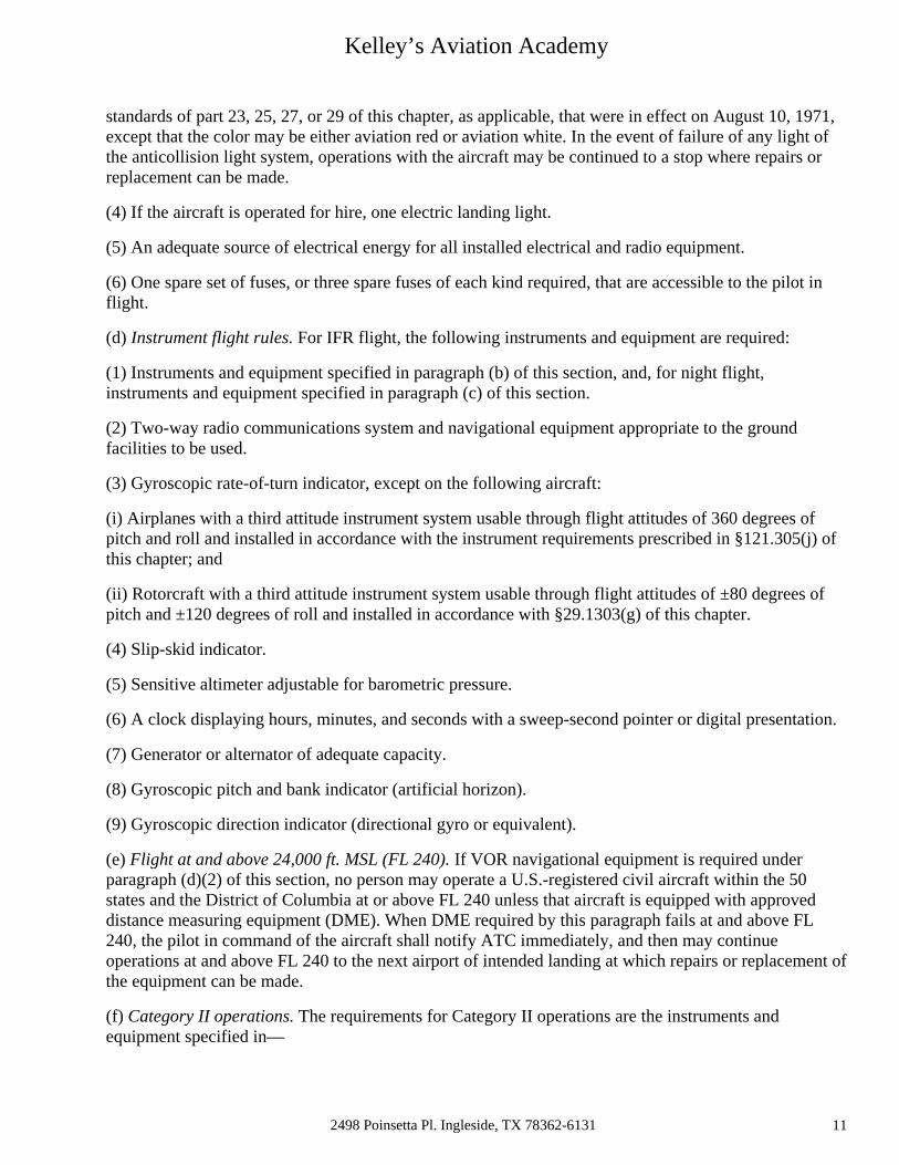
standards of part 23, 25, 27, or 29 of this chapter, as applicable, that were in effect on August 10, 1971, except that the color may be either aviation red or aviation white. In the event of failure of any light of the anticollision light system, operations with the aircraft may be continued to a stop where repairs or replacement can be made.
(4) If the aircraft is operated for hire, one electric landing light.
(5) An adequate source of electrical energy for all installed electrical and radio equipment.
(6) One spare set of fuses, or three spare fuses of each kind required, that are accessible to the pilot in flight.
(d) Instrument flight rules. For IFR flight, the following instruments and equipment are required:
(1) Instruments and equipment specified in paragraph (b) of this section, and, for night flight, instruments and equipment specified in paragraph (c) of this section.
(2) Two-way radio communications system and navigational equipment appropriate to the ground facilities to be used.
(3) Gyroscopic rate-of-turn indicator, except on the following aircraft:
(i) Airplanes with a third attitude instrument system usable through flight attitudes of 360 degrees of pitch and roll and installed in accordance with the instrument requirements prescribed in §121.305(j) of this chapter; and
(ii) Rotorcraft with a third attitude instrument system usable through flight attitudes of ±80 degrees of pitch and ±120 degrees of roll and installed in accordance with §29.1303(g) of this chapter.
(4) Slip-skid indicator.
(5) Sensitive altimeter adjustable for barometric pressure.
(6) A clock displaying hours, minutes, and seconds with a sweep-second pointer or digital presentation.
(7) Generator or alternator of adequate capacity.
(8) Gyroscopic pitch and bank indicator (artificial horizon).
(9) Gyroscopic direction indicator (directional gyro or equivalent).
(e) Flight at and above 24,000 ft. MSL (FL 240). If VOR navigational equipment is required under paragraph (d)(2) of this section, no person may operate a U.S.-registered civil aircraft within the 50 states and the District of Columbia at or above FL 240 unless that aircraft is equipped with approved distance measuring equipment (DME). When DME required by this paragraph fails at and above FL 240, the pilot in command of the aircraft shall notify ATC immediately, and then may continue operations at and above FL 240 to the next airport of intended landing at which repairs or replacement of the equipment can be made.
(f) Category II operations. The requirements for Category II operations are the instruments and equipment specified in—
2498 Poinsetta Pl. Ingleside, TX 78362-6131 11

Kelley’s Aviation Academy
(1) Paragraph (d) of this section; and
(2) Appendix A to this part.
(g) Category III operations. The instruments and equipment required for Category III operations are specified in paragraph (d) of this section.
(h) Exclusions. Paragraphs (f) and (g) of this section do not apply to operations conducted by a holder of a certificate issued under part 121 or part 135 of this chapter.
91.207 Emergency locator transmitters.
(a) Except as provided in paragraphs (e) and (f) of this section, no person may operate a U.S.-registered civil airplane unless—
(1) There is attached to the airplane an approved automatic type emergency locator transmitter that is in operable condition for the following operations, except that after June 21, 1995, an emergency locator transmitter that meets the requirements of TSO-C91 may not be used for new installations:
(i) Those operations governed by the supplemental air carrier and commercial operator rules of parts 121 and 125;
(ii) Charter flights governed by the domestic and flag air carrier rules of part 121 of this chapter; and
(iii) Operations governed by part 135 of this chapter; or
(2) For operations other than those specified in paragraph (a)(1) of this section, there must be attached to the airplane an approved personal type or an approved automatic type emergency locator transmitter that is in operable condition, except that after June 21, 1995, an emergency locator transmitter that meets the requirements of TSO-C91 may not be used for new installations.
(b) Each emergency locator transmitter required by paragraph (a) of this section must be attached to the airplane in such a manner that the probability of damage to the transmitter in the event of crash impact is minimized. Fixed and deployable automatic type transmitters must be attached to the airplane as far aft as practicable.
(c) Batteries used in the emergency locator transmitters required by paragraphs (a) and (b) of this section must be replaced (or recharged, if the batteries are rechargeable)—
(1) When the transmitter has been in use for more than 1 cumulative hour; or
(2) When 50 percent of their useful life (or, for rechargeable batteries, 50 percent of their useful life of charge) has expired, as established by the transmitter manufacturer under its approval.
The new expiration date for replacing (or recharging) the battery must be legibly marked on the outside of the transmitter and entered in the aircraft maintenance record. Paragraph (c)(2) of this section does not apply to batteries (such as water-activated batteries) that are essentially unaffected during probable storage intervals.
2498 Poinsetta Pl. Ingleside, TX 78362-6131 12
Kelley’s Aviation Academy
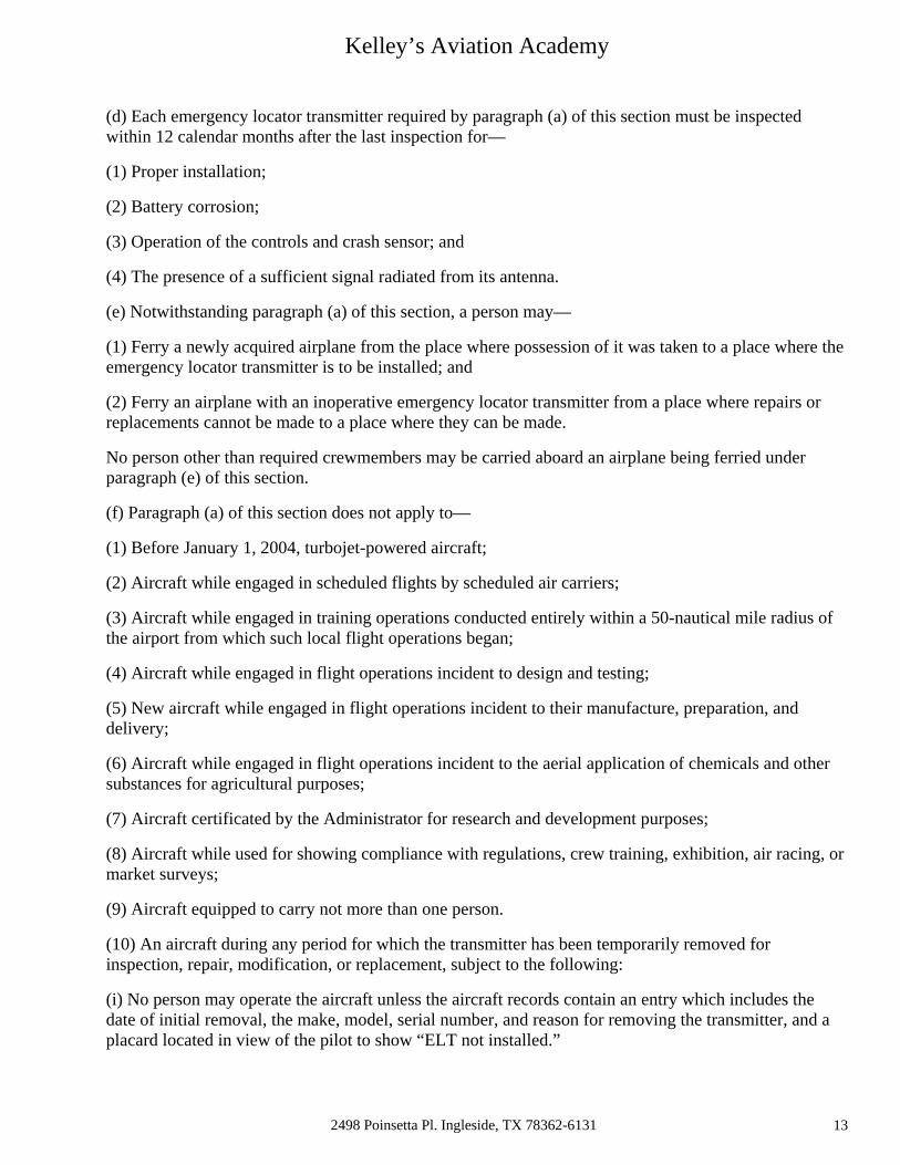
(d) Each emergency locator transmitter required by paragraph (a) of this section must be inspected within 12 calendar months after the last inspection for—
(1) Proper installation;
(2) Battery corrosion;
(3) Operation of the controls and crash sensor; and
(4) The presence of a sufficient signal radiated from its antenna.
(e) Notwithstanding paragraph (a) of this section, a person may—
(1) Ferry a newly acquired airplane from the place where possession of it was taken to a place where the emergency locator transmitter is to be installed; and
(2) Ferry an airplane with an inoperative emergency locator transmitter from a place where repairs or replacements cannot be made to a place where they can be made.
No person other than required crewmembers may be carried aboard an airplane being ferried under paragraph (e) of this section.
(f) Paragraph (a) of this section does not apply to—
(1) Before January 1, 2004, turbojet-powered aircraft;
(2) Aircraft while engaged in scheduled flights by scheduled air carriers;
(3) Aircraft while engaged in training operations conducted entirely within a 50-nautical mile radius of the airport from which such local flight operations began;
(4) Aircraft while engaged in flight operations incident to design and testing;
(5) New aircraft while engaged in flight operations incident to their manufacture, preparation, and delivery;
(6) Aircraft while engaged in flight operations incident to the aerial application of chemicals and other substances for agricultural purposes;
(7) Aircraft certificated by the Administrator for research and development purposes;
(8) Aircraft while used for showing compliance with regulations, crew training, exhibition, air racing, or market surveys;
(9) Aircraft equipped to carry not more than one person.
(10) An aircraft during any period for which the transmitter has been temporarily removed for inspection, repair, modification, or replacement, subject to the following:
(i) No person may operate the aircraft unless the aircraft records contain an entry which includes the date of initial removal, the make, model, serial number, and reason for removing the transmitter, and a placard located in view of the pilot to show “ELT not installed.”
2498 Poinsetta Pl. Ingleside, TX 78362-6131 13

Kelley’s Aviation Academy
(ii) No person may operate the aircraft more than 90 days after the ELT is initially removed from the aircraft; and
(11) On and after January 1, 2004, aircraft with a maximum payload capacity of more than 18,000 pounds when used in air transportation.
91.213 Inoperative instruments and equipment. Link to an amendment published at 69 FR 44880, July 27, 2004.(a) Except as provided in paragraph (d) of this section, no person may take off an aircraft with inoperative instruments or equipment installed unless the following conditions are met:
(1) An approved Minimum Equipment List exists for that aircraft.
(2) The aircraft has within it a letter of authorization, issued by the FAA Flight Standards district office having jurisdiction over the area in which the operator is located, authorizing operation of the aircraft under the Minimum Equipment List. The letter of authorization may be obtained by written request of the airworthiness certificate holder. The Minimum Equipment List and the letter of authorization constitute a supplemental type certificate for the aircraft.
(3) The approved Minimum Equipment List must—
(i) Be prepared in accordance with the limitations specified in paragraph (b) of this section; and
(ii) Provide for the operation of the aircraft with the instruments and equipment in an inoperable condition.
(4) The aircraft records available to the pilot must include an entry describing the inoperable instruments and equipment.
(5) The aircraft is operated under all applicable conditions and limitations contained in the Minimum Equipment List and the letter authorizing the use of the list.
(b) The following instruments and equipment may not be included in a Minimum Equipment List:
(1) Instruments and equipment that are either specifically or otherwise required by the airworthiness requirements under which the aircraft is type certificated and which are essential for safe operations under all operating conditions.
(2) Instruments and equipment required by an airworthiness directive to be in operable condition unless the airworthiness directive provides otherwise.
(3) Instruments and equipment required for specific operations by this part.
(c) A person authorized to use an approved Minimum Equipment List issued for a specific aircraft under subpart K of this part, part 121, 125, or 135 of this chapter must use that Minimum Equipment List to comply with the requirements in this section.
2498 Poinsetta Pl. Ingleside, TX 78362-6131 14
Kelley’s Aviation Academy
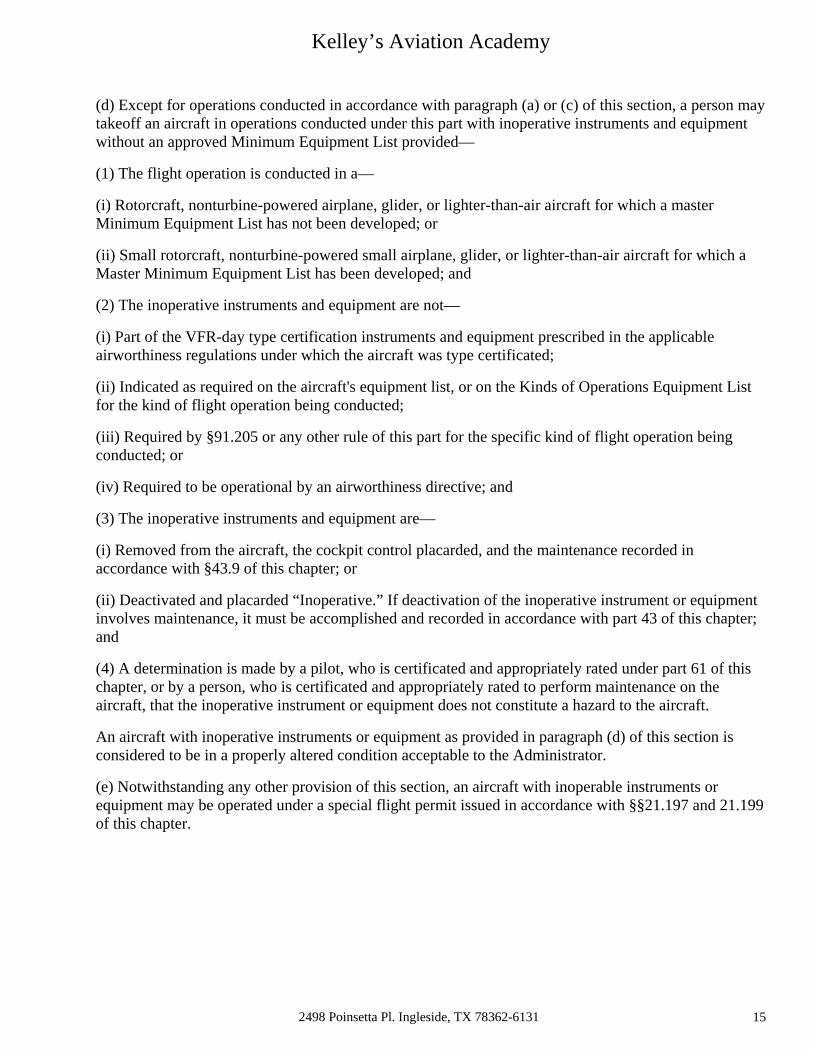
(d) Except for operations conducted in accordance with paragraph (a) or (c) of this section, a person may takeoff an aircraft in operations conducted under this part with inoperative instruments and equipment without an approved Minimum Equipment List provided—
(1) The flight operation is conducted in a—
(i) Rotorcraft, nonturbine-powered airplane, glider, or lighter-than-air aircraft for which a master Minimum Equipment List has not been developed; or
(ii) Small rotorcraft, nonturbine-powered small airplane, glider, or lighter-than-air aircraft for which a Master Minimum Equipment List has been developed; and
(2) The inoperative instruments and equipment are not—
(i) Part of the VFR-day type certification instruments and equipment prescribed in the applicable airworthiness regulations under which the aircraft was type certificated;
(ii) Indicated as required on the aircraft's equipment list, or on the Kinds of Operations Equipment List for the kind of flight operation being conducted;
(iii) Required by §91.205 or any other rule of this part for the specific kind of flight operation being conducted; or
(iv) Required to be operational by an airworthiness directive; and
(3) The inoperative instruments and equipment are—
(i) Removed from the aircraft, the cockpit control placarded, and the maintenance recorded in accordance with §43.9 of this chapter; or
(ii) Deactivated and placarded “Inoperative.” If deactivation of the inoperative instrument or equipment involves maintenance, it must be accomplished and recorded in accordance with part 43 of this chapter; and
(4) A determination is made by a pilot, who is certificated and appropriately rated under part 61 of this chapter, or by a person, who is certificated and appropriately rated to perform maintenance on the aircraft, that the inoperative instrument or equipment does not constitute a hazard to the aircraft.
An aircraft with inoperative instruments or equipment as provided in paragraph (d) of this section is considered to be in a properly altered condition acceptable to the Administrator.
(e) Notwithstanding any other provision of this section, an aircraft with inoperable instruments or equipment may be operated under a special flight permit issued in accordance with §§21.197 and 21.199 of this chapter.
2498 Poinsetta Pl. Ingleside, TX 78362-6131 15
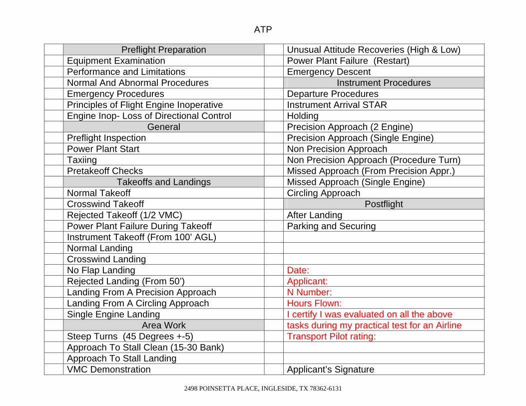
ATP Preflight Preparation Unusual Attitude Recoveries (High & Low) Equipment Examination Power Plant Failure (Restart) Performance and Limitations Emergency Descent Normal And Abnormal Procedures Instrument Procedures Emergency Procedures Departure Procedures Principles of Flight Engine Inoperative Instrument Arrival STAR Engine Inop- Loss of Directional Control Holding General Precision Approach (2 Engine) Preflight Inspection Precision Approach (Single Engine) Power Plant Start Non Precision Approach Taxiing Non Precision Approach (Procedure Turn) Pretakeoff Checks Missed Approach (From Precision Appr.) Takeoffs and Landings Missed Approach (Single Engine) Normal Takeoff Circling Approach Crosswind Takeoff Postflight Rejected Takeoff (1/2 VMC) After Landing Power Plant Failure During Takeoff Parking and Securing Instrument Takeoff (From 100’ AGL) Normal Landing Crosswind Landing No Flap Landing Date: Rejected Landing (From 50’) Applicant: Landing From A Precision Approach N Number: Landing From A Circling Approach Hours Flown: Single Engine Landing I certify I was evaluated on all the above Area Work tasks during my practical test for an Airline Steep Turns (45 Degrees +-5) Transport Pilot rating: Approach To Stall Clean (15-30 Bank) Approach To Stall Landing VMC Demonstration Applicant’s Signature
2498 POINSETTA PLACE, INGLESIDE, TX 78362-6131
Kelley’s Aviation Academy
2498 P0insettta Pl. Ingleside TX 78362-6131 17
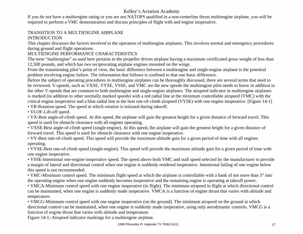
If you do not have a multiengine rating or you are not NATOPS qualified in a non-centerline thrust multiengine airplane, you will be required to perform a VMC demonstration and discuss principles of flight with and engine inoperative. TRANSITION TO A MULTIENGINE AIRPLANE INTRODUCTION This chapter discusses the factors involved in the operation of multiengine airplanes. This involves normal and emergency procedures during ground and flight operations. MULTIENGINE PERFORMANCE CHARACTERISTICS The term “multiengine” as used here pertains to the propeller driven airplane having a maximum certificated gross weight of less than 12,500 pounds, and which has two reciprocating airplane engines mounted on the wings. From the transitioning pilot’s point of view, the basic difference between a multiengine and single-engine airplane is the potential problem involving engine failure. The information that follows is confined to that one basic difference. Before the subject of operating procedures in multiengine airplanes can be thoroughly discussed, there are several terms that need to be reviewed. V-speeds, such as VXSE, VYSE, VSSE, and VMC are the new speeds the multiengine pilot needs to know in addition to the other V-speeds that are common to both multiengine and single-engine airplanes. The airspeed indicator in multiengine airplanes is marked (in addition to other normally marked speeds) with a red radial line at the minimum controllable airspeed (VMC) with the critical engine inoperative and a blue radial line at the best rate-of-climb airspeed (VYSE) with one engine inoperative. [Figure 14-1] • VR-Rotation speed. The speed at which rotation is initiated during takeoff. • VLOF-Lift-off speed. • VX-Best angle-of-climb speed. At this speed, the airplane will gain the greatest height for a given distance of forward travel. This speed is used for obstacle clearance with all engines operating. • VXSE-Best angle-of-climb speed (single-engine). At this speed, the airplane will gain the greatest height for a given distance of forward travel. This speed is used for obstacle clearance with one engine inoperative. • VY-Best rate-of-climb speed. This speed will provide the maximum altitude gain for a given period of time with all engines operating. • VYSE-Best rate-of-climb speed (single-engine). This speed will provide the maximum altitude gain for a given period of time with one engine inoperative. • VSSE-Intentional one-engine-inoperative speed. The speed above both VMC and stall speed selected by the manufacturer to provide a margin of lateral and directional control when one engine is suddenly rendered inoperative. Intentional failing of one engine below this speed is not recommended. • VMC-Minimum control speed. The minimum flight speed at which the airplane is controllable with a bank of not more than 5° into the operating engine when one engine suddenly becomes inoperative and the remaining engine is operating at takeoff power. • VMCA-Minimum control speed with one engine inoperative (in flight). The minimum airspeed in flight at which directional control can be maintained, when one engine is suddenly made inoperative. VMCA is a function of engine thrust that varies with altitude and temperature. • VMCG-Minimum control speed with one engine inoperative (on the ground). The minimum airspeed on the ground at which directional control can be maintained, when one engine is suddenly made inoperative, using only aerodynamic controls. VMCG is a function of engine thrust that varies with altitude and temperature. Figure 14-1.-Airspeed indicator markings for a multiengine airplane.

Kelley’s Aviation Academy
2498 P0insettta Pl. Ingleside TX 78362-6131 18
Figure 14-2.-Forces created during single-engine operation. THE CRITICAL ENGINE P-factor is present in multiengine airplanes just as it is in single-engine airplanes. Remember that P-factor is caused by the dissimilar thrust of the rotating propeller blades when in certain flight conditions. It is the result of the downward moving blade having a greater angle of attack than the upward moving blade when the relative wind striking the blades is not aligned with the thrust line (as in a nose-high attitude). In most U.S. designed multiengine airplanes, both engines rotate to the right (clockwise) when viewed from the rear, and both engines develop an equal amount of thrust. At low airspeed and high-power conditions, the downward moving propeller blade of each engine develops more thrust than the upward moving blade. This asymmetric propeller thrust or P-factor, results in a center of thrust at the right side of each engine as indicated by lines D1 and D2 in Figure 14-2. The turning (or yawing) force of the right engine is greater than the left engine since the center of thrust (D2) is much farther away from the centerline (CL) of the fuselage because it has a longer leverage arm. When the right engine is operative and the left engine is inoperative, the turning (or yawing) force is greater than in the opposite situation of an operative left engine and an inoperative right engine. In other words, directional control is more difficult when the left engine (the critical engine) is suddenly made inoperative. Some multiengine airplanes are equipped with engines turning in opposite directions; that is, the left engine and propeller turn clockwise and the right engine and propeller turn counterclockwise. With this arrangement, the thrust line of either engine is the same distance from the centerline of the fuselage, so there will be no difference in yaw effect between loss of left or right engine. In this case, there is not an engine designated as critical. VMC FOR CERTIFICATION VMC for airplane certification is based on the critical engine becoming inoperative and windmilling, up to 5° of bank towards the operative engine, takeoff power on operative engine, landing gear up, flaps in takeoff position, maximum gross weight, and most rearward center of gravity (CG). Under some conditions of weight and altitude, a stall can be encountered at speeds above VMC as established by the certification procedure described above, in which event the stall speed is regarded as the limit of effective directional control. The Code of Federal Regulations (CFR’s) under which the airplane was certificated stipulate that at VMC the certificating test pilot must be able to: • Stop the turn that results when the critical engine is suddenly made inoperative within 20° of the original heading, using maximum rudder deflection, and not more than 5° of bank into the operative engine. • After recovery, maintain the airplane in straight flight with not more than a 5° of bank towards the operating engine. This does not mean that the airplane is required to be able to climb or even hold altitude. It only means that the heading can be maintained. VMC-Minimum Control Airspeed The principle of VMC is that at any airspeed less than VMC, with up to 5° of bank towards the operative engine (bank depends on manufacturer), air flowing along the rudder is such that the application of rudder forces cannot overcome the asymmetrical yawing forces caused by takeoff power on one engine and a powerless windmilling propeller on the other. The demonstration of VMC is discussed in a later section of this chapter. When one engine fails, the pilot must overcome the asymmetrical thrust (except on airplanes with centerline thrust) created by the operating engine by setting up a counteracting moment with the rudder. When the rudder is fully deflected, its yawing power will depend on the velocity of airflow across the rudder, which in turn is dependent on the airspeed. As the airplane decelerates, it will reach a speed below which the rudder moment will no longer balance the thrust moment and directional control will be lost.

Kelley’s Aviation Academy
2498 P0insettta Pl. Ingleside TX 78362-6131 19
During single-engine flight, the large rudder deflection required to counteract the asymmetric thrust also results in a lateral lift force on the vertical fin. This lateral lift represents an unbalanced side force on the airplane that must be counteracted by allowing the airplane to accelerate sideways until the lateral drag caused by the sideslip equals the rudder lift force. In this case, the wings will be level, the ball in the turn-and-slip indicator will be centered, and the airplane will be in a moderate sideslip toward the inoperative engine. Flight tests have shown that holding the ball of the turn-and-slip indicator in the center while maintaining heading with wings level drastically increases VMC as much as 20 knots in some airplanes. Banking toward the operative engine reduces VMC, whereas decreasing the bank angle away from the operative engine increases VMC at the rate of approximately 3 knots per degree of bank angle. Flight tests have also shown that the high drag caused by the wings level, ball centered configuration can reduce single-engine climb performance by as much as 300 feet per minute (FPM), which is just about all that is available at sea level in a nonturbocharged multiengine airplane. The sideslipping method has several major disadvantages. • The relative wind blowing on the inoperative engine side of the vertical fin tends to increase the asymmetric moment caused by the failure of one engine. • The resulting sideslip severely degrades stall characteristics. • The greater rudder deflection required to balance the extra moment and the sideslip drag cause a significant reduction in climb and/or acceleration capability. Banking into the operating engine and using a component of the airplane weight to counteract the rudder induced side force lowers VMC, by increasing the slip angle. The resulting stable yawing moment reduces the rudder deflection required. In a one-engine inoperative condition in stabilized flight with a 5° bank into the operating engine, the pilot cannot choose the sideslip angle without using a calibrated sideslip vane or yaw string. At zero sideslip, the ball will have a large deflection toward the operating engine. In unaccelerated flight, the ball is really a bank indicator and does not give information about sideslip angle. A pilot cannot intentionally fly the airplane at the minimum drag condition of zero sideslip (or minimum sideslip) without an indicator, such as a yaw string. The ball position can be determined for any airplane by using a yaw string during single-engine training and the ball position noted for zero slip. Figure 14-3.-Effect of CG location on yaw. The correct procedure for flying at zero slip is wings banked into the operating engine, the ball deflected toward the operative engine as determined by a yaw string. The amount of bank varies with the type of airplane, weight, and density altitude. This will maximize single-engine performance for best climb performance, and stall characteristics will not be degraded. When zero slip bank angle is exceeded, performance is degraded. The magnitude of these effects will vary from airplane to airplane, but the principles are applicable in all cases. A bank limitation of up to 5° during VMC demonstration is applicable only to certification tests of the airplane, and is not intended as a limit in training or testing a pilot’s ability to extract maximum performance from the airplane. Single-engine flight with the ball centered is never a correct configuration and, in fact, will degrade performance and result in unsafe stall characteristics. For an airplane with nonturbocharged engines, VMC decreases as altitude is increased. Consequently, directional control can be maintained at a lower airspeed than at sea level. The reason for this is that since power decreases with altitude the thrust moment of the operating engine becomes less, thereby lessening the need for the rudder’s yawing force. Since VMC is a function of power (which decreases with altitude), it is possible for the airplane to reach a stall speed prior to the loss of directional control. It must be understood that there is a certain density altitude above which the stalling speed is higher than the single-engine minimum
Kelley’s Aviation Academy
2498 P0insettta Pl. Ingleside TX 78362-6131 20
control speed. This maneuver can still be effectively performed by limiting rudder travel or by limiting the power setting to less than takeoff power. Before flight demonstrations, the significance of the single-engine minimum control speed, including the results of attempting flight below this speed with one engine inoperative, the recognition of the imminent loss of control, and the recovery procedures involved should be orally emphasized. VMC is greater when the CG is at the rearmost allowable position. Since the airplane rotates around its CG, the moments are measured using that point as a reference. A rearward CG would not affect the thrust moment, but would shorten the arm to the center of the rudder’s horizontal lift, which would mean that a higher force (airspeed) would be required to counteract the engine inoperative yaw. Figure 14-3 shows an exaggerated view of the effects of a rearward CG. Generally, the CG range of most multiengine airplanes is short enough so that the effect on the VMC is relatively small, but it is a factor that should be considered. Many pilots only consider the rear CG of their multiengine airplanes as a factor for pitch stability, not realizing that it could affect the controllability with one engine inoperative. While in straight-and-level flight, the airplane weight will not affect VMC; however, banking into the operating engine creates a horizontal component of lift. This component pulls the airplane into the operating engine, counteracting adverse yaw, requiring less rudder deflection. The heavier the airplane, the stronger the horizontal component of lift, and the lower VMC becomes. There are many multiengine pilots who think that the only control problem experienced in flight below VMC is a yaw toward the inoperative engine. With full power applied to the operative engine, as the airspeed drops below VMC, the airplane tends to roll, as well as yaw into the inoperative engine. This tendency becomes greater as the airspeed is further reduced. Since this tendency must be counteracted by aileron control, the yaw condition is aggravated by aileron yaw (the down aileron creates more drag than the up aileron). If a stall should occur in this condition, a violent roll into the inoperative (dead) engine may be experienced. Such an event occurring close to the ground could be disastrous. This may be avoided by maintaining airspeed above VSSE at all times during single-engine operations. If the airspeed should fall below VSSE and approach VMC, then power must be reduced on the operative engine and the airplane must be banked at least 5° toward the operative engine. PERFORMANCE Many pilots erroneously believe that because an airplane has two engines, it will continue to perform at least half as well with only one engine operating. There is nothing in Title 14 of the Code of Federal Regulations (14 CFR) part 23, governing the certification of multiengine airplanes which requires an airplane to maintain altitude while in the takeoff configuration and with one engine inoperative. In fact, many of the current multiengine airplanes are not required to do this with one engine inoperative in any configuration, even at sea level. This is of major significance in the operation of multiengine airplanes certificated under 14 CFR part 23. With regard to performance (but not controllability) in the takeoff or landing configuration, the multiengine airplane is, in concept, merely a single-engine airplane with its power divided into two individual units. When one engine fails on a multiengine airplane, performance is not halved, but is reduced by approximately 80 percent. The performance loss is greater than 50 percent because an airplane’s climb performance is a function of the thrust horsepower which is in excess of that required for level flight. When power is increased in both engines in level flight and the airspeed is held constant, the airplane will start climbing. The rate of climb depends on the power added (which is power in excess of that required for straight-and-level flight). When one engine fails, however, it not only loses power, but the drag increases considerably because of asymmetric thrust, and the operating engine then carries the full burden alone. This leaves very little excess power for climb performance. For example, an airplane that has an all-engine rate of climb of 1,860 FPM and a single-engine rate of climb of 190 FPM would lose almost 90 percent of its climb performance when one engine fails. FACTORS IN TAKEOFF PLANNING
Kelley’s Aviation Academy
2498 P0insettta Pl. Ingleside TX 78362-6131 21
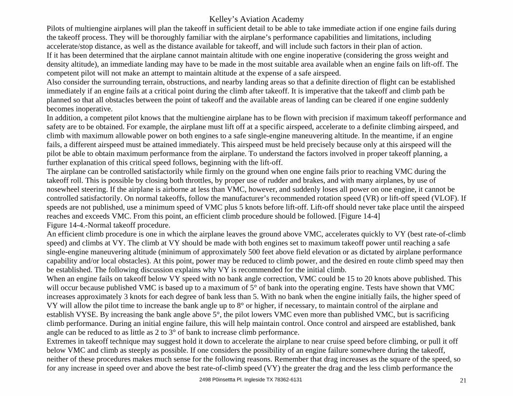
Pilots of multiengine airplanes will plan the takeoff in sufficient detail to be able to take immediate action if one engine fails during the takeoff process. They will be thoroughly familiar with the airplane’s performance capabilities and limitations, including accelerate/stop distance, as well as the distance available for takeoff, and will include such factors in their plan of action. If it has been determined that the airplane cannot maintain altitude with one engine inoperative (considering the gross weight and density altitude), an immediate landing may have to be made in the most suitable area available when an engine fails on lift-off. The competent pilot will not make an attempt to maintain altitude at the expense of a safe airspeed. Also consider the surrounding terrain, obstructions, and nearby landing areas so that a definite direction of flight can be established immediately if an engine fails at a critical point during the climb after takeoff. It is imperative that the takeoff and climb path be planned so that all obstacles between the point of takeoff and the available areas of landing can be cleared if one engine suddenly becomes inoperative. In addition, a competent pilot knows that the multiengine airplane has to be flown with precision if maximum takeoff performance and safety are to be obtained. For example, the airplane must lift off at a specific airspeed, accelerate to a definite climbing airspeed, and climb with maximum allowable power on both engines to a safe single-engine maneuvering altitude. In the meantime, if an engine fails, a different airspeed must be attained immediately. This airspeed must be held precisely because only at this airspeed will the pilot be able to obtain maximum performance from the airplane. To understand the factors involved in proper takeoff planning, a further explanation of this critical speed follows, beginning with the lift-off. The airplane can be controlled satisfactorily while firmly on the ground when one engine fails prior to reaching VMC during the takeoff roll. This is possible by closing both throttles, by proper use of rudder and brakes, and with many airplanes, by use of nosewheel steering. If the airplane is airborne at less than VMC, however, and suddenly loses all power on one engine, it cannot be controlled satisfactorily. On normal takeoffs, follow the manufacturer’s recommended rotation speed (VR) or lift-off speed (VLOF). If speeds are not published, use a minimum speed of VMC plus 5 knots before lift-off. Lift-off should never take place until the airspeed reaches and exceeds VMC. From this point, an efficient climb procedure should be followed. [Figure 14-4] Figure 14-4.-Normal takeoff procedure. An efficient climb procedure is one in which the airplane leaves the ground above VMC, accelerates quickly to VY (best rate-of-climb speed) and climbs at VY. The climb at VY should be made with both engines set to maximum takeoff power until reaching a safe single-engine maneuvering altitude (minimum of approximately 500 feet above field elevation or as dictated by airplane performance capability and/or local obstacles). At this point, power may be reduced to climb power, and the desired en route climb speed may then be established. The following discussion explains why VY is recommended for the initial climb. When an engine fails on takeoff below VY speed with no bank angle correction, VMC could be 15 to 20 knots above published. This will occur because published VMC is based up to a maximum of 5° of bank into the operating engine. Tests have shown that VMC increases approximately 3 knots for each degree of bank less than 5. With no bank when the engine initially fails, the higher speed of VY will allow the pilot time to increase the bank angle up to 8° or higher, if necessary, to maintain control of the airplane and establish VYSE. By increasing the bank angle above 5°, the pilot lowers VMC even more than published VMC, but is sacrificing climb performance. During an initial engine failure, this will help maintain control. Once control and airspeed are established, bank angle can be reduced to as little as 2 to 3° of bank to increase climb performance. Extremes in takeoff technique may suggest hold it down to accelerate the airplane to near cruise speed before climbing, or pull it off below VMC and climb as steeply as possible. If one considers the possibility of an engine failure somewhere during the takeoff, neither of these procedures makes much sense for the following reasons. Remember that drag increases as the square of the speed, so for any increase in speed over and above the best rate-of-climb speed (VY) the greater the drag and the less climb performance the

Kelley’s Aviation Academy
2498 P0insettta Pl. Ingleside TX 78362-6131 22
airplane will have. At 123 knots the drag is approximately one and one-half times greater than it is at 100 knots. At 141 knots the drag is doubled, and at 200 knots the drag is approximately four times as great as at 100 knots. While the drag is increasing as the square of the velocity (V x V), the power required to maintain a velocity increases as the cube of that velocity (V x V x V). In the event of engine failure, a pilot who uses excessive speed on takeoff will suddenly discover that all energy produced by the engines has been converted into speed. Some pilots believe that the excess speed can always be converted to altitude, but this theory is invalid. Available power is only wasted in accelerating the airplane to an unnecessary speed. Also, experience has shown that an unexpected engine failure so surprises the inexperienced pilot that proper reactions are extremely lagging. By the time the initial shock wears off and the pilot is ready to take control of the situation, the excess speed has dissipated and the airplane is still barely off the ground. From this low altitude, the pilot would still have to climb, with an engine inoperative, to whatever height is needed to clear all obstacles and return to the approach end of the runway. Excess speed cannot be converted readily to the altitude or distance necessary to reach a landing area safely. In contrast, an airplane will fly in level flight much easier than it will climb. Therefore, if the total energy of both engines is initially converted to enough height above the ground to permit clearance of all obstacles while in level flight (safe maneuvering altitude), the problem is much simpler in the event an engine fails. If some extra height is available, it can usually be traded for airspeed or gliding distance when needed. Simply stated, altitude is more essential to safety after takeoff than excess airspeed. On the other hand, trying to gain height too fast in the takeoff can also be very dangerous because of control problems. If the airplane has just become airborne and the airspeed is at or below VMC when an engine fails, the pilot could avoid a serious accident by retarding both throttles immediately. If this action is not taken immediately, the pilot will be unable to control the airplane. Consequently, the pilot should always keep one hand on the control wheel (when not operating hand controlled nose steering) and the other hand on the throttles throughout the takeoff roll. The airplane should remain on the ground until adequate speed is reached so that a smooth transition to the proper climb speed can be made. THE AIRPLANE SHOULD NEVER LEAVE THE GROUND BEFORE VMC IS REACHED. Preferably, VMC + 5 knots should be attained. If an engine fails before leaving the ground, it is advisable to discontinue the takeoff and STOP. If an engine fails after lift-off, the pilot will have to decide immediately whether to continue flight, or to close both throttles and land. However, waiting until the engine failure occurs is not the time for the pilot to plan the correct action. The action has to be planned before the airplane is taxied onto the runway. The plan of action must consider the density altitude, length of the runway, weight of the airplane, and the airplane’s accelerate/stop distance, and accelerate/go distance under these conditions. Only on the basis of these factors can the pilot decide what course to follow if an engine should fail. When the flight crew consists of two pilots, the pilot in command will brief the second pilot on what course of action will be taken should the need arise. To reach a safe single-engine maneuvering altitude as safely and quickly as possible, the climb with all engines operating has to be made at the proper airspeed. That speed should provide for: • Good control of the airplane in case an engine fails. • Quick and easy transition to the single-engine best rate-of-climb speed if one engine fails. • A fast rate of climb to attain an altitude that permits adequate time for analyzing the situation and making decisions. To make a quick and easy transition to the single-engine best rate-of-climb speed in case an engine fails, the pilot should climb at a speed greater than VYSE. If an engine fails at less than VYSE, it would be necessary for the pilot to lower the nose to increase the speed to VYSE in order to obtain the best climb performance. If the airspeed is considerably less than this speed, it might be necessary to lose valuable altitude to increase the speed to VYSE. Another factor to consider is the loss of airspeed that may occur because of

Kelley’s Aviation Academy
2498 P0insettta Pl. Ingleside TX 78362-6131 23
erratic pilot technique after a sudden, unexpected power loss. Consequently, the normal initial two-engine climb speed should not be less than VY. In summary, the initial climb speed with both engines operating should permit an attainment of a safe single-engine maneuvering altitude as quickly as possible. In the event of a sudden power loss on one engine, it should also provide time to roll 5 to 8° of bank into the operative engine for good control capabilities, identify and feather inoperative engine, and establish VYSE. The only speed that meets all of these requirements for a normal takeoff is the best rate-of-climb speed (VY) with both engines operating. ACCELERATE/STOP DISTANCE The accelerate/stop distance is the total distance required to accelerate the multiengine airplane to a specified speed, and assuming failure of an engine at the instant that speed is attained, to bring the airplane to a stop on the remaining runway. Figure 14-5.-Accelerate/stop distance. To determine accelerate/stop distance for takeoff, a pilot has to consider the runway length, field elevation, density altitude, and the airplane’s gross weight. (For simplification purposes, the following additional factors will not be discussed here: obstruction, height, headwind component, runway slope, and runway contaminants, such as rubber, soot, water, ice, and snow.) Using the chart in Figure 14-5 and with a temperature of 40 °F, a calm wind at a pressure altitude of 7,586 feet, a gross weight of 4,570 pounds, and all engines operating, the airplane being flown requires 4,400 feet to accelerate to 66 KIAS and then be brought to a stop. The most critical time for a one-engine inoperative condition in a multiengine airplane is during the 2 or 3-second period immediately following lift-off while the airplane is accelerating to climb-out speed. Although most multiengine airplanes are controllable at a speed close to the single-engine minimum control speed, the performance is often so far below optimum that continued flight following takeoff might be marginal or impossible. If one engine fails prior to reaching VMC, there is no choice but to close both throttles and bring the airplane to a stop. If engine failure occurs just after lift-off, the pilot has to decide immediately to land or to continue the takeoff and accelerate to VYSE, if that particular airplane has single-engine climb capability. To determine climb performance, a pilot has to consider the field elevation, density altitude, obstruction height, and the airplane’s gross weight. Climb performance is based on conditions specified on the chart in Figure 14-6. If these conditions are not met after lift-off, the airplane may not climb as depicted in the chart. In this example, using the chart in Figure 14-6 with a temperature of 50 °F, at a pressure altitude of 10,000 feet, and a gross weight of 4,570 pounds, two-engine rate of climb would be 1,200 FPM versus one-engine rate of climb of 100 FPM. If the decision is made to continue the takeoff, the airplane has to be able to gain altitude with one engine inoperative. This requires acceleration to VYSE if obstacles are not involved, or to VXSE if obstacles are a factor. At high density altitudes and at gross weight, a successful continuation of the takeoff is extremely improbable. Figure 14-6.-Climb performance. The flightpaths illustrated in Figure 14-7 indicate an area of decision. An engine failure in this area demands an immediate decision. Beyond this decision area, the airplane, within the limitations of single-engine climb performance, can usually be maneuvered to a landing at the departure airport. Figure 14-7.-Area of decision. PROPELLER FEATHERING When an engine fails in flight, the movement of the airplane through the air tends to keep the propeller rotating, much like a windmill. Since the failed engine is no longer delivering power to the propeller to produce thrust, but instead is absorbing energy to overcome
Kelley’s Aviation Academy
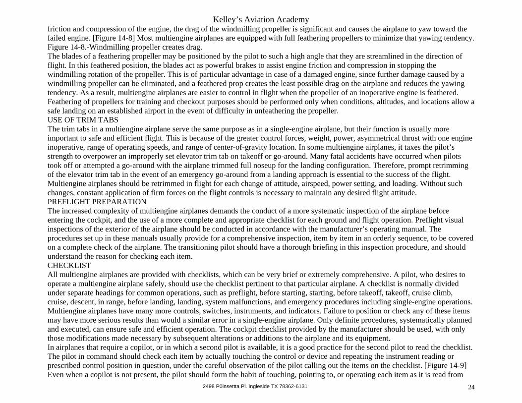
2498 P0insettta Pl. Ingleside TX 78362-6131 24
friction and compression of the engine, the drag of the windmilling propeller is significant and causes the airplane to yaw toward the failed engine. [Figure 14-8] Most multiengine airplanes are equipped with full feathering propellers to minimize that yawing tendency. Figure 14-8.-Windmilling propeller creates drag. The blades of a feathering propeller may be positioned by the pilot to such a high angle that they are streamlined in the direction of flight. In this feathered position, the blades act as powerful brakes to assist engine friction and compression in stopping the windmilling rotation of the propeller. This is of particular advantage in case of a damaged engine, since further damage caused by a windmilling propeller can be eliminated, and a feathered prop creates the least possible drag on the airplane and reduces the yawing tendency. As a result, multiengine airplanes are easier to control in flight when the propeller of an inoperative engine is feathered. Feathering of propellers for training and checkout purposes should be performed only when conditions, altitudes, and locations allow a safe landing on an established airport in the event of difficulty in unfeathering the propeller. USE OF TRIM TABS The trim tabs in a multiengine airplane serve the same purpose as in a single-engine airplane, but their function is usually more important to safe and efficient flight. This is because of the greater control forces, weight, power, asymmetrical thrust with one engine inoperative, range of operating speeds, and range of center-of-gravity location. In some multiengine airplanes, it taxes the pilot’s strength to overpower an improperly set elevator trim tab on takeoff or go-around. Many fatal accidents have occurred when pilots took off or attempted a go-around with the airplane trimmed full noseup for the landing configuration. Therefore, prompt retrimming of the elevator trim tab in the event of an emergency go-around from a landing approach is essential to the success of the flight. Multiengine airplanes should be retrimmed in flight for each change of attitude, airspeed, power setting, and loading. Without such changes, constant application of firm forces on the flight controls is necessary to maintain any desired flight attitude. PREFLIGHT PREPARATION The increased complexity of multiengine airplanes demands the conduct of a more systematic inspection of the airplane before entering the cockpit, and the use of a more complete and appropriate checklist for each ground and flight operation. Preflight visual inspections of the exterior of the airplane should be conducted in accordance with the manufacturer’s operating manual. The procedures set up in these manuals usually provide for a comprehensive inspection, item by item in an orderly sequence, to be covered on a complete check of the airplane. The transitioning pilot should have a thorough briefing in this inspection procedure, and should understand the reason for checking each item. CHECKLIST All multiengine airplanes are provided with checklists, which can be very brief or extremely comprehensive. A pilot, who desires to operate a multiengine airplane safely, should use the checklist pertinent to that particular airplane. A checklist is normally divided under separate headings for common operations, such as preflight, before starting, starting, before takeoff, takeoff, cruise climb, cruise, descent, in range, before landing, landing, system malfunctions, and emergency procedures including single-engine operations. Multiengine airplanes have many more controls, switches, instruments, and indicators. Failure to position or check any of these items may have more serious results than would a similar error in a single-engine airplane. Only definite procedures, systematically planned and executed, can ensure safe and efficient operation. The cockpit checklist provided by the manufacturer should be used, with only those modifications made necessary by subsequent alterations or additions to the airplane and its equipment. In airplanes that require a copilot, or in which a second pilot is available, it is a good practice for the second pilot to read the checklist. The pilot in command should check each item by actually touching the control or device and repeating the instrument reading or prescribed control position in question, under the careful observation of the pilot calling out the items on the checklist. [Figure 14-9] Even when a copilot is not present, the pilot should form the habit of touching, pointing to, or operating each item as it is read from

Kelley’s Aviation Academy
2498 P0insettta Pl. Ingleside TX 78362-6131 25
the checklist. In the event of an inflight emergency, the pilot should be sufficiently familiar with emergency procedures to instinctively take immediate action to prevent more serious situations. However, as soon as circumstances permit, the emergency checklist should be reviewed to ensure that all required items have been checked. Figure 14-9.-Teamwork in a multiengine airplane. TAXIING Although ground operation of multiengine airplanes may differ in some respects from the operation of single-engine airplanes, the taxiing procedures also vary somewhat between those airplanes with a nosewheel and those with a tailwheel-type landing gear. With either of these landing gear arrangements, the difference in taxiing multiengine airplanes that is most obvious to a transitioning pilot is the capability of using power differential between individual engines to assist in directional control. Tailwheel-type multiengine airplanes are usually equipped with tailwheel locks that can be used to advantage for taxiing in a straight line especially in a crosswind. The tendency to weathervane can also be neutralized to a great extent in these airplanes by using more power on the upwind engine, with the tailwheel lock engaged and the brakes used as necessary. On nosewheel-type multiengine airplanes, the brakes and throttles are mainly used to control the momentum, and steering is done principally with the steerable nosewheel. The steerable nosewheel is usually actuated by the rudder pedals, or in some airplanes by a separate hand operated steering mechanism. No airplane should be pivoted on one wheel when making sharp turns because this can damage the landing gear, tires, and even the airport pavement. All turns should be made with the inside wheel rolling, even if only slightly. Brakes may be used to start and stop turns while taxiing. When initiating a turn, the brakes should be used cautiously to prevent overcontrolling the turn. Brakes should be used as lightly as practicable while taxiing to prevent undue wear and heating of the brakes and wheels, and possible loss of ground control. When brakes are used repeatedly or constantly, they tend to heat to the point that they may either lock or fail completely. Also, tires may be weakened or blown out by extremely hot brakes. Abrupt use of brakes in multiengine, as well as single-engine airplanes is evidence of poor pilot technique; it not only abuses the airplane, but may even result in loss of control. Due to the greater weight of multiengine airplanes, effective braking is particularly essential. Therefore, as the airplane begins to move forward when taxiing is started, the brakes should be tested immediately by depressing each brake pedal. If the brakes are weak, taxiing should be discontinued and the engines shut down. Looking outside the cockpit while taxiing becomes more important in multiengine airplanes. Since these airplanes are usually somewhat heavier, larger, and more powerful than single-engine airplanes, they often require more time and distance to accelerate or stop, and provide a different perspective for the pilot. While it is usually not necessary to make S-turns to observe the taxiing path, additional vigilance is necessary to avoid obstacles, other aircraft, or bystanders. NORMAL TAKEOFFS There is virtually little difference between a takeoff in a multiengine airplane and one in a single-engine airplane. The controls of each class of airplane are operated the same; the multiple throttles of the multiengine airplane normally are treated as one compact power control and can be operated simultaneously with one hand. In the interest of safety, it is important that the pilot have a plan of action to cope with engine failure during takeoff. In a multi-pilot crew, the flying pilot should brief the crew on his or her plan of action for normal and abnormal procedures and their individual responsibilities. This briefing consists of at least the following: minimum control speed (VMC), rotation speed (VR), lift-off speed (VLOF), single-engine best rate-of-climb speed (VYSE), all-engine best rate-of-climb speed (VY), and what procedures will be
Kelley’s Aviation Academy
2498 P0insettta Pl. Ingleside TX 78362-6131 26
followed if an engine failure occurs prior to VMC and after VMC. The multiengine pilot’s primary concern on all takeoffs is the attainment of the single-engine minimum control speed plus 5 knots prior to lift-off. Until this speed is achieved, directional control of the airplane in flight may be impossible after the failure of an engine, unless power is reduced immediately on the operating engine. If an engine fails before the single-engine minimum control speed is attained, THE PILOT HAS NO CHOICE BUT TO CLOSE BOTH THROTTLES, ABANDON THE TAKEOFF, AND DIRECT COMPLETE ATTENTION TO BRINGING THE AIRPLANE TO A SAFE STOP ON THE GROUND. The multiengine pilot’s second concern on takeoff is the attainment of the best rate-of-climb speed (VY) in the least amount of time. This is the airspeed that will provide the greatest rate of climb with both engines operating. In the event of an engine failure, the single-engine best rate-of-climb speed must be held. This will provide the best rate of climb when operating with one engine inoperative and propeller feathered (if possible), or the slowest rate of descent with the proper bank angle toward the operating engine. When takeoff is made over obstructions, the best angle-of-climb speed should be maintained until the obstacles are passed then the best rate of climb maintained. The single-engine minimum control speed and the single-engine best rate-of-climb speed are published in the Airplane Flight Manual (AFM) and/or Pilot’s Operating Handbook (POH). If the crew consists of two pilots, the flying pilot will brief the other pilot on takeoff procedures prior to takeoff. Otherwise, a single pilot operator should mentally review the emergency procedures before takeoff. After runup and the “Before Takeoff” checks have been completed, the airplane should be taxied into takeoff position and aligned with the runway. If the airplanes is a tailwheel-type, the tailwheel lock (if installed) should be engaged only after the airplane has been allowed to roll straight a few feet along the intended takeoff path to center the tailwheel. Next, both throttles should be advanced simultaneously to takeoff power, and directional control maintained by the use of the steerable nosewheel and the rudder. Brakes should be used for directional control only during the initial portion of the takeoff roll when the rudder and steerable nosewheel are ineffective. During the initial takeoff roll, the engine instruments should be monitored. As the takeoff progresses, flight controls should be used, as necessary, to compensate for wind conditions. Follow the manufacturer’s recommended rotation speed (VR) or lift-off speed (VLOF). If speeds are not published, use a minimum speed of VMC plus 5 knots before lift-off. After lift-off, the airplane should be allowed to accelerate to the all-engine best rate-of-climb speed (VY). If an engine should fail, the airplane will immediately lose airspeed and this will allow a buffer between VYSE and VY. The landing gear may be raised as soon as practicable with a positive rate of climb, but not before reaching the point from which a safe landing can no longer be made on the remaining portion of the runway. The flaps (if used) should be retracted as directed in the AFM/POH. CROSSWIND TAKEOFFS Crosswind takeoffs are performed in multiengine airplanes in basically the same manner as those in single-engine airplanes. During the initial takeoff roll, less power may be used on the downwind engine to overcome the tendency of the airplane to weathervane. Full power should be applied to both engines as the airplane accelerates to a speed where rudder control is effective. The airplane should accelerate to a slightly higher-than-normal takeoff speed, and then a positive lift-off should be made to prevent possible settling back to the runway while drifting. When clear of the ground, a coordinated turn should be made into the wind to correct for drift. SHORT-FIELD OR OBSTACLE CLEARANCE TAKEOFF If it is necessary to take off over an obstacle or from a short field, the procedures should be altered slightly. For example, the initial climb speed that should provide the best angle of climb for obstacle clearance is VX rather than VY. However, VX in some multiengine airplanes is below VMC. In this case, if the climb were made at VX and a sudden power failure occurred on one engine,
Kelley’s Aviation Academy
2498 P0insettta Pl. Ingleside TX 78362-6131 27
the pilot would not be able to control the airplane unless power were reduced on the operating engine. This would create an impossible situation because it would not be likely that the airplane could clear an obstacle with one engine inoperative and the other at some reduced power setting. In any case, if an engine fails and the climb is to be continued over an obstacle, VXSE must be established if maximum performance is to be obtained. Generally, the short-field or obstacle clearance takeoff will be much the same as a normal takeoff using the manufacturer’s recommended flap settings, power settings, and speeds. However, if the published best angle-of-climb speed (VX) is less than VMC + 5, then it is recommended that no less than VMC + 5 be used. During the takeoff roll as the airspeed reaches the best angle-of-climb speed, or VMC + 5, whichever is higher, the airplane should be rotated to establish a pitch attitude that will cause the airplane to lift off and climb at that specified speed. At an altitude of approximately 50 feet or after clearing the obstacle, the pitch attitude can be lowered gradually to allow the airspeed to increase to the all-engine best rate-of-climb speed. Upon reaching safe maneuvering altitude, the airplane should be allowed to accelerate to normal or en route climb speed and the power controls reduced to the normal climb power settings. STALLS As with single-engine airplanes, the pilot should be familiar with the stall and minimum controllability characteristics of the multiengine airplane being flown. The larger and heavier airplanes have slower responses in stall recoveries and in maneuvering at slow speeds due to their greater weight. The practice of stalls in multiengine airplanes should be performed at altitudes sufficiently high to allow recoveries to be completed at least 3,000 feet above the ground or as recommended by the manufacturer. It usually is inadvisable to execute stalls in multiengine airplanes because of their relatively high wing loading; therefore, practice should be limited to approaches to stalls with recoveries initiated at the first physical indication of an approaching stall. As a general rule, stalls in multiengine airplanes are not necessarily violent or hazardous. The pilot should become familiar with approaching stalls entered with various flap settings, power settings, landing gear positions, and bank angles. It should be noted that the extension of the landing gear will cause little difference in the stalling speed, but it will cause a more rapid loss of speed in approaching to a stall. For power-off stalls, the airplane can be configured for landing. After a rate of descent is established that is consistent with landing, power should be reduced to or near idle. This usually results in a level attitude stall. Power-on stalls should be entered with both engines set at approximately 65 percent power. Takeoff power may be used after slowing to lift-off airspeed. Stalls in airplanes with relative low power loading using maximum climb power usually result in an excessive nose-high attitude and make the recovery more difficult. Because of possible loss of control, stalls with one engine inoperative or at idle power and the other engine developing effective power, should not be practiced by applicants for multiengine class ratings. The same procedures used in the recognition and avoidance of stalls of single-engine airplanes apply to stalls in multiengine airplanes. The transitioning pilot has to be familiar with the characteristics that announce an approaching stall, the indicated airspeed at which it occurs, and the proper procedure for recovery. The increase in pitch attitude for stall entries should be gradual to prevent momentum from carrying the airplane into an abnormally high noseup attitude with a resulting deceptively low indicated airspeed at the time the stall occurs. It is recommended that the rate-of-pitch change result in a 1-knot-per second decrease in airspeed. In all stall recoveries, the controls should be used very smoothly, avoiding abrupt pitch changes. Because of high gyroscopic stresses, this is particularly true in airplanes with extensions between the engines and propellers. EMERGENCY DESCENT When it is necessary to descend as rapidly as feasible, such as in the case of an inflight fire, follow the manufacturer’s recommended
Kelley’s Aviation Academy
2498 P0insettta Pl. Ingleside TX 78362-6131 28
procedures. When specific procedures are not published, the following procedures may be used and modified, as required. 1. Props Max RPM 2. Throttles Closed 3. Airspeed Max Gear Down Speed or Max Flap Approach Speed (whichever is lower) 4. Landing Gear Down 5. Flaps Approach The maneuvering speed (VA) may be used as descent airspeed but should not be higher than maximum gear down speed or flap approach speed if flaps are used. During practice emergency descents, careful consideration should be given to the operating temperature of the engines. Rapid descents with throttles closed will cause the engines to cool rapidly and possibly cause cylinder damage. In practice, some power should be left on to prevent the engines from cooling rapidly. Figure 14-10.-Normal two-engine approach and landing. APPROACHES AND LANDINGS Multiengine airplanes characteristically have steeper gliding angles because of their relatively high wing loading, and greater drag of wing flaps and landing gear when extended. For this reason, power is normally used throughout the approach to shallow the approach angle and prevent a high rate of sink. The accepted procedure for making stabilized landing approaches is to reduce the power to a predetermined setting during the arrival descent, so the appropriate landing gear extension speed will be attained in level flight as the downwind leg of the approach pattern is entered. [Figure 14-10] With this power setting, the extension of the landing gear will further reduce the airspeed to the desired traffic pattern airspeed. The manufacturer’s recommended speed should be used throughout the pattern. When practicable, the speed should be compatible with other air traffic in the traffic pattern. When within the maximum speed for flap extension, the flaps may be partially lowered, if desired, to aid in reducing the airspeed to traffic pattern speed. The angle of bank should normally not exceed 30° while turning onto the legs of the traffic pattern. The landing checklist should be completed by the time the airplane is on base leg so that the pilot may direct full attention to the approach and landing. In a power approach, the airplane should descend at a stabilized rate, allowing the pilot to plan and control the approach path to the point of touchdown. Further extension of the flaps and slight adjustment of power and pitch should be accomplished, as necessary, to establish and maintain a stabilized approach path. Power and pitch changes during approaches should in all cases, be smooth and gradual. The airspeed of the final approach should be as recommended by the manufacturer. If a recommended speed is not furnished, the airspeed should not be less than the single-engine best rate-of-climb speed (VYSE) until the landing is assured. This is the minimum speed a single-engine go-around can be made if necessary. IN NO CASE SHOULD THE APPROACH SPEED BE LESS THAN THE CRITICAL ENGINE INOPERATIVE MINIMUM CONTROL SPEED. If an engine should fail suddenly and it is necessary to make a go-around from a final approach at less than this speed, a loss of control could occur. As a rule of thumb, after the wing flaps are extended the final approach speed should be gradually reduced to 1.3 times the power-off stalling speed (1.3 VSO). The roundout or flare should be started at a sufficient altitude to allow a smooth transition from the approach to the landing attitude. The touchdown should be smooth, with the airplane touching down on the main wheels and in a tail-low attitude, with or without power as desired. Although airplanes with nosewheels should touch down in a tail-low attitude, it should not be so low as to drag the tail on the runway. On the other hand, since the nosewheel is not designed to absorb the impact of the full weight of the airplane, level or nose-low attitudes must be avoided. Directional control on the rollout should be accomplished primarily with the rudder and the steerable nosewheel, with discrete use of

Kelley’s Aviation Academy
2498 P0insettta Pl. Ingleside TX 78362-6131 29
the brakes applied only as necessary for crosswinds or other factors. CROSSWIND LANDINGS Crosswind landing procedures in multiengine airplanes are similar to those in single-engine airplanes. The only significant difference lies in the fact that because of the greater weight, more positive drift correction must be maintained before the touchdown. The two basic methods of making crosswind landings, the slipping approach (wing low) and the crabbing approach, may be combined. These are discussed in the chapter on Approaches and Landings. The essential factor in all crosswind landing procedures is touching down without drift, with the heading of the airplane parallel to its direction of motion. This will result in minimum side loads on the landing gear. SHORT-FIELD LANDING Short-field landing procedures are similar to those in a normal approach and landing. Approach with full flaps at the recommended short-field approach speed. If a recommended speed is not furnished, after landing is assured and the wing flaps are extended, a rule of thumb is 1.2 x VSO, but not less than VMC for safety. Immediately after touchdown, raise the flaps, apply the back-elevator pressure and apply brakes. GO-AROUND PROCEDURE The complexity of multiengine airplanes makes a knowledge of and proficiency in emergency go-around procedures particularly essential for safe piloting. The emergency go-around during a landing approach is inherently critical because it is usually initiated at a very low altitude and airspeed with the airplane’s configuration and trim adjustments set for landing. Unless absolutely necessary, the decision to go around should not be delayed to the point where the airplane is ready to touch down. [Figure 14-11] The more altitude and time available to apply power, establish a climb, retrim, and set up a go-around configuration, the easier and safer the maneuver becomes. When the pilot has decided to go around, immediate action should be taken without hesitation, while maintaining positive control and accurately following the manufacturer’s recommended procedures. Figure 14-11.-Make a timely decision to go around or land. Go-around procedures vary with different airplanes, depending on their weight, flight characteristics, flap and retractable gear systems, and flight performance. Specific procedures must be learned by the transitioning pilot from the AFM/POH, which should always be available in the cockpit. There are several general go-around procedures that apply to most airplanes. • When the decision to go around is reached, takeoff power should be applied immediately and the descent stopped by adjusting the pitch attitude to avoid further loss of altitude. • The flaps should be retracted in accordance with the procedure prescribed in the AFM/POH. • After a positive rate of climb is established, the landing gear should be retracted, best rate-of-climb airspeed (VY) obtained and maintained, and the airplane trimmed for this climb. Any remaining flaps are then retracted. The procedure for a normal takeoff climb should then be followed. At any time the airspeed is faster than the flaps-up stalling speed, the flaps may be retracted completely without losing altitude if simultaneously the angle of attack is increased sufficiently. At slow airspeeds, retracting the flaps prematurely or suddenly can cause a stall or an unanticipated loss of altitude. Rapid or premature retraction of the flaps should be avoided on go-arounds, especially when close to the ground, because of the careful attention and exercise of precise pilot technique necessary to prevent a sudden loss of altitude. Generally, retracting the flaps only halfway or to the specified approach setting decreases the drag a relatively greater amount than it decreases the lift. The AFM/POH should be consulted regarding landing gear and flap retraction procedures. In some installations, simultaneous
Kelley’s Aviation Academy
2498 P0insettta Pl. Ingleside TX 78362-6131 30
retraction of the gear and flaps may increase the flap retraction time, and full flaps create more drag than the extended landing gear. ENGINE INOPERATIVE EMERGENCIES The operating and flight characteristics of multiengine airplanes with one engine inoperative are excellent. Multiengine airplanes can be controlled and maneuvered safely as long as sufficient airspeed is maintained. However, to utilize the safety and performance characteristics effectively, the pilot has to have a sound understanding of the single-engine performance and the limitations resulting from an unbalance of power. A pilot checking out for the first time in any multiengine airplane should practice and become thoroughly familiar with the control and performance problems that result from the failure of one engine during any flight condition. Practice should be continued as long as the pilot engages in flying a multiengine airplane so that corrective action will be instinctive, and the ability to control airspeed, heading, and altitude will be retained. The feathering of a propeller should be demonstrated and practiced during training in all airplanes equipped with propellers that can be feathered and unfeathered safely in flight. If the airplane used is not equipped with feathering propellers, one engine should be secured (shut down) in accordance with the procedures in the AFM/POH. All training in multiengine airplanes involving engine shut down, regardless if the propeller can be feathered or not, must be accomplished at an altitude that will allow for a safe landing at an established airport if an actual emergency develops. ENGINE INOPERATIVE PROCEDURES The following procedures are recommended to develop in the transitioning pilot the habit of using proper procedures and proficiency in coping with an inoperative engine. At a safe altitude (minimum 3,000 feet above terrain) and within landing distance of a suitable airport, an engine may be shut down with the mixture control or fuel selector. At lower altitudes, however, shut down should be simulated by reducing power by adjusting the throttle to the zero thrust setting. The following procedures should then be followed: 1. Fly the airplane Maintain control, VYSE, heading, bank into operating engine. 2. Power Increase or leave as set for takeoff. 3. Drag (reduce) Props, gear, or flaps-pilots choice based on conditions and airplane. 4. Identify Idle foot inoperative engine. 5. Verify With throttle or other means. 6. Feather Inoperative engine propeller. 7. Checklist Start from the top. In all cases, the airplane manufacturer’s recommended procedure for single-engine operation should be followed. The general procedures listed above are not intended to replace or conflict with any procedure established by the manufacturer of any airplane. It can be used effectively for general training purposes and to emphasize the importance of maintaining aircraft control and reducing drag. The pilot must be proficient in the control of heading, airspeed, and altitude; in the prompt identification of a power failure; and in the accuracy of shutdown and restart procedures as prescribed in the AFM/POH. There is not a better way to develop skill in single-engine emergencies than by continued practice. The fact that the procedures of single-engine operation are mastered thoroughly at one time during a pilot’s career is no assurance of being able to cope successfully with a single-engine emergency unless review and practice are continued. Some engine inoperative emergencies may be so critical that there may not be a safety margin for lack of skill or knowledge. It is essential that the multiengine pilot take proficiency training periodically from a competent flight instructor.

Kelley’s Aviation Academy
2498 P0insettta Pl. Ingleside TX 78362-6131 31
The pilot should practice and demonstrate the effects (on single-engine performance) of various configurations of gear, flaps, and both; the use of carburetor heat; and the failure to feather the propeller on an inoperative engine. Each configuration should be maintained at single-engine best rate-of-climb speed long enough to determine its effect on the climb (or sink) achieved. Prolonged use of carburetor heat, if equipped, at high-power settings should be avoided. VMC DEMONSTRATIONS Every multiengine airplane checkout should include a demonstration of the airplane’s single-engine minimum control speed. The single-engine minimum control speed given in the AFM/POH or other manufacturer’s published limitations is determined during the original airplane certification under conditions specified in the CFR’s. These conditions are normally not duplicated during pilot training or testing because they consist of the most adverse situations for airplane-type certification purposes. Prior to a pilot checkout, a thorough discussion of the factors affecting single-engine minimum control speed is essential. The VMC demonstrations should be performed at an altitude that will allow the maneuver to be completed no lower than 3,000 feet above ground level (AGL) or the manufacturer’s recommended altitude, whichever is higher. One demonstration should be made while holding the wings level and the ball centered, and another demonstration should be made while banking the airplane at least 5° toward the operating engine to establish zero sideslip. These maneuvers will demonstrate the single-engine minimum control speed for the existing conditions and will emphasize the necessity of banking into the operative engine. An attempt should not be made to duplicate VMC, as determined for airplane certification. After the propellers are set to high revolutions per minute (RPM), the landing gear is retracted, and the flaps are in the takeoff position, the airplane should be placed in a climb attitude and an airspeed at or above the intentional one-engine inoperative speed (VSSE). With both engines developing as near rated takeoff power as possible, power on the critical engine (usually the left) should then be reduced to idle (windmilling, not shut down). After this is accomplished, the airspeed should be reduced at approximately 1 knot per second with the elevators until directional control can no longer be maintained. At this point, recovery should be initiated by simultaneously reducing power sufficiently on the operating engine and reducing the angle of attack by lowering the nose of the airplane to accelerate to VSSE. Under no circumstances should an attempt be made to fly at a speed below VMC with only one engine operating. Should indications of a stall occur prior to reaching this point, recovery should be initiated immediately by reducing the angle of attack and power on the operating engine to control roll and increase airspeed to VSSE. The demonstration should then be accomplished with the rudder travel limited at a higher airspeed. ENGINE FAILURE BEFORE LIFT-OFF (REJECTED TAKEOFF) When an engine fails during the takeoff roll before becoming airborne, it is advisable to close both throttles immediately and employ maximum braking, while maintaining directional control. In training, the recommended procedure to simulate an engine failure on takeoff is to close the mixture on one engine before 50 percent VMC. This provides a safety factor for the instructor pilot and more time for the training pilot to make a proper decision. If the training pilot fails to recognize the emergency promptly, the instructor pilot can close the mixture on the running engine and bring the airplane safely to a stop. Also, during training, to save wear and tear on the airplane, the training pilot may announce maximum braking rather than actually using maximum braking when remaining runway length is adequate. ENGINE FAILURE AFTER LIFT-OFF If after becoming airborne an engine should fail prior to having reached the single-engine best rate-of-climb speed (VYSE), the same procedure used for engine failure before lift-off should be followed. This is recommended because an immediate landing is usually inevitable because of the altitude loss required to increase the speed to VYSE. The pilot must have determined before takeoff what altitude, airspeed, and airplane configuration must exist to permit the flight to

Kelley’s Aviation Academy
2498 P0insettta Pl. Ingleside TX 78362-6131 32
continue in the event of an engine failure. The pilot should also be ready to accept the fact that if engine failure occurs before these required factors are established, both throttles must be closed and the situation treated the same as an engine failure on a single-engine airplane. If it has been predetermined that the single-engine rate of climb under existing circumstances will be at least 50 FPM at 1,000 feet above the airport, and that at least the single-engine best angle-of-climb speed has been attained, the pilot may decide to continue the takeoff. If the airspeed is below the single-engine best angle-of-climb speed (VXSE) and the landing gear has not been retracted, the takeoff should be abandoned immediately. Figure 14-12.-Engine failure during takeoff procedures. If the single-engine best angle-of-climb speed (VXSE) has been obtained and the landing gear is in the retract cycle, the pilot should climb at the single-engine best angle-of-climb speed (VXSE) to clear any obstructions. The pilot should hold 5 to 8° of bank into the operating engine and stabilize the airspeed at the single-engine best rate-of-climb speed (VYSE) while identifying, verifying, and feathering the inoperative engine propeller, then, retract the flaps. When the decision is made to continue the flight, the single-engine best rate-of-climb speed should be attained and maintained with the inoperative engine feathered. [Figure 14-12] Even if altitude cannot be maintained, it is best to continue to hold that speed because it would result in the slowest rate of descent and provide the most time for executing the emergency landing. After the decision is made to continue flight and a positive rate of climb is attained, the landing gear should be retracted as soon as practical. If the airplane is barely able to maintain altitude and airspeed, a turn requiring a bank greater than 15° should not be attempted. When such a turn is made under these conditions, both lift and airspeed will decrease. It is advisable to continue straight ahead whenever possible, until reaching a safe maneuvering altitude and VYSE. At that time, a steeper bank may be made safely in either direction. There is nothing wrong with banking toward a “inoperative” engine if a safe speed and zero sideslip are maintained. When an engine fails after becoming airborne, the pilot should hold the heading with the rudder and simultaneously roll into a bank of 5 to 8° toward the operating engine. The more bank used initially will lower VMC and help maintain control with no or very little climb performance. With the airplane under control and the proper airspeed attained for climb, the bank angle can be reduced to establish zero slip to increase climb performance. Without a yaw indicator, 2° to 3° of bank and one-half ball deflection is recommended for maximum performance. The best way to identify the inoperative engine is to note the direction of yaw and the rudder pressure required to maintain heading. To counteract the asymmetrical thrust, extra rudder pressure will have to be exerted on the operating engine side. To aid in identifying the failed engine, some pilots use the expression “Dead Foot Dead Engine.” Never rely on tachometer or manifold pressure readings to determine which engine has failed. After power has been lost on an engine, the tachometer will often indicate the correct RPM and the manifold pressure gauge will indicate the approximate atmospheric pressure or above. Experience has shown that the biggest problem is not in identifying the inoperative engine, but rather in the pilot’s actions after the inoperative engine has been identified. In other words, a pilot may identify the inoperative engine and then attempt to shut down the wrong one, resulting in no power at all. To avoid this mistake, the pilot should verify that the inoperative engine has been identified by retarding the throttle of the suspected engine before shutting it down. When demonstrating or practicing procedures for engine failure on takeoff, the feathering of the propeller and securing of the engine should be simulated rather than actually performed, so that the engine may be available for immediate use if needed. All other settings should be made just as in an actual power failure. ENGINE FAILURE EN ROUTE Normally, when an engine failure occurs while en route in cruising flight, the situation is not as critical as when an engine fails on takeoff. With the more leisurely circumstances, the pilot should take time to determine the cause of the failure and to correct the

Kelley’s Aviation Academy
2498 P0insettta Pl. Ingleside TX 78362-6131 33
condition, if possible. If the condition cannot be corrected, the single-engine procedure recommended by the manufacturer should be accomplished and a landing made as soon as practical. A primary error during engine failure is the pilot’s tendency to perform the engine inoperative identification and shutdown too quickly, resulting in improper identification or incorrect shutdown procedures. The element of surprise generally associated with actual engine failure may result in confused and hasty reactions. When an engine fails during cruising flight, the pilot’s main problem is to maintain sufficient altitude to be able to continue flight to the nearest suitable point of landing. This is dependent on the density altitude, gross weight of the airplane, and elevation of the terrain and obstructions. When the airplane is above its single-engine service ceiling, altitude will be lost. The single-engine service ceiling is the maximum density altitude at which the single-engine best rate-of-climb speed will produce 50 FPM rate of climb. This ceiling is determined by the manufacturer on the basis of the airplane’s maximum gross weight, flaps and landing gear retracted, the critical engine inoperative, and the propeller feathered. Although engine failure while en route in normal cruise conditions may not be critical, it is a recommended practice to add maximum available power to the operating engine before securing or shutting down the failed engine. If it is determined later that maximum available power on the operating engine is not needed to maintain altitude, it is a simple matter to reduce the power. Conversely, if maximum available power is not applied, the airspeed may decrease much farther and more rapidly than expected. This condition could present a serious performance problem, especially if the airspeed should drop below VYSE. The altitude should be maintained if it is within the capability of the airplane. If the airplane is not capable of maintaining altitude with an engine inoperative under existing circumstances, the airspeed should be maintained at the single-engine best rate-of-climb speed (VYSE) so as to conserve altitude as long as possible to reach a suitable landing area. After the failed engine is shut down and everything is under control (including heading and altitude), it is recommended that the pilot communicate with the nearest ground facility to let them know the flight is being conducted with one engine inoperative. Federal Aviation Administration (FAA) facilities are able to give valuable assistance if needed, particularly when the flight is conducted under instrument flight rules (IFR) or a landing is to be made at a tower controlled airport. Good judgment dictates that a landing be made at the nearest suitable airport rather than continuing flight. During single-engine practice using zero thrust power settings, the engine may cool to temperatures considerably below the normal operating range. This factor requires caution when advancing the power at the termination of single-engine practice. If the power is advanced rapidly, the engine may not respond and an actual engine failure may be encountered. This is particularly important when practicing single-engine approaches and landings. A good procedure is to slowly advance the throttle to approximately one-half power, then allow it to respond and stabilize before advancing to higher power settings. This procedure also results in less wear on the engines. Restarts after feathering require the same amount of care, primarily to avoid engine damage. Following the restart, the engine power should be maintained at the idle setting or slightly above until the engine is sufficiently warm and is receiving adequate lubrication. ENGINE INOPERATIVE APPROACH AND LANDING Essentially, a single-engine approach and landing is the same as a normal approach and landing. Long, flat approaches with high-power output on the operating engine and/or excessive threshold speed that results in floating and unnecessary runway use should be avoided. Due to variations in the performance and limitations of many multiengine airplanes, a specific flightpath or procedure can not be proposed that would be adequate in all single-engine approaches. In most multiengine airplanes, a single-engine approach can be accomplished with the flightpath and procedures almost identical to a normal approach and landing. The multiengine manufacturers include a recommended single-engine landing procedure in the AFM/POH.
Kelley’s Aviation Academy
2498 P0insettta Pl. Ingleside TX 78362-6131 34
During the checkout, the transitioning pilot should perform approaches and landings with the power of one engine set to simulate the drag of a feathered propeller (zero thrust), or if feathering propellers are not installed, the throttle of the simulated failed engine set to idle. With the inoperative engine feathered or set to zero thrust, normal drag is considerably reduced, resulting in a longer landing roll. Allowances should be made accordingly for the final approach and landing. The final approach speed should not be less than VYSE until the landing is assured; thereafter, it should be at the speed commensurate with the flap position until beginning the roundout for landing. Under normal conditions, the approach should be made with full flaps; however, neither full flaps nor the landing gear should be extended until the landing is assured. When more drag is required, the landing gear should be the first option if it does not conflict with the manufacturer’s recommended procedure. With full flaps, the approach speed should be 1.3 VSO or as recommended by the manufacturer. The pilot should be particularly judicious in lowering the flaps. Once they have been extended, it may not be possible to retract them in time to initiate a go-around. Most of the multiengine airplanes are not capable of making a single-engine go-around with full flaps. Each make and model of airplane must be operated in accordance with the manufacturer’s recommended procedures.