kelly and boyce
TRANSCRIPT
8/10/2019 Kelly and Boyce
http://slidepdf.com/reader/full/kelly-and-boyce 1/43
1
A Practical Guide to ‘Free Energy’ Devices
Devices Part 9: Created: 12th June 2005. Last updated: 24th September 2007 Author: Patrick J. Kelly
This document provides practical information on the construction of different types of electrolysers. Thisdocument is for information purposes only and should not be interpreted as encouragement to actually
physically construct any of these devices. The gas produced by electrolysis is very dangerous and shouldyou decide to experiment with it, you do so wholly at your own risk. The author of this document stressesthat he is not recommending that you build any of these devices and he disclaims any responsibilitywhatsoever should you decide to do so against his advice.
What is an Electrolyser?
An ‘electrolyser’ is a cell which breaks water down into hydrogen and oxygen gasses by passing an electriccurrent through the water. The resulting gas is called ‘hydroxy’ gas, as it is a mixture of hydrogen andoxygen. Hydroxy gas is highly explosive, much more so than hydrogen on its own, and very much moredangerous than petrol vapour, burning at least 1,000 times faster. The slightest spark will set it off andexploding as little as a single cupful of hydroxy gas produces a bang so loud that it can cause permanenthearing damage.
Consequently, the most important information about electrolysers concerns the safety devices andtechniques which must be used with them. The objectives are to keep the amount of hydroxy gas actuallypresent in the system, to an absolute minimum, and to prevent any spark reaching the gas.
The question arises then, if these things are so dangerous, why do people want to construct them? Theanswer is that they are very useful. The output from a simple electrolyser can be mixed in with the air beingdrawn into the engine of a vehicle and the result is generally; much improved miles per gallon, muchreduced pollution emissions, and the automatic removal of carbon deposits inside the engine, promotinglonger engine life. The output from an advanced electrolyser can replace fuel oil altogether, but such anelectrolyser is difficult to build and the exhaust system will rust, and the piston rings may also rust.
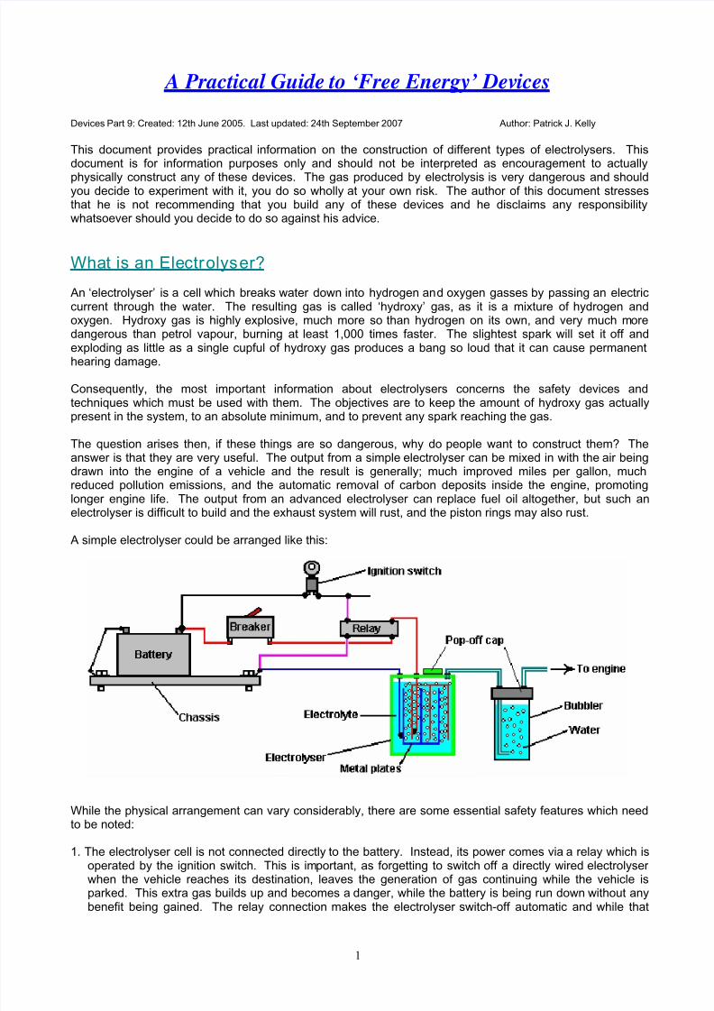
A simple electrolyser could be arranged like this:
While the physical arrangement can vary considerably, there are some essential safety features which needto be noted:
1. The electrolyser cell is not connected directly to the battery. Instead, its power comes via a relay which isoperated by the ignition switch. This is important, as forgetting to switch off a directly wired electrolyserwhen the vehicle reaches its destination, leaves the generation of gas continuing while the vehicle isparked. This extra gas builds up and becomes a danger, while the battery is being run down without anybenefit being gained. The relay connection makes the electrolyser switch-off automatic and while that
8/10/2019 Kelly and Boyce
http://slidepdf.com/reader/full/kelly-and-boyce 2/43
2
sounds like a minor thing, it most definitely is not. An even better connection for the relay is to wire itacross the electrical fuel pump as that powers down automatically if the engine stalls with the ignition on.
2. The electrical supply to the electrolyser then passes through a resettable circuit-breaker. This is also animportant feature because, should any malfunction occur in the electrolyser cell which causes acontinuously increasing current to be drawn (such as undue overheating of the cell), then the circuitbreaker disconnects the link and prevents any serious problem arising. A light-emitting diode with a
current limiting resistor of say, 680 ohms in series with it, can be wired directly across the contacts of thecircuit breaker. The Light-Emitting Diode can be mounted on the dashboard. As the contacts arenormally closed, they short-circuit the LED and so no light shows. If the circuit-breaker is tripped, thenthe LED will light up to show that the circuit-breaker has operated. The current through the LED is so lowthat the electrolyser is effectively switched off.
3. Both the electrolyser and the ’bubbler’ have tightly fitting ‘pop-off’ caps. This is very important. If thehydroxy gas above the surface of the liquid were to be ignited and the unit were robustly sealed, then thepressure build up inside the unit would be very rapid and it would explode like a grenade. If however,‘pop-off’ caps are installed, then as the pressure starts to build up, the cap is displaced, maintaining theintegrity of the unit, and preventing excessive pressure build-up. Having said that, it is a major objectiveto avoid gas ignition in the first place.
4. The wires going to the plates inside the electrolyser are both connected well below the surface of theliquid. This is to avoid the possibility of a connection working loose with the vibration of the vehicle andcausing a spark in the gas-filled region.
5. The volume above the surface of the liquid is kept as low as possible to minimise the size of an explosionin the unlikely event of one occurring in spite of all of the precautions. Some experimenters like to reducethe volume above the liquid surface by filling it with polystyrene ‘beans’. I am not happy with thatarrangement as polystyrene is a material with major electrostatic properties. Massive charges build uprapidly on polystyrene, and while the damp conditions inside the electrolyser are not particularly suitableto electrostatic sparks, I feel that the risk of explosion is greater with moving pieces of polystyrene insidethe cell.
6. Finally, the hydroxy gas is passed through a ‘bubbler’ before being fed to the engine. A bubbler is just a
tall and narrow container of water with the gas being fed into it near the bottom, and forced to rise throughthe water before continuing it’s journey to the engine. If, for any reason, the gas in the pipe feeding theengine is ignited, then the gas above the water in the bubbler will be ignited. That will blow the cap offthe bubbler, restrict the explosion to a small amount of gas, and the water column in the bubbler preventsthe gas in the electrolyser from being ignited. People have suggested using flashback arrestors fromgas-welding equipment but these are far too slow to work with hydroxy gas where the flame front movesat a thousand metres per second. So the best practice is to use one, or more, bubblers as they are easyto make and install and are very reliable.
Different Types of Electrolyser
There are three main types of electrolyser:
1. 12 Volt Single Cell.2. 12 Volt Series Cell.3. High-Voltage Series Cell.
Each of these will be covered in detail in the remainder of this document. Certain principles apply to eachtype and will be covered after the three descriptions. These include the necessary surface area of eachelectrode, the ‘conditioning’ of the electrodes and dealing with bubbles.

8/10/2019 Kelly and Boyce
http://slidepdf.com/reader/full/kelly-and-boyce 3/43
3
12 Volt Single Cells
The most simple electrolyser to construct is the single cell version as shown above. This can use any sizeand shape of container which makes is convenient for mounting in the engine compartment of the vehicle.Many people opt for a cylindrical container as these are widely available and are easier to mount, possiblyas shown here:
Finding space in the engine compartment is one of the more difficult tasks with European cars as theirdesigns tend to pack the engine area tightly to reduce the size of the vehicle to a minimum.
The rate of gas production depends on a number of factors:
1. The liquid used for electrolysis. If distilled water is used, then almost no current will flow through the cellas distilled water has a very high resistance to current flow, and almost no gas will be produced. It isnormal practice to add some other substance to the water to increase the rate of gas production.
If salt is added to the water, the rate of electrolysis increases enormously. However, that is not a goodchoice of additive as the salt forms a corrosive mixture and Chlorine gas is produced along with theHydrogen and Oxygen gasses. The same goes for battery acid; it does work but it is a very poor choicewhich causes practical problems over a period of time. Other additives will create the increase in gasproduction but have similar undesirable effects.
Two additives stand out as being the best choices. The first is Sodium Hydroxide (chemical symbolNaOH), sometimes called ‘lye’. The very best choice is Potassium Hydroxide (chemical symbol KOH)which is available in pellet form. Potassium Hydroxide acts as a catalyst in the process of electrolysis inthat it promotes the gas production but does not get used up in the process.
2. The spacing of the electrode plates. The closer together the plates are placed, the greater the rate of gasproduction. There is a practical limit to this, as bubbles of gas formed between the plates have to be ableto escape and rise to the surface. The optimum spacing is generally considered to be 3 mm or 1/8 inch,although some people prefer to have a 5 mm gap between the plates. These plates are typically madefrom 316 grade stainless steel.
3. The area of the electrode plates and the preparation of the plate surface. The greater the plate area, thegreater the rate of gas production. Some of this effect may be due to the improvement in the chances ofbubbles escaping from the plates and not blocking some of the plate area. It is recommended that eachface of every electrode plate has an area of between two and four square inches (13 and 25 squarecentimetres) per amp of current flowing through the cell.
The preparation of the surface of the plates has a major effect on the rate of gas production. A majorimprovement is achieved if both sides of each plate are sanded in a criss-cross pattern (this produces anincreased surface area with thousands of microscopic peaks which help bubbles form and leave theplate). The plates are then assembled and immersed in the electrolyte solution for about three days.This creates a protective white coating on the surface of the plates which helps enhance the electrolysis.The plates are then rinsed off with distilled water and the cell is refilled with a fresh solution of electrolyte.

8/10/2019 Kelly and Boyce
http://slidepdf.com/reader/full/kelly-and-boyce 4/43
4
4. The current flowing through the cell. This is an absolutely key factor in gas production, and one of themost difficult to control accurately and economically. The greater the current, the greater the rate of gasproduction. The current is controlled by the concentration of Potassium Hydroxide in the electrolyte(water plus KOH) and the voltage across the cell. The voltage across the cell has limited effect as itreaches a maximum at just 1.24 volts. Up to that point, an increase in voltage causes an increase in gasproduction rate. Once the voltage gets over 1.24 volts, increasing it further produces no further increase
in the rate of gas production.If the voltage is increased above 1.24 volts, the extra voltage goes to heat the electrolyte. Assume thatthe current through the cell is 10 amps. In that case, the power used to produce gas is 10 amps x 1.24volts = 12.4 watts. When the engine is running, the voltage at the battery terminals will be about 13.8volts as the alternator provides the extra voltage to drive current into the battery. The excess voltageapplied to the cell is about 1.24 less than that, say 12.5 volts. The power which heats the electrolyte isabout 12.5 volts x 10 amps = 125 watts. That is ten times the power being used to produce gas. This isvery, very inefficient. The following diagram may help you understand the situation:
The best electrode material for the plates is 316L-grade stainless steel. It is hard to believe, but there is avoltage drop across the plate, which makes it necessary to apply about 2 volts to the plates on each sideof the cell. So, if you are running off 12 volts, then six cells in a row across the battery gives themaximum possible drive. With the engine running and providing almost 14 volts, seven cells gives thehighest possible drive.
The electrolyte heating up is a wholly bad thing as it drives a good deal of water vapour out of theelectrolyte and this mixes with the gas and is fed to the engine. Injecting water mist, which is a fine sprayof water droplets, into an engine increases its performance due to the water expanding when it is heated.This improves both the engine power and the miles per gallon, and it makes the engine run cooler, whichimproves the life of the engine. But water vapour is a bad thing as it is already fully expanded and justgets in the way of the hydroxy gas, diluting it and lowering the power of the engine with no benefit at all..
As the voltage applied to the cell is pretty much fixed, the current flow is controlled by the concentration ofPotassium Hydroxide in the electrolyte and the plate area. Once the cell is built, the plate area is fixed,so the current is adjusted by controlling the amount of KOH added to the water.
There is a slight limit to this, in that the gas production increases with KOH concentration until theconcentration reaches 28% (by weight). After that point, any increase in the concentration produces areduction in the rate of gas production. General practice is to have a fairly low concentration of KOHwhich is found by trial. Bob Boyce, who is very experienced in this field, says that you should never addwater to NaOH or KOH. Always start with water, and add the chemical to the water SLOWLY, stirringwell and allowing the mixture to cool in between additions. Shelf life depends on how well it is sealedfrom the atmosphere. Carbon is an enemy to this process. Whether the KOH is in dry or liquid form, itwill absorb carbon from CO 2 in the atmosphere, or any other source of free carbon. As this happens, thecatalytic effect is diminished. The more carbon is absorbed, the less the catalytic efficiency of the

8/10/2019 Kelly and Boyce
http://slidepdf.com/reader/full/kelly-and-boyce 5/43
5
electrolyte. So, if you wish to maintain maximum performance, it is crucial to keep air out of your dry orliquid chemical storage containers, AND away from the electrolyte in your cells.
5. The temperature of the electrolyte. The hotter the electrolyte, the higher the current carried through it.This can be a snag. Suppose it is decided that the current through the cell is to be 10 amps and theelectrolyte concentration adjusted to give that current when the engine is started. As time passes, the125 watts of excess power drawn from the battery, heats the electrolyte, which in turn causes an increase
in the current flowing through the cell, which causes even greater heating, which..... The result is positivefeedback which causes a runaway temperature effect.
This effect is aggravated by the water in the cell being used up as the vehicle drives along. This raisesthe concentration of the electrolyte because the amount of KOH remains the same while the amount ofwater reduces.
There are different ways of dealing with this problem. One is to reduce the concentration of KOH so thatthe chosen current is only reached when the electrolyte has reached its maximum working temperature.This is a simple solution with the slight disadvantage that the gas production rate when starting is lowerthan it could be. However, the heating power is so high that it will not be long until the cell is operating atits maximum temperature.
A different way to handle the problem is to use an electronic circuit to limit the current through the cell tothe chosen value by dropping the voltage applied to the cell. This has the disadvantage that the extrapower is being dissipated in the electronics which then has a heat problem. Also, this solution does notimprove the overall efficiency of the process.
The best way of all is to reduce the voltage applied to the cell by using more than one cell connected in adaisy-chain across the battery. With two cells, each will get about seven volts across it and the gasproduction will be doubled. If space in the engine compartment allows, a chain of six cells can be usedwhich means each receives about two volts and the waste powers is reduced to some 10.6 watts per cell,while the gas production is six times higher. With the higher rate of gas production, it would probably bepossible to reduce the chosen current flowing through the cell. Also, with six cells, the amount of water issix times greater and so there will be less concentrating of the electrolyte due to the water being used up.This is a “Series-Cell” arrangement.
6. The number of bubbles sticking to the surface of the electrode plates. This is generally considered to be asignificant problem. Many methods have been used to deal with it. Some people use magnets, otherspump the electrolyte around to dislodge the bubbles, others use buzzers to vibrate the plates and somepulse the voltage to the cell at just the right frequency to vibrate the cell. One of the best methods is touse the intake strokes of the engine to draw air through the cell (or cells). The most popular design forthis was produced by Archie Blue and is shown here:

8/10/2019 Kelly and Boyce
http://slidepdf.com/reader/full/kelly-and-boyce 6/43
6
Here, a number of horizontal circular plates are mounted on a vertical pipe. They are insulated from the pipe
and connected electrically into two sets of interleaved plates, one set connected to the battery plus and theother to the battery minus. Although shown fairly widely spaced in the diagram, the actual gap between theplates is normally from 5 mm to 9 mm. The plates are positioned so that the holes are not lined up and theair being drawn through the electrolyte has to zig-zag between the plates.
The air is drawn down through the pipe and exits through holes at the bottom. An air-deflector plate underthe pipe helps channel the air up through the holes in the plates. The air being drawn up through the cellcauses turbulence in the electrolyte and this helps to brush the gas bubbles off the plates and carry them upto the exit pipe in the cap of the cell.
The diagram shows a considerable gap between the metal discs and the inside of the housing cylinder. Thisis only to aid clarity when drawing the cell. In practice, the discs will be a close fit in the housing so as toenhance the air flow through the holes in the discs.
12 Volt Series Cells
If there is room in the engine compartment, then anything up to seven of these cells may be installed andconnected in series across the battery. The pipework is daisy-chained from cell to cell so that the air drawninto the engine passes through each cell, picking up more and more gas on the way, as shown here:

8/10/2019 Kelly and Boyce
http://slidepdf.com/reader/full/kelly-and-boyce 7/43
7
The upper diagram shows the electrical connection between the cells while the lower diagram shows howthe air/gas pipes are connected. While the cells are shown side by side in the diagram, they can bepositioned in any convenient locations in the engine compartment. As the temperature in the enginecompartment can be quite high, the cell housings need to be unaffected by high temperatures, which makesome plastic containers unsuitable for this use.
The Archie Blue cell design is very neat and allows a very large electrode area if it is needed. If the discswere 3 inches (75 mm) in diameter, the central hole 3/4 inch (18 mm) in diameter, and there were 18 holesof 1/8 inch (3 mm) diameter, then the electrode area would be 6.4 square inches (41.3 sq. cm.). As wewould like to have between two and four square inches of plate area per amp of current flowing through theplate surface, that means that each disc could carry anything from 6.4 / 4 = 1.6 amps to 6.4 / 2 = 3.2 amps.With a 10 amp current flow through the cell, and the air flow not shown, the gas production would look likethis:
The volume of electrolyte contained in the cells of this type is considerable, so topping up the cells would notbe an urgent matter. The picture above is expanded to give a better view. The actual gap between theplates will be about 5 mm or so, which means that the plate assembly shown above will only have a verticalheight of about 1.5 inches (40 mm). The cell housing is likely to be eight or nine inches tall (200 mm) so the

8/10/2019 Kelly and Boyce
http://slidepdf.com/reader/full/kelly-and-boyce 8/43
8
amount of electrolyte above the plates is considerable. The electrode area in this single cell electrolyser isabout 6 x 6.4 = 38.4 square inches (248 sq. cm.).
For maximum gas output, this cell only needs 1.24 volts across it. If the vehicle alternator is connectedacross it, then it will be receiving about 13.8 volts. Only 1.24 volts is used to make gas, the rest goes to heatthe electrolyte. If the concentration of the electrolyte is adjusted to give 10 amps flowing through the cell,then 1.24 volts x 10 amps = 12.4 watts will be used to produce gas, and (13.8 - 1.24) volts x 10 amps =
125.6 watts will just heat the electrolyte. To put that another way: less than 10% of the power taken from thealternator will be used to actually make gas.
If two of these cells were daisy-chained across the alternator supply, then 24.8 watts (18%) would go tomake gas and the gas output would be doubled. With three cells 37.2 watts (36%) would make three timesas much gas as a single cell. With six cells 74.4 watts would produce six times as much gas as a single cellbut some 63 watts would still go to heat the electrolyte.
The Archie Blue electrolyser is an excellent design with many advantages, but to get optimum efficiency on13.8 volts, it would require eleven cells wired in series. This is not a very practical arrangement although thegas volume would be high. If you use a sufficiently high number of electrolysis cells, it becomes possible torun the engine on the gas output alone.
High-Voltage Series Cells
The electrolysers discussed above are used to improve the performance and efficiency of internalcombustion engines running on fossil fuels. The optimum situation would be where the original fossil fuelcan be dispensed with altogether and the engine run on water alone. This is not easy to do. It is notimpossible to do. A few people have done it. The electrolyser described below is capable of running asuitable internal combustion engine. However, it should be understood that excluding fossil fuels altogetherwill definitely cause rust in the exhaust system and probably in some parts of the engine, such as the pistonrings.
Not every engine is suitable for conversion as the current types which have computer control of the amountof fuel passed to the engine, the timing of the spark and which used oxygen sensors to determine how the
fuel burn inside the engine is going, are not suitable unless the present ignition-control system is removedand replaced with a more simple variety. One reason for this is that hydroxy gas burns a thousand timesfaster than fossil fuel vapour does. Consequently, the spark inside the cylinder has to occur later in thecycle, definitely after Top Dead Centre and probably about twenty-five degrees after TDC. The mostsuitable vehicles are the older types with Capacitor Discharge ignition or types which have a contact-breakerin the ignition circuit. These types generally have the ability to manually adjust the timing to whatever settingis needed. Ideally, the engine will have a carburettor and fair amount of spare space in the enginecompartment. These factors restrict the suitable vehicles very considerably. It would also be an advantageif the engine capacity were not particularly large, as the larger the engine, the larger the amount of hydroxygas needed to run it.
To increase the amount of gas produced by a electrolyser, it is necessary to increase the current through thecells by a major amount or increase the number of cells in the electrolyser, or both.
Bob Boyce is easily the most experienced and knowledgeable series-cell designer at the present time, andsincere thanks are due to him for sharing his design freely with everybody and for his continuous help,advice and support of the builders of electrolysers. Bob achieves a massively increased gas production rateby using an electrolyser with a large number of cells in it. Bob uses one hundred cells (101 plates) in his
electrolyser. Units with just 60 cells are inclined more to brute-force DC electrolysis, tending to mask thegains produced by pulsing. As there is a voltage drop across each stainless steel electrode plate, it is usualto allow about 2 volts across each cell for DC operation. However, Bob finds that for high-efficiency pulsing,

8/10/2019 Kelly and Boyce
http://slidepdf.com/reader/full/kelly-and-boyce 9/43
9
the optimum voltage for each cell with 316L-grade stainless-steel electrode plates is about 1.5 volts. Thismeans that a voltage of about 1.5 x 100 = 150 volts is needed to power it to its maximum pulsed output.
To get this higher voltage, Bob uses a 110 Volt inverter. An inverter is an electronic circuit which has a 12Volt DC input and generates a 110 Volt AC output. These are readily available for purchase as they areused to run (US) mains equipment from car batteries. The output from the inverter is converted from
Alternating Current to pulsing Direct Current by passing the output through four diodes in what is called a
‘Diode Bridge’. These are readily available at very low cost from electronic component suppliers.Obviously, it would not be practical to use a hundred Archie Blue style cells daisy-chained together to act asthe series-connected electrolyser cell. There would not be enough physical space in the enginecompartment for that, so a different style of cell construction is needed. The view looking down on severalseparate electrolyser cells could be represented something like this:
Here the plus side of each cell is connected to the minus side of the next cell to provide a set of sixinterconnected cells acting in series. The current flowing through the electrolyser goes through each cell inturn and so each cell receives exactly the same current as the other cells. This is the same sort ofarrangement as using six Archie Blue style cells in a daisy-chain. To reduce the physical size of the unit, itwould be possible to construct the electrolyser as shown here:
In this arrangement, the individual cells have just one positive plate and one negative plate. The plates slotinto the sides of the housing so that the electrolyte is trapped between the plates and an air gap is formedbetween the plus plate of one cell and the minus plate of the next cell.
These air gaps are wasted space. They contribute nothing to the operation of the electrolyser. Eachconsists of a metal plate, a gap and a wire connection to the next metal plate. From an electrical point ofview, the two metal plates at the opposite ends of these gaps, being connected by a wire link, are effectivelythe same plate (it is just a very thick, hollow plate). These air gaps might as well be eliminated which wouldsave one metal plate and one wire link per cell. This can be difficult to visualise, but it produces anarrangement as shown here:
The only air gaps remaining are at the ends of the electrolyser. The plates in the middle are notionallytouching each other. The positive plates are marked in red and the negative plates are shown in blue. Inreality, there is only one metal plate between each cell and the next cell - the red and blue marking is only anotional device to try to make it easier to see that the diagram actually shows six separate cells in a singlehousing. They are separate cells because the metal electrode plates extend into the base and sides of thehousing, thus isolating the six bodies of electrolyte from each other. It is very important that the differentbodies of electrolyte are fully isolated from each other, otherwise the electrolyser will not act as a series-
8/10/2019 Kelly and Boyce
http://slidepdf.com/reader/full/kelly-and-boyce 10/43
10
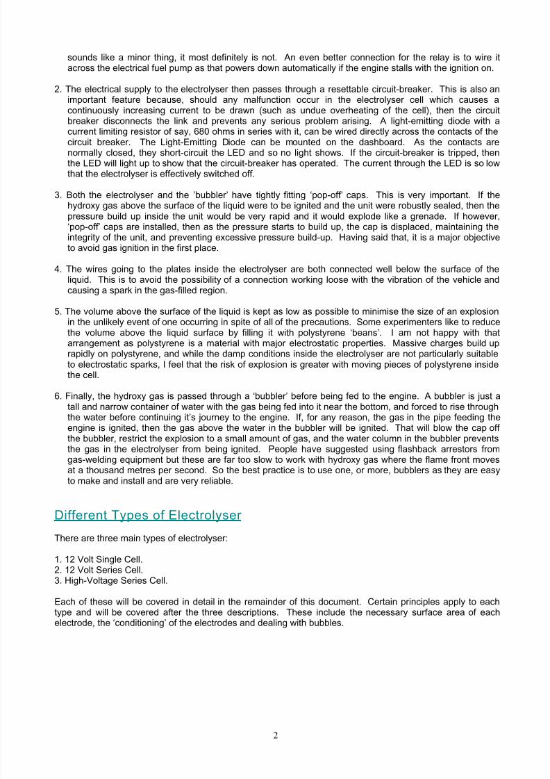
connected unit and the current will skip past the middle plates and just run from the first plate to the last platearound the sides of the other plates. So, the plates need to be a fairly tight push-fit in grooves cut in thesides and base of the housing. The electrolyte level must always be below the top of the plates as shownhere:
An electrolyser with a hundred cells, built in this style will have 101 metal plates and 100 separate bodies ofelectrolyte. In spite of these large numbers, the size of the overall unit does not have to be excessive. The
spacing between the plates is set to, say, 3 mm (1/8 inch) and the plate thickness might be 16 gauge (1/16inch), so the width of a 100-cell electrolyser is about 20 inches. In actual practice, the gaps at the end of theelectrolyser will also contain electrolyte although that electrolyte takes no part in the electrolysis process.
The size of the plates may be determined by the space available in the engine compartment. If there is alarge amount of spare space, then the plate size may be selected by allowing from two to four square inchesof area on both sides of each plate, per amp of current. Each side of every plate is in a different electrolysiscell so a 6-inch by 6-inch plate will have 36 square inches on each face and so would carry between 36 / 4 =9 to 18 amps of current. The choice of current is made by the builder of the electrolyser and it will beinfluenced by the size and cost of the inverter chosen to drive the electrolyser and the allowable current drawfrom the battery. This is for straight DC electrolysis where the battery is connected directly across theelectrolyser. Using Bob’s triple-oscillator electronics pulser card, the electrolyte level has to be kept down toabout three inches from the top of the six inch plate because the gas production rate is so high that there
has to be substantial freeboard to stop the electrolyte being splashed all over the place.
Bob usually uses a 6” x 6” plate size. It is essential that every item which contains hydroxy gas is locatedoutside the passenger compartment of any vehicle. Under no circumstances should the electrolyser orbubbler be located in the passenger area of the vehicle, even if pop-off caps are provided and a secondprotective outer housing is provided, as the explosive force is so great that permanent hearing damagewould be a serious possibility.
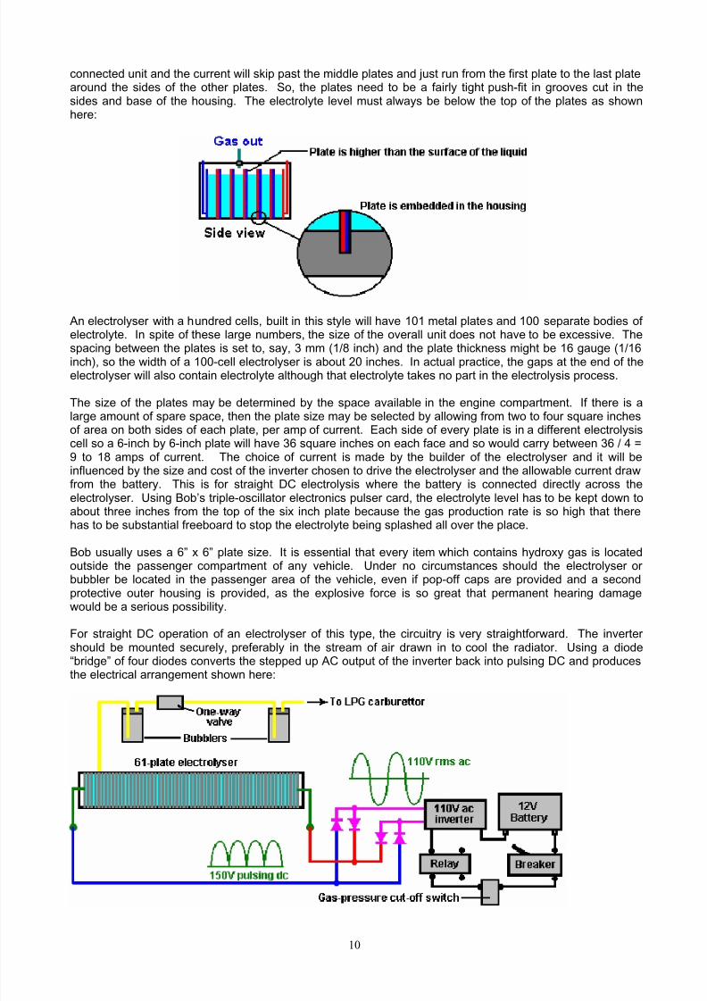
For straight DC operation of an electrolyser of this type, the circuitry is very straightforward. The invertershould be mounted securely, preferably in the stream of air drawn in to cool the radiator. Using a diode“bridge” of four diodes converts the stepped up AC output of the inverter back into pulsing DC and producesthe electrical arrangement shown here:

8/10/2019 Kelly and Boyce
http://slidepdf.com/reader/full/kelly-and-boyce 11/43
11
The one-way valve shown between the two bubblers, is to prevent the water in the bubbler mounted besidethe electrolyser, being driven into the electrolyser in the event of an explosion in the bubbler mounted besidethe engine.
Bob Boy ce’s Pulsed Electrolys er System
The following section of this document describes Bob Boyce’s highly efficient pulsed electrolysis system.This has been very generously shared freely by Bob so that anyone who wishes may construct one for theirown use without the payment of a licence fee or royalties. Just before presenting the details, it should bestressed that in order to get Bob’s performance of 600% to 1,000% of the Faraday (supposed) maximum gasoutput, each step needs to be carried out carefully exactly as described. Much of the following text is quotedfrom Bob’s forum posts and so should be considered as his copyright, not to be reproduced without hispermission.
Your Responsibi lity: If you decide to construct an electrolyser of this, or any other design, you do so wholly on your ownresponsibility, and nobody is in any way liable for any loss or damage, whether direct or indirect, resultingfrom your actions. In other words, you are wholly responsible for what you choose to do. I say again, thisdocument must not be construed as an encouragement for you to construct this or any other electrolyser.
Bob’s electrolyser splits water into a mixture of gases, mainly hydrogen and oxygen. That gas mixture,which will be referred to as “hydroxy” is highly explosive and must be treated with respect and caution. Afairly small volume of hydroxy gas exploded in air is quite liable to cause permanent hearing loss orimpairment due to the shock waves caused by the explosion. If hydroxy gas is ignited inside a sealedcontainer, then the resulting explosion is liable to shatter the container and propel shrapnel-like fragments inall directions. These fragments can cause serious injury and every precaution must be taken to ensure thatan explosion of that nature never happens. Bob uses two bubblers and a one-way valve to protect againstthis occurrence, and details of these are given in this document.
To make the water inside the electrolyser carry the necessary current, potassium hydroxide (KOH) is addedto distilled water. This is the best electrolyte for an electrolyser of this type. Potassium hydroxide is alsoknown as “caustic potash” and it is highly caustic. Consequently, it needs to be handled carefully and keptaway from contact with skin, and even more importantly, eyes. If any splashes come in contact with you, it isvery important indeed that the affected area be immediately rinsed off with large amounts of running waterand if necessary, the use of vinegar which is acidic.
This electrolyser design uses a torroidal transformer to interface the electronics to the electrolyser cells. It isvital that this transformer be used very carefully. Under no circumstances may this transformer be poweredup by the electronics when connected to anything other than the filled electrolyser cells as they act as asafety buffer. When driven by Bob’s electronics, this transformer draws additional energy from theenvironment. While this is very useful for electrolysis, there are sometimes unpredictable energy surgeswhich can generate as much as 10,000 amps of current. If one of these should occur when the transformeris not connected to the electrolyser which is able to soak up this excess, the resulting electrical conditionscan be very serious. If you are lucky, it will just burn out expensive components. If you are not lucky, it cancause a lightning strike which is liable to hit you. For that reason, it is absolutely essential that the toroidtransformer is never powered up with the secondary winding connected to anything other than the filledelectrolyser.
Patenting:It should be clearly understood that Bob Boyce, has released this information into the public domain and ithas been displayed publicly since early in 2006. It is not possible for any part of this information to be madepart of any patent application anywhere in the world. This prior public disclosure of the information preventsit being patented. It is Bob’s intention that this information be freely available to people world-wide.
The Objective: This is a “Hydroxy-On-Demand” (“HOD”) system. It is very difficult indeed to generate hydroxy gas fastenough to power an internal combustion engined vehicle under all road conditions. Moving from standstill to
8/10/2019 Kelly and Boyce
http://slidepdf.com/reader/full/kelly-and-boyce 12/43
12
rapid acceleration causes such a massive sudden requirement for additional volumes of hydroxy gas, that itis difficult to provide that volume instantly.
A better solution is to use an electric engine for the vehicle. This can be an electric vehicle which wasdesigned from scratch as such, or it can be a standard vehicle which has been adapted for electric engineuse. These electric vehicles are usually limited in how far they can travel, but a good solution to this is touse an electrical generator to charge the batteries, both when the vehicle is in use and when it is parked.
This electrolyser can be used to run such a generator on water. With this arrangement, there are no CO2emissions and the vehicle is very environmentally friendly. The batteries provide the necessary suddenacceleration demands and the generator recharges the batteries during normal driving.
Overview: Bob’s pulsed system has the following components:
1. An electrical connection to the vehicle’s electrical system (with safety features built in).
2. An “inverter” which raises the electrolyser voltage to 160 volts.
3. Bob’s specially designed circuit board which generates a complicated water-splitting waveform.
4. Bob’s specially designed toroidal transformer which links Bob’s circuit board to the electrolyser.
5. Bob’s specially prepared 101-plate series-connected electrolyser.
6. A dual-protection system for linking the electrolyser safely to the internal combustion engine.
None of these items is particularly difficult to achieve, but each needs to be done carefully and exactly asdescribed, paying particular attention to the detailed instructions.
Buildi ng the Case: The case needs to have very accurate slots cut in it. If you do not have a milling machine, then you shouldconsider getting a fabrication shop to mill the slots for you. The case has two ends, two sides, one base andone lid. Of these, the two sides and the base need 101 accurate grooves cut in them. The grooves arethere to hold the electrode plates securely in position, and yet give just enough slack to allow the electrolytelevels inside the cell, equalise if they should ever get out of step with each other. An extra three thousandthsof an inch in the slot width is sufficient to do this and still prevent any significant electrical flow around theplates. If you do not have the equipment to do this, then there is an enthusiast who is willing to do thecutting for people in the USA, and at reasonable price. To contact him for pricing and delivery details, sendan e-mail to [email protected].

8/10/2019 Kelly and Boyce
http://slidepdf.com/reader/full/kelly-and-boyce 13/43
13
The base and two sides of the cell have grooves cut in them. As the plates have to be slid in from the top,
the grooves in the side need to run the whole of the height of the side panel. As there has to be a securewatertight joint between the base and the sides, the slots cut in the base must not run the whole of the wayacross the base:
If it is difficult to cut grooves part way across with accurate ends, an alternative method for creating theshape is to attach a thinner piece of grooved acrylic to a plain base piece:

8/10/2019 Kelly and Boyce
http://slidepdf.com/reader/full/kelly-and-boyce 14/43
14
As it is difficult to cut a large number of very accurate grooves in acrylic, Bob uses the additional stripmethod for both the sides and the base, and uses the material used in plastic food-chopping boards for thestrips. This material “UHMW-PE” (Ultra High-Weight Polyethylene) or “HDPE” (High-Density Polyethylene)cuts reliably and is not brittle. Bob then uses the strips inside a one-inch thick acrylic case as it glues well.
The grooves which are cut for the plates should be three thousandths of an inch wider than the thickness ofthe plates. A good plate thickness is 16 gauge sheet which is one sixteenth of an inch thick or 0.0625 inch
(1.5875 mm), so the recommended groove width for that is 0.0655 inches which is not a convenient fractionbeing about four and one fifth sixty-fourths of an inch.
The supplier of the acrylic sheet needed for making the case, will be able to supply “glue” specificallydesigned for joining acrylic sheets together. This glue actually welds the plates together so that the sheetsbecome one continuous piece of acrylic along the joint. Start by mating the sides and the base. Insert twoor three plates into the slots to be quite sure that the alignment is spot-on during the joining process. Linethe ends up during jointing to be sure that the sides are completely square when being joined to the base.
Concerns have been expressed about the strength of the acrylic casing under severe road conditions. So ithas been suggested that the acrylic components be constructed from sheet which is 3/4” to 1” thick (18 mmto 25 mm) and the corners reinforced with angle iron secured with bolts tapped into the acrylic as shownhere:
Getting and Preparing the Plates: A set of 101 plates is needed for the electrolyser. The material used when making the plates is veryimportant. It should be 16-gauge 316L-grade stainless steel as it contains a blend of nickel andmolybdenum in the correct proportions to make it a very good catalyst for the pulsing technique. You can tryyour local steel stockists to see if they can supply it and what their charges would be. One satisfactorystainless steel supplier which Bob has used is Intertrade Steel Corp., 5115 Mt. Vernon Rd SE, CedarRapids, IA 52406. Do not buy from eBay as you have no real comeback if the plates supplied are disheddue to having been flame cut. Possible internet suppliers include
AK Steel. Middletown, OH 513-425-5000 www.aksteel.com
Allegheny Ludlum, Pittsburgh, PA 412-394-2800 www.alleghenyludlum.com Allvac, Monroe, NC 800-841-5491 www.allvac.com Carpenter Technology Corporation, Reading, PA 610-208-2000 www.cartech.com Talley Metals Technology Inc., Hartsville, SC 843-335-7540

8/10/2019 Kelly and Boyce
http://slidepdf.com/reader/full/kelly-and-boyce 15/43
15
Crucible Specialty Metals, Syracuse, NY 315-487-4111 www.crumetals.com Electralloy, Oil City, PA 814-678-4100 www.electralloy.com North American Stainless, Ghent, KY 502-347-6000 www.northamericanstainless.com Outokumpu Stainless, Schaumburg, IL 800-833-8703 www.outokumpu.com Special Metals Corporation, New Hartford, NY 315-798-2900 www.specialmetals.com Timken Latrobe Steel, Latrobe, PA 724-537-7711 www.timken.com Universal Stainless & Alloy Products, Bridgeville, PA 412-257-7600 www.univstainless.com
Valbruna Slater Stainless, Ft. Wayne, IN 260-4334-2800 www.valbruna.com Mexico: ThyssenKrupp Mexinox SA de CV, San Luis Potosi, Mexico 5248-265139 www.mexinox.com UK: www.metalsdirectuk.com
It is very important indeed that when asking for a quote that you make sure that the supplier is aware of theaccuracy you require. The plates need to be flat to a tolerance of +/- 0.001" after cutting and this is the mostimportant factor. That level of accuracy excludes any kind of flame cutting as it produces inevitable heatdistortion. With shearing, expect +/- 0.015" on the cuts and +/- 0.001" on flatness. Laser cutting producesmuch higher accuracy and you can expect as good as +/- 0.005" on cuts and there is no spec needed forflatness since laser cutting does not distort the edges like shearing does.
The plates are square: 6-inches by 6-inches, but that does not represent 36 square inches of active surfacearea as some plate area is inside the grooves and some of each plate is above the surface of the electrolyte.
Another point to remember is that 101 steel plates this size weigh a considerable amount and the completedelectrolyser with electrolyte in it will weigh even more. It is essential therefore to have a case which isstrongly built from strong materials, and if a mounting bracket is to be used, then that bracket needs to bevery robust and well secured in place.
The preparation of the plates is one of the most important steps in producing an electrolyser which workswell. This is a long task, but it is vital that it is not skimped or hurried in any way. Surprisingly, brand newshiny stainless steel is not particularly suitable for use in an electrolyser and it needs to receive carefultreatment and preparation before it will produce the expected level of gas output.
The first step is to treat both surfaces of every plate to encourage gas bubbles to break away from thesurface of the plate. This could be done by grit blasting, but if that method is chosen, great care must betaken that the grit used does not contaminate the plates. Stainless steel plates are not cheap and if you get
grit blasting wrong, then the plates will be useless as far as electrolysis is concerned. A safe method whichBob much prefers is to score the plate surface with coarse sandpaper. This is done in two differentdirections to produce a cross-hatch pattern. This produces microscopic sharp peaks and valleys on thesurface of the plate and those sharp points and ridges are ideal for helping bubbles to form and break free ofthe plate.
Bob uses a 6-inch x 48-inch belt sander which is great for preparing the plates and he uses it all the timenow with 60 or 80 grit. Always wear rubber gloves when handling the plates to avoid getting finger marks on

8/10/2019 Kelly and Boyce
http://slidepdf.com/reader/full/kelly-and-boyce 16/43
16
the plates. Wearing these gloves is very important as the plates must be kept as clean and as grease-freeas possible, ready for the next stages of their preparation.
Any particles created by the sanding process should now be washed off the plates. This can be done withclean tap water (not city water though, due to all the chlorine and other chemicals added), but only usedistilled water for the final rinse.
A point which is often missed by people constructing electrolysers is the fact that electrolysis is not just anelectrical process, but it is also a magnetic process. It is important for maximum operating efficiency that theplates are aligned magnetically. This will not be the case when the plates arrive from the supplier as eachplate will have random magnetic characteristics. The easiest way to deal with this situation is to give theplates a mild magnetic orientation. This can be done quite simply by wrapping a few turns of wire around thestack of plates and passing some brief pulses of DC current through the wire.
Obviously, the plates need to be kept in the same direction when being slotted into the case. The next stepin the preparation process is to make up a weak solution of potassium hydroxide. This is done by addingsmall amounts of the potassium hydroxide to water held in a container. The container must not be glass asthat is not a suitable material in which to mix the electrolyte.
Potassium hydroxide, also called KOH or “Caustic Potash”, can be bought in small quantities from soapmaking supply outlets. One suitable outlet is Summer Bee Meadow at www.summerbeemeadow.com intheir “Soapmaking Supplies” section. Another provider who supplies small quantities at reasonable cost ishttps://www.saltcitysoapworks.com/newshop/product_info.php?cPath=25&products_id=106&osCsid=07d7dba060277e6c8a157be165490541 While Potassium hydroxide is the very best electrolyte, it needs to betreated with care:
Always store it in a sturdy air-tight container which is clearly labelled "DANGER! - Potassium Hydroxide".Keep the container in a safe place, where it can’t be reached by children, pets or people who won't take anynotice of the label. If your supply of KOH is delivered in a strong plastic bag, then once you open the bag,
you should transfer all its contents to sturdy, air-tight, plastic storage containers, which you can open andclose without risking spilling the contents. Hardware stores sell large plastic buckets with air tight lids thatcan be used for this purpose.
When working with dry KOH flakes or granules, wear safety goggles, rubber gloves, a long sleeved shirt,socks and long trousers. Also, don’t wear your favourite clothes when handling KOH solution as it is not thebest thing to get on clothes. It is also no harm to wear a face mask which covers your mouth and nose. Ifyou are mixing solid KOH with water, always add the KOH to the water, and not the other way round, anduse a plastic container for the mixing, preferably one which has double the capacity of the finished mixture.The mixing should be done in a well-ventilated area which is not draughty as air currents can blow the dryKOH around.
When mixing the electrolyte, never use warm water. The water should be cool because the chemical
reaction between the water and the KOH generates a good deal of heat. If possible, place the mixingcontainer in a larger container filled with cold water, as that will help to keep the temperature down, and ifyour mixture should “boil over” it will contain the spillage. Add only a small amount of KOH at a time, stirringcontinuously, and if you stop stirring for any reason, put the lids back on all containers.

8/10/2019 Kelly and Boyce
http://slidepdf.com/reader/full/kelly-and-boyce 17/43
17
If, in spite of all precautions, you get some KOH solution on your skin, wash it off with plenty of running coldwater and apply some vinegar to the skin. Vinegar is acidic, and will help balance out the alkalinity of theKOH. You can use lemon juice if you don't have vinegar to hand - but it is always recommended to keep abottle of vinegar handy.
Plate Cleansing:
Prepare a 5% to 10% (by weight) KOH solution and let it cool down. As mentioned before, never handle theplates with your bare hands, but always use clean rubber gloves. Put the sanded and rinsed plates into theslots in the electrolyser case, keeping them all the same way round so that they remain magneticallymatched. Fill the electrolyser with the KOH solution until the plates are just covered.
A voltage is now applied across the whole set of plates by attaching the leads to the outermost two plates.This voltage should be at least 2 volts per cell, but it should not exceed 2.5 volts per cell. Maintain thisvoltage across the set of plates for several hours at a time. The current is likely to be 4 amps or more. Asthis process continues, the boiling action will loosen particles from the pores and surfaces of the metal. Thisprocess produces hydroxy gas, so it is very important that the gas is not allowed to collect anywhere indoors(such as on ceilings).
After several hours, disconnect the electrical supply and pour the electrolyte solution into a container. Rinseout the cells thoroughly with distilled water. Filter the dilute KOH solution through paper towels or coffeefilters to remove the particles. Pour the dilute solution back into the electrolyser and repeat this cleaningprocess. You may have to repeat the electrolysis and rinsing process many times before the plates stopputting out particles into the solution. If you wish, you can use a new KOH solution each time you cleanse,but please realise that you can go through a lot of solution just in this cleaning stage if you choose to do itthat way. When cleansing is finished (typically 3 days of cleansing), do a final rinse with clean distilledwater.
Plate Conditioning: Using the same concentration of solution as in cleansing, fill the electrolyser with dilute solution up to 1/2"below the tops of the plates. Do not overfill the cells. Apply about 2 volts per cell and allow the unit to run.
Remember that very good ventilation is essential during this process. The cells may overflow, but this is okfor now. As water is consumed, the levels will drop. Once the cells stabilise with the liquid level at the platetops or just below, monitor the current draw. If the current draw is fairly stable, continue with thisconditioning phase continuously for two to three days, adding just enough distilled water to replace what isconsumed. If the solution changes colour or develops a layer of crud on the surface of the electrolyte, thenthe cell stack needs more cleansing stages. Do not allow the cells to overfill and overflow at this point. Aftertwo to three days of run time, pour out the dilute KOH solution and rinse out the electrolyser thoroughly withdistilled water.
Cell Operation: Mix up a nearly full-strength solution of potassium hydroxide. The filling of the electrolyser depends onwhether straight DC electrolysis is to be used, or resonant electrolysis is to be used.
For straight DC electrolysis, fill the electrolyser to about one inch below the tops of the plates. The DCvoltage applied to the electrolyser will be about 2 volts per cell or a little less, so this 100-cell electrolyser willhave 180 to 200 volts applied to it. This voltage will be generated with an inverter.
For resonant operation, fill the electrolyser to only half the plate height because the hydroxy gas productionis so rapid that room has to be left for the gas leaving the plates. With resonant operation, about 1.5 voltsper cell is used.
Troubleshooting: 1. Abnormally low current is caused by improper plate preparation or severe contamination. Take the plates
out of the electrolyser and start over again from plate preparation.
2. Abnormally high current is caused by high leakages between cells. This will require re-building or re-sealing of the electrolyser case.

8/10/2019 Kelly and Boyce
http://slidepdf.com/reader/full/kelly-and-boyce 18/43
18
3. If current starts higher then drops off, this means that the plates are contaminated. Take the plates out ofthe electrolyser and start over again from plate preparation.
Building the Electronics:
Resonant operation of the electrolyser requires the use of a DC pulsing system. Bob has designed anadvanced system for this, consisting of a sophisticated electronics board and a finely-tuned toroidaltransformer which interfaces and matches the electronics to the electrolyser.
The electronics board produces three separate frequencies which are combined together to give a rich andcomplex output waveform further modified by the toroidal transformer:
In Bob’s electrolyser build, those frequencies were about 42.8 KHz, 21.4 KHz and 10.7 KHz but please don’tget the wrong impression here, there is no single exact frequency or set of frequencies which should beused. The size and shape of your cell, the electrodes spacings, electrolyte density, electrolyte temperatureand operational pressure are all factors which affect the tuning of the electronics. With Bob’s large marine-duty cells with square twelve-inch plates, he found the base resonance point using his original, modified
inverter, to be at least 100 Hz lower than that of the prototypes with smaller plate sizes.
When he tried separate flooded cells connected in series, he was not able to get anything more than amarginal rise in performance over a broader range. He felt that this was due to each cell in the set having aslightly different resonant point which did not match very well with the other cells. Bob had to go to theseries plate design with accurate spacing and tight tolerance on slots and plates in order to get the resonantresponses to line up on all cells. Also, he found that some choices of electrolyte would not produceresonance at any frequency, though he is not sure why. Some worked well while others worked marginally,so Bob stuck with what worked the best for him - sodium hydroxide (NaOH) and potassium hydroxide (KOH).
It needs to be stressed here, that every electrolyser build is slightly different from all others, even thoughthey may have been meant to be exactly the same. There will be small differences between the plates inone electrolyser and the plates in other electrolysers. The electrolyte concentration will be slightly different,the plate preparation will be slightly different and the overall magnetic characteristics will be unique to eachactual build. For that reason, the tuning of the completed electronics board and the construction of the bestpossible transformer to match the electronics to the electrolyser, is always different for each electrolyserbuilt.

8/10/2019 Kelly and Boyce
http://slidepdf.com/reader/full/kelly-and-boyce 19/43
19
The first step is to build the electronics control board. The methods for doing this are shown clearly in Bob’sdocument entitled “Boyce Electrolyser Project.pdf” which is in the “Files” section of the WorkingWatercarYahoo forum. Bob has designed a printed circuit board to simplify the construction of the electronic drivecircuitry. To see Bob’s design and to order one of these boards, you need to download and install the free“ExpressPCB” software which is located at http://www.expresspcb.com/ExpressPCBHtm/Download.htm andwhich can display his design files. The download is just over nine megabytes in size and contains two
programs: “ExpressPCB” and “ExpressSCH”. Only the ExpressPCB program needs to be installed for youto be able to place an order for a board.
The design files needed for you to be able to order the printed circuit board, are located in the “Bob BoyceProject” folder in the “Files” section of the WorkingWatercar forum. If you are not already a member of thisYahoo Group, then you need to join at http://tech.groups.yahoo.com/group/WorkingWatercar/ which is agood idea anyway as the forum members are always willing to give helpful advice. The “Bob Boyce Project”folder contains the “Boyce Electrolyser Project.pdf” document describing the construction of the electronics.
You need to use the ExpressPCB program to access the “PWM3F.pcb” file which is in the “Bob BoyceProject” folder, as this small 50 Kb file contains the design and construction information needed by themanufacturer to construct the board for you. Download the PWM3F.pcb file on to your computer anddouble-click on it to open it with your newly installed ExpressPCB program. When the file has loaded, click
on the “Layout” option at the top of the screen and then click on Click the "Compute Board Cost", enter yourlocation, select the Two-layer Board option, then pick “MiniBoard”. Alternatively, you can get the board fromThe Hydrogen Garage for just US $20 at:http://stores.homestead.com/hydrogengarage/Categories.bok?category=ELECTRICAL+%2F+CIRCUITSalong with other useful items like an ammeter for checking the current flow through the electrolyser.
When your new printed circuit board is delivered, you will need the components to be mounted on it. Terryhas set up a pre-filled order form for Digikey which you can use without having to key all the informationyourself. Just click on this link: http://sales.digikey.com/scripts/ru.dll?action=pb_view&pb_glue=1014385 toorder the parts which will cost about US $60 for US mainland shipping.
The completed board looks like this:

8/10/2019 Kelly and Boyce
http://slidepdf.com/reader/full/kelly-and-boyce 20/43
20
It is not too difficult to assemble this board as the printed circuit board can be purchased ready-made and acomplete set of components can be ordered using the ordering system set up in the WorkingWatercar forum.
You should notice here, that the whole of the aluminium case is being used as a “heat-sink” to dissipate theheat generated in the FET driver transistors. These transistors are all bolted to the case and each has it’sown rectangle of mica “washer” between the transistor and the case. These pieces of mica pass heat veryreadily to the case, while at the same time, isolating the transistors electrically so that they will not interferewith each other. Notice too, the plastic support columns at each corner of the printed circuit board. Theseare used to mount the printed circuit board securely, while holding it away from the metal case and sopreventing any possibility of the connections on the underside of the board being short-circuited by the caseitself.
In some of the builds of the electronics board, it has been found that it is sometimes difficult to get thehighest frequency oscillator operating correctly at around 42.8 KHz due to some NE556 chips being out ofspecification. Even though they should be the same, chips from different manufacturers, and even the samebranded chip from different suppliers, can have slightly different actual specifications. On both the PWM3Eand PWM3F boards, C4 has now been changed from 0.1 microfarad back to 0.047 microfarad toaccommodate the corrected specs of the newer Texas Instruments NE556N chip (the one marked withMALAYSIA on top). The earlier versions of the NE556N chip had required a change to 0.1 microfarad tocorrect for specifications that were sub-standard. Depending on which chip you actually use in the “U1 - U3”board positions, you may have to adjust the value of C1, C3, and C4 to compensate for variations from theoriginal 556 chip specification, or adjust some of the other timing component tolerances. The TAIWAN andother marked Texas Instruments chips will still work ok in the “U2” and “U3” locations, but there has been abig issue sourcing chips that will reach 43 kHz in the “U1” location. The MALAYSIA chips tested so far havebeen satisfactory.
Setting up the completed board:
Jumper J1 : If this is short-circuited it disables all three Pulse-Width Modulators, for oscillator outputs only.Jumper J2 : If this is short-circuited it connects the MOSFET Gate Supply TB3 to +DC for a single supply.Jumper J3 : If this is short-circuited it connects the MOSFET Source to -DC for a common ground.Jumper J4 : If this is short-circuited it enables the input of the Auxiliary TTL Inputs 1, 2 and 3. This is a
convenient test point for measuring the outputs of each of the three signal generator stages.To enable the auxiliary inputs, the on-board generators must be disabled with SW1 switches 1,2 and 3 as shown here:
Switch SW1 : switching 1 on disables the Pulse-Width Modulation of oscillator 1switching 2 on disables the Pulse-Width Modulation of oscillator 2

8/10/2019 Kelly and Boyce
http://slidepdf.com/reader/full/kelly-and-boyce 21/43
21
switching 3 on disables the Pulse-Width Modulation of oscillator 3switching 4 on disables the Pulse-Width Modulation of all three oscillators

8/10/2019 Kelly and Boyce
http://slidepdf.com/reader/full/kelly-and-boyce 22/43
22
Terminal Block TB1 : is the DC Power Input & MOSFET Source Ground
Terminal Block TB2 : is the MOSFET Drain/PWM Outputs & MOSFET Gate Supply Input
In more detail:
J1 is for the connection of an optional external control or safety shutdown device, such as a pressure ortemperature limit switch. J1 is shorted to shut down waveform generation. For normal operation, J1 is leftopen.
J2 and J3 are for optional voltage modification support. For normal operation, both J2 and J3 are shortedwith 2 position jumper shorting blocks.
J4 is for the connection of optional auxiliary inputs. For normal operation, nothing is connected to J4. J4can also be used to connect an oscilloscope to view the P ulse- Width Modulator generator waveforms ofchannels 1, 2, and 3.

8/10/2019 Kelly and Boyce
http://slidepdf.com/reader/full/kelly-and-boyce 23/43
23
SW1 is for disabling PWM generator channels 1, 2, and 3 via switches 1, 2, and 3. Switch 4 is a masterdisable that turns off all 3 channels. For normal operation, all 4 switches are switched OFF.
Terminal Block TB1 has 4 connections as follows;
1. DC Input + is connected to the 13.8 V DC power supply positive connection via a 2-amp fuse or circuitbreaker.
2. DC Input - is connected to the 13.8 V DC power supply negative connection. If a shorting plug is installedat J3, this wire is optional.
3. and 4. Ground is connected to the 13.8 V DC power supply negative connection via heavy gauge wire.There are two wire connection terminals available so that two equal length wires may be used to reducewire resistance losses.
Terminal B lockTB2 has 4 connections which are connected as follows:
Gate + is not normally connected when a shorting plug is installed at jumper J2.Output 1 is connected to the “cold” side of primary 1 of the toroidal transformer.
Output 2 is connected to the “cold” side of primary 2 of the toroidal transformer.Output 3 is connected to the “cold” side of primary 3 of the toroidal transformer.
The “hot” sides of primaries 1, 2, and 3 are brought together, and connected to the 13.8 V DC power supplypositive connection via heavy-gauge wire and a 60-amp fuse or DC circuit-breaker.
Note: These fuses are for short circuit protection, and are not an indication of system power consumption.
Testing the completed board: Do NOT connect the PWM3F outputs to a powered transformer until after the unit tests show it to be fullyfunctional. You may pull the 60-amp fuse out, or trip the DC circuit-breaker, while testing and tuning.
Power up the PWM3F board and check the indicator LEDs for proper operation:
LED 1 - the Channel 1 output - should be lit in normal operation, off if disabled.LED 2 - the Channel 2 output - should be lit in normal operation, off if disabled.LED 3 - the Channel 3 output - should be lit in normal operation, off if disabled.
LED 4 - the PWM channel 1 disable - should be off in normal operation, on if disabled.LED 5 - the PWM channel 2 disable - should be off in normal operation, on if disabled.LED 6 - the PWM channel 3 disable - should be off in normal operation, on if disabled.
LED 7 - the 12 volt supply - should be lit in normal operation, off when powered down.LED 8 - the 8 volt supply - should be lit when the power is connected and off when powered down.
If all indicators check out, then start the tuning procedure. If everything checks out ok except the outputindicators, then try tuning first then test again. Failures may indicate component or soldering problems.
Tuning the board: Adjust all 3 of the "DC" marked (Duty Cycle) potentiometers (R25, R27, R29) fully clockwise, for minimumpulse width.
Connect a frequency counter or oscilloscope to Jumper J4 pin 1 (Aux Input 3) and adjust the channel 3 "Hz"marked potentiometer (R28) for a reading of 10.7 KHz.
Connect a frequency counter or oscilloscope to Jumper J4 pin 2 (Aux Input 2) and adjust the channel 2 "Hz"marked potentiometer (R26) for a reading of 21.4 KHz.

8/10/2019 Kelly and Boyce
http://slidepdf.com/reader/full/kelly-and-boyce 24/43
24
Connect a frequency counter or oscilloscope to Jumper J4 pin 3 (Aux Input 1) and adjust the channel 1 "Hz"marked potentiometer (R24) for a reading of 42.8 KHz.
Note: If channel 1 shuts down while tuning towards 42.8 KHz, replace U1 with a different brand of NE556type timer chip. Many of these chips, like those marked as made in Taiwan, do not fully meet the NE555spec and will shut down with the output turned on solid. If this occurs while loaded, the output FET for thatchannel may be quickly destroyed. The Texas Instruments 556 chips marked as made in Malaysia have
typically been tested to work ok at up to 45 KHz.Once the board has been tuned as described above, verify output at the Terminal Block TB2 Outputs with anoscilloscope. Without a transformer connected, the indicator LEDs only lightly load the FETs, but enough toverify operation during testing. If all checks out ok up to this point, you should be ready to connect thetransformer primaries and apply power.
Note: If you experience heating issues with any of the Metal Oxide Varistors M1, M2, and M3, they may besafely removed and left out, or replaced with slightly higher voltage MOVs. There have been some MetalOxide Varistors that work properly, and some that do not. It seems to be a batch related issue.
Winding the Transformer:
The transformer in Bob’s system is a very important component. It is an inductor, a transformer, and asource of energy-form conversion, all rolled into one. The transformer has been successfully duplicated andused by others, driven with Bob’s triple-oscillator board, to achieve a resonant drive to the cells which resultsin a performance which is well beyond the maximum stated by Faraday.
The reason there are no step-by-step instructions for constructing the transformer is because it must bewound to match the load/impedance of the cells it will be driving. There is no “one-transformer-fits-all”solution for this. Bob uses a powdered iron core of 6.5" diameter for units up to 100 cells. The larger thediameter, the greater the power. Ferrite is fine for lower frequencies, but for this application, a powdered irontoroid core is essential. The MicroMetals core, part number “T650-52” is a suitable core and is availablefrom http://www.micrometals.com/pcparts/torcore7.html and can be purchased in small quantities via their"samples requests", which can be submitted at http://www.micrometals.com/samples_index.html
The primary of the transformer is 3-phase, while the secondary is single-phase. As most current flows alongthe outside of wires rather than through the middle of the wire, the choice and size of the wire chosen towind the transformer is most important. Bob uses solid teflon-covered silver-plated copper wire. It is veryimportant that this wire is solid core and not stranded as stranded wire does not work here (due to thegeneration of inter-strand, phase-differential induced eddy currents). Before any winding is done, the toroidis given a layer of tape. And the materials to be used are collected together, namely, the tape, the wire, thebeeswax and the heat gun:

8/10/2019 Kelly and Boyce
http://slidepdf.com/reader/full/kelly-and-boyce 25/43
25
Of paramount importance with the toroid is that unlike traditional transformer design, the secondary is woundfirst, and the windings must be evenly spaced where they fan out from the center of the core. This meanseven though they are tightly packed right up against one another at the center hole, they must not be woundso that they bunch up and gap open around the periphery. Mistakes here will cause field errors that willlower the overall efficiency.
As you can see here, Bob uses short lengths of plastic strimmer cable as spacers for the outside of thetoroid, though the picture above has been taken to show what a partially prepared secondary winding lookslike when its windings are being moved into very accurate positions.
You will notice that Bob has wrapped the toroid in tape before starting the secondary winding:

8/10/2019 Kelly and Boyce
http://slidepdf.com/reader/full/kelly-and-boyce 26/43
26
Bob also uses a jar to assist in applying beeswax to the accurately positioned turns of the toroidaltransformer:
When the windings are completed, correctly spaced and encased in beeswax, each layer is finished off witha layer of tape.
So, to recap, the toroid is wrapped in tape, the primary wound extending the entire way around the toroid,
the windings carefully spaced out so that the gaps around the outer edge of the toroid are exactly equal, thewinding encased in beeswax, and then the beeswax covered with a layer of tape:

8/10/2019 Kelly and Boyce
http://slidepdf.com/reader/full/kelly-and-boyce 27/43
27
For the great majority of systems, the secondary winding is a tightly wound, single layer, full-fill wrap of 16gauge, single-core, silver-plated, teflon-insulated copper wire. There will be about 140 turns in this windingand that will be a length of about 90 feet of wire. Count the exact number of turns in your actual winding andmake a note of it. This secondary winding is held in place with melted beeswax, and when that hashardened, the winding is then wrapped tightly with a good quality plastic tape. This makes a good base forthe primary windings which will be wound on top of the tape layer.

8/10/2019 Kelly and Boyce
http://slidepdf.com/reader/full/kelly-and-boyce 28/43
28
Please note that every winding starts by passing over the toroid, proceeds in a counter-clockwise direction,and finishes by passing under the toroid. Every winding is created in this way and the quality ofworkmanship is very important indeed when making these windings. Each winding needs to be tight andpositioned exactly with turns touching each other in the centre of the toroid and positioned on the outer edgewith exactly equal spaces between each turn. Your construction work has to be better than that of acommercial supplier and needs to reach the quality demanded by the military, which would cost thousandsof dollars for each toroid if it were to be made up for you by professionals.
The three primaries need to be wound on top of the tape wrapping which covers the secondary winding.These three windings are spaced out equally around the toroid, that is, at 120 degree centres. The primarywindings are held in place with beeswax, and then tightly taped. The primaries may need more than a singlelayer, and they are wound with the same direction of winds as the secondary, and the same care for evenwinding spacing as the secondary needed. Tape the entire core well with tightly-stretched PVC electricaltape after winding, to ensure that the primary windings do not move and then add an outer layer of windingtape.
This is where the generic information ends. The exact details of the primary windings must be determinedfrom the operational characteristics of the cells. This means that you must build, cleanse and condition yourcells prior to making the operational measurements. From those measurements, calculations can be madeto determine what gauge and how many turns of solid-core, silver-plated, teflon-insulated, copper wire are to
be used for each of the three primary windings.The objective here is to have the complex waveform generated by the electronics produce voltages of about25% of the main power supply voltage at the electrolyser. In other words, if an inverter is being used and itsoutput rectified to produce about 155 volts of pulsing DC, then the toroid transformer secondary shouldgenerate about 40 volts.
The output from the electronics board is about 13.8 volts when driven by a vehicle’s electrical system, so tostep that up to about 40 volts requires a step up of 2.9, which means that the secondary winding needs tohave 2.9 times as many turns in it as the primary winding does. So divide the number of turns in yoursecondary winding by 2.9 to calculate the number of turns in each of the three primary windings. If you had140 turns in the secondary, then there would be 48 turns in each of the three primary windings.
The diameter of the wire used in the primaries will normally be greater than that of the secondary because itwill be driven by a much lower voltage and so will need a much higher current. Now that you have cleansedand conditioned the plates in your electrolyser, power up your inverter with your vehicle engine running at2000 rpm or so, and measure the DC current taken by the inverter. This is the level of current which theprimary windings have to carry, so the wire size can be selected from this measurement. Each primarywinding is pulsed, so it is not carrying current all of the time, also, the final primary current is the sum of thethree pulsing signals, so a reduction can be allowed for that. While the wire diameter for the primarywindings of each toroidal transformer need to be calculated separately, a common diameter turns out to be
AWG #20 (21 SWG). The wire length for the primaries will be greater per turn as the turns are now beingmade over the secondary winding. Forty-eight turns of #20 wire are likely to require at least thirty-five feetand that is for each of the three windings, assuming that all turns can be laid flat side-by-side. If it isnecessary to make each a two-layer winding, then the wire length will increase further.
If you would like a 360 degree template for marking the positions of the primary windings, then there is oneavailable at www.thegsresources.com
8/10/2019 Kelly and Boyce
http://slidepdf.com/reader/full/kelly-and-boyce 29/43
29
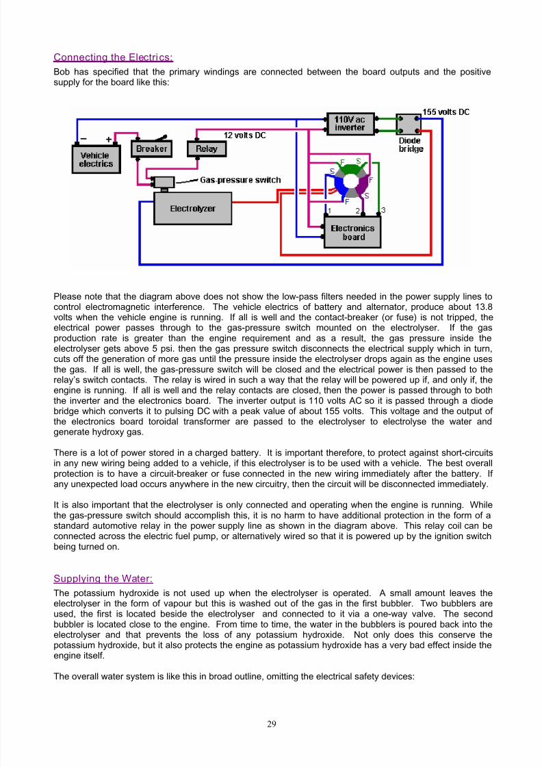
Connecting the Electri cs: Bob has specified that the primary windings are connected between the board outputs and the positivesupply for the board like this:
Please note that the diagram above does not show the low-pass filters needed in the power supply lines tocontrol electromagnetic interference. The vehicle electrics of battery and alternator, produce about 13.8volts when the vehicle engine is running. If all is well and the contact-breaker (or fuse) is not tripped, theelectrical power passes through to the gas-pressure switch mounted on the electrolyser. If the gasproduction rate is greater than the engine requirement and as a result, the gas pressure inside theelectrolyser gets above 5 psi. then the gas pressure switch disconnects the electrical supply which in turn,cuts off the generation of more gas until the pressure inside the electrolyser drops again as the engine usesthe gas. If all is well, the gas-pressure switch will be closed and the electrical power is then passed to therelay’s switch contacts. The relay is wired in such a way that the relay will be powered up if, and only if, theengine is running. If all is well and the relay contacts are closed, then the power is passed through to both
the inverter and the electronics board. The inverter output is 110 volts AC so it is passed through a diodebridge which converts it to pulsing DC with a peak value of about 155 volts. This voltage and the output ofthe electronics board toroidal transformer are passed to the electrolyser to electrolyse the water andgenerate hydroxy gas.
There is a lot of power stored in a charged battery. It is important therefore, to protect against short-circuitsin any new wiring being added to a vehicle, if this electrolyser is to be used with a vehicle. The best overallprotection is to have a circuit-breaker or fuse connected in the new wiring immediately after the battery. Ifany unexpected load occurs anywhere in the new circuitry, then the circuit will be disconnected immediately.
It is also important that the electrolyser is only connected and operating when the engine is running. Whilethe gas-pressure switch should accomplish this, it is no harm to have additional protection in the form of astandard automotive relay in the power supply line as shown in the diagram above. This relay coil can be
connected across the electric fuel pump, or alternatively wired so that it is powered up by the ignition switchbeing turned on.
Supplying the Water: The potassium hydroxide is not used up when the electrolyser is operated. A small amount leaves theelectrolyser in the form of vapour but this is washed out of the gas in the first bubbler. Two bubblers areused, the first is located beside the electrolyser and connected to it via a one-way valve. The secondbubbler is located close to the engine. From time to time, the water in the bubblers is poured back into theelectrolyser and that prevents the loss of any potassium hydroxide. Not only does this conserve thepotassium hydroxide, but it also protects the engine as potassium hydroxide has a very bad effect inside theengine itself.
The overall water system is like this in broad outline, omitting the electrical safety devices:
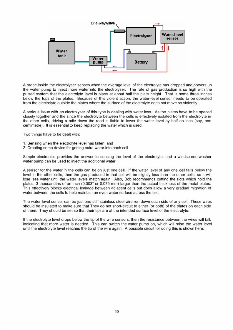
8/10/2019 Kelly and Boyce
http://slidepdf.com/reader/full/kelly-and-boyce 30/43
30
A probe inside the electrolyser senses when the average level of the electrolyte has dropped and powers upthe water pump to inject more water into the electrolyser. The rate of gas production is so high with thepulsed system that the electrolyte level is place at about half the plate height. That is some three inchesbelow the tops of the plates. Because of this violent action, the water-level sensor needs to be operatedfrom the electrolyte outside the plates where the surface of the electrolyte does not move so violently.
A serious issue with an electrolyser of this type is dealing with water loss. As the plates have to be spacedclosely together and the since the electrolyte between the cells is effectively isolated from the electrolyte inthe other cells, driving a mile down the road is liable to lower the water level by half an inch (say, onecentimetre). It is essential to keep replacing the water which is used.
Two things have to be dealt with:
1. Sensing when the electrolyte level has fallen, and2. Creating some device for getting extra water into each cell
Simple electronics provides the answer to sensing the level of the electrolyte, and a windscreen-washerwater pump can be used to inject the additional water.
A sensor for the water in the cells can be on just one cell. If the water level of any one cell falls below thelevel in the other cells, then the gas produced in that cell will be slightly less than the other cells, so it willlose less water until the water levels match again. Also, Bob recommends cutting the slots which hold theplates, 3 thousandths of an inch (0.003” or 0.075 mm) larger than the actual thickness of the metal plates.This effectively blocks electrical leakage between adjacent cells but does allow a very gradual migration ofwater between the cells to help maintain an even water surface across the cell.
The water-level sensor can be just one stiff stainless steel wire run down each side of any cell. These wiresshould be insulated to make sure that They do not short-circuit to either (or both) of the plates on each sideof them. They should be set so that their tips are at the intended surface level of the electrolyte.
If the electrolyte level drops below the tip of the wire sensors, then the resistance between the wires will fall,indicating that more water is needed. This can switch the water pump on, which will raise the water leveluntil the electrolyte level reaches the tip of the wire again. A possible circuit for doing this is shown here:

8/10/2019 Kelly and Boyce
http://slidepdf.com/reader/full/kelly-and-boyce 31/43
31
When the level of the electrolyte falls, the sensor wires come clear of the liquid and the voltage at point ‘A’rises. Provided that this situation remains for a second or two, capacitor C2 charges up and the voltage onthe base of transistor Tr1 rises, causing it to switch on. Transistors Tr1 and Tr2 are wired as a Schmitttrigger, so transistor Tr2 changes state rapidly, raising the voltage at its collector, and causing transistor Tr3to power the relay on. The relay contacts switch the water pump on, which raises the level of the electrolyteuntil it reaches the sensor wires again. This flips the circuit back into its standby state, powering down thewater pump. Resistor R1 feeds capacitor C1 to reduce the effects of variations of voltage reaching thesensor circuit. The components shown here are not critical and there must be at least twenty alternativedesigns for this circuit.
A possible physical layout for this circuit is shown here:
The build is based on using the standard 10-strip, 39-hole stripboard. For convenience in drawing, the holes
are represented as the points where the lines cross in the diagram shown here:
The horizontal lines represent the copper strips and the intersections with the vertical lines represents thematrix of holes. Many different layouts could be used for this circuit, so the following diagram is only asuggestion:

8/10/2019 Kelly and Boyce
http://slidepdf.com/reader/full/kelly-and-boyce 32/43
32
Components:
R1 100 ohms C1 1000 microfarad 35 volt or higherR2 1,000 ohms C2 330 microfarad 16 volt or higher
R3 10,000 ohmsR4 1,800 ohms D1 1N4001 or similar 100 volt or higher 1 ampR5 18,000 ohmsR6 18,000 ohms Tr1 to Tr3 2N2222 or 2N2222A or similarR7 3,900 ohms 40V, 800 mA, 500 mW, gain 100 - 300
To combat splashing of the electrolyte, a layer of aquarium matting is placed over the tops of the plates:

8/10/2019 Kelly and Boyce
http://slidepdf.com/reader/full/kelly-and-boyce 33/43
33
Here, only a few of the 101 plates are shown, in order to keep the drawing narrow enough to fit on the page.The plates at each end have a stainless steel strap welded to them in order to allow for simple and robustelectrical connections to be made through the case.
Even though the plate slots are cut just large enough to allow the electrolyte level to equalise between cells,the water supply is arranged to feed equal amounts of water to each cell. This is done by having a smallhole drilled in the water supply pipe running above the plates and positioned above the centre of each cell.
As there will be a pressure drop along the pipe as water exits through the nearer holes, the supply pipe isbranched into four separate arms, each supplying just one quarter of the cells:

8/10/2019 Kelly and Boyce
http://slidepdf.com/reader/full/kelly-and-boyce 34/43
34
It is important to have a one-way valve in the water supply line where it exits from the electrolyser, otherwisethe gas pressure inside the electrolyser will push its way out through the water pump.
Connecting to the Engine: The way that the gas output from the electrolyser is handled is very important. It is vital that there is nopossibility of the gas inside the electrolyser being ignited and causing an explosion. Firstly, to prevent anyback-pressure, a one-way valve is fitted immediately after the electrolyser:
Further building advice and general encouragement can be had from various enthusiast forums, including:
http://tech.groups.yahoo.com/group/WorkingWatercar/?yguid=274961312
http://tech.groups.yahoo.com/group/Hydroxy/?yguid=274961312 and
http://tech.groups.yahoo.com/group/watercar/?yguid=274961312

8/10/2019 Kelly and Boyce
http://slidepdf.com/reader/full/kelly-and-boyce 35/43
35
Practical Issues
No matter which variety of electrolyser cell is used, it is essential to put a bubbler between it and the engineintake. This is to prevent any accidental ignition of the gas reaching the electrolysis cell. Also, noelectrolyser should be operated or tested indoors. This is because the gas is lighter than air so any leak ofgas will cause the gas to collect on the ceiling where it can cause a major explosion when triggered by theslightest spark (such as is generated when a light switch is turned on or off). Hydrogen gas escapes very
easily indeed as its atoms are very, very small and can get through any tiny crack and even directly throughmany apparently solid materials. Testing electrolysers should be done outdoors or at the very least, in verywell-ventilated locations.
Using at least one bubbler is an absolutely vital safety measure. A typical bubbler looks like this:
Bubbler construction is very simple indeed. It can be any size or shape provided that the outlet of the entrytube has at least five inches (125 mm) of water above it. Plastic is a common choice for the material andfittings are easy to find. It is very important that good sealed joints are made where all pipes and wires enterany container which has hydroxy gas in it. This, of course, includes the bubbler.
The anti-slosh filling in the cap is to prevent the water in the bubbler from splashing up into the exit pipe andbeing drawn into the engine. Various materials have been used for the filling including stainless steel wooland plastic pot scourers. The material needs to prevent, or at least minimise, any water passing through it,while at the same time allowing the gas to flow freely through it.
Let me stress again, that this document does NOT recommend that you actually build any of the items ofequipment discussed here. The ‘hydroxy’ gas produced by electrolysis of water is extremely dangerous,explodes instantly and cannot be stored safely, so this document is strictly for information purposes only.
However, to understand the process more fully, the following details would need to be considered carefully ifsomebody decided to actually build one of these high-voltage series-cell devices.
There is a considerable difference between a mixture of hydrogen and oxygen gases (‘hydroxy’) andpetroleum (gasoline) vapour. While they both can serve as fuel for an internal combustion engine, they haveconsiderable differences. One major difference is that hydroxy gas burns very much faster than petrolvapour. That would not be a problem if the engine was originally designed to burn hydroxy gas. However,most existing engines are arranged to operate on fossil fuels.

8/10/2019 Kelly and Boyce
http://slidepdf.com/reader/full/kelly-and-boyce 36/43
36
If using hydroxy gas to improve the burn quality and improve the mpg of a vehicle, no timing adjustments arenormally necessary. However, all recent cars in the USA are fitted with an Electronic Mixture Controller andif nothing is done about that, a decrease in mpg may actually occur as the Controller may start pumpingmore fuel into the engine when it sees a change in the quality of the exhaust. Good information on how todeal with this problem can be found at the web site http://better-mileage.com/memberadx.html whichincludes details of how to deal with the Controller or in the “D17.pdf” document which is part of this series of
documents.If an engine is run without any fossil fuel at all, then timing adjustments need to be made. Hydrocarbon fuelshave large molecules which do not burn fast enough to be efficient inside the cylinder of an engine. Whathappens is that for the first fraction of a second after the spark plug fires, the molecules inside the cylindersplit up into much smaller particles, and then these smaller particles burn so fast that it can be described asan explosion:
Because of the delay needed for the conversion of the hydrocarbon molecules to smaller particles, the sparkis arranged to occur before the Top Dead Centre point. While the molecules are splitting up, the pistonpasses its highest point and the crankshaft is some degrees past Top Dead Centre before the drivingpressure is placed on the head of the piston. This driving force then reinforces the clockwise rotation of thecrankshaft shown in the diagram above and the motor runs smoothly.
That will not happen if hydroxy gas is substituted for the petrol vapour. Hydroxy gas has very smallmolecule sizes which do not need any kind of breaking down and which burn instantly with explosive force.The result is as shown here:

8/10/2019 Kelly and Boyce
http://slidepdf.com/reader/full/kelly-and-boyce 37/43
37
Here, the explosion is almost instantaneous and the explosion attempts to force the piston downwards .Unfortunately, the crankshaft is trying to drive the piston upwards past the Top Dead Centre (‘TDC’) point,so the explosion will not help the engine run. Instead, the explosion will stop the crankshaft rotating,overload the crankshaft and connecting rod and produce excessive pressure on the wall of the cylinder.
We do not want that to happen. The solution is to delay the spark until the piston has reached the positionin its rotation where we want the explosion to take place - that is, in exactly the same place as it did whenusing petrol as a fuel.
In the example above, the spark would be retarded (delayed) from 8 degrees before TDC to 10 degrees afterTDC, or 18 degrees overall. The spark is ‘ retarded’ because it needs to occur later in the rotation of thecrankshaft. The amount of retardation may vary from engine to engine, but with hydroxy gas, the spark mustnever occur before TDC and it is preferable that the crankshaft has rotated some degrees past TDC so thatmost of the push from the piston goes to turn the crankshaft and as little as possible in compressing thecrankshaft.
Rob McAllister has been running internal combustion engines on hydrogen and many mixtures of hydrogenand other fuels for forty years now. He advises anybody interested in implementing a system like this, tostart with a single-cylinder engine of five horsepower or less. That way, the techniques are easily learnt and
experience is gained in tuning a simple engine running on the new fuel. So, let us assume that we are goingto convert a small generator engine. How do we go about it?
First, we obtain our supply of the new fuel. In this case, let us assume that we will produce hydroxy gasusing a multi-cell high-voltage series electrolyser as described earlier. This unit has an electrical cut-offoperated by a pressure switch which operates at say, five pounds per square inch. Assuming that theelectrolyser is capable of producing a sufficient volume of gas, this is roughly equivalent to a hydrogen bottlewith its pressure regulators.
In broad outline, the gas supply would look like this:

8/10/2019 Kelly and Boyce
http://slidepdf.com/reader/full/kelly-and-boyce 38/43
38
The physical connection to the engine is via a 6 mm (1/4 inch) stainless steel pipe, fitted with a standardknob-operated needle valve. The carburettor is removed altogether to allow maximum airflow into theengine, (or failing this, the throttle valve of the carburettor is opened wide and secured in that position). Thestainless steel gas pipe has its diameter reduced further by the use of a nozzle with an internal diameter of 1mm or so (1/16 inch or less), about the size of a hypodermic needle used by a vet. Hydroxy gas has verysmall molecules and will flow very freely through tiny openings. The nozzle tip is pushed close to the intake
valve and the gas feed pipe is secured in place to ensure no movement:
When the engine is about to be started, the needle valve can be hand-adjusted to give a suitable level of gasflow to maintain tick-over, but before that can happen, the timing of the spark needs to be adjusted
There are two main ways to adjust the timing. The first is mechanical, where an adjustment is made to the
mechanism which triggers the spark. Some small engines may well not have a convenient way to adjust thetiming by as much as is needed for this application. The second way is to delay the spark by an adjustableelectronic circuit (for instance, an NE555 monostable driving a FET). This can either be built or boughtready made. One supplier which offers a dashboard-mounted manually controlled ready-built ignition delayunit is http://www.msdignition.com/1timingcontrols.htm and there are others.
Waste spark. There is one other very important consideration with small engines and that is the way in which the spark isgenerated. With a four-stroke engine, the crankshaft rotates twice for every power stroke. The spark plugonly needs to fire every second time the piston approaches its highest position in the cylinder. This is notparticularly convenient for engine manufacturers, so some simplify matters by generating a spark on everyrevolution. The extra spark is not needed, contributes nothing to the operation of the engine and so is calledthe “waste spark”. The waste spark does not matter for an engine running on fossil fuel vapour, but it does matter very much if the fuel is switched to hydroxy gas.

8/10/2019 Kelly and Boyce
http://slidepdf.com/reader/full/kelly-and-boyce 39/43
39
As has been shown in the earlier diagrams, it is necessary to retard (delay) the spark by some eighteendegrees or so when using hydroxy gas, due to its very much faster ignition rate. Delaying the hydroxy fuelignition point until after Top Dead Centre sorts out the situation in an entirely satisfactory manner for thePower Stroke of the engine. However, if the engine generates a spurious ‘waste spark’ that waste sparkdoes cause a serious problem.
In the case of the fossil fuel, any waste spark will occur towards the end of the Exhaust Stroke and it will
have no real effect (apart from wasting electrical power). In the case of the hydroxy fuel, the engine hascompleted the Exhaust Stroke, the outlet valve has closed, the intake valve has opened and the gas is beingdrawn through the open inlet valve into the cylinder in the Intake Stroke. At that instant, there is an openpassage from the spark plug, through the cylinder, through the open intake valve, to the gas supply pipe andthrough it to the bubbler between the electrolyser and the engine. If a waste spark takes place, it will ignitethe gas:
The gas ignition is highly likely if there is a waste spark in an engine using hydroxy fuel and (the necessary)retarded ignition. Trying to eliminate the unwanted spark by using a ‘divide-by-two’ electronic counter circuitis not likely to be successful unless there is some mechanically certain way of triggering the counter circuit atstart-up. The best way of overcoming a waste spark, if the engine has one, is to use a 2:1 gearingarrangement on the output shaft of the motor and using the slower shaft to trigger the spark. Multi-cylinderengines do not have a waste spark.
Once some experience has been gained in operating a single cylinder engine on hydroxy gas, the move to afull-sized engine is not very difficult. Each cylinder of the large engine is pretty much the same as the smallengine. Instead of running a small tube down the carburettor intake of each cylinder, it is more convenientand economic to use the existing intake manifold, leave the throttle wide open and run the hydroxy gas pipeinto the manifold. A flexible stainless steel pipe section should be used to absorb the vibration of the enginerelative to the electrolyser. Rob McAllister suggests using a knob-operated needle valve to set the idlingspeed to about 1,000 rpm and placing a throttle-operated lever valve in parallel with it for applying morepower to the engine:
It is not immediately clear to me why this arrangement is recommended as the knob-operated needle valveuse to set the idling rate appears to be redundant. There appears to be no particular reason why a screwadjustment could not be used on the lever valve linked to the accelerator pedal of the vehicle. If that weredone, then the throttle screw could be used to set the idle rate and the screw locked in position. That way,the needle valve and two Y-connectors could be dispensed with. The only possible reason which suggestsitself is that there is slightly less physical construction needed for the recommended way shown here:

8/10/2019 Kelly and Boyce
http://slidepdf.com/reader/full/kelly-and-boyce 40/43
40
One supplier of flexible tubing suitable for this sort of work is www.titeflexcommercial.com but there will bemany others.
So if a vehicle were to be converted to run on hydroxy, what things need to be considered?
1. A suitable vehicle needs to be acquired. This would be an old vehicle which has Capacitor Dischargeignition, or the even earlier Contact-Breaker points ignition system. These types of electrical systemallow the timing to be adjusted and do not attempt to feed more fuel into the engine if an exhaust gassensor decided that the mix was not correct for standard fossil fuel operation. Ideally, the vehicle shouldhave a good deal of spare space in the engine compartment, and if the objective is to run on water alone,then the lower the engine capacity the better. As the objective is to run on water alone, then it must beaccepted that rust will occur in the exhaust system, and other ageing problems may well be encountered.For long vehicle life, the vehicle should be converted to run on natural gas (‘LPG’) and water mistinjection should be considered so that the engine runs cooler to improve the life of the valves.
2. A decision needs to be made as to what size of electrolysis cell or cells will be used and secure mountingsdevised and constructed in the engine compartment, to allow robust installation of the additional devicesto be placed there. As an inverter will be used, then if at all possible, it should be mounted in theairstream which is used to cool the radiator. The inverter will have an input of 12 volts DC an output of110 volts AC in the range 600 to 800 watts. When this is bought, the size and type of mounting bracketswill be seen and can be constructed and the inverter mounted in the vehicle. The construction of theremaining mounting platforms shows what dimensions can be used when constructing the electrolyser(s)and bubbler(s). It must be stressed that it is absolutely vital that no device containing hydroxy gas, beplaced in the section of the vehicle where the driver and passengers sit.
It is also vital that at least one bubbler is installed between the output of the electrolyser and the engineintake. It is highly advisable that both the electrolyser and the bubbler have pop-off caps so that in theunlikely event of accidental ignition of the gas contained in them, that the caps blow off, controlling thesituation and limiting or eliminating any physical damage to the units. Being located in the enginecompartment, the sound of any explosion will be considerably reduced before reaching the passengerarea, and any electrolyte splashed around will not come into contact with people.
3. Once the space in the engine compartment has been chosen and the mountings constructed, the size ofthe electrolyser and its plates can be chosen. “Plexiglas” acrylic sheet is a good choice for the housing,provided that it is thick enough to allow slots to be cut in it to accept the stainless steel plates, say 3/4inch (20 mm) thickness with slots 1/8 inch (3 mm) deep cut in it.
4. The additional items for the electrolyser need to be installed: the pressure switch, water-level sensorwires, water-feed tube with its one-way valve, welded leads to the bolts leading out through the case, andthe anti-slosh material, need to be installed.
5. The lid of the housing needs to be a tight fit and pressed into place so that it can act as a pop-off safetyfeature in the unlikely event of the gas in the cell being ignited. If this is not convenient, then anadditional large-diameter tube and push-fit cap should be installed on the top of the unit to provide thesame type of protection.

8/10/2019 Kelly and Boyce
http://slidepdf.com/reader/full/kelly-and-boyce 41/43
41
6. One or more bubblers need to be constructed and installed in the vehicle. Bob Boyce uses one bubblerclose to the electrolyser (to catch any electrolyte vapour) and one close to the engine to ensure that anyremaining potassium hydroxide vapour is removed and the minimise the volume of gas which could beignited if the engine were to have a problem such as a sticking valve. Bob also installs a one-way flowautomatic valve between the two bubblers so that should the gas in the bubbler near the engine beignited, then any pressure wave from the explosion would be trapped by the valve and prevent the water
in the other bubbler being driven backwards into the electrolyser.7. The water-level switch circuit is then built. The circuit shown here is only one suggestion out of many
different ways of producing the required operation. Most electronic experts will prefer other circuitdesigns. It is in no way critical how this controller is built so long as it performs the task reliably and iseasy and cheap to build. The relay shown in the circuit needs to have contacts capable of switching thecurrent taken by the water pump to be used, and have a coil winding which lets it switch when a voltageof 10 volts is applied to it. The water pump chosen might be a windscreen-washer pump.
8. A plastic water tank can be positioned anywhere convenient in the vehicle and plastic piping run from it tothe intake of the water pump.
Bob Boy ce’s Experiences:
Bob had an electronics business down in south Florida where he owned and sponsored a small boat-raceteam through his business, starting in 1988. He had a machine shop behind his business, where he didengine work. He worked on engines for other racers and a local minisub research outfit which was buildingsurface-running drone type boats for the DEA. He delved into hydrogen research and started building smallelectrolysers using distilled water mixed with an electrolyte. He then resonated the plates to improve theefficiency of the units. He discovered that with the right frequencies, He was able to generate ‘monatomic’Hydrogen and Oxygen rather than the more common ‘diatomic’ versions of these gasses. When the‘monatomic’ gasses are burnt, they produce about four times the energy output produced by burning themore common diatomic version of these gasses.
About 4% of diatomic Hydrogen in air is needed to produce the same power as petrol, while slightly less than1% of monatomic Hydrogen in air is needed for the same power. The only drawback is that when stored atpressure, monatomic hydrogen reverts to its more common diatomic form. To avoid this, the gas must beproduced on-demand and used right away. Bob used modified Liquid Petroleum carburettors on the boatengines to let them run directly on the gas produced by his electrolysers. Bob also converted an oldChrysler car with a slant six-cylinder engine to run on the hydrogen set-up and tested it in his workshop. Hereplaced the factory ignition with a high energy dual coil system and added an optical pickup to thecrankshaft at the oil pump drive tang to allow external ignition timing adjustment. He used Bosch Platinumseries spark plugs.
Bob never published anything about what he was working on, and he always stated that his boats wererunning on hydrogen fuel, which was allowed. Many years later that he found that he had stumbled on wasalready discovered and known as "Browns Gas", and there were companies selling the equipment and plansto make it.
Bob’s electrolyser is fairly simple to make but it requires a lot of plates made of 316 stainless steel able towithstand the more exotic electrolytes which are more efficient, a plastic box to contain the plates, 1/8"spacers to keep the rows of plates apart, the electrolyte, and an adjustable-frequency modified pseudo-sinewave inverter for the drive electronics. A total of 101 plates 6 inches square are used to give a largesurface area. These have their surfaces scoured with coarse sandpaper in an "X" pattern to give a finecrosshatch grain which added fine sharp points to the surfaces.
This is found to improve the efficiency of the electrolysis. The box has two threaded ports, a small one forinjecting replacement distilled water, and a larger one for extracting the hydroxy gas. Under the top cover isa piece of plastic matting to prevent sloshing. It is very important to keep the electrolyte level below the topsof the plates to prevent current bypassing any cells and creating excessive water vapour.
Bob places a 5 P ounds per S quare Inch cut-off switch in a tee on the water injection port that shut the driveelectronics down when the pressure in the unit hit 5 PSI. This allows the unit to be able to supply ondemand without building up too much pressure in low-demand situations. He builds a bubbler from a large

8/10/2019 Kelly and Boyce
http://slidepdf.com/reader/full/kelly-and-boyce 42/43
42
home cartridge type water-filter housing to prevent any backfire from travelling back up the gas feed pipe tothe electrolyser. Without some sort of bubbler there is the risk of the electrolyser exploding if a flame frontfrom the engine flows back to it.
The copper mesh screens designed for welding gasses will not work as hydrogen has a much higher flamepropagation speed which passes straight through the copper mesh. The bubbler should be placed close tothe engine so as to limit the amount of recombination of the gasses from monatomic to diatomic varieties.
The hydroxy gas should be fed to the vapour portion of a Liquid P etroleum Gas carburettor system. Thecarburettor will have to be modified for hydrogen use (different mixture rate than propane) and adjusted forbest performance with the system running.
Bob found that the best electrolytes to use were Sodium Hydroxide (NaOH) and Potassium Hydroxide(KOH). While Sodium Hydroxide works well and is much easier to get (‘Red Devil’ lye found in mostdepartment stores) than the slightly more efficient Potassium Hydroxide. Whatever is used, be very carefulwhat construction materials are used. Make absolutely sure that they are compatible with the chosenelectrolyte (Plexiglas acrylic sheet was what Bob used). Never use glass containers for mixing or storingPotassium Hydroxide.
Bob never had the chance to drive the test Chrysler on the road with this system. Instead, he placed therear end up on jack-stands and ran the engine under no-load conditions in drive just to test and tune the
system and get an idea of how well the engine held up on the hydrogen fuel. The vehicle was run for amileometer recorded distance of one thousand miles in this set-up with the hydrolysis being fully powered bythe alternator of the vehicle. With the vehicle running at idle, the drive electronics consumed approximately 4to 4.3 Amps @ 13.8 V DC. With the rear wheels off of the ground, and the engine running with the vehiclespeedometer registering 60 mph, the drive electronics drew approximately 10.9 to 11.6 Amps @ 13.8 V DC.
The unit does not use "normal brute force" electrolysis when operating in high efficiency mode. It reliesmainly on a chemical reaction that takes place between the electrolyte used and the metal plates, which ismaintained by electrical energy applied and stimulated into higher efficiency by the application of multipleharmonic resonances which help to "tickle" the molecules apart. Multiple cells in series are used to lower thevoltage per cell and limit the current flow in order to reduce the production of water vapour. It relies on thelarge surface area of the total number of cells to get the required volume of fuel vapour output.
In the first prototype of this design, Bob used a custom built controller/driver which allowed a lot ofadjustment so that performance could be tested using different frequencies, voltages, and waveformsindividually. The result was a pattern of 3 interwoven square waves rich in harmonics that producedoptimum efficiency. When Bob had the basics figured out he realised that he could just replace the customcontroller/driver unit with a modified inverter (much easier than building a unit from scratch). Heexperimented using a 300 watt pseudo-sine wave inverter that had been modified so the base frequencycould be adjusted between 700 and 800 Hz. The stepped sine wave output was fed through a bridgerectifier which turned each stepped sine wave into two positive stepped half waves. Each of these halfwaves had 8 steps, so a single cycle was turned into 16 steps. The resulting output, while not consisting ofintermixed square waves, was still rich in harmonics, and it was much easier to adjust to the point ofresonance than trying to tune 3 separate frequencies. Please note that these inverters are no longeravailable for purchase and that Bob’s triple oscillator board design is far superior, giving more than doublethe output produced by the old inverter and is definitely the board to use with Bob’s electrolyser.
The frequency range can change depending on the number of steps in the pseudo-sine wave of the inverteryou choose since not all inverters are created equal. The desired effect is caused by the multiple harmonicresonances in the inverter output at higher frequencies. You will know when you hit resonance by thedramatic increase in gas output. The frequency does vary a bit depending on what electrolyte is used, theconcentration of the electrolyte solution, the temperature of the electrolyte, water purity, etc.
Bear in mind that Bob’s electrolyser tank was large enough to hold 61 plates of 316 grade stainless steelwhich were 6" X 6" each, spaced 1/8" apart, to create 60 cells in series, with the 130 V DC power from theinverter, through the bridge rectifier, applied to the end plates only. That gave 4,320 square inches ofsurface area, plenty of surface area to produce enough fuel for a vehicle engine. The best electrolyte forefficiency was Potassium Hydroxide, and the electrolyte level must be kept below the tops of the plates toprevent any current from bypassing the plates and creating excess water vapour through heating. Distilled
water was used to prevent contamination of the electrolyte which would result in reduced performance andefficiency.

8/10/2019 Kelly and Boyce
http://slidepdf.com/reader/full/kelly-and-boyce 43/43
The unit had 316 grade stainless steel wires welded to the tops of the end plates. The other ends of thewires were welded to 316-grade stainless steel bolts which passed through holes in the ends of thecontainer, with rubber o-ring gaskets inside and out, located above the liquid level.
There was a PVC spray bar attached on the inside of the chamber to the water injection port with tiny holesdrilled along its length on the underside to supply replacement water evenly to the cells when the waterpump was switched on. A backflow-prevention valve on top of the tee was used to keep the gas from
flowing back into the water lines. There was a mat of interwoven plastic fibres (air conditioner filter material)cut and fitted on top of the plates to help prevent sloshing. Do not use fibreglass mat, which could cause asevere reaction with some electrolytes, like Potassium Hydroxide.
It is very important to understand that unless an engine is originally designed for, or later modified for,running on vapour fuel such as Liquid Petroleum Gas (natural gas), that water mist injection be added.Unless the engine has the proper valves for vapour fuel, the stock valves will not survive for extended runtimes on vapour fuel of any kind without additional cooling of some sort. This is an issue of valve design bythe vehicle manufacturers, not something detrimental because of hydroxy gas combustion. Themanufacturers want to prevent their cars from being adapted to high mileage operation without adverseeffects, so they designed the valves to fail if not cooled by excess raw fossil fuel.
Newer Vehicles wit h ECUs One important point which has not been covered in detail, is the effect of E lectronic Fuel Injection systemsfound in newer vehicles. There is a fairly wide range of different types and designs, but basically, newercars are fitted with an electronic computer which controls the amount of fuel injected into an engine. Thesesystems are designed to sense the content of the exhaust gases and if the analysis indicates that the fuel/airmix is rather lean, then the computer increases the rate of fuel flow into the engine.
If the vehicle has been converted to run on hydroxy gas alone, then there is no problem. But, if a hydroxybooster is being used to improve the quality of the fuel burn, then the computer will work to smother anygains in performance and cleanliness, by injecting more fossil fuel to bring the exhaust gas mix back to whatit has always been expecting.
If nothing is done about this, then the improvements produced by using a booster unit, will be cancelled outby the vehicle’s computer. The details of how the computer works and what can be done to deal with it forma fairly lengthy piece of information, so a separate document “Devices Part 17” or “D17.pdf” for short hasbeen produced to cover the subject. That document, along with a considerable volume of other informationon free-energy systems, can be downloaded free from the http://www.panaceauniversity.org web site.