kenbim domestic biogas construction training
TRANSCRIPT

1
2009
KENDBIP
KENYA NATIONAL FEDERATION OF
AGRICULTURAL PRODUCERS
9/8/2009
KENBIM DOMESTIC BIOGAS
CONSTRUCTION TRAINING
MANUAL FOR MASONS

2
TABLE OF CONTENTS
i) Chapter 1: introduction ………………………………………………………………………………………………………
a. Need to train masons ………………………………………………………………………………………………………
b. Why we need to train masons …………………………………………………………………………………………
c. Objectives of the Biogas Mason Training (BMT) ……………………………………………………………………….
d. Expected Outputs ………………………………………………………………………………………………………
e. History of biogas in the country ……………………………………………………………………………………..
f. Biogas Technology History and its development in Kenya …………………………….............................
g. Biogas Programme objectives and targets …………………………………………………………………………..
ii) Chapter 2: size selection …………………………………………………………………………………………………
a. Guideline for the selection of the proper size of the biogas plant. ……………………………………………….
b. Looking for client personal information. …………………………………………………………………………………
c. Selection of appropriate size of Biogas Plant based upon dung availability ……………………………………….
d. Chapter 3: site selection ……………………………………………………………………………………………………
e. Sites selection for BGP …………………………………………………………………………………………………….
f. Cowshed or Pigsties ………………………………………………………………………………………………………..
iii) Chapter 4: construction ……………………………………………………………………………………………………..
a. Types and quality standards of construction materials ………………………………………………………………….
b. Cement ………………………………………………………………………………………………………………………
c. Sand ………………………………………………………………………………………………………………………..
d. Gravel/ballast …………………………………………………………………………………………………………………
e. Bricks …………………………………………………………………………………………………………………………
f. Process …………………………………………………………………………………………………………………………..
g. Methods of laying out of Biogas Plant ………………………………………………………………………………….
h. The Reference Line ……………………………………………………………………………………………………….
i. Steps for setting up the reference line …………………………………………………………………………………
j. The Radius Stick and its importance in the dome construction …………………………………………………………
k. Methods of digging the pit ……………………………………………………………………………………………………..
l. Fixation of the centre point ……………………………………………………………………………………………………
m. casting concrete of Foundation base ……………………………………………………………………………………
n. Wall Construction …………………………………………………………………………………………………………
o. Fixing of inlet pipe …………………………………………………………………………………………………………
p. Building the dome …………………………………………………………………………………………………………..
q. Plastering digester …………………………………………………………………………………………………………….
r. Back filling. ……………………………………………………………………………………………………………………
s. Curing of wall ………………………………………………………………………………………………………………….
t. Fixation of dome gas pipe …………………………………………………………………………………………………….
u. Plastering of the upper part of the digester (gas storage) ……………………………………………………………
v. Expansion/compensating chamber ……………………………………………………………………………………….
w. Construction of Mixing Chamber …………………………………………………………………………………………
iv) Chapter 5: piping ………………………………………………………………………………………...........................
a. Fixation of pipeline alignment and digging of trench ………………………………………………………………………
b. Water traps ………………………………………………………………………………………………………………………
v) Chapter 6: finishing works …………………………………………………………………………………………………….
3
a. Indoor piping ............................................................................................................................
b. Checking for leakages ……………………………………………………………………………………………………..
c. Function of test unit chamber …………………………………………………………………………………………………
d. Some new technologies and modification of gas appliances ………………………………………………………………
e. Gas utilization ……………………………………………………………………………………………………………………
f. Example of some biogas consumption rates in various applications ………………………………………………………
vi) Chapter 7: operation of the biogas plant ……………………………………………………………………………………….
a. Filling up of the digester with feedstock ……………………………………………………………………………………
vii) Chapter 8: slurry utilization ……………………………………………………………………………………………………..
a. Composition of biogas slurry …………………………………………………………………………………………………
b. Uses of biogas slurry …………………………………………………………………………………………………………….
c. Slurry distribution and application methods ………………………………………………………………………………….
viii) Chapter 9: trouble shooting ……………………………………………………………………………………………………….
ix) Chapter 10: role of KENDBIP ……………………………………………………………………………………………………..
x) Appendix a. Forms b. Roles of mason: c. Roles of supervisor: d. Promotion and marketing: e. User manual
NOMENCLATURE
KENDBIP = Kenya National Domestic Biogas Programme BMT = Biogas Mason Training
CHAPTER 1: INTRODUCTION Need to train masons
Building of a quality bio digester requires good knowledge and skills on the part of the constructor, the mason. Good functioning or performance of a bio digester is associated with the selection of the right size, choosing the right site for construction, selecting the construction materials and appliances to comply with the quality standards, constructing the components with strict adherence to the norms and ensuring effective operation and maintenance activities – most of which are the responsibilities of the mason. Why we need to train masons?
This handbook is designed for the mason, who wants to make a living out of building biogas digesters. For biogas technology to perform well, a guided approach is needed to achieve this; disseminate, build, and sell the technology.
We are training masons so that they know how to build a bio-digester and to standardize the bio-digester, so people can use the same sizes criteria. The objectives of the Training are streamlined in this manual as follows:
a) To build technical capacity to groups of artisans/technicians so that they get involved in the construction of biogas plants for their own income generation and faster biogas promotion and dissemination in the country.
b) To strength KENDBIP’s capacity for promoting domestic biogas plants in many regions of Kenya. c) We expect the masons to train the end user how to operate and maintain the Biogas plant.
Expected Outputs

4
At the end of the training, all participants: � To be familiar with the domestic biogas program in the country � To acquire detailed knowledge on biogas technology, its importance and use of biogas plant-products (biogas and
bio-slurry). � To have the required skills to be able to construct domestic biogas plants, ability to plan, set out and construct
through: - Reading biogas plant drawing. - Selection of appropriate plant size, construction sites and materials. - Advice and make contract with clients. - Plan lay out and digging of pits. - Construction of biogas plant and chambers - Laying of pipelines and installation of appliances - Advice on the use of bio-slurry as fertilizer - Carry out/guide households on how to operate and maintain the plants - Provide after-sales-services
� Masons should be familiar with their roles and responsibilities related to Promotion, Quality Management and extension of biogas slurry uses.
Biogas Technology History and its development in Kenya
The first biogas digester was built in Kenya in 1957 to provide gas and fertilizer. The effluent was found as an excellent fertilizer.
The German development cooperation (GTZ) started promoting biogas in the middle to late 1980s in Kenya, in collaboration with the Ministry of Energy under the Special Energy Programme. It opted for the floating drum type, possibly due to local steel manufacturing capacity and built approximately 400 biogas units, a high proportion of digesters appear to operate below capacity, are dormant or in disuse after construction because of management, technical, socio-cultural and economic problems.
Consequently, biogas technology acquired a less favourable reputation and the penetration rate in the country remains very low. It is impossible to estimate what percent remain in working condition due to the dispersed and sometimes uncontrolled and informal nature of installations. Biogas Programme objectives
The proposed goal of the programme is to improve the livelihoods and quality of life of rural farmers in Kenya through exploiting the market and non-market benefits of domestic biogas. Biogas in general (The gas and its composition)
Biogas is a combustible gas produced by anaerobic digestion of organic materials like animal dung, agricultural wastes and human excreta. During the anaerobic digestion process, methane (CH4), 65% carbon dioxide (CO2), 35% and traces of hydrogen sulphide (H2S) are produced as by-products.
The gas is only combustible if the quantity of methane in the mixture is above 50%. After these organic materials have been digested, they go out as slurry, which is a rich fertilizer for agricultural production. Some properties of Biogas
Colorless It has a rotten egg smell due to a presence of hydrogen sulphide. Flammable
5
Ideal Conditions for gas production
iogas is produced by anaerobic (absence of air) digestion of organic materials. Three different groups of micro-organism act on the substrate under airless condition, at different stages of digestion process, and their collective name is “putrefactive” or methane bacteria. Other conditions are: - Temperature: 20-35 0C - pH (Neutral) - Retention time 40-60 days - Dilution 1:1 (dung: water) Benefits of Biogas:
1. Biogas provides energy, to cook ; reduce workload for women for collecting firewood and time saved can be used for other activities.
2. Improving health;by not using firewood and reducing indoor air pollution. 3. Agricultural productivity by encouraging zero grazing 4. Environment protection and sanitation: reducing water pollution
Uses of Domestic Biogas
• Cooking using special biogas stoves or modified conventional stoves
• Lighting using special biogas lamps or modified kerosene pressure lamps.
• Refrigeration, Baking ovens, Chicken incubators and brooders replacing charcoal, kerosene or electricity
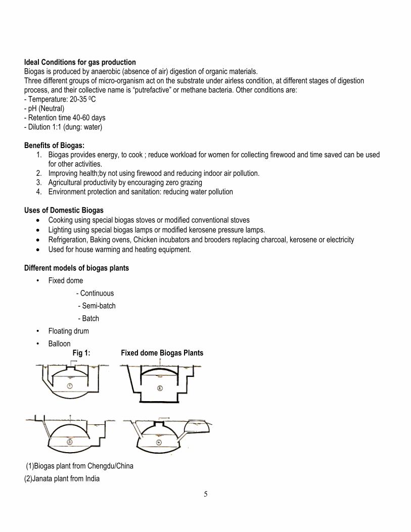
• Used for house warming and heating equipment. Different models of biogas plants
• Fixed dome
- Continuous
- Semi-batch
- Batch
• Floating drum
• Balloon Fig 1: Fixed dome Biogas Plants
(1)Biogas plant from Chengdu/China
(2)Janata plant from India
B

6
(3)Dheenbandhu plant of AFPRO from India
(4)Modified BORDA from Burundi Different Components of a biogas Plant
The cylindrical and hemispherical masonry structure, that is constructed underground following specific vertical and horizontal dimensions as per respective technical drawing details.
It consists of:
� Dung and urine mixing chamber (connecting a shed and digester)
� The digester for anaerobic digestion
� The slurry outlet and man hole � Expansion or compensation chamber with over flow � The slurry canal � Slurry storage pit
How the biogas plant operates
The plant feeding is done through inlet pipe into the digester, where an anaerobic digestion occurs, this internally built gas pressure pushes digested slurry out through an outlet opening to the expansion chamber and finally out through an over flow point and slurry canal.
CHAPTER 2: SIZE SELECTION
Guideline for the selection of the proper size of the biogas plant: Sizing follows three parameters: daily feed, retention time and digester volume Consumption based on 60 days hydraulic retention time & ambient temperatures 20 – 250c Given: 1 cow produce an average of 15 kg. of dung per day
Mixing ratio of dung to water/urine = 1:1 1 kg. of cow dung produce 40 litres of gas per day 2 cowsx15kg/day=30kg/day Dilute at ratio 1:1=30kg/dayx2=60litres Retention time of 60 days; 60litresx60 days=3600 litres Volume=3600/1000=3.6m3 ≈4m3
No. of normal adult animals
Digester size (m3)
Cows
Daily dung Feeding (Kg)
Water / Urine To mix with Dung (Lts)
Number of H/H Stoves & running time at a rate: 200 -350lts/hr.
Number of Lamps & running time at a rate: 120 - 180lts/ hr.
4 1 - 2 30 30 1 (For 3 hours)
1 (For 2 hours)
6 3 - 4 44 44 1 (For 4 hours)
1 (For 4.5 hours)
9 5 - 6 70 70 1 (For 6 hours)
2 (For 3.5 hours)

7
Observations:
� If cows are out-door grazed, multiply with 3 the number of cows. � Pigs manure can equally be used and provides even more gas than cow dung. � Kenyan household uses around 6 hours for cooking.
Looking for client personal information: � Clients energy requirement � Clients priority plans and future prospects � Number of people who are to be served � Number of people or animals-determines the amount of organic material available for feeding the plant daily � Animal rearing system � Slurry use discharge � The size of the farm for slurry use � Hygienic and sanitation conditions to be achieved � Biogas plant costs-affordability by the client
Selection of appropriate size of Biogas Plant based upon dung availability Considering many factors already discussed at this point, it is easy to decide the size of the biogas plant to be
installed, domestic biogas plants standards (4m3, 6m3, 8m3 10 m3 or 12m3), the quantity of daily feeding materials and the pre-determined hydraulic retention time (HRT) of 60 days will eventually guide the digester volume. CHAPTER 3: SITE SELECTION
Sites selection for BGP � Site should be convenient as possible to feed the digester. � Consider existing structures at the Site and how they can be incorporated in the biogas system e.g. cowshed,
kitchen stove etc. � Consider the terrain-ground level, the existing natural slope if it allows slurry to flow by gravity. A level ground will have a different approach from a ground with a defined slope. Where there is no slope, the slurry will be considered for drying or composting. � Consider infrastructures around the site like roads, pipeline, rivers, rocks, obstacles like big trees etc. � Consider the gas utilization points in terms of distance and slope, so that costs are reduced in piping material and
water trap provisions. � Consider clients future plans, like house expansion, new house construction increasing number of animals etc.
Where these structures don’t exist, and a biogas plant is required, it is necessary to consider them in the initial planning, such structures ease the work for dung collection, mixing with water and feeding
Cowshed or Pigsties
Depending on the cowshed or pigsty which should be connected to the plant, the direction for slurry flow should be established, in case of agricultural plant connected to toilets, it doesn’t only solve the problem of emptying the filled up pits, but also brings about a better and safe use of human wastes for agricultural production. It is important that the slurry out let is always at a lower point than the plant. After these considerations, laying out of the biogas plant can be done.
13 7 - 8 104 104 1 (For 6 hours)
3 (For 6 hours)
8
CHAPTER 4: CONSTRUCTION A. Types and quality standards of construction materials
CEMENT Cement should be good and high quality Portland cement from a brand with a good reputation should be stored 20 cm away from any walls. SAND Sand should be clean and not contain soil or other material; dirty sand will have a very early negative effect to the structure. Coffee wire should be used to remove any unwanted materials. Coarse and granular sand are suitable for concreting work, however fine sand should be used for plastering works. River/lake sand is well graded hence preferred. Avoid dusty sand. GRAVEL/BALLAST The size of gravel should neither be very big nor very small and should be clean, hard and angular in shape. If dirty should be cleaned first before use and the maximum size of gravel should be ¾” or ¼ the slab thickness BRICKS Bricks should be of high quality, made in the size of 23cm by 11cm by 7cm and the brick should be well burnt, straight, and regular in shape and size. In some area that you cannot burn, you may use bricks made of cement of the same size at the ratio of 1:8. Quantity requirements of construction materials (BOQs) refer to the appendix
B. Process Methods of laying out of Biogas Plant
1. Locating of suitable position for the biogas chamber 2. Fixing the relative positions of mixing chamber / inlet, digester, manhole, expansion chamber and slurry pits. 3. Using the respective drawing and their horizontal dimensions and add 45cm to the digester and expansion chamber
radii to allow working area for the wall and plaster. 4. Using Colour powder to indicate demarcation
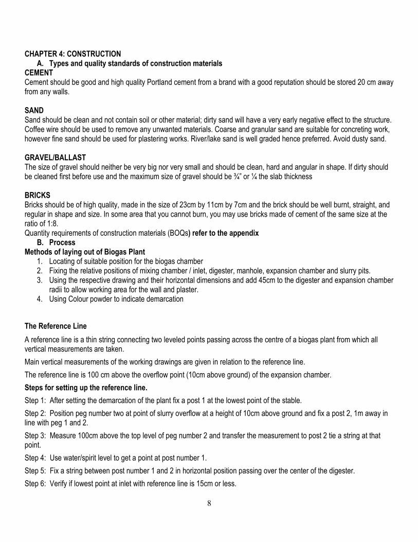
The Reference Line
A reference line is a thin string connecting two leveled points passing across the centre of a biogas plant from which all vertical measurements are taken.
Main vertical measurements of the working drawings are given in relation to the reference line.
The reference line is 100 cm above the overflow point (10cm above ground) of the expansion chamber.
Steps for setting up the reference line.
Step 1: After setting the demarcation of the plant fix a post 1 at the lowest point of the stable.
Step 2: Position peg number two at point of slurry overflow at a height of 10cm above ground and fix a post 2, 1m away in line with peg 1 and 2.
Step 3: Measure 100cm above the top level of peg number 2 and transfer the measurement to post 2 tie a string at that point.
Step 4: Use water/spirit level to get a point at post number 1.
Step 5: Fix a string between post number 1 and 2 in horizontal position passing over the center of the digester.
Step 6: Verify if lowest point at inlet with reference line is 15cm or less.

9
Step 7: If more than 15cm reposition peg number 2.
Step 8: Indicate both center point for digester and expansion chamber on the reference line by fixing small nail on those points.
In order not to lose the level of the reference line it is advisable to also mark it on a tree or building near to the plant.
In case of slope setting of reference line should be along a contour or across the slope. The same 10cm is applied in slope situation.
Displacing the reference line will influence negatively the amount of gas to be stored, the pressure and the slurry movement. Tools: pegs, string, nail, spirit level/water level
The Radius Stick and its importance in the dome construction
This is a guide stick, measured specifically for controlling the radius of the digester and controls the bricks in spherical shape while constructing. This gives the measurement from the radius point to the inner wall of the hemispherical digester.
The radius stick end can spin around the nail or round iron bar and can be fixed with binding wire or manila rope.
� How to make a radius stick:
Several ways can be applied, whereby the radius of the digester is marked by a nail at the length of this piece of timber, alternatively steel or bamboo can be used.
The importance of the radius stick is to ensure that all blocks and bricks go round on a given radius and it makes a round and a dome shape.
Methods of digging the pit
Pit digging depends on the digester size. The radius of any digester is increased by 40 - 45cm to allow working area around the digester. Where ground water table is high, a small pit is dug aside the digester pit to allow water to collect so that it can be removed manually or pumped out when digging continues.
Soil scooped from the pit should be placed at least one meter away from the edge of the pit.
It is advisable that digging should not be done during rainy seasons and dig a cone incase of loose soil. Tools: Radius stick, peg, plumb bob, spade, mallet Fixation of the centre point
For the construction of the wall and dome, a GI pipe is fixed at the radius point and defined in the middle of the excavated pit below the reference line. The distance to the reference line is given in the drawing. From the center point use radius stick to get the diameter. Tools: Radius stick, peg, plumb bob, string Casting concrete of Foundation base
Step1: Using a radius stick establish the slab ring.
Step 2: level the base and incase of a cone, dig the depth according to drawing.
Step 3: establish the slab height by use of pegs leveled by a spirit level. Step 4: Pouring concrete on the slab to a depth of 75mm together with the floor of the digester.
Step 5: Using the radius stick immediately lay one or more courses of bricks/blocks
Step 6: The first course of bricks is laid at half brick while the rest are laid quarter brick.

10
The mortar ratio of 1 cement to ¼ lime to 4 sand (1:1/4:4). Or lay blocks in the normal way
It is important to use the technical drawing from the beginning in order to have all the dimensions in place. Tools: Radius stick, brick trowel, spade, hoe, wheel barrow, measuring boxes Construction of a wall.
1. All the stones/blocks/bricks are dipped in water to clean and improve binding before they are used for construction.
2. Lay the bricks in a quarter positions guided by the radius stick as a gauge for the 1st 3 courses then lay bricks normally for rest of the courses OR lay the blocks normally.
3. Construction of slurry outlet manhole of 60 cm is done simultaneously. Use spirit level or plumb bob to ensure vertical walls.
4. Reserve space to position inlet pipes while constructing.
The stones/blocks/brick wall should be watered in order to remove all the dust and loose particles to allow strong bonding of the mortar in between. Tools: Radius stick, spade, brick trowel, bucket, hoe, wheel barrow, measuring boxes
Fixing of inlet pipe(s)
The plastic pipe of 10 cm. diameter is placed into the digester wall at a position which should be 300mm. from the floor slab.
Position the inlet pipe of the mixing chamber directly in line opposite the slurry outlet manhole opening.
In case of a toilet connection of the toilet pipe can be installed lower than the inlet pipe from mixing chamber but it should not go above the lower slurry level to avoid gas escape through the toilet
Toilet attachment to the plant need to be constructed with a pan without siphon or trap to avoid excessive water inside the digester affecting the hydraulic retention time and total solids in the slurry. It is also not possible to de-block the pipe if siphon is placed. The inlet pipe from the toilet should not discharge farther than 30° from the hart-line. Additionally the pan level of toilet should at least be 60 cm above the overflow level in the outlet walls.
Note that this pipe connects the digester and the mixing/dung chamber at the cow shed, it is inclined at an angle direct to the centre of the digester and reinforced with concrete/mortar on the outside. For details see the technical drawing:
Building the dome: Dome construction starts where the wall ends. Note: there is no dome ring beam Step 1: prepare a form work to support the bricks on the slurry outlet, allowing space to pass in and out. Step 2: prepare a radius stick of dome radius as in drawing and fix to the centre pipe; the opposite end should have a nail fixed at 90˚ to the stick. Step 3: lay mortar on the wall and shape to assume the dome shape according to the radius stick. Lay the bricks on the mortar bed one by one making sure each brick is at right angle to the stick. Step 4: continue similarly making sure that the next course starts 1 brick away and hooking of brick is done whenever instability is noticed in setting. Continue similarly until bricks close to a dome. Step 5: before closing the brickwork, install the dome gas pipe and support as necessary. See below Tools; Radius stick, spade, brick trowel, bucket, hoe, wheel barrow, measuring boxes and hooks. Plastering the digester wall.
- At the inside of the digester plaster with ratio of 1: ¼:4 with a depth of 2cm and wall should be washed with cement water before plastering.
Backfilling lower part

11
Soil backfilling and compaction around the lower part of the digester should be done up to 3 courses lower. Compaction is done between 30 – 60cm and water is added to bring more compaction. Soil compaction is important, and it must be properly done because once the digester is in use, the block/brick wall is subjected to high pressure from inside, and therefore it must be supported from the outside.
Curing of wall To avoid cracking and encourage binding, routine sprinkling of water needs to be done during 5 to 7 days. Fixation of dome gas pipe
� Note: Fixation of dome gas pipe is done before plastering inside of the digester. Step 1: Thread one end of a piece of galvanized pipe of 1-1.5 inch and a length of 41 cm and mount a T-joint. It is advisable to grease the thread in advance to prevent corrosion. Step 2: Weld a disc and some scrap pieces of iron bar 4 cm on the other end of the galvanized pipe. Step 3: Join the other components of the testing unit to the galvanized pipe. Step 4: Provide temporary support below the testing unit. Step 5: Position the pipe with the testing unit side above on top of the digester. See diagram Step 6: Reinforce with concrete of the mixture (1:3:3) including 2% of water proof cement. Step 7: Place main gas valve on the test unit. The disc prevents gas from escaping along the pipe wall and iron bars, act as an anchor and gives additional strength to the pipe fixed in the brickwork.
Under normal operation the T-joints should remain sealed and closed with plugs, and all threads are joined with seal/thread tapes, which as a rule of thumb should be applied in approximately eight turns.
The test unit chamber, is where gas leakage testing, measuring of gas pressure in the digester and gas flow/consumption rate is normally conducted, and from this place pipes are laid and connected direct to the consumption point. Tools: Grease, Seal tape, portable pipe vice, hacksaw / wheel cut, measuring tape, thread machine, main gas valve, wire brush, pipe wrench, screw driver and oil can. Plastering of the upper part of the digester (gas storage)
The outside upper part of the digester is plastered first using similar ratio as the lower part. After installing the gas outlet pipe, plastering of the gas storage area inside the digester starts in the following sequence (7 coats to be applied):
1. Wall washing using cement water 2. Plastering 1 centimeter cement + sand (1:2.5) 3. Wall washing with cement water 4. Plastering 1 centimeter cement + lime + sand (1:¼:2:5) including water proof cement at 2 kg per 1 bag
of cement. 5. Wall washing with cement water + water proof cement ratio as above. 6. Plastering cement + sand (1:2.5) the cement with a mixture of water proof cement ratio as above. 7. A paste of cement (cement screed or neru) + water proof cement as above.
Sand for use in the gas tight plasters should be well sieved and it should not contain any dust/dirt. The 2nd and 3rd plasters have to be done consecutively in not less than 48 hours from one another. After the plant construction work, floor work and plastering, the plant is supposed to be in moist condition in order to allow curing to take place. The plant will be ready for initial filling 2 weeks after finishing the final plastering. Expansion/compensating chamber construction
The function of the expansion chamber is to store the digested slurry and for this matter to develop pressure inside the plant.

12
The slurry out let manhole between the digester and the expansion chamber allows slurry to flow in and out following the gas use and gas production respectively .
- The foundation for the expansion chamber is made out of concrete at the ratio of (1:3:4) or (1:2:4) depending on the size of aggregates.
- Set out the foundation according to the drawing and set the 4 corners of the walls checking the diagonals for square-ness
- Build the walls up to required height leaving overflow opening at the correct height from the reference line. - Apply plaster accordingly at a ratio of 1:5 after at least 1 day waiting.
Construction of Mixing Chamber
The mixing chamber is constructed to mix dung and water and make the required paste.
• The foundation of the inlet pit should be placed in well rammed, hard and levelled surface.
• In this rammed surface first of all the rectangular base of mixing chamber is constructed. The height of the base should be decided in such a manner that the floor of the mixing chamber is at least 10 cm above the outlet overflow level.
• The circular mixing chamber measurements are 600mm diameter x 600mm. high
• The proposed minimum urine collection chambers measurements are 55cmx80cmx20cm.
• After brick laying is done, after at least 1 day waiting, both inside and outside of the chambers are plastered with cement mortar (1 part of cement to 4 parts of sand).
CHAPTER 5: PIPING: Fixation of pipeline alignment and digging of trench The piping system of a fixed dome digester can be several hundred metres long. The pressure of the digester is enough to transport the gas required for normal cooking. The piping system is a crucial part of biogas technology and to be established with maximum care. All outside piping (main gas line) is done in 1” to ¾” to ½” class ‘C’ PVC-plastic or galvanized steel pipe or PPR pipes. The selection which type of pipe to be used is based on;
� distance to the utilization points � Type of soils, salinity of soil will corrode steel pipe. � affordability � convenience � availability
Step 1: Trench digging minimum 45 cm depth and 35 cm width for both PVC-plastic pipes and galvanized pipe. Step 2: Connect the main line with the testing unit. Step 3: Determine the position of the water drain, establishing a water drain valve at a T-joint mounted at the lowest point along the pipeline. Just before the drain valve, an extension of about 25 cm. ½” pipe pointing 45 degrees downward should be employed. Step 4: Construct protection chamber for the water drain valve, 50cmx50cm include a cover with lid. Step 5: Fixation of piping to the wall of the house near the utilisation point. Step 6: Backfilling the piping trench. Draining should be carried out regularly, i.e. once in a month Tools; Grease, Seal tape, portable pipe vice, hacksaw / wheel cut, measuring tape, thread machine, water drain valve, wire brush, pipe wrench, screw driver and oil can. Bio-gas sites differ from one another due to different terrain and nature of topography to the gas consumption point i.e. variable slopes.

13
Such earmarked features include: 1. Flat terrain (level grounds), 2. Slope towards the consumption point, 3. Slope towards the bio-gas plant and 4. In case of long gas pipe line (depending on the topography of the respective site), the ground tends to be undulating, thus going up and down. The following drawings illustrate the right position for the water drain installation: preferably the drain valve should be mounted either just after the plant or before the consumption point.
1. Slope towards the bio-gas plant
Figure 1: Piping system with straight slope from kitchen to digester. No water trap required as condensation water drains into the digester
2. Undulating terrain

14
WATER TRAPS

15
Figure 2: Wherever condensation water cannot drain back into the digester, a water trap becomes necessary.
Figure 3: Automatic water trap: (1) T-joint in the piping system, (2) water column, equal to max. gas pressure + 30% security, (3) solid brick or concrete casing, (4) concrete lid, (5) drainage
Figure 4: Manual water trap: (1) T-joint, (2) buffer storage for condensated water, (3) manual tap, (4) casing, (5) concrete lid, (6)

16
drainage The asymmetrical U-trap is the best option in terms of cost and operation. The advantages include:-
Minimum 140 cm 120 cm
No housing chamber is required
i) Incase of problems, the customer can easily help himself.
ii) Only made out of standard fittings
iii) No block sensitive against surface water and erosion.
iv) Less digging work during installation
v) Less material required
NB: The installation requires careful planning especially if the max pressure of the plant is not standardized.
CHAPTER 6: FINISHING WORKS Finishing works � Fabrication of all chamber and manhole lids
o The lids should take the shape of the intended opening o The size of the lid must be flush with the outside wall of the intended opening o The thickness of the lid must be at least 7cm.
The following steps are for fabrication of the lids:- Step 1: Set the base out of plastic or used cement bags on a flat ground Step 2: Use Bricks or a mould can be used to make the desired shape Step 3: Use Welded mesh (resting on small stones) is used as the reinforcement and 8mm round bars are used to make the handles. The handles are fixed to the weld mesh using a binding wire. The lengths of the handles is about 8cm.
Diagram 3

17
Step 4: Mix Strong mortar in the ratio of 1:3 cement: sand. Step 5: Pour Strong mortar in the mould and allow setting for 7 days.
� Cleaning inside the digester and expansion chamber � Landscaping- Make the place look attractive e.g. plant flowers or grass. � Clean all the tools and equipments used � Propose the improvement of the cow shed to the farmer if needed. � Construction of toilet if needed. � Proper disposal of debris. INDOOR PIPING Reduce the size from ¾” to ½” and pass it through a hole in the wall to the respective consumption point (s). Installation of appliances Biogas is denser than air therefore a biogas lamp is installed in downward position to facilitate gas combustion. Biogas needs a lot of air to burn, the burner must have air rationing mechanism to control the amount of air. Biogas contains about 35% Carbon dioxide and therefore does not explode in a flame with air. Fixation of gas taps, rubber hosepipe, stove and lamps:
Gas lamps are usually hung on walls or at the roof ceiling depending on the type of lamp. A gas valve is also provided to control the gas flow as well as the brightness, turning the device on and off. The lamp should NOT be installed directly above the stove area due to risk of contamination Stoves at the kitchen are connected to the gas line by using flexible hose pipes and put on a table or down on the floor, depending on the user.
Checking for leakages After installation each section of the piping system has to be pressure tested for gas leakages. For this purpose a pressure indicator has to be used. Basically it consists of a mouthpiece to blow pressure in the piping system and a transparent plastic U-pipe, which has two sides of more than 1 m length. The pipe is filled with water and installed in the kitchen. The set-up is connected to the T-joint at the test unit chamber, which is along the pipe line. All ends of the piping system are closed and air is blown into the mouthpiece until the water in the transparent hosepipe develops to a level difference of 1m. If this level difference remains constant, the pipe line is gas tight. When the pressure drops, there must be a leakage somewhere, which has to be detected and fixed before the work on the piping system continues. To detect a leakage, brush and soap water are used, in case of a leakage soap bubble will be formed. Leakages occur mainly at joints, unions and particularly where hosepipes are connected to the fixed piping system. Such weak points need to be minimized and tightened. Function of Test Unit Chamber The test unit chamber is used for the quality management by the domestic biogas programme. Apart from pressure measurements, leakage detection in the piping, the test chamber is used for determining the amount of gas in use through an installed gas meter. The gas meter measures the amount of gas which goes through it when going to the use points. The gas meter measures in m3/hr. The gas meter is connected to the two T fittings at the test chamber by-passing the gas valve so as to allow gas flow when in use.

18
Drawing No. 8 An area for monitoring the plant performance & gas leakage.
1. Test unit chamber with lid 2. Main gas valve 3. A T fitting connected 4. A second T-joint. 5. Measuring of the plant gas pressure. 6. Pressure indicator-Manometer 7. Nos 8,9,10,11 shows how the line should be tested for leakage 8. No 12, 13 and 14 shows gas flow and consumption rate.
Some new technologies and modification of gas appliances Special biogas lamps and stoves are provided at a cost by the programme. Conventional LPG using appliances like lamps, stoves and refrigerators can be modified to use biogas. Different engines using diesel or petrol can be modified to utilize biogas. All modifications should be done by skilled technicians. Gas Utilization Decisive parts of a gas burner are the
• Jet or nozzle,
• Primary air intake
• Secondary air access of the flame to.

19
• Exhaust gas, which has to disappear from the flame without hindering the secondary air to reach the flame. The flame can be adjusted comfortably to be stable and not too wind sensitive under the bottom of the pot. The highest adjustment of the stove knob should not lead to a flame, which leaks around the pot and burns the plastic handles. The performance of the flame depends among others on the quality of the gas, the altitude of the location and the gas pressure in the digester. For the performance tests, the flame burns better if a pot filled with water is sitting on the pot rest (or a bit above). The sketch shows the different parameters on the flame. The example shows the ideal case, small blue flames; completely under the pot … best energy efficiency.
Example of some Biogas consumption rates in various applications
� Cooking: Between 150 – 250 Its. of biogas are used in 1 hour for boiling 1 liter of water, depending on the efficiency of the burner. � Lighting: Between 120 – 180 Its. of biogas are used in 1 hour, a biogas lamp produce light equivalent to a 75 watts bulb. � Heating and industrial burners: Between 450 – 500 lts. of biogas is used per one hour. � Refrigeration: Refrigerators with 100 lts capacity can run on between 30 – 80 lts of biogas per hour. � Engines (Motive power): 420 lts of biogas can be used in 1 hour. To produce electricity of 1kWh 700 lts. of biogas is required.
CHAPTER 7: OPERATION OF THE BIOGAS PLANT:
Primary air
Jet or nozzle
Secondary air
Gas/Air mixture

20
Filling up of the digester with feedstock The initial feeding of digester is done immediately after 21 days from the last layer of plastering. cow dung should be collected before and during the construction of the biogas plant. While filling the digester make sure that the cow dung is clean without containing sand, trash, wood, grass, household waste, goat/sheep droppings and other impurities. Such materials will enter the digester and form a scum layer blocking the gas to rise and enter the gas holder. The dung is mixed with urine and / water at the ratio of (1:1) While mixing cow dung with water, remove all the unwanted material mentioned above. The digester is filled daily with the quantity of cow dung and water described to have maximum gas production. CHAPTER 8: SLURRY UTILIZATION: Definition: This is a product obtained after manure is digested in a biogas plant. Slurry usually flows out of the expansion chamber in large quantities at night due to the accumulation of pressure caused by unused gas overnight. Gas pressure tend to displace the slurry in the digester/dome by pushing it out through the expansion chamber. Composition of biogas slurry. Biogas slurry is composed mainly of the following;
1. Solid plant materials. 2. Water. 3. Nutrients i.e. ammonia (NH4), nitrogen and phosphorous.
Uses of biogas slurry. Slurry is used as;
1. Manure for crops. -improves soil fertility. -improves crop production.
2. In fish ponds to enhance the growth of algae. It has been found to be better compared to the raw manure. 3. Used as a partial supplement in the rations of pigs and fish meal.
Importance of biogas slurry.
1. It contains essential nutrients like Nitrogen and phosphorous that is good for plants. 2. Reduces the cost of buying chemical fertilizers.
Slurry distribution and application methods.
1. Open trenches –slurry will flow to the farms through gravity. 2. Manually using wheelbarrows and buckets –in this method, wheelbarrows/containers must have lids since the
slurry is in liquid form. 3. Mechanically –tankers fitted to lorries or pulled with tractors are used & Pumping systems –use of pipes
CHAPTER 9: TROUBLE SHOOTING Potential problems and likely solutions (ex. Slurry in the pipeline)
Problem Possible causes Remedies:
Insufficient gas pressure, max. plant pressure not reached
Gas leakage along the pipe line, Under feeding of the plant.
Check for any gas leakage and solve the problem, -Ensure the feeding instruction is followed,

21
and daily feeding is carried out
Gas not enough as it used to be before
Underfeeding of the plant, Possible leakages through gas tight zone, Possible gas leakages along the pipe line, Scum formation inside the digester, Dung/water mixture not at the right proportion to the one incorporated in the digester design, Siltation-accumulation of inorganic solids inside the digester.
Ensure the feeding instruction is followed and daily feeding is done for a constant gas production, - Check for gas leakages and gas tightness inside the plant, when necessary emptying of the plant should be performed in order to inspect and solve the problem.
Bio-effluent smelling at the expansion chamber & canal
Over feeding of the digester,
- Feeding instruction to ensure a good consistency of the mixture should be followed
Gas stove not burning well Blocked primary air ducts, Blocked flame holes, Incorrect gas/air mixing ratio Presence of water in the pipe line, Poor stove design
- Clean all the air ducts and burner holes regularly to prevent blockages, - Adjust the primary air knob in order to get the right mixture, - Open the water drain valve to remove any water condensed inside. - Purchase better stove
In case of lamp does not give bright light
Dirty glass screen, Cracked or destroyed mantle, Incorrect gas/air mixing ratio, Presence of water in the system Blockage of the mantle holder hole
- Clean the lamps glass screen regularly, - Replace the cracked mantle, - Adjust the primary air knob in order to get the right mixture, - Open water drain valve to remove any water. - Clean the mantle holder hole
Maximum gas pressure achieved but still gas quantity is not as expected
Under feeding or irregular feeding Scum formation inside the digester
- Ensure that daily feeding is done in sufficient quantity, - Ensure that mixing is done properly and all the unwanted material are removed - Empty the plant, remove the scum and stir the inside slurry
No any gas reaching the appliances
Water has blocked the gas passage along the pipe line, No any gas being produced inside the digester, Disconnected gas pipe line, Inhibiting substances have entered into the digester, Closed main gas valve at the
- Check for the presence of water along the gas line and drain it - Check for gas leakages in the pipe line and solve them - Check for any pipe disconnection and reconnect it - Check the main gas valve and reopen it - Remove the inhibiting substances or

22
test unit chamber.
chemicals from the digester
The feeding materials not entering into the digester
Blocked inlet pipe, Position of the inlet mixing chamber placed below the overflow point.
- Poke through the inlet pipe, - Ensure right vertical dimensions are used to avoid wrong placement of the mixing chamber.
Bio-effluent too thick at the overflow
Incorrect dung/water mixing ratio (less water/urine), No hydraulic movement inside the digester, Water leakage on the lower part of the digester, Water leakage at the expansion chamber base
- Ensure good mixing consistency at feeding, - Check for water leakages inside the plant and expansion chamber and seal them off - Make sure that the gas is used daily to allow hydraulic movement to take place inside the digester. - Empty the plant and seal the cracks or renew the base
Slurry entering the gas pipe line
Gas outlet pipe placed below the over flow point
- check slurry overflow point if it is not / or was blocked. - reduce slurry overflow point to a lower level.
If problems persist, contact the Programme Office. CHAPTER 10: ROLE OF KENDBIP Supervision and monitoring visits by the Programme. The programme staff will always be checking biogas plants under different stages to ensure that quality is maintained. The 3 following stages are checked;
1. Under construction 2. Plant commissioning 3. After sale service
Domestic biogas programme staff will check plant under construction for the following issues; • Presence of Sales contract • Quality of material used • Center to Center distance digester – expansion chamber • Check radius stick (wall, & dome) • Check radii wall, dome, height of wall, dome & exp. chamber • Reference line • Lower slurry level – bottom • Inlet pipe(s) height & direction • Plaster ratios and thickness (2 cm) • Floor concrete quality • Location / layout of plant
– Kitchen / stable / slurry flow / water – Presence of shade over the biogas plant or presence of roots from trees – Reference line/stable floor /inlet floor
Programme staff will provide feedback to masons and users of their findings.

23
APPENDIX A. FORMS
The following forms are relevant for masons within the domestic biogas programme; - contract between KENDBIP and mason - contract between mason – client and KENDBIP - Plant completion report. - After sales service report
KENBIM LIST
ITEM DESCRIPTION 4m3 6m3 8m3 10m3 12m3
A General bulk Materials UNIT QTY QTY QTY QTY QTY
1 Cement-50 kg bags 13 17 20 22 27
2 Water proof cement-1kg bags 3 4 5 6 7
3 Quarry stones dressed/Blocks-390x190x150mm pcs 145 180 220 270 290
4 Bricks-230x110x70mm pcs 180 260 300 340 400
5 Sand tonnes 3 4 5 6 7
6 Ballast-25mm-1" tonnes 2 2 3 4 4 7 Lime 25kg bags bags 4 5 6 7 8
8 Round bar-R8 lengths 1 1 1 1 1
9 Weld mesh- heavy gauge Pcs 1 1 2 2 2
10 Binding wire Kg 1 1 1 1 1
Sub Total 1
B Piping fittings + Assorted items
C Labour cost
D Excavation &site preparation
E After sales service& Guarantee 1 yr
GRAND TOTAL
KENBIM Domestic Biogas Plant installation 4m3
Bill of Quantities&Pricing-Ngugi Kimwaki
1 Construction Materials QTY UNIT RATE Household Mason/Co. KENDBIP
1.0 Cement-50 kg 17 bags
1.1 Water proof cement-1kg 4 bags
1.2 Quarry stones dressed(6X9) 0.5 lorry
1.3 Bricks-230x110x70mm 200 pcs
1.4 River Sand 0.5 lorry
1.5 Ballast 1 tonnes
1.6 Ballast chips( 1/4" ) 1 tonnes
1.7 Lime 25kg bags 25 kgs
1.8 Binding wire 2 kg
1.9 Timber-2"x2" 2.1 m
1.10 Plywood-3mm 1 sheets
1.11 Nails-3" 0.5 kg

24
1.12 Nails-2" 0.5 kg
1.13 GI pipe-3/4" 1 length
1.16 PVC Pipe 4"-Sanitation 1 length
1.17 welded/sq mesh(G8) 2 pcs
2 Piping Materials
2.1 Dome pipe-3/4"-410mm 1 pcs
2.2 GI Ballcork-3/4" 1 pcs
2.7 Biogas Lamp 1 pcs
2.8 Burner-Single 1 pcs
2.9 Burner-Double 1 pcs
2.10 Pressure manometer 1 pcs
2.11 PVC pipes-3/4" 4 pcs
2.12 PVC T-joint 2 pcs
2.13 PVC Reducer-3/4"x1/2" 1 pcs
2.14 PVC Pipes-1/2" 1 pcs
2.15 GI Elbows-3/4" 2 pcs
2.16 PVC Elbows-1/2" 2 pcs
2.17 Reducer 1"x3/4" 1 pcs
2.18 Hexagonal nipples-3/4" 2 pcs
2.19 PVC Socket-3/4" 1 pcs
2.20 GI T-joint 1/2" 1 pcs
2.21 GI Socket-3/4" 1 pcs
2.22 Hexagonal nipples-1/2" 1 pcs
2.23 GI Reducer-1"x3/4" 1 pcs
2.24 Tangit glue-50ml 1 pcs
2.25 GI Ballcork-1/2" 1 pcs
3 Labour
3.1 Excavation & site preparation 1 l/s
4 Company services & fee
4.1 Construction fee 1 l/s
4.2 Guarantee & after sales service(1 yr) 1 l/s
Grand total
NOTES:
1 The value of material available on site is ………………………….. As witnessed by…………………………………………………….

25
2 Date witnessed……………………………………………
B. ROLES OF MASON:
1. The masons will be responsible for identifying the client. 2. Initial site visit to determine the feasibility for biogas plant. 3. The masons are responsible for filling and sign contract and bill of quantity (BOQ). 4. Proper lay out of site for excavation. 5. Supervising site preparation and standard of quality of materials. 6. Construction and installation. 7. Inform the client about proper feeding and operation of the biogas plant and appliances. 8. Filling and signing of the plant completion report. 9. Provision of after sale service. 10. Report to supervisor any problems that need the domestic biogas programme support. C. ROLES OF SUPERVISOR: 1. Ensure quality construction by regular site visits. 2. Counter sign the plant completion report. 3. To respond to the request from a mason to assistance. 4. Advise/assist masons on proper filling of different forms. 5. Promoting domestic biogas in the district. 6. Train end users on proper usage and taking care of biogas plant. D. PROMOTION AND MARKETING: The programme will work with local authority and NGOs to promote domestic biogas in the entire district that the masons are working in. � Develop and distribute promotion material. � Train and assist local promoters and provide incentive for identification of clients. � Supervisors might assist masons in visiting clients � Programme provide subsidy to make domestic biogas more affordable. E. USER MANUAL
HANDED DURING COMPLETION REPORT SIGNING Purpose: to link the programme to the user Information on topics such as:
• cowshed
• The plant(what could be possible problems with possible remedies recommended to the user)
• piping problems
• Appliances
• Slurry use
• Masons
• Supervisors
• One page poster with main uses
• Bio-slurry use and management
• After sales service, warranty period and details of what the user should expect out of that period
• Common mistakes