kentucky best management practices for construction activities...
TRANSCRIPT
KentuckyBest Management Practicesfor Construction Activities
2005
Environmental and Public Protection Cabinet
Division of ConservationAndDivision of Water

Kentucky Best Management Practicesfor Construction Activities
Funding for this project was provided in part by a grant fromthe U.S. Environmental Protection Agency (USEPA) through theKentucky Division of Water (KDOW), Nonpoint Source Sectionand the Kentucky Division of Conservation (KDOC) to TetraTech, as authorized by the Clean Water Act Amendments of1987, Section 319(h) Nonpoint Source Implementation Grant# C9994861-01. Mention of trade names or commercialproducts, if any, does not constitute endorsement. Thisdocument was printed on recycled paper.
Technical Review Committee
Tom Gabbard – KY Division of WaterJennifer Thompson - KY Division of ConservationStephen Bowling – KY Transportation CabinetRay Werkmeister – KY Transportation CenterKurt Mason - Natural Resources Conservation Service Charles Farmer – Natural Resources Conservation ServiceMary Kathryn Dickerson - Boone, Campbell, and Kenton County Conservation DistrictsDavid Carroll – Lexington-Fayette Urban County Government, Division of EngineeringDavid Johnson, Louisville-Jefferson County Metropolitan Sewer DistrictJohn Lyons – Sanitation District No. 1 in Northern KentuckyJeff Lashlee, - City of Bowling GreenJames Kipp – KY Water Resources Research InstituteLindell Ormsbee – University of Kentucky, Tracy Farmer Center for the EnvironmentBarry Tonning, Tetra TechRichard Walker, Tetra TechJohn Kosco, Tetra TechWilliam Marshall, Tetra Tech
This document has been approved by the Kentucky TransportationCabinet, and reflects Best Management Practices for erosion andsediment control for highway construction projects.
ContentsIntroduction . . . . . . . � 1
Erosion, Sediment, and Water Quality Impacts . . . . . . . . . . . . . . . . . . . . . . . . . . . . . . . . . . . . . . . 1
Purpose of the Manual . . . . . . . . . . . . . . . . . . . . . . . . . . . . . . . . . . . . . . . . . . . . . . . . . . . . . . . . . . 2
Principles of Construction Site Runoff Control . . . . . . . . . . . . . . . . . . . . . . . . . . . . . . . . . . . . . . . 3
Low Impact Design . . . . . . . . . . . . . . . . . . . . . . . . . . . . . . . . . . . . . . . . . . . . . . . . . . . . . . . . . . . . . 4
LID Practices . . � 5
References . . . . � 7
Regulations and Requirements . . . . . . . . . . . . . . . . . . . . . . . . . . . . . . . . . . . . . . . . . . . . . . . . . . . 8
Federal and State Stormwater Permit Requirements . . . . . . . . . . . . . . . . . . . . . . . . . . . . . . . . . . . 8
Federal Requirements . . . . . . . . . . . . . . . . . . . . . . . . . . . . . . . . . . . . . . . . . . . . . . . . . . . . . . . . 8
KPDES Permit for Construction Activities . . . . . . . . . . . . . . . . . . . . . . . . . . . . . . . . . . . . . . . . . 8
ESC Plan Requirements for Local Governments in Kentucky . . . . . . . . . . . . . . . . . . . . . . . . . . . 10
Louisville – Jefferson County Metropolitan Sewer District . . . . . . . . . . . . . . . . . . . . . . . . . . . 11
Lexington-Fayette Urban County Government . . . . . . . . . . . . . . . . . . . . . . . . . . . . . . . . . . . . 11
Sanitation District # 1 in Northern Kentucky . . . . . . . . . . . . . . . . . . . . . . . . . . . . . . . . . . . . . 12
Other Phase II Stormwater Cities . . . . . . . . . . . . . . . . . . . . . . . . . . . . . . . . . . . . . . . . . . . . . . 12
Kentucky Transportation Cabinet (KYTC) . . . . . . . . . . . . . . . . . . . . . . . . . . . . . . . . . . . . . . . . . . 13
Related Regulations . . . . . . . . . . . . . . . . . . . . . . . . . . . . . . . . . . . . . . . . . . . . . . . . . . . . . . . . . . . . 13
Federal 404 Permit . . . . . . . . . . . . . . . . . . . . . . . . . . . . . . . . . . . . . . . . . . . . . . . . . . . . . . . . . 13
KY 401 Water Quality Certification . . . . . . . . . . . . . . . . . . . . . . . . . . . . . . . . . . . . . . . . . . . . . 16
KY Floodplain Construction Permit . . . . . . . . . . . . . . . . . . . . . . . . . . . . . . . . . . . . . . . . . . . . . 16
Stormwater Best Management Practices Plan . . . . . . . . . . . . . . . . . . . . . . . . . . . . . . . . . . . 18
BMP Plan Requirements . . . . . . . . . . . . . . . . . . . . . . . . . . . . . . . . . . . . . . . . . . . . . . . . . . . . . . . . 18
Plan Amendments . . . . . . . . . . . . . . . . . . . . . . . . . . . . . . . . . . . . . . . . . . . . . . . . . . . . . . . . . . . . . 20
Stormwater BMP Plan Checklist . . . . . . . . . . . . . . . . . . . . . . . . . . . . . . . . . . . . . . . . . . . . . . . . . . 21
Construction Site Inspection Checklist . . . . . . . . . . . . . . . . . . . . . . . . . . . . . . . . . . . . . . . . . . . . 23
BMP Symbols � 25
Best Management Practices . . . . . . . . . . . . . . . . . . . . . . . . . . . . . . . . . . . . . . . . . . . . . . . . . . . . . 27
BMP Selection Guidelines . . . . . . . . . . . . . . . . . . . . . . . . . . . . . . . . . . . . . . . . . . . . . . . . . . . . . . 27
Construction Entrance . . . . . . . . . . . . . . . . . . . . . . . . . . . . . . . . . . . . . . . . . . . . . . . . . . . . . . . . . 31
Diversion Channel . . . . . . . . . . . . . . . . . . . . . . . . . . . . . . . . . . . . . . . . . . . . . . . . . . . . . . . . . . . . . 33
Soil Stabilization . . . . . . . . . . . . . . . . . . . . . . . . . . . . . . . . . . . . . . . . . . . . . . . . . . . . . . . . . . . . . . 35
Temporary Seeding . . . . . . . . . . . . . . . . . . . . . . . . . . . . . . . . . . . . . . . . . . . . . . . . . . . . . . . . . 35
Permanent Seeding . . . . . . . . . . . . . . . . . . . . . . . . . . . . . . . . . . . . . . . . . . . . . . . . . . . . . . . . . 37
Mulching . � 40
Sodding . . � 45
Topsoil Stockpiling . . . . . . . . . . . . . . . . . . . . . . . . . . . . . . . . . . . . . . . . . . . . . . . . . . . . . . . . . 48
Dust Control . . . . . . . . . . . . . . . . . . . . . . . . . . . . . . . . . . . . . . . . . . . . . . . . . . . . . . . . . . . . . . 52
Sediment Barriers . . . . . . . . . . . . . . . . . . . . . . . . . . . . . . . . . . . . . . . . . . . . . . . . . . . . . . . . . . . . . 53
Silt Fence . � 53
Brush, Rock, and Commercial Sediment Barriers . . . . . . . . . . . . . . . . . . . . . . . . . . . . . . . . . 56
Slope Protection . . . . . . . . . . . . . . . . . . . . . . . . . . . . . . . . . . . . . . . . . . . . . . . . . . . . . . . . . . . . . . 58
Erosion Control Blankets and Mats . . . . . . . . . . . . . . . . . . . . . . . . . . . . . . . . . . . . . . . . . . . . 58
Surface Roughening . . . . . . . . . . . . . . . . . . . . . . . . . . . . . . . . . . . . . . . . . . . . . . . . . . . . . . . . 66
Slope Drain . . . . . . . . . . . . . . . . . . . . . . . . . . . . . . . . . . . . . . . . . . . . . . . . . . . . . . . . . . . . . . . 69
Gabion . . . � 72
Cellular Confinement Systems . . . . . . . . . . . . . . . . . . . . . . . . . . . . . . . . . . . . . . . . . . . . . . . . 77
Polyacrylamides . . . . . . . . . . . . . . . . . . . . . . . . . . . . . . . . . . . . . . . . . . . . . . . . . . . . . . . . . . . 79
Inlets, Pipes, and Culverts . . . . . . . . . . . . . . . . . . . . . . . . . . . . . . . . . . . . . . . . . . . . . . . . . . . . . . 81
Curb Inlet Sediment Barrier . . . . . . . . . . . . . . . . . . . . . . . . . . . . . . . . . . . . . . . . . . . . . . . . . . 81
Drop Inlet Sediment Barrier . . . . . . . . . . . . . . . . . . . . . . . . . . . . . . . . . . . . . . . . . . . . . . . . . . 84
Culvert Inlet Sediment Barrier . . . . . . . . . . . . . . . . . . . . . . . . . . . . . . . . . . . . . . . . . . . . . . . . 86
Pipe Outlet Energy Dissipator . . . . . . . . . . . . . . . . . . . . . . . . . . . . . . . . . . . . . . . . . . . . . . . . 87
Channels and Ditches . . . . . . . . . . . . . . . . . . . . . . . . . . . . . . . . . . . . . . . . . . . . . . . . . . . . . . . . . . 91
Rock Lined Channel . . . . . . . . . . . . . . . . . . . . . . . . . . . . . . . . . . . . . . . . . . . . . . . . . . . . . . . . 91
Grass-Lined Channel . . . . . . . . . . . . . . . . . . . . . . . . . . . . . . . . . . . . . . . . . . . . . . . . . . . . . . . 95
Check Dam . . . . . . . . . . . . . . . . . . . . . . . . . . . . . . . . . . . . . . . . . . . . . . . . . . . . . . . . . . . . . . . 99
Sediment Trap and Basin . . . . . . . . . . . . . . . . . . . . . . . . . . . . . . . . . . . . . . . . . . . . . . . . . . . . . . 101
Sediment Trap . . . . . . . . . . . . . . . . . . . . . . . . . . . . . . . . . . . . . . . . . . . . . . . . . . . . . . . . . . . . 101
Sediment Basin . . . . . . . . . . . . . . . . . . . . . . . . . . . . . . . . . . . . . . . . . . . . . . . . . . . . . . . . . . . 103
Dewatering Structure . . . . . . . . . . . . . . . . . . . . . . . . . . . . . . . . . . . . . . . . . . . . . . . . . . . . . . . . . 108
Stream and Wetland Protection . . . . . . . . . . . . . . . . . . . . . . . . . . . . . . . . . . . . . . . . . . . . . . . . . 110
Recommended Setbacks from Waterways . . . . . . . . . . . . . . . . . . . . . . . . . . . . . . . . . . . . . . 110
Vegetated Buffer Strip . . . . . . . . . . . . . . . . . . . . . . . . . . . . . . . . . . . . . . . . . . . . . . . . . . . . . . 112
Stream Crossing . . . . . . . . . . . . . . . . . . . . . . . . . . . . . . . . . . . . . . . . . . . . . . . . . . . . . . . . . . 114
Bioengineering Streambank Stabilization . . . . . . . . . . . . . . . . . . . . . . . . . . . . . . . . . . . . . . . . . 116
Live Staking . . . . . . . . . . . . . . . . . . . . . . . . . . . . . . . . . . . . . . . . . . . . . . . . . . . . . . . . . . . . . 116
Wattles (Live Fascines) . . . . . . . . . . . . . . . . . . . . . . . . . . . . . . . . . . . . . . . . . . . . . . . . . . . . . 120
Brushlayering . . . . . . . . . . . . . . . . . . . . . . . . . . . . . . . . . . . . . . . . . . . . . . . . . . . . . . . . . . . . 125
Waste Management . . . . . . . . . . . . . . . . . . . . . . . . . . . . . . . . . . . . . . . . . . . . . . . . . . . . . . . . . . . 129
Debris and Trash Management . . . . . . . . . . . . . . . . . . . . . . . . . . . . . . . . . . . . . . . . . . . . . . . 129
Chemical Management . . . . . . . . . . . . . . . . . . . . . . . . . . . . . . . . . . . . . . . . . . . . . . . . . . . . . 132
Concrete Waste Management . . . . . . . . . . . . . . . . . . . . . . . . . . . . . . . . . . . . . . . . . . . . . . . . 135
Sanitary Facilities . . . . . . . . . . . . . . . . . . . . . . . . . . . . . . . . . . . . . . . . . . . . . . . . . . . . . . . . . 137
Appendices Appendix A KY General Permit for Construction Activities
Notice of Intent
Notice of Termination
Appendix B Example Stormwater BMP Plan
Appendix C Drawings of BMPs
Introduction
Erosion, Sediment, and Water Quality Impacts
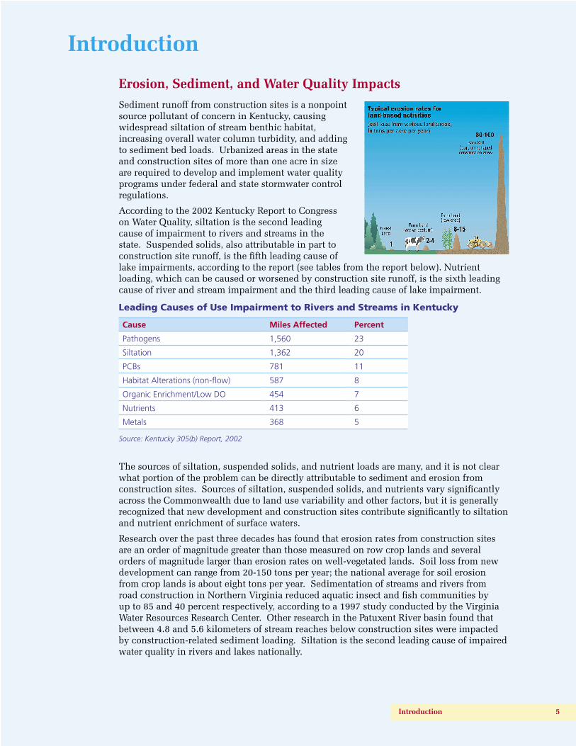
Sediment runoff from construction sites is a nonpoint source pollutant of concern in Kentucky, causing widespread siltation of stream benthic habitat, increasing overall water column turbidity, and adding to sediment bed loads. Urbanized areas in the state and construction sites of more than one acre in size are required to develop and implement water quality programs under federal and state stormwater control regulations.
According to the 2002 Kentucky Report to Congress on Water Quality, siltation is the second leading cause of impairment to rivers and streams in the state. Suspended solids, also attributable in part to construction site runoff, is the fifth leading cause of lake impairments, according to the report (see tables from the report below). Nutrient loading, which can be caused or worsened by construction site runoff, is the sixth leading cause of river and stream impairment and the third leading cause of lake impairment.
Leading Causes of Use Impairment to Rivers and Streams in Kentucky
Cause Miles Affected Percent
Pathogens 1,560 23
Siltation 1,362 20
PCBs 781 11
Habitat Alterations (non-flow) 587 8
Organic Enrichment/Low DO 454 7
Nutrients 413 6
Metals 368 5
Source: Kentucky 305(b) Report, 2002
The sources of siltation, suspended solids, and nutrient loads are many, and it is not clear what portion of the problem can be directly attributable to sediment and erosion from construction sites. Sources of siltation, suspended solids, and nutrients vary significantly across the Commonwealth due to land use variability and other factors, but it is generally recognized that new development and construction sites contribute significantly to siltation and nutrient enrichment of surface waters.
Research over the past three decades has found that erosion rates from construction sites are an order of magnitude greater than those measured on row crop lands and several orders of magnitude larger than erosion rates on well-vegetated lands. Soil loss from new development can range from 20-150 tons per year; the national average for soil erosion from crop lands is about eight tons per year. Sedimentation of streams and rivers from road construction in Northern Virginia reduced aquatic insect and fish communities by up to 85 and 40 percent respectively, according to a 1997 study conducted by the Virginia Water Resources Research Center. Other research in the Patuxent River basin found that between 4.8 and 5.6 kilometers of stream reaches below construction sites were impacted by construction-related sediment loading. Siltation is the second leading cause of impaired water quality in rivers and lakes nationally.
Introduction 5
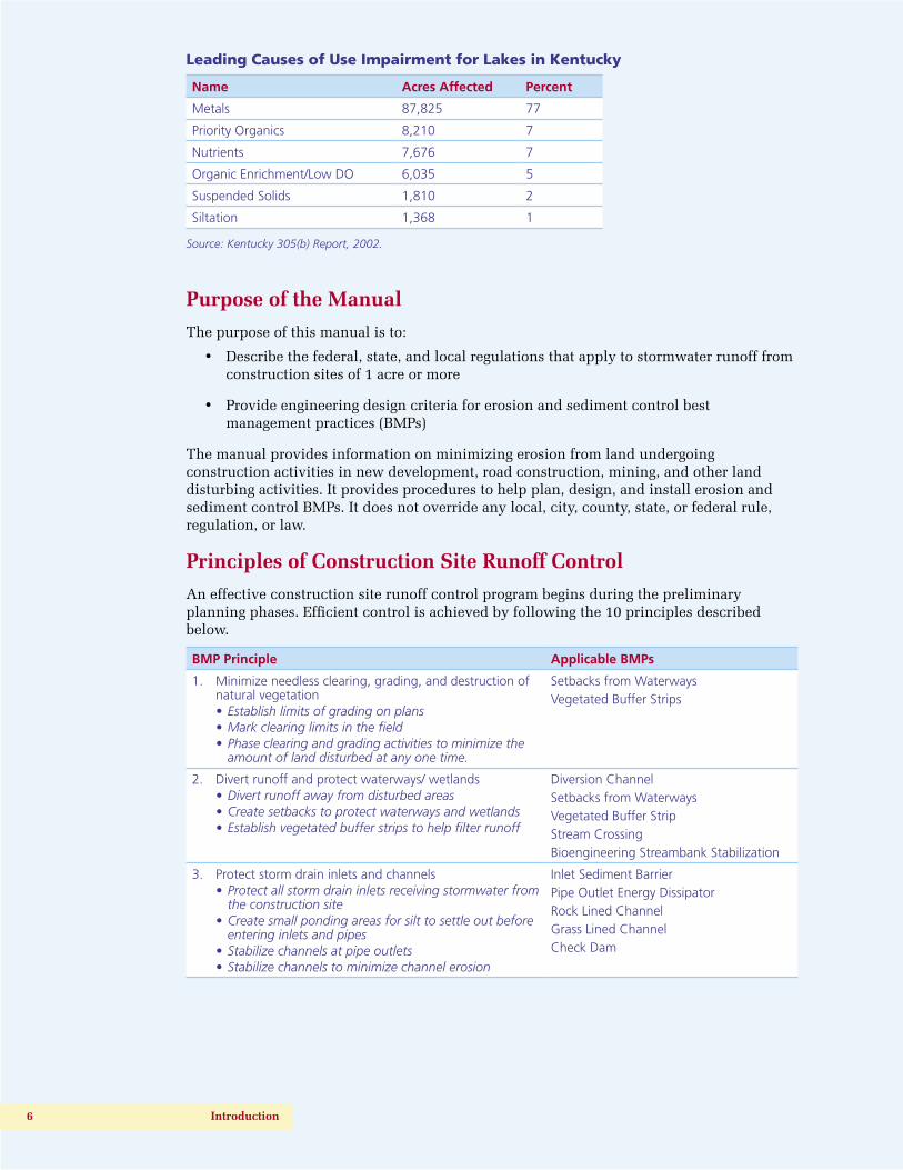
Leading Causes of Use Impairment for Lakes in Kentucky
Name Acres Affected Percent
Metals 87,825 77
Priority Organics 8,210 7
Nutrients 7,676 7
Organic Enrichment/Low DO 6,035 5
Suspended Solids 1,810 2
Siltation 1,368 1
Source: Kentucky 305(b) Report, 2002.
Purpose of the Manual
The purpose of this manual is to:
• Describe the federal, state, and local regulations that apply to stormwater runoff from construction sites of 1 acre or more
• Provide engineering design criteria for erosion and sediment control best management practices (BMPs)
The manual provides information on minimizing erosion from land undergoing construction activities in new development, road construction, mining, and other land disturbing activities. It provides procedures to help plan, design, and install erosion and sediment control BMPs. It does not override any local, city, county, state, or federal rule, regulation, or law.
Principles of Construction Site Runoff Control
An effective construction site runoff control program begins during the preliminary planning phases. Efficient control is achieved by following the 10 principles described below.
BMP Principle Applicable BMPs
1. Minimize needless clearing, grading, and destruction of natural vegetation• Establish limits of grading on plans• Mark clearing limits in the field• Phase clearing and grading activities to minimize the
amount of land disturbed at any one time.
Setbacks from WaterwaysVegetated Buffer Strips
2. Divert runoff and protect waterways/ wetlands• Divert runoff away from disturbed areas• Create setbacks to protect waterways and wetlands• Establish vegetated buffer strips to help filter runoff
Diversion ChannelSetbacks from WaterwaysVegetated Buffer StripStream CrossingBioengineering Streambank Stabilization
3. Protect storm drain inlets and channels• Protect all storm drain inlets receiving stormwater from
the construction site• Create small ponding areas for silt to settle out before
entering inlets and pipes• Stabilize channels at pipe outlets• Stabilize channels to minimize channel erosion
Inlet Sediment BarrierPipe Outlet Energy DissipatorRock Lined ChannelGrass Lined ChannelCheck Dam
6 Introduction

4. Protect slopes and disturbed areas• Cover bare soil with vegetation• Use erosion control blankets on steep slopes and in
channels to promote the growth of grass• Protect steep slopes from erosion
Seed, Mulch, and SodTopsoil Stockpiling, Dust Control Blankets and MatsSurface RougheningSlope Drain, GabionCellular Confinement SystemsPolyacrylamides
5. Establish stabilized construction entrances to minimize tracking of sediment
Construction Entrance
6. Install sediment barriers on contour and at site perimeter to filter sediments
Silt FenceBrush, Rock, and Commercial Sediment Barriers
7. Use dewatering practices when necessary Dewatering Structure
8. Control runoff using sediment traps or basins to remove settleable solids
Sediment Trap and Basin
9. Control waste and other pollutants• Provide cover for all chemicals, liquid products and
other materials that could contaminate runoff• Provide adequate trash receptacles and debris removal• Provide concrete truck washouts• Protect fueling and equipment repair areas from
stormwater runoff
Debris and Trash ManagementChemical ManagementConcrete Waste ManagementSanitary Facilities
10. Install, inspect, and maintain BMPs• Train construction site workers on the purpose of
BMPs, installation techniques, and maintenance requirements
• Install BMPs and implement the BMP plan• Inspect BMPs every 7 days and within 24 hours of
every rainfall 0.5 inches or greater• Maintain BMPs
Covered in the BMP Plan
Low Impact Design
Low Impact Design (LID) is a new approach to managing stormwater in new development that has been found to be cost effective for the developer while protecting the water quality of streams and lakes. Much has been written about LID, and more information can be found on EPA’s website at http://www.epa.gov/owow/nps/lid/.
The goal of LID in new development is to maintain the predevelopment hydrologic conditions. This is accomplished by controlling stormwater runoff near its source and using practices that promote infiltration and evaporation. The LID Site Planning Process is described below and was taken from Low Impact Development Design Strategies (1999):
1. Identify and protect riparian areas during construction, including floodplains, stream buffers, wetlands, woodlands, steep slopes, highly permeable soils, and highly erosive soils.
2. Minimize clearing and grading by:
• restricting grading to the smallest possible area
• locating development away from floodplains, steep slopes, and wetlands
• minimizing construction easements
• preserving existing trees
• minimizing impervious surfaces
• disconnecting impervious surfaces to increase infiltration
3. Use hydrology as a design element when considering the location of park and play areas, potential building sites, and drainage paths.
Introduction 7
4. Minimize total impervious area by considering
• roadway layouts that require less linear feet of streets
• narrow road sections
• sidewalks on only one side of the road
• reduced on street parking
• vertical construction of buildings to minimize roof area
• using shared driveways
• limiting driveway width to 9 feet
• reduced building setback to shorten driveway length
5. Minimize directly connected impervious areas by directing runoff from roof drains, driveway, and other paved surfaces to vegetated areas.
6. Maximize the hydrologic time of concentration by
• increasing overland sheet fl ow by letting the runoff spread out into grassy areas before reaching the stream
• increase the drainage fl ow path by directing runoff into bioretention and infi ltration areas before it leaves the lot
• lengthen and fl atten slopes on lots
• use vegetated swales instead of pipes
• increase vegetation on the site
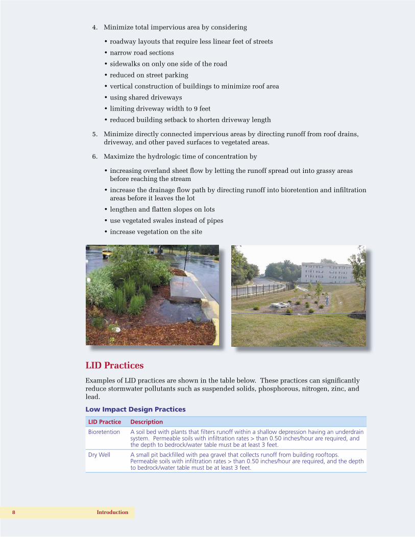
LID Practices
Examples of LID practices are shown in the table below. These practices can signifi cantly reduce stormwater pollutants such as suspended solids, phosphorous, nitrogen, zinc, and lead.
Low Impact Design Practices
LID Practice Description
Bioretention A soil bed with plants that fi lters runoff within a shallow depression having an underdrain system. Permeable soils with infi ltration rates > than 0.50 inches/hour are required, and the depth to bedrock/water table must be at least 3 feet.
Dry Well A small pit backfi lled with pea gravel that collects runoff from building rooftops. Permeable soils with infi ltration rates > than 0.50 inches/hour are required, and the depth to bedrock/water table must be at least 3 feet.
8 Introduction

Filter/Buffer Strips of grass planted between the stream and an impervious area such as a parking lot. The filter can control overland sheet flow only, with a maximum flow of 3.5 cubic feet per second. The size of the filter strip is based on the required treatment volume but should not exceed an overland flow length of 75’.
Grass Swale A grass open channel often used on highway projects to promote infiltration.
Infiltration Trench
An excavated trench backfilled with stone that collects runoff and holds it for several days as it infiltrates into the soil. Permeable soils with infiltration rates > than 0.50 inches/hour are required, and the depth to bedrock/water table must be at least 3 feet.
LID References
For more on Low Impact Development Design Strategies (1999), go to
http://www.epa.gov/owow/nps/lid/lidnatl.pdf
For a Builder’s guide to low impact development, go to
http://www.lowimpactdevelopment.org/lid%20articles/Builder_LID.pdf
For a Municipal Guide to low impact development, go to
http://www.lowimpactdevelopment.org/lid%20articles/Municipal_LID.pdf
References
• Tetra Tech, Inc., Kentucky Erosion Prevention and Sediment Control Field Guide, 2004
• Kentucky Division of Water and Division of Conservation, Best Management Practices for Construction Activities, 1994
• Kentucky Transportation Cabinet, Department of Highways, Standard Specifications for Road and Bridge Construction, 2004
• Salix Applied Earthcare, Erosion Draw 5.0 - Erosion Control Standards and Construction Drawings, 2004
• Lexington-Fayette Urban County Government, Stormwater Manual, Chapter 11, Erosion and Sediment Control, 2001
• Louisville and Jefferson County Metropolitan Sewer District, Design Manual, Chapter 12, Erosion Prevention and Sediment Control, 2001
• Tennessee Division of Water Pollution Control, Erosion and Sediment Control Handbook, 2002
• City of Knoxville, Engineering Division, Stormwater Engineering Section, Best Management Practices (BMP) Manual, May 2003
• Prince George’s County, Maryland, Department of Environmental Resources Programs and Planning, Division, Low-Impact Development Design Strategies, An Integrated Design Approach, June 1999
• Erosion Control Technology Council, Classifying Rolled Erosion Control Products: A Current Persepctive, 2003
Introduction 9
Regulations and Requirements
Federal and State Stormwater Permit Requirements
Federal Requirements
EPA regulations at 40 CFR 122.26(b)(14)(x) and 122.26(b)(15) require NPDES stormwater discharge permit coverage for discharges from construction activities that disturb one or more acres. These regulations are implemented by general NPDES permits, which are issued by EPA and authorized State agencies such as the Kentucky Division of Water.
The KPDES Construction General Permit was developed to satisfy federal stormwater permitting requirements. KPDES Construction General Permits meet all federal permit requirements and most of the requirements of local governments in Kentucky, though some local governments have additional requirements that must also be addressed by the applicant. See below for a summary of the KPDES Construction General Permit requirements.
KPDES Permit for Construction Activities
The KPDES Permit covers all stormwater discharges associated with construction activity that disturbs one acre or more. A copy of this permit can be downloaded from
http://www.water.ky.gov/permitting/wastewaterpermitting/KPDES/storm
The permit requires all construction activity in Kentucky disturbing one acre or more to:
• Submit a signed Notice of Intent (NOI) form to Kentucky Division of Water at least 48 hours before construction activity begins.
• Submit a copy of the NOI to the municipal operator of any municipal separate storm sewer system (MS4) into which the site discharges.
• Develop and implement a “Stormwater Pollution Prevention” plan.
• Continue to implement the plan during construction activity, including inspections every 7 days and after each rain of one-half inch or more.
• Submit a signed Notice of Termination (NOT) form to Kentucky Division of Water after the site has been finally stabilized.
The stormwater pollution prevention or “Best Management Practices” (BMP) plan must be developed in accordance with good engineering practices. The BMP plan must identify expected sources of pollution and describe how they will be controlled. The BMP plan must be completed prior to construction, signed, and kept onsite. BMP plans required by this permit are considered reports that shall be made available to the public, upon written request, in accordance with Section 308(b) of the Clean Water Act (CWA). Deficient plans may require modification upon notification by the KY Division of Water or local regulatory authority. The BMP plan must include, as a minimum, the following:
Site Description: The BMP plan shall include a clear description of the nature of the construction activity, the order of major soil disturbing activities, estimates of the total project area and the total disturbed area, the post construction runoff coefficient, any existing data describing soil condition or discharge quality, receiving water name, and a site map. The site map shall indicate drainage patterns and show approximate slopes after grading, areas of disturbance, the location of control measures, surface waters, wetlands, and stormwater discharge locations.
Sediment and Erosion Control Measures: The BMP plan must include a clear description of what sediment and erosion control measures will be used and when they will be implemented. The following control measures shall be used as a minimum:
• Soil Stabilization Practices – Existing vegetation shall be preserved where possible. All disturbed areas of the site shall be stabilized. Stabilization shall begin within 14 days on areas of the site where construction activities have permanently or temporarily (for 21 days or more) ceased. When snow cover causes delays, stabilization shall begin as soon as possible. Stabilization practices include seeding, mulching, placing sod, planting trees or shrubs, and using geotextile fabrics and other appropriate measures.
• Perimeter Structural Practices – Silt fences or other equivalent structural practices shall be used on all side and down slope borders of the site. Alternatively, a sediment basin shall be used that provides 3,600 cubic feet of storage capacity per disturbed acre drained. For common drainage locations that serve more than ten (10) disturbed acres at one time, a sediment basin must be used if possible. Structural practices include protecting drain inlets and outlets and using silt fences, earthen dikes, drainage swales, sediment traps, check dams, subsurface drains, pipe slope drains, reinforced soil retaining systems, gabions, sediment basins and other appropriate measures.
• Stormwater Management Devices – Management devices shall be installed during construction to control the pollutants in stormwater discharges that will occur after construction has been completed. Velocity dissipation devices shall be placed at discharge locations and along outfall channels as necessary to provide a non-erosive flow. The goal should be 80% removal of Total Suspended Solids that exceed predevelopment levels. If this goal is not met, the permitee shall provide justification for refusing each device based on site conditions.
Other Control Measures: No solid materials, including building materials, shall be discharged to waters of the Commonwealth, except as authorized by a Section 404 permit. Off-site vehicle sediment tracking and dust generation shall be minimized. Waste disposal methods and sanitary sewer or septic systems shall comply with applicable state or local regulations.
Other State or Local Plans: The BMP plan shall include any requirements specified in sediment and erosion control plans, stormwater management plans or permits that have been approved by other state or local officials.
Maintenance: The BMP plan shall include a clear description of the maintenance procedures necessary to keep the control measures in good and effective operating condition.
Inspections: Qualified personnel shall inspect all stormwater control measures and drainage features at least once every seven days and within 24 hours of the end of a rainfall that is 0.5 inches or greater. Discharge locations shall be inspected to ensure that velocity dissipaters prevent significant impacts to receiving waters. Vehicle exits shall be inspected for evidence of offsite sediment tracking. Disturbed areas and material storage areas that are exposed to precipitation shall be inspected for evidence of pollutants entering the drainage system. A signed report summarizing the scope of the inspection, major observations, and any corrective actions taken shall be made and kept as part of the BMP plan.
Non-Stormwater Discharges: The BMP plan shall identify and ensure the implementation of appropriate pollution prevention measures for any non-stormwater component of a discharge as listed in PART III C of the permit, except for flows from fire fighting activities.
Contractors and Subcontractors: The BMP plan shall clearly state the contractor or subcontractors that will implement each control measure identified in the BMP plan. All contractors and subcontractors identified in the BMP plan must sign a copy of the certification statement below before conducting any professional service at the site:
“I certify under penalty of law that I understand the terms and conditions of the general National Pollutant Discharge Elimination System (NPDES) permit that authorizes the stormwater discharges associated with industrial activity from the construction site identified as part of this certification.”
The certification must include the name and title of the person providing the signature, the name, address, and telephone number of the contracted firm, the address, or other identifying description of the site and the date the certification is made. All certification statements must be included in the BMP plan.
ESC Plan Requirements for Local Governments in Kentucky
Some urban areas in Kentucky have specific requirements for filing earth disturbance plans prior to construction. Check with each local government prior to construction in urban areas to make sure your understanding of the permit requirements is up-to-date. Below is a summary of the requirements of the Metropolitan Sewer District of Louisville and Jefferson County, the Lexington-Fayette Urban County Government, and Sanitation District #1 in Northern Kentucky.
Louisville – Jefferson County Metropolitan Sewer District
On November 21, 2000, the Jefferson County Fiscal Court adopted an Erosion Prevention and Sediment Control (EPSC) Ordinance that applies to all land disturbing activities in Jefferson County, including single family, commercial, residential, and utility construction. Activities disturbing 5,000 sq ft or less and not requiring a building permit, limited private development site investigations, and surveying prior to plan application are exempt.
The EPSC Ordinance requires that all EPSC measures be designed and installed to accomplish an 80% design removal efficiency goal for total suspended solids. The MSD Design Manual, Standard Drawings, and Standard Specifications contain approved structural and non-structural Best Management Practices (BMPs) for use in achieving this standard. Structural BMPs include sediment trapping devices, inlet protection measures, perimeter controls, and construction entrances. Non-structural methods include phasing a project into manageable pieces, scheduling activities within each phase to minimize amount of disturbed area and provisions for temporary and final stabilization.
The Permitee, or his or her designee, is required to conduct inspections of all EPSC measures and perform any modifications, maintenance, or repairs as necessary, every seven calendar days and within 24 hours of each storm event that produces 0.5 inches or more of precipitation. Records of these inspections must be kept on site at all times for review by the appropriate compliance enforcement agency.
For more information, visit the MSD web site at http://www.msdlouky.org/insidemsd/epsc.htm
Lexington-Fayette Urban County Government
An erosion and sediment control plan must be approved by the LFUCG before construction commences for any disturbed area other than the construction of a single family, two family, or townhouse residence. The plan shall be developed and signed by a professional engineer or landscape architect licensed in Kentucky. All hydrologic, hydraulic, structural, and geotechnical design work included in the plan must be done and signed by a professional engineer licensed in Kentucky. Plans must integrate nonstructural and structural practices and procedures to control erosion and sediment loss. Once the erosion and sediment control practices have been constructed, a grading permit can be obtained. The erosion control plan remains in effect throughout the construction project, including the homebuilding phase of construction for residential subdivisions.
An operation and maintenance plan must be developed which provides a schedule for inspection, maintenance, and repair of BMPs during construction activities. A maintenance schedule shall also be provided to ensure that permanent measures such as vegetation are properly established after construction is complete. All erosion and sediment controls that are identified in the ESCP shall be inspected and maintained. Any erosion and sediment control devices that are damaged shall be repaired or replaced immediately.
Land disturbances for the construction of a structure on a single residential lot are permitted through the building permit process and must comply with LFUCG
requirements. For more information, see http://www.lfucg.com/Engineering/, and the stormwater manual at http://www.lfucg.com/engineering/engmansw.asp.
Sanitation District # 1 in Northern Kentucky
Sanitation District # 1 (SD1) serves 33 communities in Boone, Campbell, and Kenton Counties of Northern Kentucky. SD1 has established a “Land Disturbance Permit” to control stormwater runoff from construction sites and post-construction stormwater management for new developments and re-developments in Boone, Campbell, and Kenton Counties and the municipalities in those counties in the area covered by the KPDES SMS4 Stormwater Permit with the exception of the city of Florence.
The regulations require the implementation of proper erosion and sediment control practices; controls for other wastes; and the implementation of post-construction runoff controls in areas undergoing development or re-development. These regulations require review of improvement plans for new developments and re-developments; site inspections and enforcement activities of control measures; long-term operation and maintenance of post-construction controls; and sanctions to ensure compliance. The requirements apply to all land disturbing activities and all development or re-development activities that disturb an area greater than or equal to one acre. Sites that are smaller than one (1) acre may also be covered by these regulations if they are a part of a larger common plan of development or sale.
Persons responsible for a land disturbing activity, development activity, or redevelopment activity shall make application to the District. The land disturbing activity, development activity, or re-development activity cannot commence until the District has issued a Land Disturbance Permit. Drawings of the site with information on drainage, erosion, and sediment controls to be used, and other details are also required. For more information, see http://www.sd1.org/StormWater/SWRules&Regs.html.
Other Phase II Stormwater Cities
Cities in Kentucky with more than 10,000 population (e.g., Bowling Green, Henderson, Madisonville, Elizabethtown, Winchester, Richmond, Georgetown, Somerset, etc.) are subject to KPDES permits under the Kentucky Phase II Stormwater Program. Regulations are similar to those of larger cities—all construction sites of one acre or more must have written erosion and sediment control plans, controls must be inspected every seven days or after rains of one-half inch or more, controls must be removed after the site is stabilized, etc. For more information on the permit process, see http://www.water.ky.gov/permitting/wastewaterpermitting/KPDES/storm/.
For regulatory information, see
http://www.lrc.state.ky.us/kar/401/005/002.htm.
Kentucky Transportation Cabinet (KYTC)
The KYTC specific requirements for their projects are listed below:
• Inspection and documentation of all controls must occur weekly and after each rain of 0.1 inch or more.
• Approved curled wood fiber or straw/coconut fiber erosion control blankets or mats must be used in all ditches (except sodded, paved, and channel-lined ditches) and on all slopes of 4:1 or steeper, if upland drainage flow length exceeds 100 feet.
• Hydromulch in lieu of straw is acceptable during March 1 - May 15 and September 1 - November 1 only.
• Sufficient quantities of mulch and tackifier must be used to promote germination and control erosion until vegetation is established.
Projects conducted within the jurisdiction of a “Stormwater Phase II City” should coordinate activities with local stormwater programs.
KYTC requires an erosion control plan prior to excavation or grading. Erosion control plans require site drawings that show natural and constructed drainage features and the actions that will be taken to control both erosion on bare soil areas and sediment in sheet runoff or concentrated flows. Erosion and sediment control actions must be indicated on the site drawing. Natural streams and other surface waters should also be noted. Plans must indicate temporary and permanent erosion control features. At a minimum, this includes silt checks, silt traps, sediment traps/basins, silt fences, and other methods. Streams, wetlands, and other surface waters should be disturbed only when necessary, and as little as possible. Temporary stream crossings should be designated.
Erosion and sediment controls must be properly maintained during construction and closed out after construction to ensure continuing compliance with the permit and KYTC requirements. Specific design and other requirements can be found in the project contract documents.
Related Regulations
Federal 404 Permit
Section 404 of the Clean Water Act regulates the placement of dredged or fill material into the waters of the U.S., including small streams and wetlands adjacent or connected to regulated waters. The U.S. Army Corps of Engineers (USACE) administers the permit program dealing with these activities, in cooperation with the U.S. Environmental Protection Agency (USEPA) and in consultation with the U.S. Forest Service and the National Marine Fisheries Service. Individual Permits are issued for activities with significant impacts, and Nationwide or regional general permits are issued for activities with impacts not deemed to be significant.
For minor activities covered under Section 404 Nationwide Permits (e.g., road culvert installation, utility line activities, bank stabilization, etc.), permit requirements are typically deemed to be met if activities result in only short-term, limited effects and if all appropriate and reasonable measures related to erosion and sediment control, project seeding and stabilization, and prevention of water quality degradation (e.g., working during low-flow conditions) are applied and maintained. Applicants will be responsible for ensuring that erosion and sediment control measures are selected, installed, and maintained properly.
The Nationwide Permits allow certain types of construction in streams and wetlands without getting formal approval from the Corps of Engineers. However, in many cases you must notify the Corps in writing at least 30 days before you begin construction. Common activities covered by a Nationwide Permit are shown below. If the construction is not covered by a Nationwide Permit, then an Individual Permit must be obtained from the Corps of Engineers before beginning work.
For more information, go to http://www.usace.army.mil/inet/functions/cw/cecwo/reg/oceover.htm
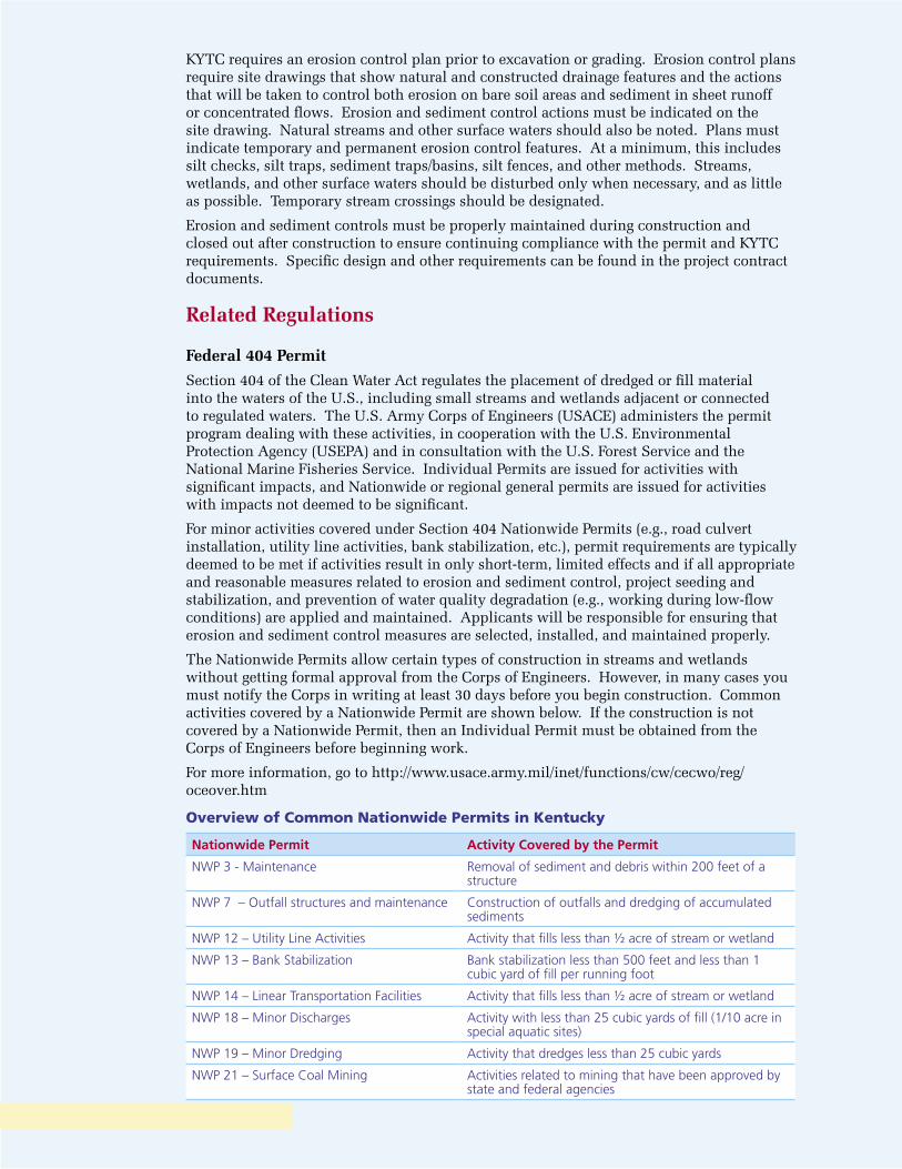
Overview of Common Nationwide Permits in Kentucky
Nationwide Permit Activity Covered by the Permit
NWP 3 - Maintenance Removal of sediment and debris within 200 feet of a structure
NWP 7 – Outfall structures and maintenance Construction of outfalls and dredging of accumulated sediments
NWP 12 – Utility Line Activities Activity that fills less than ½ acre of stream or wetland
NWP 13 – Bank Stabilization Bank stabilization less than 500 feet and less than 1 cubic yard of fill per running foot
NWP 14 – Linear Transportation Facilities Activity that fills less than ½ acre of stream or wetland
NWP 18 – Minor Discharges Activity with less than 25 cubic yards of fill (1/10 acre in special aquatic sites)
NWP 19 – Minor Dredging Activity that dredges less than 25 cubic yards
NWP 21 – Surface Coal Mining Activities related to mining that have been approved by state and federal agencies
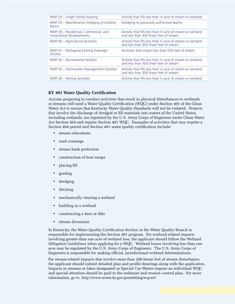
NWP 29 – Single Family Housing Activity that fills less than ¼ acre of stream or wetland
NWP 35 – Maintenance Dredging of Existing Basins
Dredging to previously authorized depths
NWP 39 – Residential, Commercial, and Institutional Developments
Activity that fills less than ½ acre of stream or wetland and less than 300 linear feet of stream
NWP 40 – Agricultural Activities Activity that fills less than ½ acre of stream or wetland and less than 300 linear feet of stream
NWP 41 – Reshaping Existing Drainage Ditches
Activities that impact less than 500 feet of stream
NWP 42 – Recreational Facilities Activity that fills less than ½ acre of stream or wetland and less than 300 linear feet of stream
NWP 43 – Stormwater Management Facilities Activity that fills less than ½ acre of stream or wetland and less than 300 linear feet of stream
NWP 44 – Mining Activities Activity that fills less than ½ acre of stream or wetland
KY 401 Water Quality Certification
Anyone proposing to conduct activities that result in physical disturbances to wetlands or streams will need a Water Quality Certification (WQC) under Section 401 of the Clean Water Act to ensure that Kentucky Water Quality Standards will not be violated. Projects that involve the discharge of dredged or fill materials into waters of the United States, including wetlands, are regulated by the U.S. Army Corps of Engineers under Clean Water Act Section 404 and require Section 401 WQC. Examples of activities that may require a Section 404 permit and Section 401 water quality certification include:
• stream relocations
• road crossings
• stream bank protection
• construction of boat ramps
• placing fill
• grading
• dredging
• ditching
• mechanically clearing a wetland
• building in a wetland
• constructing a dam or dike
• stream diversions
In Kentucky, the Water Quality Certification Section in the Water Quality Branch is responsible for implementing the Section 401 program. For wetland-related impacts involving greater than one acre of wetland loss, the applicant should follow the Wetland Mitigation Guidelines when applying for a WQC. Wetland losses involving less than one acre may be regulated by the U.S. Army Corps of Engineers. The U.S. Army Corps of Engineers is responsible for making official, jurisdictional wetland determinations.
For stream-related impacts that involve more than 200 linear feet of stream disturbance, the applicant should submit detailed plan and profile drawings along with the application. Impacts in streams or lakes designated as Special Use Waters require an individual WQC and special attention should be paid to the sediment and erosion control plan. For more information, go to http://www.water.ky.gov/permitting/wqcert/
KY Floodplain Construction Permit
The Kentucky Division of Water Floodplain Management Section has the primary responsibility for the approval or denial of proposed construction and other activities in the 100-year floodplain of all streams in the Commonwealth. Typical activities permitted are dams, bridges, culverts, residential and commercial buildings, placement of fill, stream alterations or relocations, small impoundments, and water and wastewater treatment plants.
Applicants must submit a completed application with a location map, plans of the proposed construction, and the addressing of public notice. If the proposed construction lies in an area where there is no existing floodplain information, hydrologic and hydraulic analysis must be performed. KDOW engineers will perform the required analysis provided the Applicant supplies them with the floodplain geometry in the form of cross sections, preferably tabulated on an Excel Spreadsheet. This analysis determines the effects the proposed construction has on existing flood conditions and determines the expected 100-year flood heights and the delineation of the floodway (a portion of the natural floodplain that is restricted to little or no construction). From this analysis, construction limits for fills and buildings and required elevations for finished floors or floodproofing can be provided. For all construction, especially bridges and culverts, a check is made to ensure that the project has only minimal impacts on existing flood levels. Regulations limit the effect to a maximum of one foot.
For more information, see http://water.ky.gov/permitting/floodconstr/.
Stormwater Best Management Practices Plan
BMP Plan Requirements
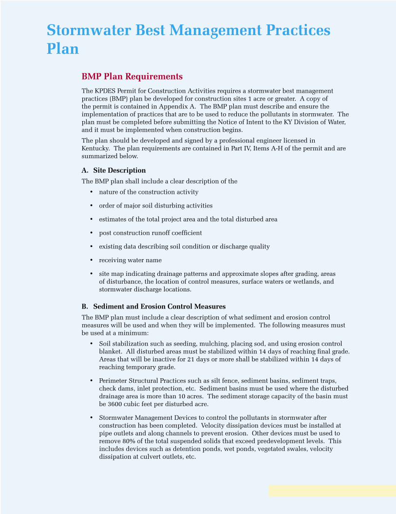
The KPDES Permit for Construction Activities requires a stormwater best management practices (BMP) plan be developed for construction sites 1 acre or greater. A copy of the permit is contained in Appendix A. The BMP plan must describe and ensure the implementation of practices that are to be used to reduce the pollutants in stormwater. The plan must be completed before submitting the Notice of Intent to the KY Division of Water, and it must be implemented when construction begins.
The plan should be developed and signed by a professional engineer licensed in Kentucky. The plan requirements are contained in Part IV, Items A-H of the permit and are summarized below.
A. Site Description
The BMP plan shall include a clear description of the
• nature of the construction activity
• order of major soil disturbing activities
• estimates of the total project area and the total disturbed area
• post construction runoff coefficient
• existing data describing soil condition or discharge quality
• receiving water name
• site map indicating drainage patterns and approximate slopes after grading, areas of disturbance, the location of control measures, surface waters or wetlands, and stormwater discharge locations.
B. Sediment and Erosion Control Measures
The BMP plan must include a clear description of what sediment and erosion control measures will be used and when they will be implemented. The following measures must be used at a minimum:
• Soil stabilization such as seeding, mulching, placing sod, and using erosion control blanket. All disturbed areas must be stabilized within 14 days of reaching final grade. Areas that will be inactive for 21 days or more shall be stabilized within 14 days of reaching temporary grade.
• Perimeter Structural Practices such as silt fence, sediment basins, sediment traps, check dams, inlet protection, etc. Sediment basins must be used where the disturbed drainage area is more than 10 acres. The sediment storage capacity of the basin must be 3600 cubic feet per disturbed acre.
• Stormwater Management Devices to control the pollutants in stormwater after construction has been completed. Velocity dissipation devices must be installed at pipe outlets and along channels to prevent erosion. Other devices must be used to remove 80% of the total suspended solids that exceed predevelopment levels. This includes devices such as detention ponds, wet ponds, vegetated swales, velocity dissipation at culvert outlets, etc.
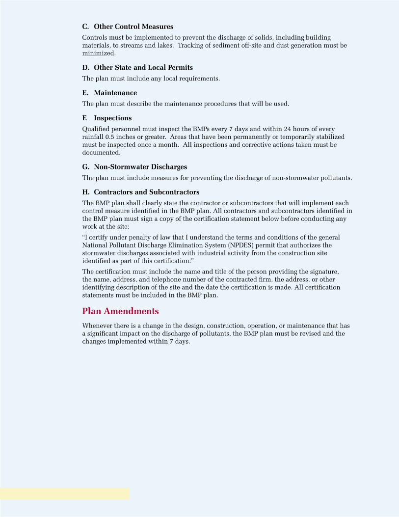
C. Other Control Measures
Controls must be implemented to prevent the discharge of solids, including building materials, to streams and lakes. Tracking of sediment off-site and dust generation must be minimized.
D. Other State and Local Permits
The plan must include any local requirements.
E. Maintenance
The plan must describe the maintenance procedures that will be used.
F. Inspections
Qualified personnel must inspect the BMPs every 7 days and within 24 hours of every rainfall 0.5 inches or greater. Areas that have been permanently or temporarily stabilized must be inspected once a month. All inspections and corrective actions taken must be documented.
G. Non-Stormwater Discharges
The plan must include measures for preventing the discharge of non-stormwater pollutants.
H. Contractors and Subcontractors
The BMP plan shall clearly state the contractor or subcontractors that will implement each control measure identified in the BMP plan. All contractors and subcontractors identified in the BMP plan must sign a copy of the certification statement below before conducting any work at the site:
“I certify under penalty of law that I understand the terms and conditions of the general National Pollutant Discharge Elimination System (NPDES) permit that authorizes the stormwater discharges associated with industrial activity from the construction site identified as part of this certification.”
The certification must include the name and title of the person providing the signature, the name, address, and telephone number of the contracted firm, the address, or other identifying description of the site and the date the certification is made. All certification statements must be included in the BMP plan.
Plan Amendments
Whenever there is a change in the design, construction, operation, or maintenance that has a significant impact on the discharge of pollutants, the BMP plan must be revised and the changes implemented within 7 days.
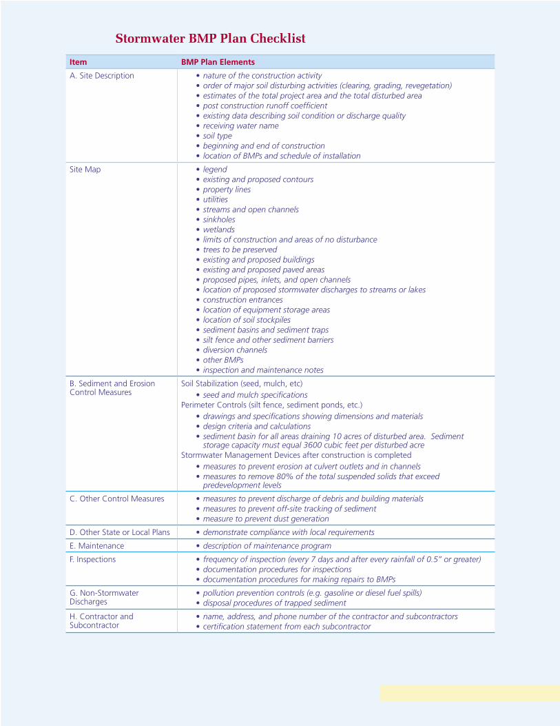
Stormwater BMP Plan Checklist
Item BMP Plan Elements
A. Site Description • nature of the construction activity• order of major soil disturbing activities (clearing, grading, revegetation)• estimates of the total project area and the total disturbed area• post construction runoff coefficient• existing data describing soil condition or discharge quality• receiving water name• soil type• beginning and end of construction• location of BMPs and schedule of installation
Site Map • legend• existing and proposed contours• property lines• utilities• streams and open channels• sinkholes• wetlands• limits of construction and areas of no disturbance• trees to be preserved• existing and proposed buildings• existing and proposed paved areas• proposed pipes, inlets, and open channels• location of proposed stormwater discharges to streams or lakes • construction entrances• location of equipment storage areas• location of soil stockpiles• sediment basins and sediment traps• silt fence and other sediment barriers • diversion channels• other BMPs• inspection and maintenance notes
B. Sediment and Erosion Control Measures
Soil Stabilization (seed, mulch, etc)• seed and mulch specifications
Perimeter Controls (silt fence, sediment ponds, etc.)• drawings and specifications showing dimensions and materials • design criteria and calculations• sediment basin for all areas draining 10 acres of disturbed area. Sediment
storage capacity must equal 3600 cubic feet per disturbed acre Stormwater Management Devices after construction is completed
• measures to prevent erosion at culvert outlets and in channels• measures to remove 80% of the total suspended solids that exceed
predevelopment levels
C. Other Control Measures • measures to prevent discharge of debris and building materials• measures to prevent off-site tracking of sediment• measure to prevent dust generation
D. Other State or Local Plans • demonstrate compliance with local requirements
E. Maintenance • description of maintenance program
F. Inspections • frequency of inspection (every 7 days and after every rainfall of 0.5” or greater)• documentation procedures for inspections• documentation procedures for making repairs to BMPs
G. Non-Stormwater Discharges
• pollution prevention controls (e.g. gasoline or diesel fuel spills)• disposal procedures of trapped sediment
H. Contractor and Subcontractor
• name, address, and phone number of the contractor and subcontractors• certification statement from each subcontractor
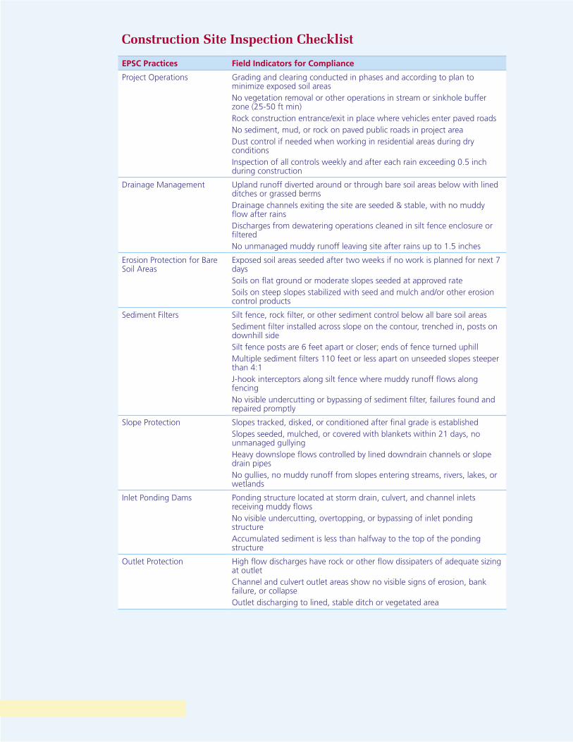
Construction Site Inspection Checklist
EPSC Practices Field Indicators for Compliance
Project Operations Grading and clearing conducted in phases and according to plan to minimize exposed soil areasNo vegetation removal or other operations in stream or sinkhole buffer zone (25-50 ft min)Rock construction entrance/exit in place where vehicles enter paved roadsNo sediment, mud, or rock on paved public roads in project areaDust control if needed when working in residential areas during dry conditionsInspection of all controls weekly and after each rain exceeding 0.5 inch during construction
Drainage Management Upland runoff diverted around or through bare soil areas below with lined ditches or grassed bermsDrainage channels exiting the site are seeded & stable, with no muddy flow after rainsDischarges from dewatering operations cleaned in silt fence enclosure or filteredNo unmanaged muddy runoff leaving site after rains up to 1.5 inches
Erosion Protection for Bare Soil Areas
Exposed soil areas seeded after two weeks if no work is planned for next 7 daysSoils on flat ground or moderate slopes seeded at approved rateSoils on steep slopes stabilized with seed and mulch and/or other erosion control products
Sediment Filters Silt fence, rock filter, or other sediment control below all bare soil areasSediment filter installed across slope on the contour, trenched in, posts on downhill sideSilt fence posts are 6 feet apart or closer; ends of fence turned uphillMultiple sediment filters 110 feet or less apart on unseeded slopes steeper than 4:1J-hook interceptors along silt fence where muddy runoff flows along fencingNo visible undercutting or bypassing of sediment filter, failures found and repaired promptly
Slope Protection Slopes tracked, disked, or conditioned after final grade is establishedSlopes seeded, mulched, or covered with blankets within 21 days, no unmanaged gullyingHeavy downslope flows controlled by lined downdrain channels or slope drain pipesNo gullies, no muddy runoff from slopes entering streams, rivers, lakes, or wetlands
Inlet Ponding Dams Ponding structure located at storm drain, culvert, and channel inlets receiving muddy flowsNo visible undercutting, overtopping, or bypassing of inlet ponding structureAccumulated sediment is less than halfway to the top of the ponding structure
Outlet Protection High flow discharges have rock or other flow dissipaters of adequate sizing at outletChannel and culvert outlet areas show no visible signs of erosion, bank failure, or collapseOutlet discharging to lined, stable ditch or vegetated area
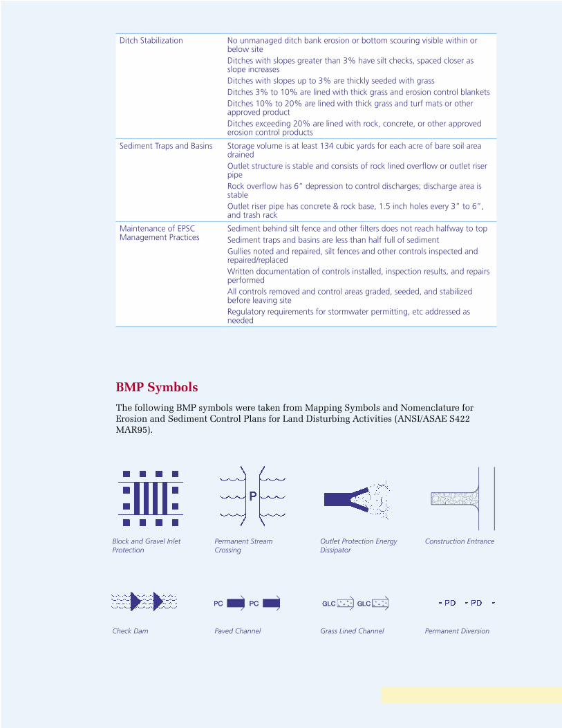
Ditch Stabilization No unmanaged ditch bank erosion or bottom scouring visible within or below siteDitches with slopes greater than 3% have silt checks, spaced closer as slope increasesDitches with slopes up to 3% are thickly seeded with grassDitches 3% to 10% are lined with thick grass and erosion control blanketsDitches 10% to 20% are lined with thick grass and turf mats or other approved productDitches exceeding 20% are lined with rock, concrete, or other approved erosion control products
Sediment Traps and Basins Storage volume is at least 134 cubic yards for each acre of bare soil area drainedOutlet structure is stable and consists of rock lined overflow or outlet riser pipeRock overflow has 6” depression to control discharges; discharge area is stableOutlet riser pipe has concrete & rock base, 1.5 inch holes every 3” to 6”, and trash rack
Maintenance of EPSC Management Practices
Sediment behind silt fence and other filters does not reach halfway to topSediment traps and basins are less than half full of sedimentGullies noted and repaired, silt fences and other controls inspected and repaired/replacedWritten documentation of controls installed, inspection results, and repairs performedAll controls removed and control areas graded, seeded, and stabilized before leaving siteRegulatory requirements for stormwater permitting, etc addressed as needed
BMP Symbols
The following BMP symbols were taken from Mapping Symbols and Nomenclature for Erosion and Sediment Control Plans for Land Disturbing Activities (ANSI/ASAE S422 MAR95).
Block and Gravel Inlet Protection
Permanent Stream Crossing
Outlet Protection Energy Dissipator
Construction Entrance
Check Dam Paved Channel Grass Lined Channel Permanent Diversion
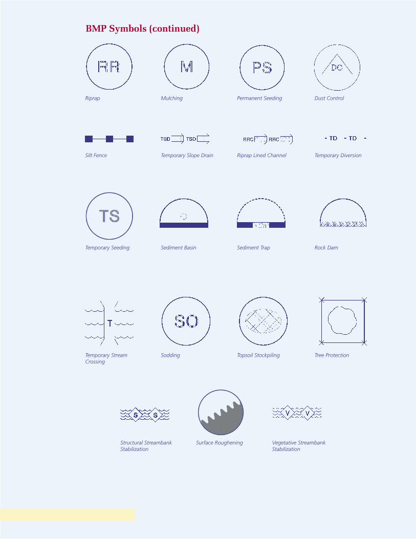
BMP Symbols (continued)
Riprap Mulching Permanent Seeding Dust Control
Silt Fence Temporary Slope Drain Riprap Lined Channel Temporary Diversion
Temporary Seeding Sediment Basin Sediment Trap Rock Dam
Temporary Stream Crossing
Sodding Topsoil Stockpiling Tree Protection
Structural Streambank Stabilization
Surface Roughening Vegetative Streambank Stabilization

Best Management Practices
BMP Selection Guidelines
Guidelines for selecting BMPs for construction sites are contained in the tables on the following pages. Each BMP is listed along with its purpose and application, relative effectiveness, and relative cost of installation and maintenance. The reader is also encouraged to review the KY Erosion Prevention and Sediment Control Field Guide.
The guide describes the erosion and sediment control process, beginning with sections on pre-project planning and operational activities. The rest of the guide discusses erosion prevention and sediment control by starting at the top of the hill, above the project site, and proceeding down the slope through the bare soil area, ditches and channels, traps and basins, and on down to the waterways below.
For state highway projects, the KY Transportation Cabinet Specifi cations for Road and Bridge Construction should be consulted. Sections 212, 213, and 214 address erosion control, water pollution control, and geotextile construction, respectively.
Forestry operations should consult the KY Forest Practice Guidelines for Water Quality Management, the complete handbook of the Best Management Practices required under the Forest Conservation Act.
Construction Site BMP Guidelines
BMP Purpose and Application Relative Effectiveness
Relative Installation and Maintenance Cost
Construction Entrance To keep sediment from being tracked onto public streets. A rock driveway of No. 2 stone is constructed where traffi c leaves the site.
High Moderate
Diversion Channel To prevent clean stormwater from fl owing through the disturbed area. Clean water from upslope areas is diverted around the site.
High Low
Temporary Seeding Provide temporary vegetation and reduce erosion. Must be applied within 14 days to areas where work has temporarily stopped for 21 days or more.
High Low
Permanent Seeding Provide permanent vegetation and reduce erosion. Must be applied within 14 days to areas that have reached fi nal grade.
High Low
Mulching Reduce erosion, foster the growth of grass, and keep the soil moist.
High Low
Sodding Quickly establish vegetation. High High
Topsoil Stockpiling Preserve topsoil for later use when seeding.
High Low

BMP Purpose and Application Relative Effectiveness
Relative Installation and Maintenance Cost
Dust Control Minimize dust on a construction site.
Low Low
Silt Fence Provide a place for water to pond and silt to fall out.
Moderate Moderate
Brush, Rock, and Commercial Barriers
Same as silt fence. Moderate Moderate
Erosion Control Blankets and Mats
Prevent erosion, promote the growth of grass by holding the seed in place, and keep the soil moist. Required for slopes greater than 3:1 and channel velocities greater than 5 feet per second.
High High
Surface Roughening Slow the velocity of water flowing down a slope and keep the seed and mulch in place. A dozer is operated up and down the slope to create small depressions with the tracks.
Moderate Low
Slope Drain Transport water down the face of a slope without causing erosion. A pipe or concrete lined channel may be used.
Moderate High
Gabion Stabilize steep slopes at the inlet or outlet of a pipe or in a stream bank. Should only be used if vegetation or erosion control blankets/mats will not work.
High High
Cellular Confinement Systems
Stabilize steep slopes. Should only be used if vegetation or erosion control blanket/mats will not work.
High High
Polyacrylamides Reduce soil erosion by spraying the chemical on soil, or adding it to sediment basins to increase the settling of soil particles.
Low High
Curb Inlet Sediment Barrier
Create a small ponding area for the silt to settle out at the front of the inlet using rock bags or similar products.
Low High
Drop Inlet Sediment Barrier
Create a small ponding area for the silt to settle out around the perimeter of the drop inlet using rock or silt fence.
Low High
Culvert Inlet Sediment Barrier
Create a small ponding area for the silt to settle out at the culvert entrance using rock.
Low High
Pipe Outlet Energy Dissipator
Reduce the velocity of water exiting a pipe using a rock apron.
Low High
Rock Lined Channel Prevent channel erosion using rock.
High High
Grass-Lined Channel Prevent channel erosion using vegetation.
High High
Check Dam Reduce the channel velocity and trap sediment
Low High
Sediment Trap Trap sediment by collecting it in a small depression and slowly discharging it.
Low Moderate
Construction Site BMP Guidelines (continued)
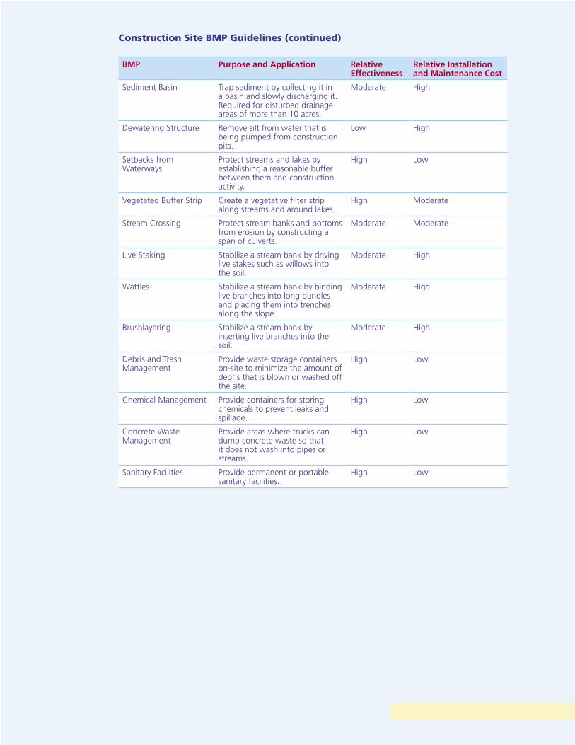
BMP Purpose and Application Relative Effectiveness
Relative Installation and Maintenance Cost
Sediment Basin Trap sediment by collecting it in a basin and slowly discharging it. Required for disturbed drainage areas of more than 10 acres.
Moderate High
Dewatering Structure Remove silt from water that is being pumped from construction pits.
Low High
Setbacks from Waterways
Protect streams and lakes by establishing a reasonable buffer between them and construction activity.
High Low
Vegetated Buffer Strip Create a vegetative filter strip along streams and around lakes.
High Moderate
Stream Crossing Protect stream banks and bottoms from erosion by constructing a span of culverts.
Moderate Moderate
Live Staking Stabilize a stream bank by driving live stakes such as willows into the soil.
Moderate High
Wattles Stabilize a stream bank by binding live branches into long bundles and placing them into trenches along the slope.
Moderate High
Brushlayering Stabilize a stream bank by inserting live branches into the soil.
Moderate High
Debris and Trash Management
Provide waste storage containers on-site to minimize the amount of debris that is blown or washed off the site.
High Low
Chemical Management Provide containers for storing chemicals to prevent leaks and spillage.
High Low
Concrete Waste Management
Provide areas where trucks can dump concrete waste so that it does not wash into pipes or streams.
High Low
Sanitary Facilities Provide permanent or portable sanitary facilities.
High Low
Construction Site BMP Guidelines (continued)

Construction Entrance
Defi nitionA temporary gravel construction entrance is a stabilized pad of crushed stone located at any point where traffi c enters or leaves a construction site onto a public right-of-way, street, alley, sidewalk, or parking area.
PurposeA stabilized construction entrance is intended to reduce off-site sedimentation by eliminating the tracking or fl owing of sediment onto public rights-of-way.
Design CriteriaConstruction plans shall limit traffi c to properly constructed and stabilized entrances. The entrance shall be located to minimize the impact to streams and storm drains.
Construction Specifi cations • The aggregate size for construction of the pad should be #2 (4 to 8 inch) rock
– not 57’s, 410 “traffi c bound” or DGA. Place the gravel to the specifi c grade and dimensions shown on the plans, and smooth it.
• The thickness of the pad shall not be less than 6 inches. Use geotextile fabrics to improve stability of the foundation.
• The width of the pad shall not be less than the full width of all points of ingress or egress and in any case shall not be less than 20 feet wide.
• The length of the pad shall be as required, but not less than 50 feet.
• Locate construction entrances and exits to limit sediment leaving the site and to provide for maximum utility by all construction vehicles. Avoid entrances that have steep grades and entrances at curves in public roads.
• Limit egress to designated exit by installing perimeter fencing.
26 Construction Entrance
Construction Entrance 27
• The entrance shall be maintained in a condition that will prevent tracking or flowing of sediment onto public rights-of-way. This may require periodic top dressing with additional stone as conditions demand, and repair and/or maintenance of any measures used to trap sediment.
• All sediment spilled, dropped, washed or tracked onto public rights-of-way shall be removed immediately.
• Provide drainage to carry water to a sediment trap or other suitable outlet.
• When necessary, wheels shall be cleaned to remove sediment prior to entrance onto public rights-of-way. When washing is required, it shall be done on an area stabilized with crushed stone that drains into an approved sediment trap or sediment basin.
• All sediment shall be prevented from entering any storm drain, ditch or watercourse through use of sand bags, gravel, or other approved methods.
Inspection and Maintenance • Maintain the gravel pad in a condition to prevent mud or sediment from leaving the
construction site. Add stones when required.
• Replace gravel material when surface voids are visible.
• Inspect any structure used to trap sediment and clean it out as necessary.
• Immediately remove all objectionable materials spilled, washed, or tracked onto public roadways. Remove all sediment deposited on paved roadways within 24 hours.
• Check that exit is used exclusively by all traffic.
• Inspect weekly and after each rainfall.
• Stir aggregate with backhoe on a weekly basis or as required based on construction activity.
Diversion Channel
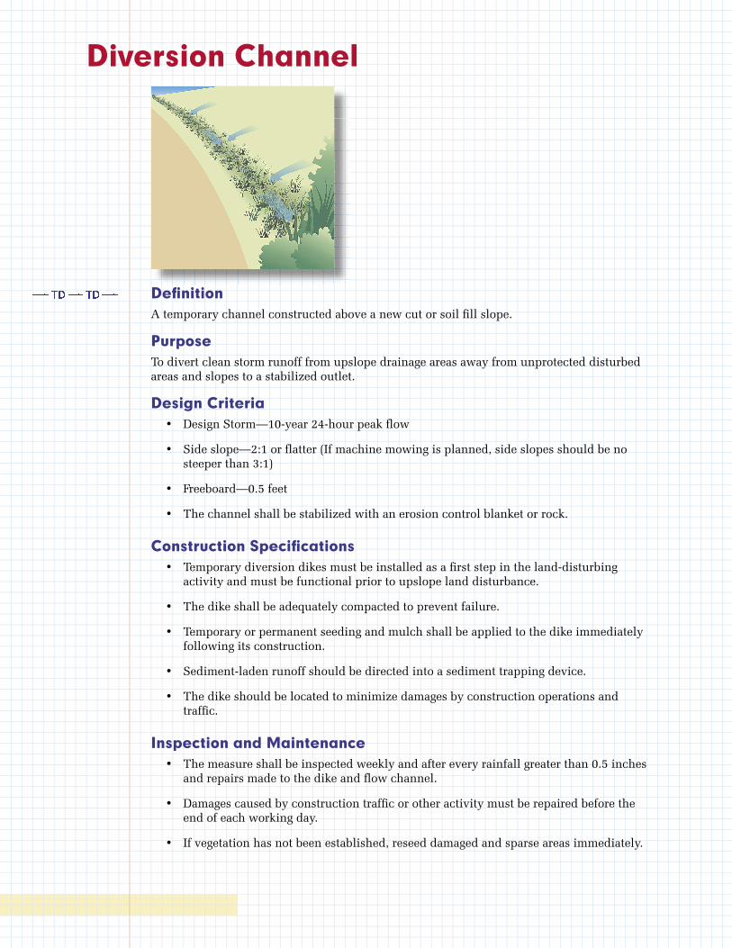
Defi nitionA temporary channel constructed above a new cut or soil fi ll slope.
PurposeTo divert clean storm runoff from upslope drainage areas away from unprotected disturbed areas and slopes to a stabilized outlet.
Design Criteria • Design Storm—10-year 24-hour peak fl ow
• Side slope—2:1 or fl atter (If machine mowing is planned, side slopes should be no steeper than 3:1)
• Freeboard—0.5 feet
• The channel shall be stabilized with an erosion control blanket or rock.
Construction Specifi cations • Temporary diversion dikes must be installed as a fi rst step in the land-disturbing
activity and must be functional prior to upslope land disturbance.
• The dike shall be adequately compacted to prevent failure.
• Temporary or permanent seeding and mulch shall be applied to the dike immediately following its construction.
• Sediment-laden runoff should be directed into a sediment trapping device.
• The dike should be located to minimize damages by construction operations and traffi c.
Inspection and Maintenance • The measure shall be inspected weekly and after every rainfall greater than 0.5 inches
and repairs made to the dike and fl ow channel.
• Damages caused by construction traffi c or other activity must be repaired before the end of each working day.
• If vegetation has not been established, reseed damaged and sparse areas immediately.
Soil Stabilization
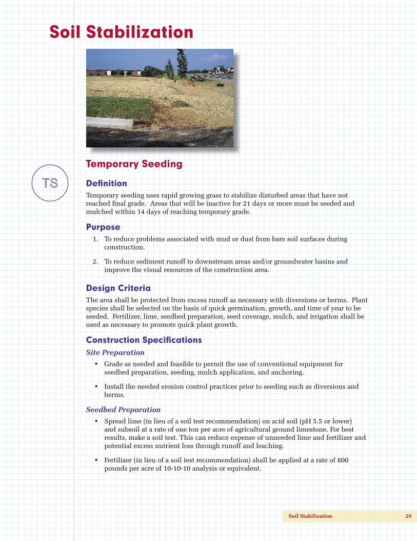
Temporary Seeding
Defi nitionTemporary seeding uses rapid growing grass to stabilize disturbed areas that have not reached fi nal grade. Areas that will be inactive for 21 days or more must be seeded and mulched within 14 days of reaching temporary grade.
Purpose 1. To reduce problems associated with mud or dust from bare soil surfaces during
construction.
2. To reduce sediment runoff to downstream areas and/or groundwater basins and improve the visual resources of the construction area.
Design CriteriaThe area shall be protected from excess runoff as necessary with diversions or berms. Plant species shall be selected on the basis of quick germination, growth, and time of year to be seeded. Fertilizer, lime, seedbed preparation, seed coverage, mulch, and irrigation shall be used as necessary to promote quick plant growth.
Construction Specifi cationsSite Preparation
• Grade as needed and feasible to permit the use of conventional equipment for seedbed preparation, seeding, mulch application, and anchoring.
• Install the needed erosion control practices prior to seeding such as diversions and berms.
Seedbed Preparation
• Spread lime (in lieu of a soil test recommendation) on acid soil (pH 5.5 or lower) and subsoil at a rate of one ton per acre of agricultural ground limestone. For best results, make a soil test. This can reduce expense of unneeded lime and fertilizer and potential excess nutrient loss through runoff and leaching.
• Fertilizer (in lieu of a soil test recommendation) shall be applied at a rate of 800 pounds per acre of 10-10-10 analysis or equivalent.
Soil Stabilization 29
• Work the lime and fertilizer into the soil with a disk harrow, springtooth harrow, or similar tools to a depth of two inches. On sloping areas, the final operation shall be on the contour.
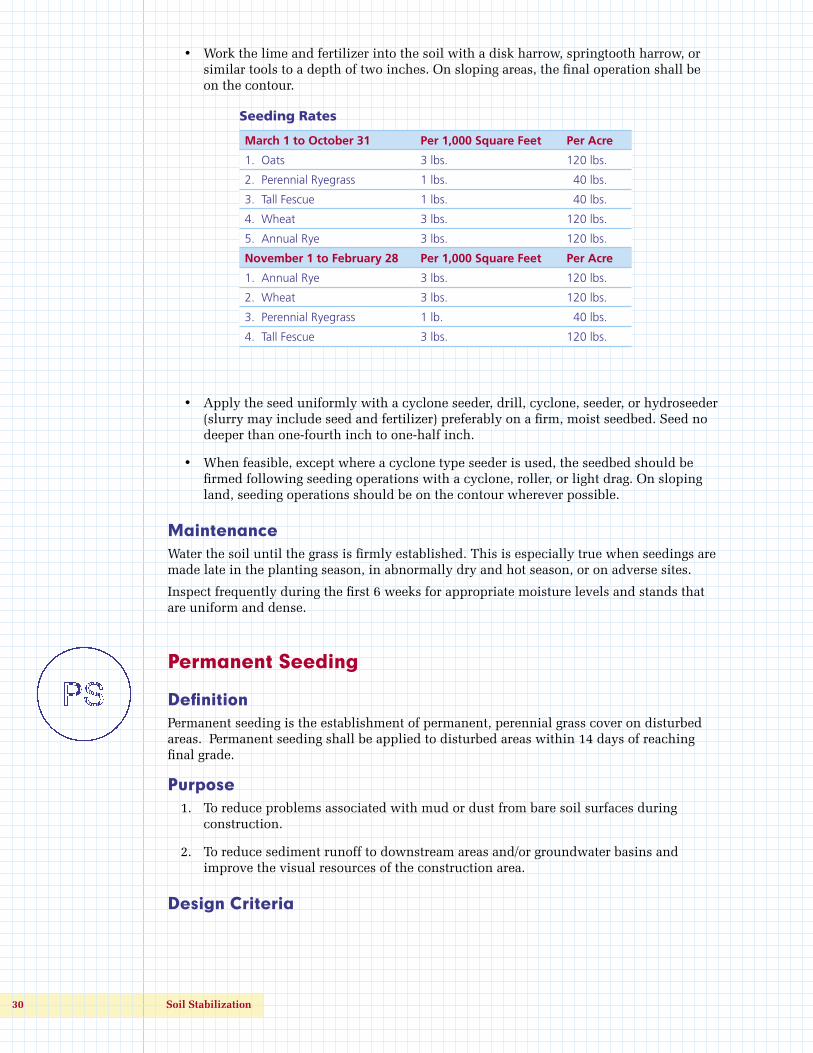
Seeding Rates
March 1 to October 31 Per 1,000 Square Feet Per Acre
1. Oats 3 lbs. 120 lbs.
2. Perennial Ryegrass 1 lbs. 40 lbs.
3. Tall Fescue 1 lbs. 40 lbs.
4. Wheat 3 lbs. 120 lbs.
5. Annual Rye 3 lbs. 120 lbs.
November 1 to February 28 Per 1,000 Square Feet Per Acre
1. Annual Rye 3 lbs. 120 lbs.
2. Wheat 3 lbs. 120 lbs.
3. Perennial Ryegrass 1 lb. 40 lbs.
4. Tall Fescue 3 lbs. 120 lbs.
• Apply the seed uniformly with a cyclone seeder, drill, cyclone, seeder, or hydroseeder (slurry may include seed and fertilizer) preferably on a firm, moist seedbed. Seed no deeper than one-fourth inch to one-half inch.
• When feasible, except where a cyclone type seeder is used, the seedbed should be firmed following seeding operations with a cyclone, roller, or light drag. On sloping land, seeding operations should be on the contour wherever possible.
MaintenanceWater the soil until the grass is firmly established. This is especially true when seedings are made late in the planting season, in abnormally dry and hot season, or on adverse sites.
Inspect frequently during the first 6 weeks for appropriate moisture levels and stands that are uniform and dense.
Permanent Seeding
DefinitionPermanent seeding is the establishment of permanent, perennial grass cover on disturbed areas. Permanent seeding shall be applied to disturbed areas within 14 days of reaching final grade.
Purpose 1. To reduce problems associated with mud or dust from bare soil surfaces during
construction.
2. To reduce sediment runoff to downstream areas and/or groundwater basins and improve the visual resources of the construction area.
Design Criteria
30 Soil Stabilization

The area shall be protected from excess runoff as necessary with diversions or berms. Plant species shall be selected on the basis of quick germination, growth, and time of year to be seeded. Fertilizer, lime, seedbed preparation, seed coverage, mulch, and irrigation shall be used as necessary to promote quick plant growth.
Construction SpecificationsSite Preparation
• Soil material should be capable of supporting permanent vegetation and have at least 25 percent silt and clay to provide an adequate amount of moisture holding capacity. An excessive amount of porous sand will not consistently provide sufficient moisture for good growth regardless of other soil factors.
• Where compacted soils occur, they should be broken up sufficiently to create a favorable rooting depth of 6-8 inches.
• Stockpile topsoil to apply to sites that are otherwise unsuited for establishing vegetation (Stabilize stockpiles with temporary vegetation).
• Grade as needed and feasible to permit the use of conventional equipment for seedbed preparation, seeding, mulch application and anchoring, and maintenance. After the grading operation, spread topsoil where needed.
• Install the needed erosion control practices such as diversions and berms.
Seedbed Preparation
• Spread lime (in lieu of a soil test recommendation) on acid soil and subsoil, at a rate of one ton per acre of agricultural ground limestone. For best results, make a soil test. This can reduce expense of unneeded lime and fertilizer and potential excess nutrient loss through runoff and leaching.
• Fertilizer (in lieu of a soil test recommendation) shall be applied at a rate of 800 pounds per acre of 10-10-10 analysis. For best results, make a soil test.
• Work the lime and fertilizer into the soil with a disk harrow, springtooth harrow, or other suitable field equipment to a depth of 4 inches. On sloping land, the final operation shall be on the contour.
Suggested Seeding Rates
Seed species & mixtures Seeding rate/acre Per 1000 sq ft
Seed and seed mixtures for relatively flat or slightly sloping areas
Perennial ryegrass+ tall fescueTall fescue+ ladino or white clover
25 to 35 lbs15 to 30 lbs40 to 50 lbs1 to 2 lbs
1 lb1 lb1.5 lb2 oz
Steep slopes, banks, cuts, and other low maintenance areas (not mowed)
Smooth bromegrass+ red cloverTall fescue+ white or ladino cloverOrchardgrass+ red clover+ ladino cloverCrownvetch+ tall fescue
25 to 35 lbs10 to 20 lbs40 to 50 lbs1 to 2 lbs20 to 30 lbs10 to 20 lbs1 to 2 lbs10 to 12 lbs20 to 30 lbs
1 lb0.5 lb1 lb2 oz1 lb0.5 lb2 oz0.25 lb1 lb
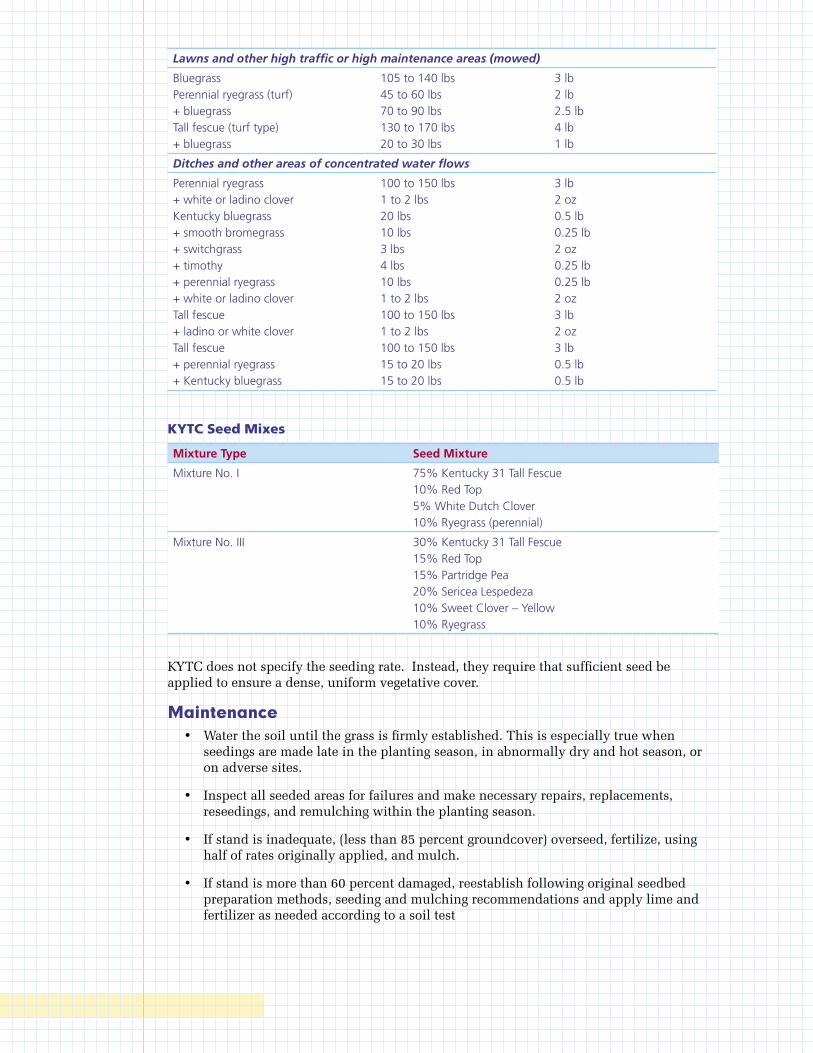
Lawns and other high traffic or high maintenance areas (mowed)
BluegrassPerennial ryegrass (turf)+ bluegrassTall fescue (turf type)+ bluegrass
105 to 140 lbs45 to 60 lbs70 to 90 lbs130 to 170 lbs20 to 30 lbs
3 lb2 lb2.5 lb4 lb1 lb
Ditches and other areas of concentrated water flows
Perennial ryegrass+ white or ladino cloverKentucky bluegrass+ smooth bromegrass+ switchgrass+ timothy+ perennial ryegrass+ white or ladino cloverTall fescue+ ladino or white cloverTall fescue+ perennial ryegrass+ Kentucky bluegrass
100 to 150 lbs1 to 2 lbs20 lbs10 lbs3 lbs4 lbs10 lbs1 to 2 lbs100 to 150 lbs1 to 2 lbs100 to 150 lbs15 to 20 lbs15 to 20 lbs
3 lb2 oz0.5 lb0.25 lb2 oz0.25 lb0.25 lb2 oz3 lb2 oz3 lb0.5 lb0.5 lb
KYTC Seed Mixes
Mixture Type Seed Mixture
Mixture No. I 75% Kentucky 31 Tall Fescue10% Red Top5% White Dutch Clover10% Ryegrass (perennial)
Mixture No. III 30% Kentucky 31 Tall Fescue15% Red Top15% Partridge Pea20% Sericea Lespedeza10% Sweet Clover – Yellow10% Ryegrass
KYTC does not specify the seeding rate. Instead, they require that sufficient seed be applied to ensure a dense, uniform vegetative cover.
Maintenance • Water the soil until the grass is firmly established. This is especially true when
seedings are made late in the planting season, in abnormally dry and hot season, or on adverse sites.
• Inspect all seeded areas for failures and make necessary repairs, replacements, reseedings, and remulching within the planting season.
• If stand is inadequate, (less than 85 percent groundcover) overseed, fertilize, using half of rates originally applied, and mulch.
• If stand is more than 60 percent damaged, reestablish following original seedbed preparation methods, seeding and mulching recommendations and apply lime and fertilizer as needed according to a soil test
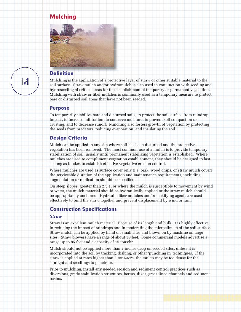
Mulching
Defi nitionMulching is the application of a protective layer of straw or other suitable material to the soil surface. Straw mulch and/or hydromulch is also used in conjunction with seeding and hydroseeding of critical areas for the establishment of temporary or permanent vegetation. Mulching with straw or fi ber mulches is commonly used as a temporary measure to protect bare or disturbed soil areas that have not been seeded.
PurposeTo temporarily stabilize bare and disturbed soils, to protect the soil surface from raindrop impact, to increase infi ltration, to conserve moisture, to prevent soil compaction or crusting, and to decrease runoff. Mulching also fosters growth of vegetation by protecting the seeds from predators, reducing evaporation, and insulating the soil.
Design CriteriaMulch can be applied to any site where soil has been disturbed and the protective vegetation has been removed. The most common use of a mulch is to provide temporary stabilization of soil, usually until permanent stabilizing vegetation is established. Where mulches are used to compliment vegetation establishment, they should be designed to last as long as it takes to establish effective vegetative erosion control.
Where mulches are used as surface cover only (i.e. bark, wood chips, or straw mulch cover) the serviceable duration of the application and maintenance requirements, including augmentation or replication should be specifi ed.
On steep slopes, greater than 2.5:1, or where the mulch is susceptible to movement by wind or water, the mulch material should be hydraulically applied or the straw mulch should be appropriately anchored. Hydraulic fi ber mulches and/or tackifying agents are used effectively to bind the straw together and prevent displacement by wind or rain.
Construction Specifi cationsStraw
Straw is an excellent mulch material. Because of its length and bulk, it is highly effective in reducing the impact of raindrops and in moderating the microclimate of the soil surface. Straw mulch can be applied by hand on small sites and blown on by machine on large sites. Straw blowers have a range of about 50 feet. Some commercial models advertise a range up to 85 feet and a capacity of 15 tons/hr.
Mulch should not be applied more than 2 inches deep on seeded sites, unless it is incorporated into the soil by tracking, disking, or other ‘punching in’ techniques. If the straw is applied at rates higher than 3 tons/acre, the mulch may be too dense for the sunlight and seedlings to penetrate.
Prior to mulching, install any needed erosion and sediment control practices such as diversions, grade stabilization structures, berms, dikes, grass-lined channels and sediment basins.
Defi nitionDefi nitionDefi nitionDefi nitionDefi nitionDefi nitionDefi nition
• Obtain clean wheat, barley, oat, or rice straw in order to prevent the spread of noxious weeds. Avoid moldy, compacted straw because it tends to clump and is not distributed evenly.
• The straw shall be evenly distributed by hand or machine to the desired depth of 2-4 inches and should cover the exposed area to a uniform depth.
• Approximately one bale (approximately 80 lbs) of straw covers 1000 ft2 adequately. The soil surface should be barely visible through the straw mulch. On steep or high wind sites, straw must be anchored to keep it from blowing away.
• For seeded sites, apply: 1.5-2 tons/acre, 1-2 inches deep, covering 80% of the soil surface.
• For unseeded sites: 2-3 tons/acre, 2-4 inches deep, covering 90% of the soil surface.
Anchoring
Mulch must be anchored immediately to minimize loss by wind or water. Straw mulch is commonly anchored by:
• crimping, tracking, disking, or punching into the soil;
• covering with a netting;
• spraying with asphaltic or organic tackifier;
• tacking with cellulose fiber mulch at a rate of 750 lbs/ac
Crimping
• On small sites, where straw has been distributed by hand, it can be anchored by hand punching it into the soil every 1-2 feet with a dull, round-nosed shovel. A sharp shovel will merely cut the straw and not anchor it.
• A mulch anchoring tool is a tractor drawn implement designed to punch and anchor mulch into the top 2-8 inches of soil. This practice affords maximum erosion control but is limited to flatter slopes where equipment can operate safely.
• Tracking is the process of cutting straw into the soil using a bulldozer or other equipment that runs on cleated tracks. Tracking is used primarily on slopes 3:1 or flatter where this type of equipment can safely operate. This is an effective way to crimp straw on fill slopes. Tracking equipment must operate up and down the slope so the cleat tracks are perpendicular to flow.
Nettings
• Nettings of biodegradable paper, plastic or cotton netting can be used to cover straw mulch. Netting should be specified judiciously since birds, snakes and other wildlife can get trapped in the nettings.
Tackifiers
• Polymer tackifiers are generally applied at rates of 40-60 lbs/ac, however manufacturers recommendations vary.
• Organic tackifiers are generally applied at rates of 80-120 lbs/acre, however manufacturer’s recommendations vary.
• Applications of liquid mulch binders shall be heavier at edges, in valleys, and at crests of banks and other areas where the mulch may be moved by wind or water. All other areas shall have a uniform application of the tackifier.

Wood Chips or Bark
• Apply at a rate of approximately 6 tons/acre.
• The mulch should be evenly distributed across the soil surface to a depth of 2-3 inches.
• If decomposition, soil building and re-vegetation are desirable, increase the application rate of nitrogen fertilizer by 20 lbs. of N/acre, to compensate for the temporary diversion (loss) of available N to the soil microbes.
Hydraulic Mulches from Recycled Paper
This mulch is made from recycled newsprint, magazine, or other waste paper sources. This type of mulch is to be mixed in a hydraulic application machine (hydroseeder) and applied as a liquid slurry that contains the recommended rates of seed and fertilizer for the site. It can be specified with or without a tackifier.
• Apply at rate of 1.5 tons/ac, mixed with seed and fertilizer, at recommended rates, in order to achieve uniform, effective coverage.
• Paper mulch used to tack and bind straw mulch can be specified at a lower rate, 750 lbs/ac.
Hydraulic Mulches from Wood Fiber
This type of mulch is manufactured from wood waste. This type of mulch is also to be mixed in a hydraulic application machine (hydroseeder) and applied as a liquid slurry that contains the recommended rates of seed and fertilizer for the site. A wood fiber mulch can be manufactured containing a tackifier in each bag or specified without a tackifier.
Hydraulic Mulches from Wood and Paper Fiber
These combination mulches are generally comprised of 70% wood fiber and 30% paper fiber, manufactured from lumber mill waste, virgin wood chips, recycled newsprint, office paper and other waste paper. The mulch is mixed in a hydraulic application machine (hydroseeder) and applied as a slurry in combination with the recommended seed and fertilizer. The mulch can be specified with or without a tackifier.
Recommendations
Wood, paper or combination fiber mulches are typically applied with a hydraulic applicator (hydroseeder) at a minimum rate of 1.5 tons/ac.
A typical construction specification and application for mulch is as follows:
• Moisture content (total weight basis) not to exceed 12% +/- 3%.
• Organic matter content (oven dry weight basis) is 98% minimum.
• Inorganic matter (ash) content (oven dried basis) 2% maximum.
• pH at 3% consistently in water should be 4.9.
• Fiber shall be dyed to aid visual metering during application. The dye shall be biodegradable and shall not inhibit plant growth.
• Water holding capacity (oven dried basis) minimum 1.0 gal/lb of fiber.
• The mulch shall be mixed with seed and fertilizer as specified and applied at a rate recommended by the manufacturer in order to achieve uniform, effective coverage and provide adequate distribution of seed.
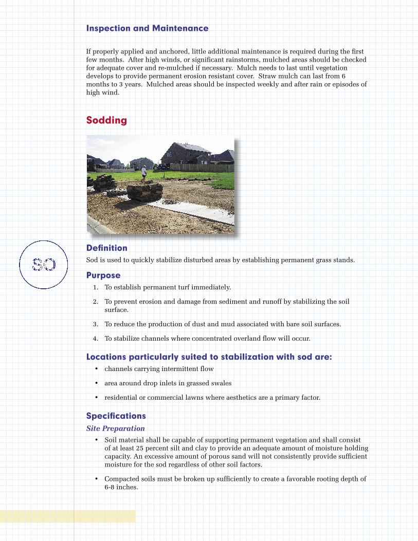
Inspection and Maintenance
If properly applied and anchored, little additional maintenance is required during the fi rst few months. After high winds, or signifi cant rainstorms, mulched areas should be checked for adequate cover and re-mulched if necessary. Mulch needs to last until vegetation develops to provide permanent erosion resistant cover. Straw mulch can last from 6 months to 3 years. Mulched areas should be inspected weekly and after rain or episodes of high wind.
Sodding
Defi nitionSod is used to quickly stabilize disturbed areas by establishing permanent grass stands.
Purpose 1. To establish permanent turf immediately.
2. To prevent erosion and damage from sediment and runoff by stabilizing the soil surface.
3. To reduce the production of dust and mud associated with bare soil surfaces.
4. To stabilize channels where concentrated overland fl ow will occur.
Locations particularly suited to stabilization with sod are: • channels carrying intermittent fl ow
• area around drop inlets in grassed swales
• residential or commercial lawns where aesthetics are a primary factor.
Specifi cationsSite Preparation
• Soil material shall be capable of supporting permanent vegetation and shall consist of at least 25 percent silt and clay to provide an adequate amount of moisture holding capacity. An excessive amount of porous sand will not consistently provide suffi cient moisture for the sod regardless of other soil factors.
• Compacted soils must be broken up suffi ciently to create a favorable rooting depth of 6-8 inches.

• Stockpile topsoil to apply to sites that are otherwise unsuited for establishing vegetation.
• Grade as needed and feasible to permit the use of conventional equipment for the sod bed preparation. After the grading operation, spread topsoil where needed.
Sod Bed Preparation
• Apply lime (in lieu of a soil test) on acid soil and subsoil at a rate of one ton per acre. The lime should be agricultural ground limestone or equivalent. For best results, conduct a soil test. This can reduce expense of unneeded lime and fertilizer and potential excess nutrient loss through runoff and leaching.
• Apply fertilizer (in lieu of a soil test) at 1,000 pounds per acre of 10-10-10 analysis. For best results, conduct a soil test.
• Work lime and fertilizer into the soil with a disk harrow, springtooth harrow, or other suitable field equipment to a depth of four inches.
• Prior to sodding, the soil surface shall be cleared of all trash, debris, and stones larger than one and one-half inches in diameter, and of all roots, brush, wire, and other objects that would interfere with the placing of the sod.
• After the lime and fertilizer have been applied and just prior to the laying of the sod, the soil in the area to be sodded shall be loosened to a depth of one inch. The soil shall be thoroughly dampened immediately after the sod is laid if it is not already in a moist condition.
Cutting and Handling of Sod
• The sod should consist of strips of live, vigorously growing grasses. The sod should be free of noxious and secondary noxious weeds and should be obtained from good, solid, thick-growing stands. The sod should be cut and transferred to the job in as large continuous pieces as will hold together and are practical to handle.
• The sod shall be cut with smooth clean edges and square ends to facilitate laying and fitting. The sod shall be cut to a uniform thickness of not less than three-fourth inch measured from the crown of the plants to the bottom of the sod strips for all grasses except bluegrass. Bluegrass sod shall be cut to a uniform thickness of not less than one and one-half inches.
• The sod shall be mowed to a height of not less than two inches and no more than four inches prior to cutting.
• The sod shall be kept moist and covered during hauling and preparation for placement on the sod bed.
Placing of Sod
• No sod shall be placed when the temperature is below 32°F. No frozen sod shall be placed nor shall any sod be placed on frozen soil.
• Sod shall be carefully placed and pressed together so it will be continuous without any voids between the pieces. Joints between the ends of strips shall be staggered. The edge of the sod at the outer edges of all gutters shall be sufficiently deep so that the surface water will flow over onto the top of the sod.
• On gutter and channel sodding, the sod should be carefully placed on rows or strips at right angles to the centerline of the channel (i.e., at right angles to the direction of flow). On steep graded channels, each strip of sod shall be staked with at least
two stakes not more than 18 inches apart. The stakes shall be wood and shall be approximately 1/2” X 3/4” X 12”. They shall be driven flush with the top of the sod and with the flat side against the slope.
• On slopes 3:1, or steeper, and where drainage into a sod gutter or channel is one-half acre or larger, the sod shall be rolled or tamped and then chicken wire, jute, or other netting pegged over the sod for protection in the critical areas. The netting and sod shall be staked with at least two stakes not more than 18 inches apart. The stakes shall be wood arid be approximately 1/2” X 3/4” X 12”. They shall be driven with the flat side against the slope and on an angle toward the slope. The netting shall be stapled on the side of each stake within two inches of the top of the stake. The stake should then be driven flush with the top of the sod.
• The sod shall be tamped or rolled after placing and then watered. Watering shall consist of a thorough soaking of the sod and of the sod bed to a depth of at least 4 inches. The sod should be maintained in a moist condition by watering for a period of 30 days.
MaintenanceWhere sodding does not establish properly, the area should be sodded again as soon as possible. The cause of the failure should be identified and corrected as soon as possible.
Once established, a regular maintenance program for fertilization and mowing of grasses should be performed.
Topsoil Stockpiling
DefinitionStockpiling is the salvaging, storing, protecting, and using topsoil to enhance final site stabilization with vegetation.
PurposeThe purpose of stockpiling is to provide a suitable growth medium for vegetation. It should be used where the subsoil or areas of existing surface soil present the following problems:
• The structure, pH, or nutrient balance of the available soil cannot be amended by reasonable means to provide an adequate growth medium for the desired vegetation.
• The soil is too shallow to provide adequate rooting depth or will not supply necessary moisture and nutrients for growth of desired vegetation.
• The soil contains substances toxic to the desired vegetation.
Stockpiling should also be used where high-quality turf or ornamental plants are desired, and where slopes are 2:1 or flatter.
Topsoil is the surface layer of the soil profile, generally characterized as darker than the subsoil due to enrichment with organic matter. It is the major zone of root development and biological activity. Microorganisms that enhance plant growth thrive in this layer. Topsoil can usually be differentiated from subsoil by texture as well as color. Clay content usually increases in the subsoil. Where subsoils are often high in clay, the topsoil layer may be significantly coarser in texture. The depth of topsoil may be quite variable. On severely eroded sites, it may be gone entirely.
Advantages of topsoil include its high organic-matter content and friable consistence (soil aggregates can be crushed with only moderate pressure), and its available water-holding capacity and nutrient content. Most often it is superior to subsoil in these characteristics.
The texture and friability of topsoil are usually much better to the seed emerging and root growth.
In addition to being a better growth medium, topsoil is often less erodible than subsoils, and the coarser texture of topsoil increases infiltration capacity and reduces runoff.
Although topsoil may provide an improved growth medium, there may be disadvantages, too. Stripping, stockpiling, hauling, and spreading topsoil, or importing topsoil may not be cost effective. Handling may be difficult if large amounts of branches or rocks are present, or if the terrain is too rough. Most topsoil contains weed seeds that compete with desirable species.
In site planning, compare the options of stockpiling with preparing a seedbed in the available subsoil. The clay content of many subsoils retains moisture. When properly limed and fertilized, subsoils may provide a satisfactory growth medium that is generally free of weed seeds.
Stockpiling is normally recommended where ornamental plants or high-maintenance turf will be grown. It may also be required to establish vegetation on shallow soils, soils containing potentially toxic materials, stony soils, and soils of critically low pH (high acidity).
Design CriteriaIf topsoil is to be stockpiled, consider the following:
• quality and amount of topsoil available and needed,
• location for a stabilized stockpile that will not erode, block drainage, or interfere with work on the site.
• if topsoil and subsoil are not properly bonded, water will not infiltrate the soil profile evenly, and it will be difficult to establish vegetation.
• do not apply topsoil to slopes steeper than 2:1 to avoid slippage, or to a subsoil of highly contrasting texture. Sandy topsoil over clay subsoil is a particularly poor combination especially on steep slope. Water may creep along the junction between the soil layers and cause the topsoil to slough.
Construction SpecificationsMaterials
Quality topsoil has the following characteristics:
• The best texture is loam, sandy loam, and silt loam. Sandy clay loam, silty clay loam, clay loam, and loamy sand are fair. Do not use heavy clay and organic soils such as peat or muck as topsoil.
• Organic matter content should be greater than 1 percent by weight.
• pH should be greater than 3.6 before liming, and liming is required if pH is less than 6.0.
The depth of material meeting the above qualifications should be at least 2 inches. Soil factors such as rock fragments, slope, depth to water table, and layer thickness affect the ease of excavation and spreading of topsoil.
Generally, the upper part of the soil that is richest in organic matter is most desirable; however, material excavated from deeper layers may be worth storing if it meets the other criteria listed above.
Organic soils such as mucks and peats do not make good topsoil. They can be identified by their extremely light weight when dry.
Stripping
Strip topsoil only from those areas that will be disturbed by excavation, filling, roadbuilding, or compaction by equipment. A 4-6 inch stripping depth is common, but depth varies depending on the site. Determine depth of stripping by taking soil cores at several locations within each area to be stripped. Topsoil depth generally varies along a gradient from hilltop to toe of slope. Put sediment basins, diversions, and other controls into place before stripping.
Stockpiling
• Select stockpile location to avoid slopes, flood plains, natural channels, and traffic routes. Stockpiles should be placed away from water bodies to prevent sedimentation. On large sites, re-spreading is easier and more economical when topsoil is stockpiled in small piles located near areas where they will be used.
• Use silt fences or other barriers where necessary to retain sediment.
• Protect topsoil stockpiles by temporarily seeding as soon as possible, and no more than 30 days after the formation of the stockpile.
• If stockpiles will not be used within 12 months, they should be stabilized with permanent vegetation to control erosion and weed growth.
Site Preparation
• Before spreading topsoil, establish erosion and sedimentation control practices such as diversions, berms, and sediment basins.
• Maintain grades on the areas to be topsoiled according to the approved plan. Adjust grades and elevations for receipt of topsoil.
• Where the pH of the existing subsoil is 6.0 or less, or the soil is composed of heavy clays, incorporate agricultural limestone in amounts recommended by soil tests or specified for the seeding mixture to be used. Incorporate lime to a depth of at least 2 inches by disking.
• Immediately prior to spreading the topsoil, loosen the subgrade by disking or scarifying to a depth of at least 4 inches to ensure bonding of the topsoil and subsoil. If no amendments have been incorporated, loosen the soil to a depth of at least 6 inches before spreading topsoil.
Spreading Topsoil
• Uniformly distribute topsoil to a minimum compact depth of 2 inches on 3:1 slopes and 4 inches on flatter slopes. Do not spread topsoil while it is frozen or muddy or when the subgrade is wet or frozen.
• Correct any irregularities in the surface that result from stockpiling or other operations to prevent the formation of depressions or water pockets.
• Compact the topsoil enough to ensure good contact with the underlying soil, but avoid excessive compaction as it increases runoff and inhibits seed germination. Light packing with a roller is recommended where high-maintenance turf is to be established.
• On slopes and areas that will not be mowed, the surface may be left rough after spreading topsoil. A disk may be used to promote bonding at the interface between the topsoil and subsoil.
• After topsoil application, follow procedures for temporary or permanent seeding, taking care to avoid excessive mixing of topsoil into the subsoil.
Dust Control
DefinitionDust control is the reducing of surface and air movement of dust during land disturbing, demolition and other construction activities.
PurposeThe purpose of dust control is to prevent the air movement of sediments to off-site areas or other on-site areas without sediment control where they could subsequently be washed into surface waters. Dust control should be planned in association with earthmoving/site grading activities and areas with frequent construction traffic.
Design CriteriaConstruction activities shall be phased to minimize the total area unstabilized at any given time, thereby reducing erosion due to air and water movement.
Existing trees, shrubs, and ground cover shall be retained as long as possible during the construction. Initial land clearing should be conducted only in those areas to be regraded or where construction is to occur. Areas to be cleared only for new vegetation or landscaping shall be stabilized with seed and mulch immediately following clearing.
Vegetative cover is the most effective means of dust and erosion control, when appropriate. See sections on Temporary Seed, Permanent Seed, Mulch, and Sod in this manual.
When areas have been regraded and brought to final grade, they shall be stabilized using temporary or permanent seed and mulch or other measures.
Mulch with mulch binders may be used as an interim dust control measure in areas where vegetation may not be appropriate.
Construction SpecificationsSee sections on Temporary Seed, Permanent Seed, Sod, Mulch, and Construction Entrance.
Construction roads shall be watered as needed to minimize dust.
Inspection and Maintenance The site should be observed daily for evidence of windblown dust and reasonable steps should be taken to reduce dust whenever possible. When construction on a site is inactive for a period, the site should be inspected at least weekly for evidence of dust emissions or previously windblown sediments. Dust control measures must be implemented or upgraded if the site inspection shows evidence of wind erosion.
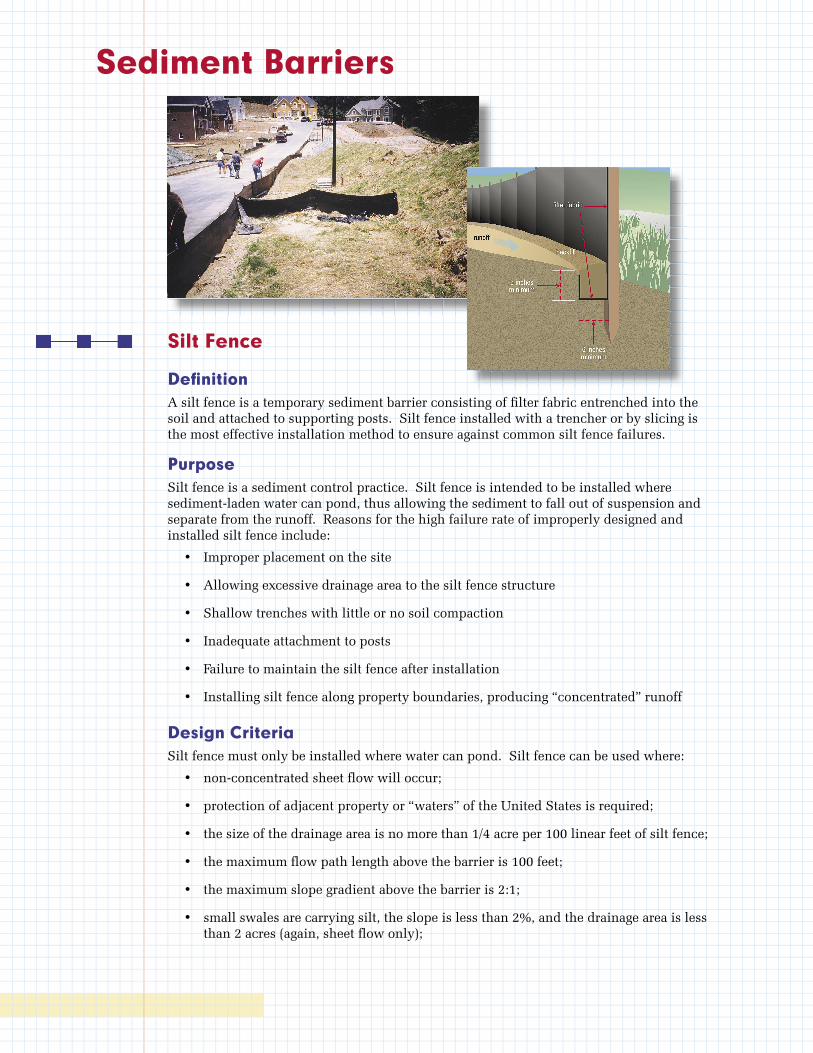
Sediment Barriers
Silt Fence
Defi nitionA silt fence is a temporary sediment barrier consisting of fi lter fabric entrenched into the soil and attached to supporting posts. Silt fence installed with a trencher or by slicing is the most effective installation method to ensure against common silt fence failures.
Purpose Silt fence is a sediment control practice. Silt fence is intended to be installed where sediment-laden water can pond, thus allowing the sediment to fall out of suspension and separate from the runoff. Reasons for the high failure rate of improperly designed and installed silt fence include:
• Improper placement on the site
• Allowing excessive drainage area to the silt fence structure
• Shallow trenches with little or no soil compaction
• Inadequate attachment to posts
• Failure to maintain the silt fence after installation
• Installing silt fence along property boundaries, producing “concentrated” runoff
Design Criteria Silt fence must only be installed where water can pond. Silt fence can be used where:
• non-concentrated sheet fl ow will occur;
• protection of adjacent property or “waters” of the United States is required;
• the size of the drainage area is no more than 1/4 acre per 100 linear feet of silt fence;
• the maximum fl ow path length above the barrier is 100 feet;
• the maximum slope gradient above the barrier is 2:1;
• small swales are carrying silt, the slope is less than 2%, and the drainage area is less than 2 acres (again, sheet fl ow only);
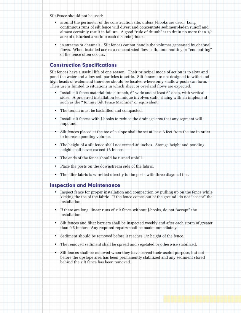
Silt Fence should not be used:
• around the perimeter of the construction site, unless J-hooks are used. Long continuous runs of silt fence will divert and concentrate sediment-laden runoff and almost certainly result in failure. A good “rule of thumb” is to drain no more than 1/3 acre of disturbed area into each discrete J-hook;
• in streams or channels. Silt fences cannot handle the volumes generated by channel flows. When installed across a concentrated flow path, undercutting or “end cutting” of the fence often occurs.
Construction SpecificationsSilt fences have a useful life of one season. Their principal mode of action is to slow and pond the water and allow soil particles to settle. Silt fences are not designed to withstand high heads of water, and therefore should be located where only shallow pools can form. Their use is limited to situations in which sheet or overland flows are expected.
• Install silt fence material into a trench, 6” wide and at least 6” deep, with vertical sides. A preferred installation technique involves static slicing with an implement such as the “Tommy Silt Fence Machine” or equivalent.
• The trench must be backfilled and compacted.
• Install silt fences with J-hooks to reduce the drainage area that any segment will impound
• Silt fences placed at the toe of a slope shall be set at least 6 feet from the toe in order to increase ponding volume.
• The height of a silt fence shall not exceed 36 inches. Storage height and ponding height shall never exceed 18 inches.
• The ends of the fence should be turned uphill.
• Place the posts on the downstream side of the fabric.
• The filter fabric is wire-tied directly to the posts with three diagonal ties.
Inspection and Maintenance • Inspect fence for proper installation and compaction by pulling up on the fence while
kicking the toe of the fabric. If the fence comes out of the ground, do not “accept” the installation.
• If there are long, linear runs of silt fence without J-hooks, do not “accept” the installation.
• Silt fences and filter barriers shall be inspected weekly and after each storm of greater than 0.5 inches. Any required repairs shall be made immediately.
• Sediment should be removed before it reaches 1/2 height of the fence.
• The removed sediment shall be spread and vegetated or otherwise stabilized.
• Silt fences shall be removed when they have served their useful purpose, but not before the upslope area has been permanently stabilized and any sediment stored behind the silt fence has been removed.
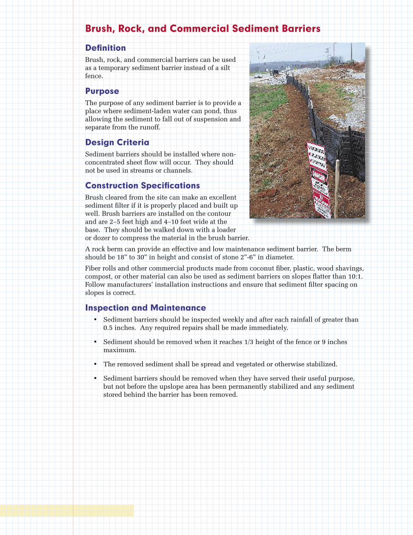
Brush, Rock, and Commercial Sediment Barriers
Defi nitionBrush, rock, and commercial barriers can be used as a temporary sediment barrier instead of a silt fence.
Purpose The purpose of any sediment barrier is to provide a place where sediment-laden water can pond, thus allowing the sediment to fall out of suspension and separate from the runoff.
Design Criteria Sediment barriers should be installed where non-concentrated sheet fl ow will occur. They should not be used in streams or channels.
Construction Specifi cationsBrush cleared from the site can make an excellent sediment fi lter if it is properly placed and built up well. Brush barriers are installed on the contour and are 2–5 feet high and 4–10 feet wide at the base. They should be walked down with a loader or dozer to compress the material in the brush barrier.
A rock berm can provide an effective and low maintenance sediment barrier. The berm should be 18” to 30” in height and consist of stone 2”-6” in diameter.
Fiber rolls and other commercial products made from coconut fi ber, plastic, wood shavings, compost, or other material can also be used as sediment barriers on slopes fl atter than 10:1. Follow manufacturers’ installation instructions and ensure that sediment fi lter spacing on slopes is correct.
Inspection and Maintenance • Sediment barriers should be inspected weekly and after each rainfall of greater than
0.5 inches. Any required repairs shall be made immediately.
• Sediment should be removed when it reaches 1/3 height of the fence or 9 inches maximum.
• The removed sediment shall be spread and vegetated or otherwise stabilized.
• Sediment barriers should be removed when they have served their useful purpose, but not before the upslope area has been permanently stabilized and any sediment stored behind the barrier has been removed.
Slope Protection
Erosion Control Blankets and Mats
Defi nitionThe installation of protective mulch blankets or soil stabilization mats (turf reinforcement mats) to the prepared soil surface of a steep slope, channel or shoreline.
PurposeErosion control blankets are used to temporarily stabilize and protect disturbed soil from raindrop impact and surface erosion, to increase infi ltration, decrease compaction and soil crusting, and to conserve soil moisture. Mulching with erosion control blankets will increase the germination rates for grasses and legumes and promote vegetation establishment. Erosion control blankets also protect seeds from predators, reduce desiccation and evaporation by insulating the soil and seed environment.
Some types of erosion control blankets and turf reinforcement mats are specifi cally designed to stabilize channelized fl ow areas. These blankets and mats can aid the establishment of vegetation in waterways and increase the maximum permissible velocity of the given channel by reinforcing the soil and vegetation to resist the forces of erosion during runoff events. Stems, roots and rhizomes of the vegetation become intertwined with the mat, reinforcing the vegetation and anchoring the mat.
Design CriteriaThe table at the end of this section provides guidance on the application of various blankets and mats.
An erosion control blanket or mat should be used in all drainage channels and in the following conditions:
• Slopes and disturbed soils where mulch must be anchored and other methods such as crimping or tackifying are not feasible nor adequate.
• Steep slopes, generally steeper than 3:1.
• Slopes where erosion hazard is high.
• Critical slopes adjacent to sensitive areas such as streams and wetlands.
• Disturbed soil areas where planting is likely to be slow in providing adequate protective cover.
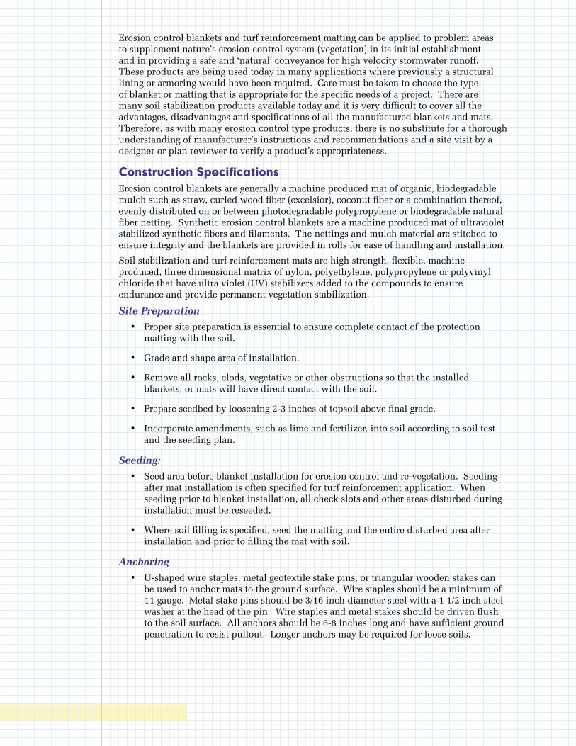
Erosion control blankets and turf reinforcement matting can be applied to problem areas to supplement nature’s erosion control system (vegetation) in its initial establishment and in providing a safe and ‘natural’ conveyance for high velocity stormwater runoff. These products are being used today in many applications where previously a structural lining or armoring would have been required. Care must be taken to choose the type of blanket or matting that is appropriate for the specific needs of a project. There are many soil stabilization products available today and it is very difficult to cover all the advantages, disadvantages and specifications of all the manufactured blankets and mats. Therefore, as with many erosion control type products, there is no substitute for a thorough understanding of manufacturer’s instructions and recommendations and a site visit by a designer or plan reviewer to verify a product’s appropriateness.
Construction SpecificationsErosion control blankets are generally a machine produced mat of organic, biodegradable mulch such as straw, curled wood fiber (excelsior), coconut fiber or a combination thereof, evenly distributed on or between photodegradable polypropylene or biodegradable natural fiber netting. Synthetic erosion control blankets are a machine produced mat of ultraviolet stabilized synthetic fibers and filaments. The nettings and mulch material are stitched to ensure integrity and the blankets are provided in rolls for ease of handling and installation.
Soil stabilization and turf reinforcement mats are high strength, flexible, machine produced, three dimensional matrix of nylon, polyethylene, polypropylene or polyvinyl chloride that have ultra violet (UV) stabilizers added to the compounds to ensure endurance and provide permanent vegetation stabilization.
Site Preparation
• Proper site preparation is essential to ensure complete contact of the protection matting with the soil.
• Grade and shape area of installation.
• Remove all rocks, clods, vegetative or other obstructions so that the installed blankets, or mats will have direct contact with the soil.
• Prepare seedbed by loosening 2-3 inches of topsoil above final grade.
• Incorporate amendments, such as lime and fertilizer, into soil according to soil test and the seeding plan.
Seeding:
• Seed area before blanket installation for erosion control and re-vegetation. Seeding after mat installation is often specified for turf reinforcement application. When seeding prior to blanket installation, all check slots and other areas disturbed during installation must be reseeded.
• Where soil filling is specified, seed the matting and the entire disturbed area after installation and prior to filling the mat with soil.
Anchoring
• U-shaped wire staples, metal geotextile stake pins, or triangular wooden stakes can be used to anchor mats to the ground surface. Wire staples should be a minimum of 11 gauge. Metal stake pins should be 3/16 inch diameter steel with a 1 1/2 inch steel washer at the head of the pin. Wire staples and metal stakes should be driven flush to the soil surface. All anchors should be 6-8 inches long and have sufficient ground penetration to resist pullout. Longer anchors may be required for loose soils.
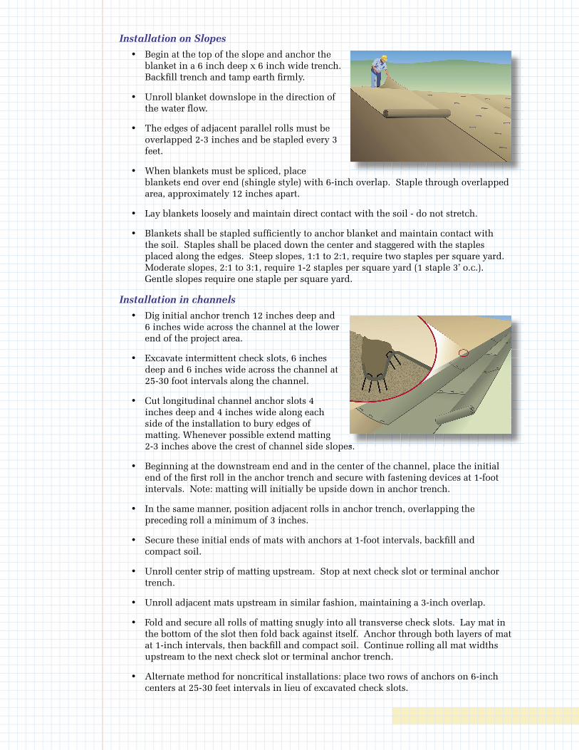
Installation on Slopes
• Begin at the top of the slope and anchor the blanket in a 6 inch deep x 6 inch wide trench. Backfi ll trench and tamp earth fi rmly.
• Unroll blanket downslope in the direction of the water fl ow.
• The edges of adjacent parallel rolls must be overlapped 2-3 inches and be stapled every 3 feet.
• When blankets must be spliced, place blankets end over end (shingle style) with 6-inch overlap. Staple through overlapped area, approximately 12 inches apart.
• Lay blankets loosely and maintain direct contact with the soil - do not stretch.
• Blankets shall be stapled suffi ciently to anchor blanket and maintain contact with the soil. Staples shall be placed down the center and staggered with the staples placed along the edges. Steep slopes, 1:1 to 2:1, require two staples per square yard. Moderate slopes, 2:1 to 3:1, require 1-2 staples per square yard (1 staple 3’ o.c.). Gentle slopes require one staple per square yard.
Installation in channels
• Dig initial anchor trench 12 inches deep and 6 inches wide across the channel at the lower end of the project area.
• Excavate intermittent check slots, 6 inches deep and 6 inches wide across the channel at 25-30 foot intervals along the channel.
• Cut longitudinal channel anchor slots 4 inches deep and 4 inches wide along each side of the installation to bury edges of matting. Whenever possible extend matting 2-3 inches above the crest of channel side slopes.
• Beginning at the downstream end and in the center of the channel, place the initial end of the fi rst roll in the anchor trench and secure with fastening devices at 1-foot intervals. Note: matting will initially be upside down in anchor trench.
• In the same manner, position adjacent rolls in anchor trench, overlapping the preceding roll a minimum of 3 inches.
• Secure these initial ends of mats with anchors at 1-foot intervals, backfi ll and compact soil.
• Unroll center strip of matting upstream. Stop at next check slot or terminal anchor trench.
• Unroll adjacent mats upstream in similar fashion, maintaining a 3-inch overlap.
• Fold and secure all rolls of matting snugly into all transverse check slots. Lay mat in the bottom of the slot then fold back against itself. Anchor through both layers of mat at 1-inch intervals, then backfi ll and compact soil. Continue rolling all mat widths upstream to the next check slot or terminal anchor trench.
• Alternate method for noncritical installations: place two rows of anchors on 6-inch centers at 25-30 feet intervals in lieu of excavated check slots.
2-3 inches above the crest of channel side slopes. 2-3 inches above the crest of channel side slopes.
• Shingle-lap spliced ends by a minimum of 1 foot with upstream mat on top to prevent uplifting by water or begin new rolls in a check slot. Anchor overlapped area by placing two rows of anchors, 1 foot apart on 1-foot intervals.
• Place edges of outside mats in previously excavated longitudinal slots, anchor using prescribed staple pattern, backfill and compact soil.
• Anchor, fill and compact upstream end of mat in a 12 inch x 6 inch terminal trench.
• Secure mat to ground surface using U-shaped wire staples geotextile pins or wooden stakes.
• Seed and fill turf reinforcement matting with soil, if specified.
Soil filling (if specified for turf reinforcement)
• After seeding, spread and lightly rake 1/2-3/4 inches of fine topsoil into the mat apertures to completely fill mat thickness. Use backside of rake or other flat implement.
• Spread topsoil using lightweight loader, backhoe, or other power equipment. Avoid sharp turns with equipment.
• Do not drive tracked or heavy equipment over mat.
• Avoid any traffic over matting if loose or wet soil conditions exist.
• Use shovels, rakes or brooms for fine grading and touch up.
• Smooth out soil filling, just exposing top netting of matrix.
Inspection and Maintenance • All blanket and mats should be inspected periodically following installation.
• Inspect installation after significant rainstorms to check for erosion and undermining. Any failure should be repaired immediately.
• If washout or breakage occurs, re-install the material after repairing the damage to the slope or drainageway.
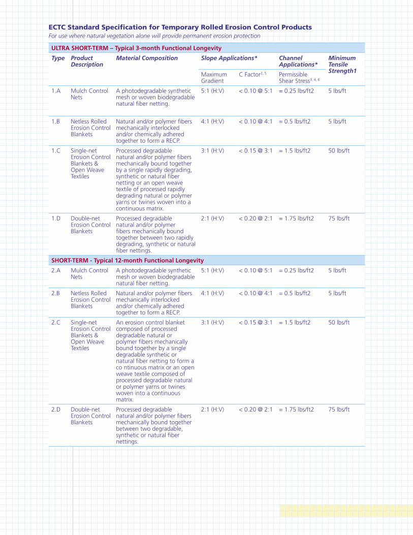
ECTC Standard Specification for Temporary Rolled Erosion Control ProductsFor use where natural vegetation alone will provide permanent erosion protection
ULTRA SHORT-TERM – Typical 3-month Functional Longevity
Type Product Description
Material Composition Slope Applications* Channel Applications*
Minimum Tensile Strength1
Maximum Gradient
C Factor2, 5 Permissible Shear Stress3, 4, 6
1.A Mulch Control Nets
A photodegradable synthetic mesh or woven biodegradable natural fiber netting.
5:1 (H:V) < 0.10 @ 5:1 = 0.25 lbs/ft2 5 lbs/ft
1.B Netless Rolled Erosion Control Blankets
Natural and/or polymer fibers mechanically interlocked and/or chemically adhered together to form a RECP.
4:1 (H:V) < 0.10 @ 4:1 = 0.5 lbs/ft2 5 lbs/ft
1.C Single-net Erosion Control Blankets & Open Weave Textiles
Processed degradable natural and/or polymer fibers mechanically bound together by a single rapidly degrading, synthetic or natural fiber netting or an open weave textile of processed rapidly degrading natural or polymer yarns or twines woven into a continuous matrix.
3:1 (H:V) < 0.15 @ 3:1 = 1.5 lbs/ft2 50 lbs/ft
1.D Double-net Erosion Control Blankets
Processed degradable natural and/or polymer fibers mechanically bound together between two rapidly degrading, synthetic or natural fiber nettings.
2:1 (H:V) < 0.20 @ 2:1 = 1.75 lbs/ft2 75 lbs/ft
SHORT-TERM - Typical 12-month Functional Longevity
2.A Mulch Control Nets
A photodegradable synthetic mesh or woven biodegradable natural fiber netting.
5:1 (H:V) < 0.10 @ 5:1 = 0.25 lbs/ft2 5 lbs/ft
2.B Netless Rolled Erosion Control Blankets
Natural and/or polymer fibers mechanically interlocked and/or chemically adhered together to form a RECP.
4:1 (H:V) < 0.10 @ 4:1 = 0.5 lbs/ft2 5 lbs/ft
2.C Single-net Erosion Control Blankets & Open Weave Textiles
An erosion control blanket composed of processed degradable natural or polymer fibers mechanically bound together by a single degradable synthetic or natural fiber netting to form a co ntinuous matrix or an open weave textile composed of processed degradable natural or polymer yarns or twines woven into a continuous matrix.
3:1 (H:V) < 0.15 @ 3:1 = 1.5 lbs/ft2 50 lbs/ft
2.D Double-net Erosion Control Blankets
Processed degradable natural and/or polymer fibers mechanically bound together between two degradable, synthetic or natural fiber nettings.
2:1 (H:V) < 0.20 @ 2:1 = 1.75 lbs/ft2 75 lbs/ft
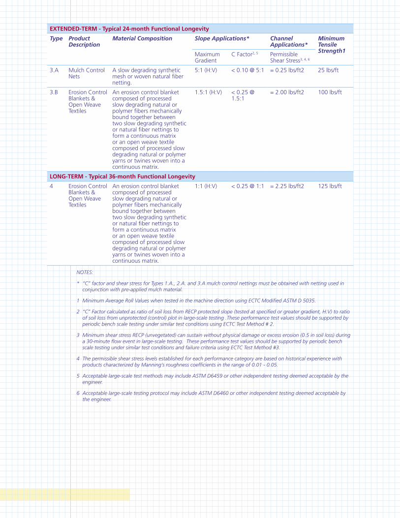
EXTENDED-TERM - Typical 24-month Functional Longevity
Type Product Description
Material Composition Slope Applications* Channel Applications*
Minimum Tensile Strength1
Maximum Gradient
C Factor2, 5 Permissible Shear Stress3, 4, 6
3.A Mulch Control Nets
A slow degrading synthetic mesh or woven natural fiber netting.
5:1 (H:V) < 0.10 @ 5:1 = 0.25 lbs/ft2 25 lbs/ft
3.B Erosion Control Blankets & Open Weave Textiles
An erosion control blanket composed of processed slow degrading natural or polymer fibers mechanically bound together between two slow degrading synthetic or natural fiber nettings to form a continuous matrix or an open weave textile composed of processed slow degrading natural or polymer yarns or twines woven into a continuous matrix.
1.5:1 (H:V) < 0.25 @ 1.5:1
= 2.00 lbs/ft2 100 lbs/ft
LONG-TERM - Typical 36-month Functional Longevity
4 Erosion Control Blankets & Open Weave Textiles
An erosion control blanket composed of processed slow degrading natural or polymer fibers mechanically bound together between two slow degrading synthetic or natural fiber nettings to form a continuous matrix or an open weave textile composed of processed slow degrading natural or polymer yarns or twines woven into a continuous matrix.
1:1 (H:V) < 0.25 @ 1:1 = 2.25 lbs/ft2 125 lbs/ft
NOTES:
* “C” factor and shear stress for Types 1.A., 2.A. and 3.A mulch control nettings must be obtained with netting used in conjunction with pre-applied mulch material.
1 Minimum Average Roll Values when tested in the machine direction using ECTC Modified ASTM D 5035.
2 “C” Factor calculated as ratio of soil loss from RECP protected slope (tested at specified or greater gradient, H:V) to ratio of soil loss from unprotected (control) plot in large-scale testing .These performance test values should be supported by periodic bench scale testing under similar test conditions using ECTC Test Method # 2.
3 Minimum shear stress RECP (unvegetated) can sustain without physical damage or excess erosion (0.5 in soil loss) during a 30-minute flow event in large-scale testing. These performance test values should be supported by periodic bench scale testing under similar test conditions and failure criteria using ECTC Test Method #3.
4 The permissible shear stress levels established for each performance category are based on historical experience with products characterized by Manning’s roughness coefficients in the range of 0.01 - 0.05.
5 Acceptable large-scale test methods may include ASTM D6459 or other independent testing deemed acceptable by the engineer.
6 Acceptable large-scale testing protocol may include ASTM D6460 or other independent testing deemed acceptable by the engineer.
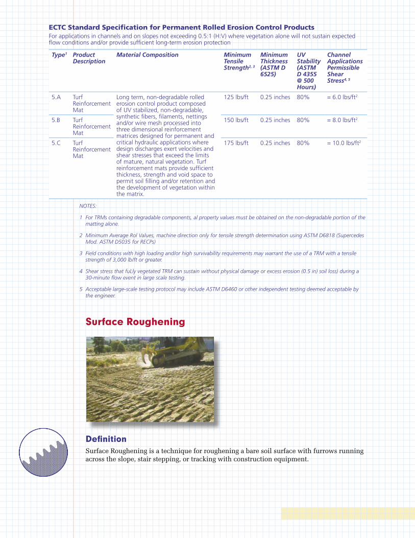
ECTC Standard Specifi cation for Permanent Rolled Erosion Control ProductsFor applications in channels and on slopes not exceeding 0.5:1 (H:V) where vegetation alone will not sustain expected fl ow conditions and/or provide suffi cient long-term erosion protection
Type1 Product Description
Material Composition Minimum Tensile Strength2, 3
Minimum Thickness (ASTM D 6525)
UV Stability (ASTM D 4355 @ 500 Hours)
Channel Applications Permissible Shear Stress4, 5
5.A Turf Reinforcement Mat
Long term, non-degradable rolled erosion control product composed of UV stabilized, non-degradable, synthetic fi bers, fi laments, nettings and/or wire mesh processed into three dimensional reinforcement matrices designed for permanent and critical hydraulic applications where design discharges exert velocities and shear stresses that exceed the limits of mature, natural vegetation. Turf reinforcement mats provide suffi cient thickness, strength and void space to permit soil fi lling and/or retention and the development of vegetation within the matrix.
125 lbs/ft 0.25 inches 80% = 6.0 lbs/ft2
5.B Turf Reinforcement Mat
150 lbs/ft 0.25 inches 80% = 8.0 lbs/ft2
5.C Turf Reinforcement Mat
175 lbs/ft 0.25 inches 80% = 10.0 lbs/ft2
NOTES:
1 For TRMs containing degradable components, al property values must be obtained on the non-degradable portion of the matting alone.
2 Minimum Average Rol Values, machine direction only for tensile strength determination using ASTM D6818 (Supercedes Mod. ASTM D5035 for RECPs)
3 Field conditions with high loading and/or high survivability requirements may warrant the use of a TRM with a tensile strength of 3,000 lb/ft or greater.
4 Shear stress that fuLly vegetated TRM can sustain without physical damage or excess erosion (0.5 in) soil loss) during a 30-minute fl ow event in large scale testing.
5 Acceptable large-scale testing protocol may include ASTM D6460 or other independent testing deemed acceptable by the engineer.
Surface Roughening
Defi nitionSurface Roughening is a technique for roughening a bare soil surface with furrows running across the slope, stair stepping, or tracking with construction equipment.
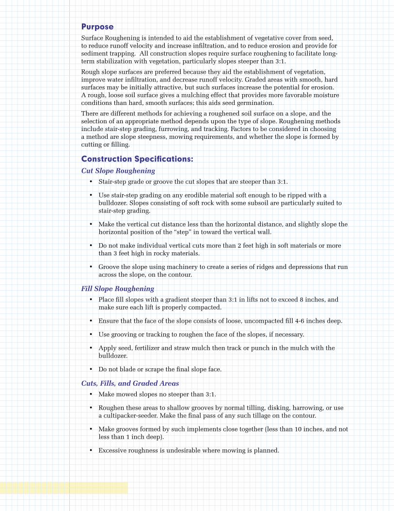
PurposeSurface Roughening is intended to aid the establishment of vegetative cover from seed, to reduce runoff velocity and increase infiltration, and to reduce erosion and provide for sediment trapping. All construction slopes require surface roughening to facilitate long-term stabilization with vegetation, particularly slopes steeper than 3:1.
Rough slope surfaces are preferred because they aid the establishment of vegetation, improve water infiltration, and decrease runoff velocity. Graded areas with smooth, hard surfaces may be initially attractive, but such surfaces increase the potential for erosion. A rough, loose soil surface gives a mulching effect that provides more favorable moisture conditions than hard, smooth surfaces; this aids seed germination.
There are different methods for achieving a roughened soil surface on a slope, and the selection of an appropriate method depends upon the type of slope. Roughening methods include stair-step grading, furrowing, and tracking. Factors to be considered in choosing a method are slope steepness, mowing requirements, and whether the slope is formed by cutting or filling.
Construction Specifications: Cut Slope Roughening
• Stair-step grade or groove the cut slopes that are steeper than 3:1.
• Use stair-step grading on any erodible material soft enough to be ripped with a bulldozer. Slopes consisting of soft rock with some subsoil are particularly suited to stair-step grading.
• Make the vertical cut distance less than the horizontal distance, and slightly slope the horizontal position of the “step” in toward the vertical wall.
• Do not make individual vertical cuts more than 2 feet high in soft materials or more than 3 feet high in rocky materials.
• Groove the slope using machinery to create a series of ridges and depressions that run across the slope, on the contour.
Fill Slope Roughening
• Place fill slopes with a gradient steeper than 3:1 in lifts not to exceed 8 inches, and make sure each lift is properly compacted.
• Ensure that the face of the slope consists of loose, uncompacted fill 4-6 inches deep.
• Use grooving or tracking to roughen the face of the slopes, if necessary.
• Apply seed, fertilizer and straw mulch then track or punch in the mulch with the bulldozer.
• Do not blade or scrape the final slope face.
Cuts, Fills, and Graded Areas
• Make mowed slopes no steeper than 3:1.
• Roughen these areas to shallow grooves by normal tilling, disking, harrowing, or use a cultipacker-seeder. Make the final pass of any such tillage on the contour.
• Make grooves formed by such implements close together (less than 10 inches, and not less than 1 inch deep).
• Excessive roughness is undesirable where mowing is planned.

Roughening With Tracked Machinery
• Limit roughening with tracked machinery to soils with a sandy textural component to avoid undue compaction of the soil surface.
• Operate tracked machinery up and down the slope to leave horizontal depressions in the soil. Do not back-blade during the fi nal grading operation.
Immediately seed and mulch roughened areas to obtain optimum seed germination and growth.
Inspection and MaintenancePeriodically check the seeded slopes for rills and washes. Fill these areas slightly above the original grade, then reseed and mulch as soon as possible.
Slope Drain
Defi nitionA slope drain is a pipe or lined (rock or concrete) channel extending from the top to the bottom of a cut or fi ll slope.
PurposeTo convey concentrated runoff down the face of a cut or fi ll slope without causing erosion. Temporary slope drains are generally used in conjunction with diversions to convey runoff down a slope until permanent water disposal measures can be installed.
Design Criteria General
It is very important that these temporary structures be sized, installed, and maintained properly, because their failure will usually result in severe erosion of the slope.
The entrance section to the drain should be well-entrenched and stable so that surface water can enter freely. The drain should extend downslope beyond the toe of the slope to a stable area or appropriately stabilized outlet.
Pipe Capacity
Peak fl ow from the 10-year 24-hour storm.
Conduit
Construct slope drain pipes from heavy-duty, fl exible materials such as non-perforated, corrugated plastic pipe, or open top overside drains with tapered inlets, or CMP. Install
reinforced, hold-down grommets or stakes to anchor the conduit at intervals not to exceed 10 feet with the outlet end securely fastened in place. CMP or corrugated plastic pipe must have one anchor assembly for every 20 feet of slope drain. The conduit must extend beyond the toe of the slope.
Entrance
Construct the entrance to the slope drain of a standard flared-inlet section of pipe with a minimum 6-inch metal toe plate. Make all fittings watertight. A standard T-section fitting may also be used at the inlet. An open top flared inlet for overside drain may also be used.
Temporary Diversion
Generally, use an earthen diversion with a dike ridge or berm to direct surface runoff into the temporary slope drain. Make the height of the ridge over the drain conduit a minimum of 1.5 feet and at least 6 inches higher than the adjoining ridge on either side. The lowest point of the diversion ridge should be a minimum of 1 foot above the top of the drain so that design flow can freely enter the pipe.
Outlet Protection
Protect the outlet of the slope drain from erosion with an energy dissipator.
Construction SpecificationsA common failure of slope drains is caused by water saturating the soil and seeping along the pipe. Proper backfilling around and under the pipe haunches with stable soil material and hand compacting in 6 inch lifts to achieve firm contact between the pipe and the soil at all points will reduce this type of failure.
• Place slope drains on undisturbed soil or well-compacted fill at locations and elevations shown on the plans.
• Slightly slope the section of pipe under the dike toward its outlet.
• Compact the soil under and around the entrance section in lifts not to exceed 6 inches.
• Ensure that fill over the drain at the top of the slope has a minimum depth of 1.5 feet and a minimum top width of 4 feet. The sides should have a 3:1 slope.
• Ensure that all slope drain connections are watertight.
• Ensure that all fill material is well-compacted. Securely fasten the exposed section of the drain with grommets or stakes spaced no more than 10 feet apart.
• Extend the drain beyond the toe of the slope and adequately protect the outlet from erosion.
• Make the settled, compacted dike ridge no less than 1 foot higher than the top of the pipe inlet.
• Immediately stabilize all disturbed areas following construction.
Inspection and MaintenanceInspect the slope drain and supporting diversions after every significant rainfall and promptly make necessary repairs. When the protected area has been permanently stabilized, temporary measures may be removed, materials disposed of properly, and all disturbed areas stabilized appropriately.

Gabion
Defi nitionRectangular wire baskets fi lled with stones used as pervious, semi-fl exible building blocks. Live rooting branches may be placed between the rock-fi lled baskets.
PurposeTo protect streambanks from the erosive forces of moving water. Rock-fi lled gabions can be used to armor the bed and/or banks of channels or used to divert fl ow away from eroding channel sections.
Rock-fi lled or vegetated rock gabions are applicable to streambank sections which are subject to excessive erosion due to increased fl ows or disturbance during construction. This practice is applicable where fl ow velocities exceed 6 ft/sec and where vegetative streambank protection alone is not suffi cient.
Gabions can be used to construct defl ectors or groins intended to divert fl ow away from eroding streambank sections. Gabions are also used to construct retaining walls and grade control structures.
Types of Gabion Structures Gabion Wall
Basically a gravity wall that relies on its own weight and frictional resistance to resist sliding and overturning from lateral earth pressure.
Vegetated Rock Gabion
A rock-fi lled gabion earth-retaining structure which has live branches placed between each consecutive layer of rock-fi lled baskets. The live branches will take root inside the gabion and into the soil behind the structure. The vegetation will consolidate the structures and bind it to the slope.
Gabion Defl ector
Defl ector or groins project into the streams and divert fl ows away from eroding streambank sections.
Gabion Aprons
Rock fi lled gabions or gabion mattress used as outlet protection, energy dissipators or spillways. These semi-fl exible gabions are designed to settle without fracture and adhere to the ground if scour occurs.
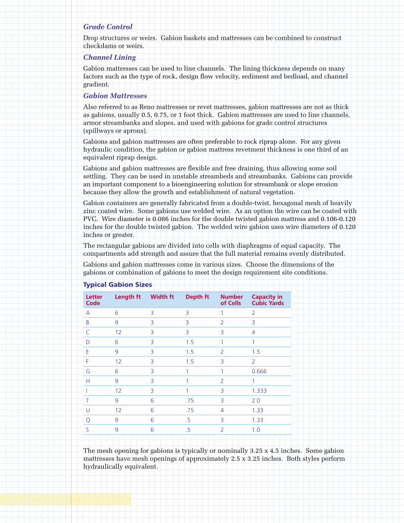
Grade Control
Drop structures or weirs. Gabion baskets and mattresses can be combined to construct checkdams or weirs.
Channel Lining
Gabion mattresses can be used to line channels. The lining thickness depends on many factors such as the type of rock, design flow velocity, sediment and bedload, and channel gradient.
Gabion Mattresses
Also referred to as Reno mattresses or revet mattresses, gabion mattresses are not as thick as gabions, usually 0.5, 0.75, or 1 foot thick. Gabion mattresses are used to line channels, armor streambanks and slopes, and used with gabions for grade control structures (spillways or aprons).
Gabions and gabion mattresses are often preferable to rock riprap alone. For any given hydraulic condition, the gabion or gabion mattress revetment thickness is one third of an equivalent riprap design.
Gabions and gabion mattresses are flexible and free draining, thus allowing some soil settling. They can be used in unstable streambeds and streambanks. Gabions can provide an important component to a bioengineering solution for streambank or slope erosion because they allow the growth and establishment of natural vegetation.
Gabion containers are generally fabricated from a double-twist, hexagonal mesh of heavily zinc coated wire. Some gabions use welded wire. As an option the wire can be coated with PVC. Wire diameter is 0.086 inches for the double twisted gabion mattress and 0.106-0.120 inches for the double twisted gabion. The welded wire gabion uses wire diameters of 0.120 inches or greater.
The rectangular gabions are divided into cells with diaphragms of equal capacity. The compartments add strength and assure that the full material remains evenly distributed.
Gabions and gabion mattresses come in various sizes. Choose the dimensions of the gabions or combination of gabions to meet the design requirement site conditions.
Typical Gabion Sizes
Letter Code
Length ft Width ft Depth ft Number of Cells
Capacity in Cubic Yards
A 6 3 3 1 2
B 9 3 3 2 3
C 12 3 3 3 4
D 6 3 1.5 1 1
E 9 3 1.5 2 1.5
F 12 3 1.5 3 2
G 6 3 1 1 0.666
H 9 3 1 2 1
I 12 3 1 3 1.333
T 9 6 .75 3 2.0
U 12 6 .75 4 1.33
Q 9 6 .5 3 1.33
S 9 6 .5 2 1.0
The mesh opening for gabions is typically or nominally 3.25 x 4.5 inches. Some gabion mattresses have mesh openings of approximately 2.5 x 3.25 inches. Both styles perform hydraulically equivalent.

Design CriteriaGabions should be designed and installed in accordance with manufacturer’s standards and specifications.
Gabion walls are appropriate where:
• The vertical integrity of a soil bank needs a higher tensile strength to reduce sloughing of the streambank.
• There is moderate to excessive sub-surface water movements that may be creating erosion and damaging other types of non permeable structures.
• An excessively steep stream bank must be stabilized and vegetative or extreme mechanical means of stabilization (i.e., pulling back bank) are not feasible due to site conditions.
• Where slope must be modified while heavy machinery is unavailable to the site.
• Fill must be disposed of along an eroding streambank (fill can be placed behind gabion to modify slope).
• A retaining or toe wall is needed to stabilize the slope.
• Rock riprap is an appropriate practice but the available or desired rock size (smaller) is not sufficient alone to resist the expected shear stress exerted on the revetment.
Construction Specifications • Install gabions in accordance with manufacturer’s standards and specifications.
• Gabions shall be fabricated in such a manner that the sides, ends, lid and diaphragms can be assembled at the construction site into rectangular baskets of the sizes specified and shown on the construction drawings.
• Gabions shall be of single-unit construction; the base, lid, ends and sides shall be either woven into a single unit or one edge of these members connected to the base section of the gabion in such a manner that the strength and flexibility at the connecting point is at least equal to that of the mesh.
• Where the length of the gabion exceeds 1.5 times its horizontal width, the gabion shall be divided by diaphragms of the same mesh and gauge as the body of the gabion, into cells whose length does not exceed the horizontal width.
• Gabions and mattresses are unfolded and assembled. Corners are first joined together and then the diaphragms are attached to the side panels.
• Each gabion shall be assembled by tying all untied edges with lacing wire or approved fasteners. The lacing wire shall be tightly looped around every other mesh opening along the seams in such a manner that single and double loops are alternated.
• The gabion or gabion mattress shall be securely keyed into the streambank or streambed to assure that flows do not erode the soils beneath or around it.
• Starting at the lowest point of the slope, excavate the loose material 2-3 feet below the ground elevation until a stable foundation is reached.
• Excavate the back of the stable foundation slightly deeper than the front so the foundation tilts back into the slope.
• A line of empty gabion units shall be placed in the bottom of its excavation and
the baskets are to be joined together along adjacent edges, both horizontally and vertically. The base of the empty gabions placed on top of a filled line of gabions shall be tightly wired to the latter at front and back.
• To achieve better alignment and finish in gabion walls, stretching of the gabions is recommended.
• For gabions greater than 18 inches, connecting wires (wires tied to opposite faces of each gabion cell) shall be installed during filling operations.
• Gabions shall be filled to a depth of 12 inches and then two connecting wires shall be tightly tied to opposite faces of each gabion cell at a height of 12 inches above the base. Gabions shall then be filled with a further depth of 12 inches and two connecting wires shall be similarly tied at this level. Then gabions shall be filled to the top.
• Fill gabions with appropriately sized river rock or quarry stone or other approved infill material. Use of hard material with high specific gravity is recommended. The tops of the gabions are then closed along edges and diaphragms using lacing wire or approved fasteners. Keep voids and bulges in the gabions to a minimum in order to ensure proper alignment and a neat, compact, square appearance.
• The stone size to fill gabions shall be 3-5 inches for gabion mattresses and 4-8 inches for gabions.
Inspection and MaintenanceAll structures should be maintained in an “as built” condition. Structural damage caused by storm events should be repaired as soon as possible to prevent further damage to the structure or erosion of the streambank.
Cellular Confinement Systems
DefinitionA three-dimensional, honeycomb earth-retaining structure used to mechanically stabilize the surface of earth and fill slopes.
PurposeCellular Confinement System (CCS) is a permanent erosion control practice intended to stabilize infill materials for slope and channel protection, load support, and earth retention applications. The expandable panels create a cellular system that confines topsoil infill, protects and reinforces the plant’s root zone, and permits natural subsurface drainage. The honeycomb shaped cells encapsulate and prevent erosion of the infill material. The cellular confinement systems are used for:
• Revetments - filling the cells with topsoil or rock can provide an alternative to hard armor revetment systems.
• Erosion control on steep slopes - cells can be infilled with soil and vegetated or infilled with granular materials. Slopes as steep as 1:1 can be treated with cellular confinement systems. Application on steep slopes may require tendons for system stability and security against sliding.
• Flexible channel lining systems, either vegetated or rock filled.
• Road stabilization - cells confine and reinforce select fill materials, thereby increasing load-bearing capacities. Creates a porous pavement system with aggregate or topsoil/vegetation infill.
• Temporary low-water stream crossings.
Construction SpecificationsSite Preparation
• The surface of the slope should be leveled, with stones and debris removed. Gullies should be filled and well compacted. Major obstacles such as boulders can be left in place. Simply cut out panel around them.
• Following excavation and fill placement operations, shape and compact the subgrade surfaces to the designed elevations and grades.
• Excavate the area so that when cellular confinement systems are installed, the top of the section is flush with or slightly lower than the adjacent terrain or final grade.
• Remove unstable subgrade soils when required and install geotextiles underlayer if specified.
Installation
• Anchor the cellular confinement system sections at the top of the slope across a 2-4 foot ledge. Expand and stretch the cellular confinement system down the slopes.
• Type of anchors and frequency of anchoring will depend on site conditions. Typically, every other cell across the top section is anchored with J-pins or other suitable anchor devices. This anchoring pattern is repeated every 6 feet down the slope.
• The cells should be anchored securely in order to prevent deformation of the panel while backfilling. Depending on the slope angle and fill soils involved, intermediate anchorage will be necessary on some interior cells in order to limit sideways deformation, insure stability and avoid overloading the upper sections.
• Additional panels are abutted together and joined with staples, hog rings or other suitable fasteners.
Infill Placement
• Place the fill material in the expanded cells with suitable equipment such as a back-hoe, front-end loader or conveyer.
• Limit drop height to 3 feet.
• On steep slopes, infill from the crest to the toe to prevent displacement and deformation of the cellular confinement system.
• Overfilling and compacting of infill depend on type and consistency of material and the depth of the cells.
Inspection and Maintenance • Inspect slope periodically and after significant rainstorms to check for erosion. Any
failure should be repaired immediately.
• If vegetation has not been established, fertilize and reseed damaged and sparse areas immediately.
Polyacrylamides
DefinitionThe land application or stormwater application of product containing anionic polyacrylamide (PAM).
PurposeLand application of PAM is performed to reduce soil surface erosion due to wind and/or water forces. Stormwater applications of PAM promote settling of fine soil particles in sediment basins.
Polyacrylamides have two general erosion and sediment control applications. One temporary practice is direct soil surface application to sites where the timely establishment of vegetation may not be feasible or where vegetative cover is absent or inadequate. Such areas may include construction sites where land-disturbing activities prevent the establishment or maintenance of a vegetative cover. The product may also be applied to stormwater as it enters sediment basins. This will cause soil particles to bind together and settle within the pond.
This temporary practice is not intended for application to surface waters of the state. It is intended for application within construction stormwater drainages that feed into pre-constructed sediment ponds or basins.
Anionic PAM is available in emulsions, powders, and gel bars or logs. It is required that other Best Management Practices be used in combination with anionic PAM. The use of seed and mulch for additional erosion protection beyond the life of the anionic PAM is recommended. Repeat application if disturbance occurs to target area.
Design CriteriaThe following recommendations relating to design may enhance the use of, or avoid problems with the practice:
1. Use 25-foot setbacks when applying anionic PAM near natural water bodies.
2. Consider that performance of PAM decreases with time and exposure to ultraviolet light.
3. In concentrated flow channels, the effectiveness of PAM decreases.
4. Mulch to protect seed if seed is applied with anionic PAM.
5. Never add water to PAM; add PAM slowly to water. If water is added to PAM, clumping can form which can clog dispensers. This signifies incomplete dissolving of the PAM and therefore increases the risk of under-application.
SpecificationsApplication rates should conform to manufacturer’s guidelines for application. Only the anionic form of PAM should be used. Cationic PAM is toxic and should NOT be used. PAM and PAM mixtures should be environmentally benign, harmless to fish, wildlife, and plants. PAM and PAM mixtures should be noncombustible.
Anionic PAM, in pure form, should have less than or equal to 0.05% acrylamide monomer by weight, as established by the Food and Drug Administration and the Environmental Protection Agency. To maintain less than or equal to 0.05% of acrylamide monomer, the maximum application rate of PAM, in pure form, should not exceed 200 pounds/acre/year. Do not over-apply PAM. Excessive application of PAM can lower infiltration rate or suspend solids in water rather than promoting settling.

Users of anionic PAM should obtain and follow all Material Safety Data Sheet requirements and manufacturer’s recommendations. Additives to PAM such as fertilizers, solubility promoters, or inhibitors, should be nontoxic. The manufacturer or supplier should provide written application methods of PAM and PAM mixtures. The application method should ensure uniform coverage to the target and avoid drift to non-target areas including waters of the state. The manufacturer or supplier should also provide written instructions to ensure proper safety, storage, and mixing of the product.
Gel bars or logs of anionic PAM mixtures may be used in ditch systems. This application should meet the same testing requirement as anionic PAM emulsions and powders.
To prevent exceeding the acrylamide monomer limit in the event of a spill, the anionic PAM in pure form should not exceed 200 pounds/batch at 0.05% acrylamide monomer (AMD) or 400 pounds/batch at 0.025% AMD.
Inspection and MaintenanceInspections should be made before anticipated storm events (or series of storm events such as intermittent showers over one or more days) and within 24 hours after the end of a rainfall event of 0.5 inches or greater, and at least once every 14 calendar days. Maintenance needs identified in inspections or by other means shall be accomplished before the next storm event if possible, but in no case more than seven days after the need is identified. Maintenance will consist of reapplying anionic PAM to disturbed areas including high use traffic areas that interfere in the performance of this practice.

Inlets, Pipes, and Culverts
Curb Inlet Sediment Barrier
Defi nitionCurb inlet sediment barriers are temporary barriers constructed from concrete block and gravel or gravel fi lled sandbags.
PurposeCurb inlet sediment barriers are intended to reduce the sediment discharged into storm drains by ponding the runoff and allowing the sediment to settle out. The structures allow for overfl ow from high runoff events and the gravel allows the area to dewater rapidly.
Design CriteriaThere is no formal design. The sediment barriers can be used at curb inlets on gently sloping, paved streets where:
• water can pond and allow sediment to separate out of suspension;
• runoff is relatively low, less than 0.5 ft3/sec
Once the small catchment areas behind the sandbags or block and gravel fi ll with sediment, future sediment-laden runoff will enter the storm drain without being desilted. Therefore, sediment must be removed from these structures during or after each storm. Additional storage can be obtained by constructing a series of sandbag barriers along the gutter so that each barrier traps small amounts of sediment.
Construction Specifi cationsGeneral
• Place the barriers on gently sloping streets where water can pond.
• The barriers must allow for overfl ow from a severe storm event. Slope runoff shall be allowed to fl ow over blocks and gravel and not be bypassed over the curb. A spillway shall be constructed with the sandbag structures to allow overfl ow.
• The sandbag should be of woven-type geotextile fabric since burlap bags deteriorate rapidly.
• The sandbags shall be fi lled with 3/4 inch drain rock or 1/4 inch pea gravel.
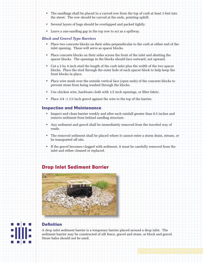
• The sandbags shall be placed in a curved row from the top of curb at least 3 feet into the street. The row should be curved at the ends, pointing uphill.
• Several layers of bags should be overlapped and packed tightly.
• Leave a one-sandbag gap in the top row to act as a spillway.
Block and Gravel Type Barriers
• Place two concrete blocks on their sides perpendicular to the curb at either end of the inlet opening. These will serve as spacer blocks.
• Place concrete blocks on their sides across the front of the inlet and abutting the spacer blocks. The openings in the blocks should face outward, not upward.
• Cut a 2 by 4 inch stud the length of the curb inlet plus the width of the two spacer blocks. Place the stud through the outer hole of each spacer block to help keep the front blocks in place.
• Place wire mesh over the outside vertical face (open ends) of the concrete blocks to prevent stone from being washed through the blocks.
• Use chicken wire, hardware cloth with 1/2 inch openings, or fi lter fabric.
• Place 3/4 -1 1/3 inch gravel against the wire to the top of the barrier.
Inspection and Maintenance • Inspect and clean barrier weekly and after each rainfall greater than 0.5 inches and
remove sediment from behind sandbag structure.
• Any sediment and gravel shall be immediately removed from the traveled way of roads.
• The removed sediment shall be placed where it cannot enter a storm drain, stream, or be transported off site.
• If the gravel becomes clogged with sediment, it must be carefully removed from the inlet and either cleaned or replaced.
Drop Inlet Sediment Barrier
Defi nitionA drop inlet sediment barrier is a temporary barrier placed around a drop inlet. The sediment barrier may be constructed of silt fence, gravel and stone, or block and gravel. Straw bales should not be used.
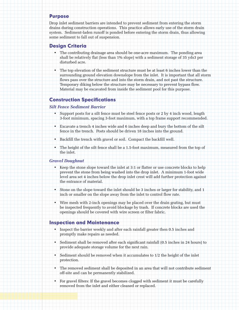
PurposeDrop inlet sediment barriers are intended to prevent sediment from entering the storm drains during construction operations. This practice allows early use of the storm drain system. Sediment-laden runoff is ponded before entering the storm drain, thus allowing some sediment to fall out of suspension.
Design Criteria • The contributing drainage area should be one-acre maximum. The ponding area
shall be relatively flat (less than 1% slope) with a sediment storage of 35 yds3 per disturbed acre.
• The top elevation of the sediment structure must be at least 6 inches lower than the surrounding ground elevation downslope from the inlet. It is important that all storm flows pass over the structure and into the storm drain, and not past the structure. Temporary diking below the structure may be necessary to prevent bypass flow. Material may be excavated from inside the sediment pool for this purpose.
Construction SpecificationsSilt Fence Sediment Barrier
• Support posts for a silt fence must be steel fence posts or 2 by 4 inch wood, length 3-foot minimum, spacing 3-foot maximum, with a top frame support recommended.
• Excavate a trench 4 inches wide and 6 inches deep and bury the bottom of the silt fence in the trench. Posts should be driven 18 inches into the ground.
• Backfill the trench with gravel or soil. Compact the backfill well.
• The height of the silt fence shall be a 1.5-foot maximum, measured from the top of the inlet.
Gravel Doughnut
• Keep the stone slope toward the inlet at 3:1 or flatter or use concrete blocks to help prevent the stone from being washed into the drop inlet. A minimum 1-foot wide level area set 4 inches below the drop inlet crest will add further protection against the entrance of material.
• Stone on the slope toward the inlet should be 3 inches or larger for stability, and 1 inch or smaller on the slope away from the inlet to control flow rate.
• Wire mesh with 2-inch openings may be placed over the drain grating, but must be inspected frequently to avoid blockage by trash. If concrete blocks are used the openings should be covered with wire screen or filter fabric.
Inspection and Maintenance • Inspect the barrier weekly and after each rainfall greater then 0.5 inches and
promptly make repairs as needed.
• Sediment shall be removed after each significant rainfall (0.5 inches in 24 hours) to provide adequate storage volume for the next rain.
• Sediment should be removed when it accumulates to 1/2 the height of the inlet protection.
• The removed sediment shall be deposited in an area that will not contribute sediment off-site and can be permanently stabilized.
• For gravel filters: If the gravel becomes clogged with sediment it must be carefully removed from the inlet and either cleaned or replaced.
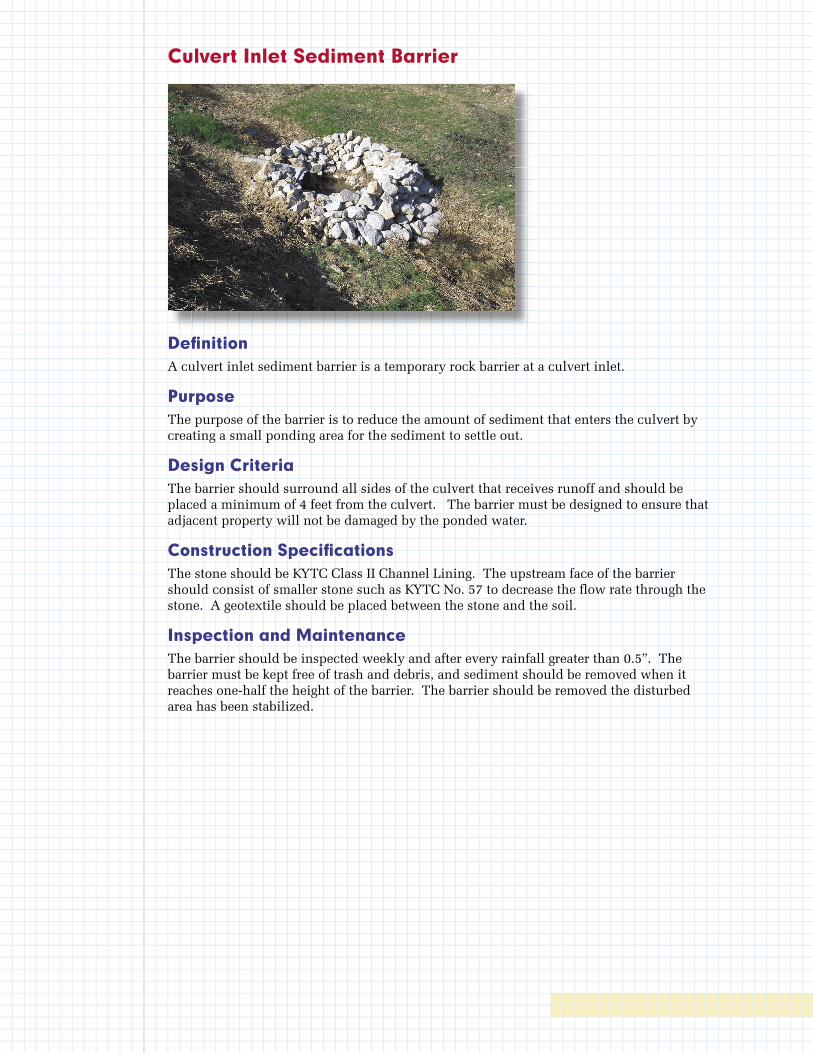
Culvert Inlet Sediment Barrier
Defi nitionA culvert inlet sediment barrier is a temporary rock barrier at a culvert inlet.
PurposeThe purpose of the barrier is to reduce the amount of sediment that enters the culvert by creating a small ponding area for the sediment to settle out.
Design CriteriaThe barrier should surround all sides of the culvert that receives runoff and should be placed a minimum of 4 feet from the culvert. The barrier must be designed to ensure that adjacent property will not be damaged by the ponded water.
Construction Specifi cationsThe stone should be KYTC Class II Channel Lining. The upstream face of the barrier should consist of smaller stone such as KYTC No. 57 to decrease the fl ow rate through the stone. A geotextile should be placed between the stone and the soil.
Inspection and MaintenanceThe barrier should be inspected weekly and after every rainfall greater than 0.5”. The barrier must be kept free of trash and debris, and sediment should be removed when it reaches one-half the height of the barrier. The barrier should be removed the disturbed area has been stabilized.
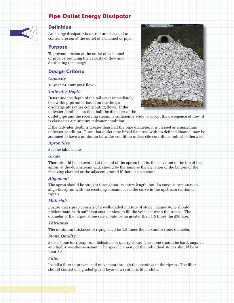
Pipe Outlet Energy Dissipator
Defi nitionAn energy dissipator is a structure designed to control erosion at the outlet of a channel or pipe.
PurposeTo prevent erosion at the outlet of a channel or pipe by reducing the velocity of fl ow and dissipating the energy.
Design CriteriaCapacity
10-year 24-hour peak fl ow
Tailwater Depth
Determine the depth of the tailwater immediately below the pipe outlet based on the design discharge plus other contributing fl ows. If the tailwater depth is less than half the diameter of the outlet pipe and the receiving stream is suffi ciently wide to accept the divergence of fl ow, it is classed as a minimum tailwater condition.
If the tailwater depth is greater than half the pipe diameter, it is classed as a maximum tailwater condition. Pipes that outlet onto broad fl at areas with no defi ned channel may be assumed to have a minimum tailwater condition unless site conditions indicate otherwise.
Apron Size
See the table below.
Grade
There should be no overfall at the end of the apron; that is, the elevation of the top of the apron, at the downstream end, should be the same as the elevation of the bottom of the receiving channel or the adjacent ground if there is no channel.
Alignment
The apron should be straight throughout its entire length, but if a curve is necessary to align the apron with the receiving stream, locate the curve in the upstream section of riprap.
Materials
Ensure that riprap consists of a well-graded mixture of stone. Larger stone should predominate, with suffi cient smaller sizes to fi ll the voids between the stones. The diameter of the largest stone size should be no greater than 1.5 times the d50 size.
Thickness
The minimum thickness of riprap shall be 1.5 times the maximum stone diameter.
Stone Quality
Select stone for riprap from fi eldstone or quarry stone. The stone should be hard, angular, and highly weather-resistant. The specifi c gravity of the individual stones should be at least 2.5.
Filter
Install a fi lter to prevent soil movement through the openings in the riprap. The fi lter should consist of a graded gravel layer or a synthetic fi lter cloth.
Construction Specifications • Ensure that the subgrade for the filter and riprap follows the required lines and
grades shown in the plan. Compact any fill required in the subgrade to the density of the surrounding undisturbed material. Low areas in the subgrade on undisturbed soil may also be filled by increasing the riprap thickness.
• The riprap and gravel filter must conform to the specified grading limits shown on the plans.
• Filter cloth, when used, must meet design requirements and be properly protected from punching or tearing during installation. Repair any damaged fabric by removing the riprap and placing another piece of filter cloth over the damaged area.
• All connecting joints should overlap a minimum of 1 foot. If the damage is extensive, replace the entire filter cloth.
• Riprap may be placed by equipment, but take care to avoid damaging the filter.
• The minimum thickness of the riprap should be 1.5 times the maximum stone diameter.
• Riprap may be field stone or rough quarry stone. It should be hard, angular, highly weather-resistant and well graded.
• Construct the apron with no overfall at the end. Make the top of the riprap at the downstream end level with the receiving area or slightly below it.
• Ensure that the apron is properly aligned with the receiving stream and preferably straight throughout its length. If a curve is needed to fit site conditions, place it in the upper section of the apron.
• Immediately after construction, stabilize all disturbed areas with vegetation.
Inspection and MaintenanceInspect riprap outlet structures weekly and after every rainfall greater than 0.5 inches to see if any erosion around or below the riprap has taken place or if stones have been dislodged. Immediately make all needed repairs to prevent further damage.

Table of Riprap Apron Dimensions
The tables below can be used to determine the length, width, and D50 stone size of a riprap apron based on circular culverts flowing full.
Riprap Aprons for Low Tailwater(downstream flow depth < 0.5 x pipe diameter)
Culvert Diameter
Lowest Value Intermediate Values to Interpolate From Highest Value
Q LA D50 Q LA D50 Q LA D50 Q LA D50 Q LA D50
Cfs Ft In Cfs Ft In Cfs Ft In Cfs Ft In Cfs Ft In
12” 4 7 6 6 10 6 9 13 6 12 16 7 14 17 8.5
15” 6.5 8 6 10 12 6 15 16 7 20 18 10 25 20 12
18” 10 9 6 15 14 6 20 17 7 30 22 11 40 25 14
21” 15 11 6 25 18 7 35 22 10 45 26 13 60 29 18
24” 21 13 6 35 20 8.5 50 26 12 65 30 16 80 33 19
27” 27 14 6 50 24 9.5 70 29 14 90 34 18 110 37 22
30” 36 16 6 60 25 9.5 90 33 15.5 120 38 20 140 41 24
36” 56 20 7 100 32 13 140 40 18 180 45 23 220 50 28
42” 82 22 8.5 120 32 12 160 39 17 200 45 20 260 52 26
48” 120 26 10 170 37 14 220 46 19 270 54 23 320 64 37
Source: Knoxville Engineering Department LA = Apron Length Apron Width = LA+ Culvert Diameter
Riprap Aprons for High Tailwater(downstream flow depth > 0.5 x pipe diameter)
Culvert Diameter
Lowest Value Intermediate Values to Interpolate From Highest Value
Q LA D50 Q LA D50 Q LA D50 Q LA D50 Q LA D50
Cfs Ft In Cfs Ft In Cfs Ft In Cfs Ft In Cfs Ft In
12” 4 8 6 6 18 6 9 28 6 12 36 7 14 40 8
15” 7 8 6 10 20 6 15 34 6 20 42 7.5 25 50 10
18” 10 8 6 15 22 6 20 34 6 30 50 9 40 60 11
21” 15 8 6 25 32 6 35 48 7 45 58 11 60 72 14
24” 20 8 6 35 36 6 50 55 8.5 65 68 12 80 80 15
27” 27 10 6 50 41 6 70 58 10 90 70 14 110 82 17
30” 36 11 6 60 42 6 90 64 11 120 80 15 140 90 18
36” 56 13 6 100 60 7 140 85 13 180 104 18 220 120 23
42” 82 15 6 120 50 6 160 75 10 200 96 14 260 120 19
48” 120 20 6 170 58 7 220 85 12 270 105 16 320 120 20
Source: Knoxville Engineering Department LA = Apron Length Apron Width = 0.4 LA+ Culvert Diameter
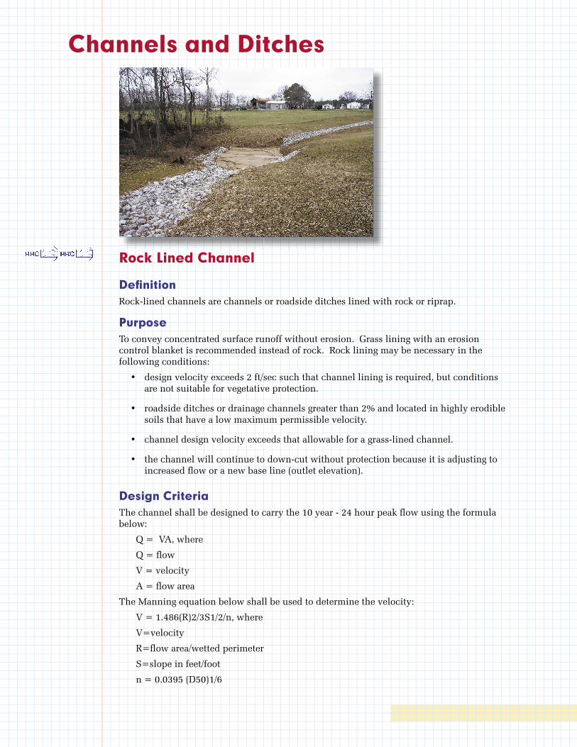
Channels and Ditches
Rock Lined Channel
Defi nitionRock-lined channels are channels or roadside ditches lined with rock or riprap.
PurposeTo convey concentrated surface runoff without erosion. Grass lining with an erosion control blanket is recommended instead of rock. Rock lining may be necessary in the following conditions:
• design velocity exceeds 2 ft/sec such that channel lining is required, but conditions are not suitable for vegetative protection.
• roadside ditches or drainage channels greater than 2% and located in highly erodible soils that have a low maximum permissible velocity.
• channel design velocity exceeds that allowable for a grass-lined channel.
• the channel will continue to down-cut without protection because it is adjusting to increased fl ow or a new base line (outlet elevation).
Design CriteriaThe channel shall be designed to carry the 10 year - 24 hour peak fl ow using the formula below:
Q = VA, where
Q = fl ow
V = velocity
A = fl ow area
The Manning equation below shall be used to determine the velocity:
V = 1.486(R)2/3S1/2/n, where
V=velocity
R=fl ow area/wetted perimeter
S=slope in feet/foot
n = 0.0395 (D50)1/6
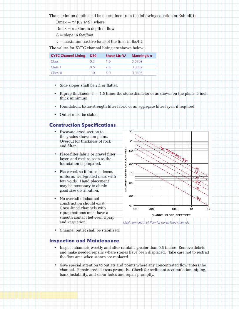
The maximum depth shall be determined from the following equation or Exhibit 1:
Dmax = τ / (62.4*S), where
Dmax = maximum depth of flow
S = slope in feet/foot
τ = maximum tractive force of the liner in lbs/ft2
The values for KYTC channel lining are shown below:
KYTC Channel Lining D50 Shear Lb/ft.2 Manning’s n
Class I 0.2 1.0 0.0302
Class II 0.5 2.5 0.0352
Class III 1.0 5.0 0.0395
• Side slopes shall be 2:1 or flatter.
• Riprap thickness: T = 1.5 times the stone diameter or as shown on the plans; 6 inch thick minimum.
• Foundation: Extra-strength filter fabric or an aggregate filter layer, if required.
• Outlet must be stable.
Construction Specifications • Excavate cross section to
the grades shown on plans. Overcut for thickness of rock and filter.
• Place filter fabric or gravel filter layer, and rock as soon as the foundation is prepared.
• Place rock so it forms a dense, uniform, well-graded mass with few voids. Hand placement may be necessary to obtain good size distribution.
• No overfall of channel construction should exist. Grass-lined channels with riprap bottoms must have a smooth contact between riprap and vegetation.
• Channel outlet shall be stabilized.
Inspection and Maintenance • Inspect channels weekly and after rainfalls greater than 0.5 inches Remove debris
and make needed repairs where stones have been displaced. Take care not to restrict the flow area when stones are replaced.
• Give special attention to outlets and points where any concentrated flow enters the channel. Repair eroded areas promptly. Check for sediment accumulation, piping, bank instability, and scour holes and repair promptly.
Maximum depth of flow for riprap lined channels
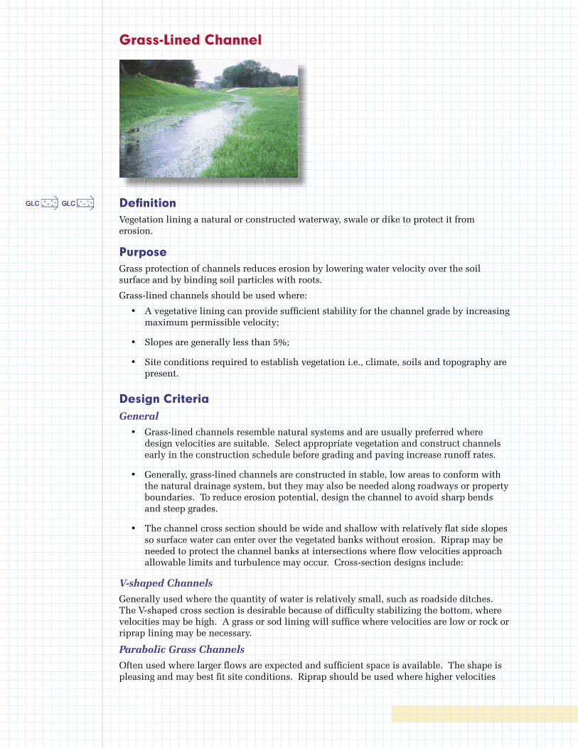
Grass-Lined Channel
Defi nitionVegetation lining a natural or constructed waterway, swale or dike to protect it from erosion.
PurposeGrass protection of channels reduces erosion by lowering water velocity over the soil surface and by binding soil particles with roots.
Grass-lined channels should be used where:
• A vegetative lining can provide suffi cient stability for the channel grade by increasing maximum permissible velocity;
• Slopes are generally less than 5%;
• Site conditions required to establish vegetation i.e., climate, soils and topography are present.
Design CriteriaGeneral
• Grass-lined channels resemble natural systems and are usually preferred where design velocities are suitable. Select appropriate vegetation and construct channels early in the construction schedule before grading and paving increase runoff rates.
• Generally, grass-lined channels are constructed in stable, low areas to conform with the natural drainage system, but they may also be needed along roadways or property boundaries. To reduce erosion potential, design the channel to avoid sharp bends and steep grades.
• The channel cross section should be wide and shallow with relatively fl at side slopes so surface water can enter over the vegetated banks without erosion. Riprap may be needed to protect the channel banks at intersections where fl ow velocities approach allowable limits and turbulence may occur. Cross-section designs include:
V-shaped Channels
Generally used where the quantity of water is relatively small, such as roadside ditches. The V-shaped cross section is desirable because of diffi culty stabilizing the bottom, where velocities may be high. A grass or sod lining will suffi ce where velocities are low or rock or riprap lining may be necessary.
Parabolic Grass Channels
Often used where larger fl ows are expected and suffi cient space is available. The shape is pleasing and may best fi t site conditions. Riprap should be used where higher velocities
are expected and where some dissipation of energy (velocity) is desired. Combinations of grass with riprap centers or turf reinforcement mat centers are useful where there is a continuous low flow in the channel.
Trapezoidal Grass Channels
Used where runoff volumes are large and slope is low so that velocities are non-erosive to vegetated linings. Trapezoidal channels generally have concrete or riprap lined center for low flow.
• Grass-lined channels must not be subject to sedimentation from disturbed areas.
• An established grass-lined channel resembles natural drainage systems and is usually preferred if design velocities are below 5 ft/sec.
• Channels with design velocities greater than 2 ft/sec will require that turf reinforcement mats or erosion control blankets be installed at the time of seeding to provide stability until the vegetation is fully established. It may also be necessary to divert water from the channel until vegetation is established or to line the channel with sod.
• Whenever design velocities exceed 4 ft/sec a permanent type of erosion control blanket or turf reinforcement mat will be necessary.
• Sediment traps may be needed at channel inlets and outlets to prevent sedimentation.
Capacity
The channel shall be designed to carry the 10 year - 24 hour peak flow using the formula below:
Q = VA, where
Q = flow
V = velocity
A = flow area
The Manning equation below shall be used to determine the velocity:
V = 1.486(R)2/3S1/2/n, where
V=velocity
R=flow area/wetted perimeter
S=slope in feet/foot
n= 0.045 for grass
The maximum depth shall be determined from the following equation:
Dmax = τ / (62.4*S), where
Dmax = maximum depth of flow
S = slope in feet/foot
τ = maximum tractive force of the liner in lbs/ft2
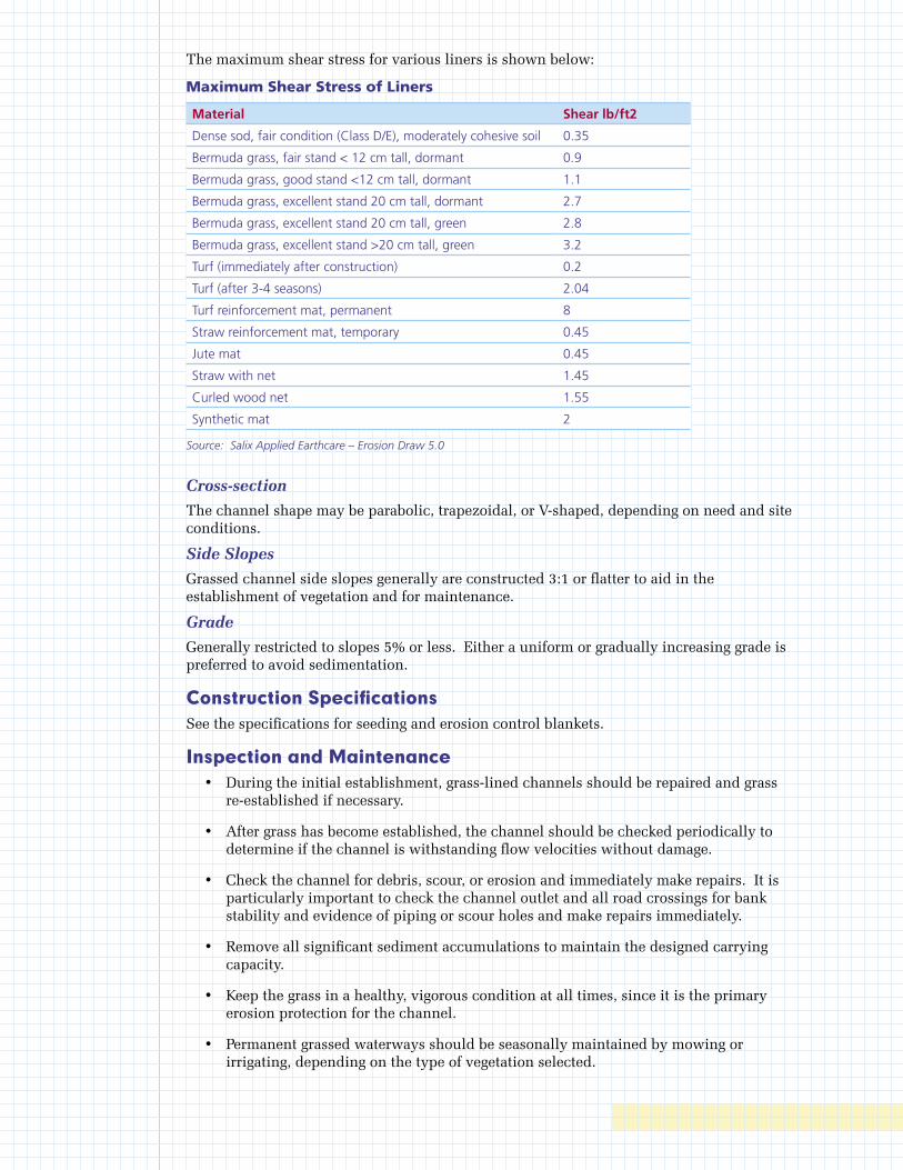
The maximum shear stress for various liners is shown below:
Maximum Shear Stress of Liners
Material Shear lb/ft2
Dense sod, fair condition (Class D/E), moderately cohesive soil 0.35
Bermuda grass, fair stand < 12 cm tall, dormant 0.9
Bermuda grass, good stand <12 cm tall, dormant 1.1
Bermuda grass, excellent stand 20 cm tall, dormant 2.7
Bermuda grass, excellent stand 20 cm tall, green 2.8
Bermuda grass, excellent stand >20 cm tall, green 3.2
Turf (immediately after construction) 0.2
Turf (after 3-4 seasons) 2.04
Turf reinforcement mat, permanent 8
Straw reinforcement mat, temporary 0.45
Jute mat 0.45
Straw with net 1.45
Curled wood net 1.55
Synthetic mat 2
Source: Salix Applied Earthcare – Erosion Draw 5.0
Cross-section
The channel shape may be parabolic, trapezoidal, or V-shaped, depending on need and site conditions.
Side Slopes
Grassed channel side slopes generally are constructed 3:1 or flatter to aid in the establishment of vegetation and for maintenance.
Grade
Generally restricted to slopes 5% or less. Either a uniform or gradually increasing grade is preferred to avoid sedimentation.
Construction SpecificationsSee the specifications for seeding and erosion control blankets.
Inspection and Maintenance • During the initial establishment, grass-lined channels should be repaired and grass
re-established if necessary.
• After grass has become established, the channel should be checked periodically to determine if the channel is withstanding flow velocities without damage.
• Check the channel for debris, scour, or erosion and immediately make repairs. It is particularly important to check the channel outlet and all road crossings for bank stability and evidence of piping or scour holes and make repairs immediately.
• Remove all significant sediment accumulations to maintain the designed carrying capacity.
• Keep the grass in a healthy, vigorous condition at all times, since it is the primary erosion protection for the channel.
• Permanent grassed waterways should be seasonally maintained by mowing or irrigating, depending on the type of vegetation selected.

Check Dam
Defi nitionA rock check dam is a small temporary dam constructed across a swale or channel.
PurposeThe purpose of a check dam is to reduce the velocity of concentrated stormwater fl ows, thereby reducing erosion of the swale or channel. This practice also traps sediment.
Design CriteriaCheck dams shall be limited to use in small, open channels that drain 10 acres or less. Check dams shall not be used in streams. Check dams are especially applicable where the slope of channels is close to the maximum for a grass lining.
The maximum height of a check dam shall be three feet above the ground on which the rock is placed.
The center of the check dam above the fl at portion of the channel shall be at least 6 inches lower than the outer edges.
The maximum spacing between rock check dams in a ditch should be such that the toe of the upstream dam is at the same elevation as the top of the downstream dam.
Construction Specifi cationsStone check dams shall be constructed of KYTC Class 2 channel lining.
Stone shall be placed by hand or mechanically as necessary to achieve complete coverage of the ditch and to ensure that the center of the dam is at least 6 inches lower than the outer edges.
Check dams must be removed when their useful life has been completed. In temporary ditches and swales, check dams shall be removed and the ditch fi lled in when it is no longer needed. In permanent channels, check dams shall be removed when a permanent lining can be installed. In the case of grass-lined ditches, check dams shall be removed when the grass has matured suffi ciently to protect the ditch or swale. The area beneath the check dams shall be seeded and mulched or sodded (depending upon velocity) immediately after check dams are removed.
If stone check dams are used in grass-lined channels that will be mowed, care shall be taken to remove all stone from the channel when the dam is removed. This shall include any stone that has washed downstream.

Inspection and MaintenanceRegular inspections shall be made to ensure that the measure is in good working order and the center of the dam is lower than the edges. Erosion caused by high flows around the edges of the dam shall be corrected immediately, and the dam shall be extended beyond the repaired area.
Check dams shall be checked for sediment accumulation weekly and after each rainfall greater than 0.5 inches. Sediment shall be removed when it reaches one-half of the original height.
Check dams shall remain in place and operational until the drainage area and channel are completely stabilized, or up to 30 days after the permanent site stabilization is achieved.
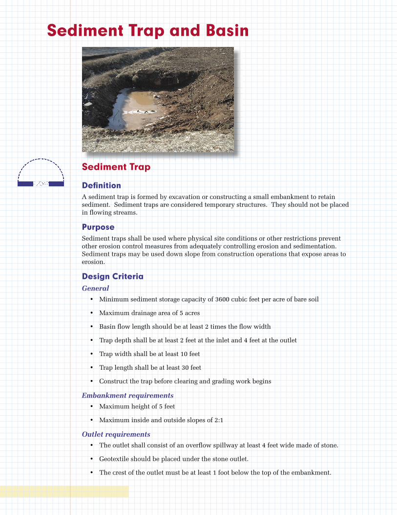
Sediment Trap and Basin
Sediment Trap
Defi nitionA sediment trap is formed by excavation or constructing a small embankment to retain sediment. Sediment traps are considered temporary structures. They should not be placed in fl owing streams.
PurposeSediment traps shall be used where physical site conditions or other restrictions prevent other erosion control measures from adequately controlling erosion and sedimentation. Sediment traps may be used down slope from construction operations that expose areas to erosion.
Design CriteriaGeneral
• Minimum sediment storage capacity of 3600 cubic feet per acre of bare soil
• Maximum drainage area of 5 acres
• Basin fl ow length should be at least 2 times the fl ow width
• Trap depth shall be at least 2 feet at the inlet and 4 feet at the outlet
• Trap width shall be at least 10 feet
• Trap length shall be at least 30 feet
• Construct the trap before clearing and grading work begins
Embankment requirements
• Maximum height of 5 feet
• Maximum inside and outside slopes of 2:1
Outlet requirements
• The outlet shall consist of an overfl ow spillway at least 4 feet wide made of stone.
• Geotextile should be placed under the stone outlet.
• The crest of the outlet must be at least 1 foot below the top of the embankment.
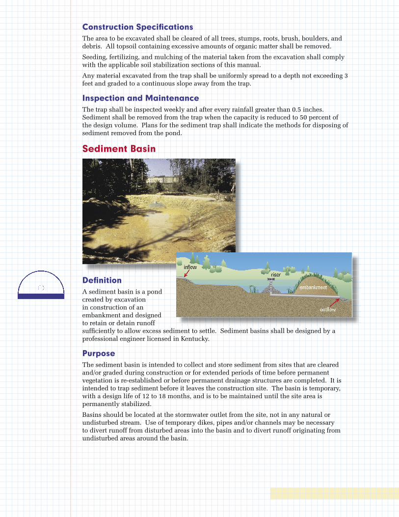
Construction Specifi cationsThe area to be excavated shall be cleared of all trees, stumps, roots, brush, boulders, and debris. All topsoil containing excessive amounts of organic matter shall be removed.
Seeding, fertilizing, and mulching of the material taken from the excavation shall comply with the applicable soil stabilization sections of this manual.
Any material excavated from the trap shall be uniformly spread to a depth not exceeding 3 feet and graded to a continuous slope away from the trap.
Inspection and MaintenanceThe trap shall be inspected weekly and after every rainfall greater than 0.5 inches. Sediment shall be removed from the trap when the capacity is reduced to 50 percent of the design volume. Plans for the sediment trap shall indicate the methods for disposing of sediment removed from the pond.
Sediment Basin
Defi nitionA sediment basin is a pond created by excavation in construction of an embankment and designed to retain or detain runoff suffi ciently to allow excess sediment to settle. Sediment basins shall be designed by a professional engineer licensed in Kentucky.
PurposeThe sediment basin is intended to collect and store sediment from sites that are cleared and/or graded during construction or for extended periods of time before permanent vegetation is re-established or before permanent drainage structures are completed. It is intended to trap sediment before it leaves the construction site. The basin is temporary, with a design life of 12 to 18 months, and is to be maintained until the site area is permanently stabilized.
Basins should be located at the stormwater outlet from the site, not in any natural or undisturbed stream. Use of temporary dikes, pipes and/or channels may be necessary to divert runoff from disturbed areas into the basin and to divert runoff originating from undisturbed areas around the basin.

Design CriteriaThe basin should be designed using SEDCAD or other computer program. The design criteria are listed below:
General
• Minimum sediment storage capacity of 3600 cubic feet per acre of bare soil
• Reduce the total suspended solids by 80% for the 10-year 24-hour storm, or provide a detention time of 24 to 48 hours for the 10-year 24-hour storm
• Minimum drainage area of 5 acres
• Maximum drainage area of 100 acres
• Basin flow length should be at least 2 times the flow width
• Construct the basin before clearing and grading work begins
Embankment requirements
• Maximum inside and outside slopes of 3:1
• Minimum 1 foot freeboard during the 100-year 6-hour storm
• Antiseep collars are required
• Minimum top width of 12 feet
Principal spillway (riser and barrel) requirements
• Use a subsurface drain and/or a solid riser pipe with sufficient dewatering holes to provide sufficient detention time
• Reduce the peak flow to pre-development levels for the 2-year and 10-year 24-hour storms
• Minimum pipe outlet of 8 inches
• Anti-vortex and trash rack required
• Minimum 1 foot freeboard from top of riser to crest of emergency spillway
Emergency spillway requirements
• Designed to pass the 100-year 6-hour post development peak flow
• Crest elevation at least one foot above the tip of the riser pipe
• Minimum 1 foot freeboard during the 100-year 6-hour storm to the top of the embankment
KY Division of Water Dam Safety Requirements
The sediment basin may have to be designed in accordance with dam safety requirements of the KY Division of Water. A dam is defined as any impounding structure that is either 25 feet in height, measured from the downstream toe to the crest, or has a maximum impounding capacity of 50 acre-feet of water. Structures that do not meet these criteria but have the potential to cause significant property damage or pose a threat to loss of life in the downstream area are regulated in the same manner as dams.
Construction Specifications • Construct the basin by excavating or building an embankment before any clearing or
grading work begins.
• Areas under the embankment and any structural works shall be cleared, grubbed and stripped of any vegetation and rootmat as shown on the erosion and sediment control plan.
• In order to facilitate cleanout and restoration, the basin area shall be cleared, grubbed and stripped of any vegetation.
• A cut-off trench shall be excavated along the centerline of the earth fill embankments. The minimum depth shall be 2 feet. The cut-off trench shall extend up both abutments to the riser crest elevation.
• Fill material for the embankment should be clean mineral soil free of roots, woody vegetation, oversized stones, rocks or other objectionable material.
• Fill material shall be placed in 6 inch lifts, continuous layers over the entire length of the fill. Compacting shall be obtained by routing the hauling equipment over the fill so that the entire surface of each layer of the fill is traversed by at least one wheel or tread track of the equipment, or by the use of a compactor. Each layer shall be compacted to 95 percent of maximum density and +/- 2 percent of optimum moisture content.
• The embankment should be constructed to an elevation of 10 percent higher than the design height to allow for settlement if compacting is achieved with hauling equipment. If compactors are used for compacting, the overbuild may be reduced to not less than 5 percent.
• The principle spillway riser shall be securely attached to the discharge pipe by welding all around. All connections shall be watertight.
• The pipe and riser shall be placed on a firm, smooth soil foundation. The connection between the riser and the riser base shall be watertight. Pervious materials such as sand, gravel or crushed stone shall not be used as backfill around the pipe or anti-seep collars.
• The fill material around the pipe spillway shall be placed in 4-inch layers and compacted under the shoulders and around the pipe to at least the same density as the adjacent embankment. A minimum of 2 feet of compacted backfill shall be placed over the pipe spillway before crossing it with construction equipment.
• Steel base plates shall have at least 2 1/2 feet of compacted earth, stone or gravel over them to prevent flotation.
• The emergency spillway shall not be installed in fill.
• Baffles, if used, shall be constructed of 4 inch by 4 inch posts and of 4 foot by 8 foot - ½ inch exterior plywood. The posts shall be set at least 3 feet into the ground, no farther apart than 8 feet center to center, and shall reach a height 6 inches below the riser crest elevation.
• The embankment and emergency spillway shall be stabilized with vegetation immediately following construction.
• Construction operations shall be carried out in such a manner that erosion and water pollution will be minimized.
• Local and state requirements shall be met concerning fencing and signs warning the public of hazards of soft sediment and floodwater.

Inspection and Maintenance • Inspect weekly and after each rainfall greater than 0.5 inches.
• All damages caused by soil erosion or construction equipment shall be repaired before the end of each working day.
• Remove sediment when the sediment storage zone is half full. This sediment shall be placed in such a manner that it will not erode from the site. The sediment shall not be deposited downstream from the embankment or in or adjacent to a stream or floodplain.
• When temporary structures have served their intended purpose and the contributing drainage area has been properly stabilized, the embankment and resulting sediment deposit shall be leveled or otherwise disposed of in accordance with the approved erosion and sediment control plan.
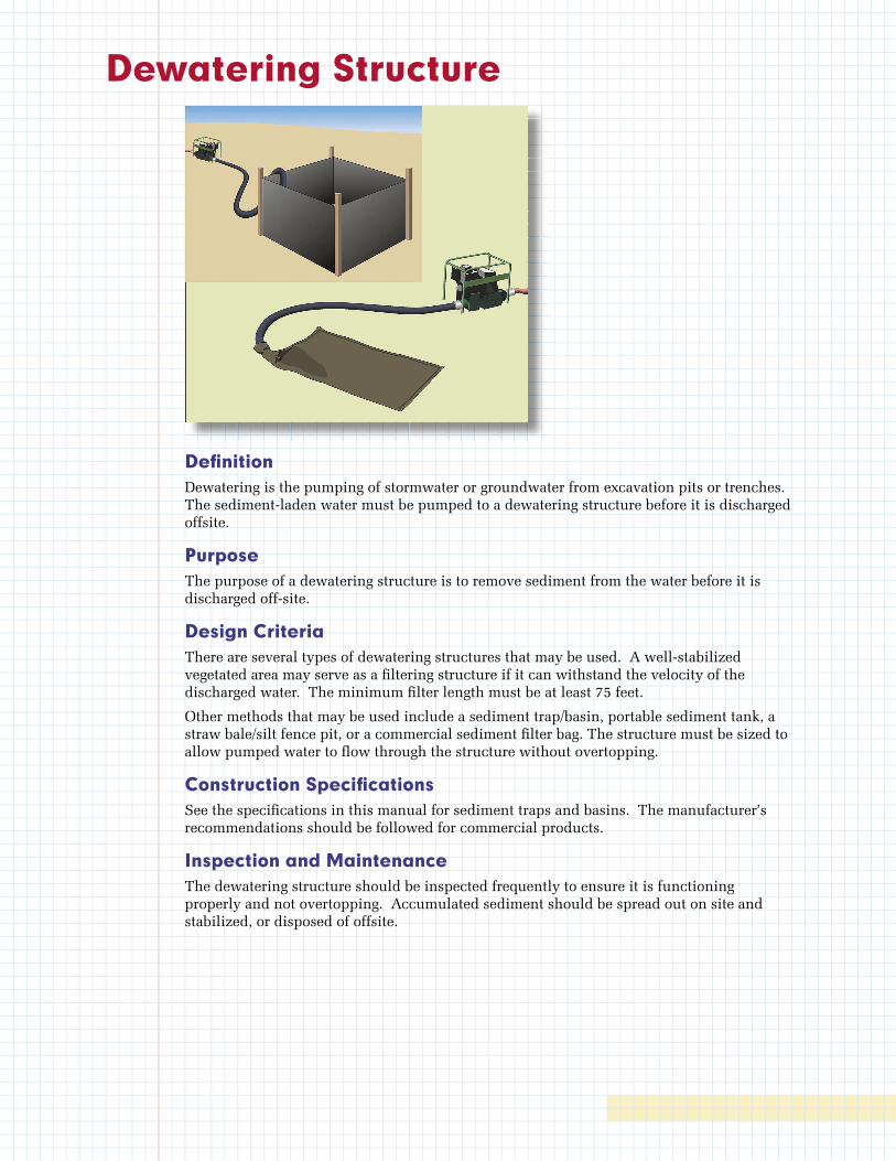
Dewatering Structure
Defi nitionDewatering is the pumping of stormwater or groundwater from excavation pits or trenches. The sediment-laden water must be pumped to a dewatering structure before it is discharged offsite.
PurposeThe purpose of a dewatering structure is to remove sediment from the water before it is discharged off-site.
Design CriteriaThere are several types of dewatering structures that may be used. A well-stabilized vegetated area may serve as a fi ltering structure if it can withstand the velocity of the discharged water. The minimum fi lter length must be at least 75 feet.
Other methods that may be used include a sediment trap/basin, portable sediment tank, a straw bale/silt fence pit, or a commercial sediment fi lter bag. The structure must be sized to allow pumped water to fl ow through the structure without overtopping.
Construction Specifi cationsSee the specifi cations in this manual for sediment traps and basins. The manufacturer’s recommendations should be followed for commercial products.
Inspection and MaintenanceThe dewatering structure should be inspected frequently to ensure it is functioning properly and not overtopping. Accumulated sediment should be spread out on site and stabilized, or disposed of offsite.
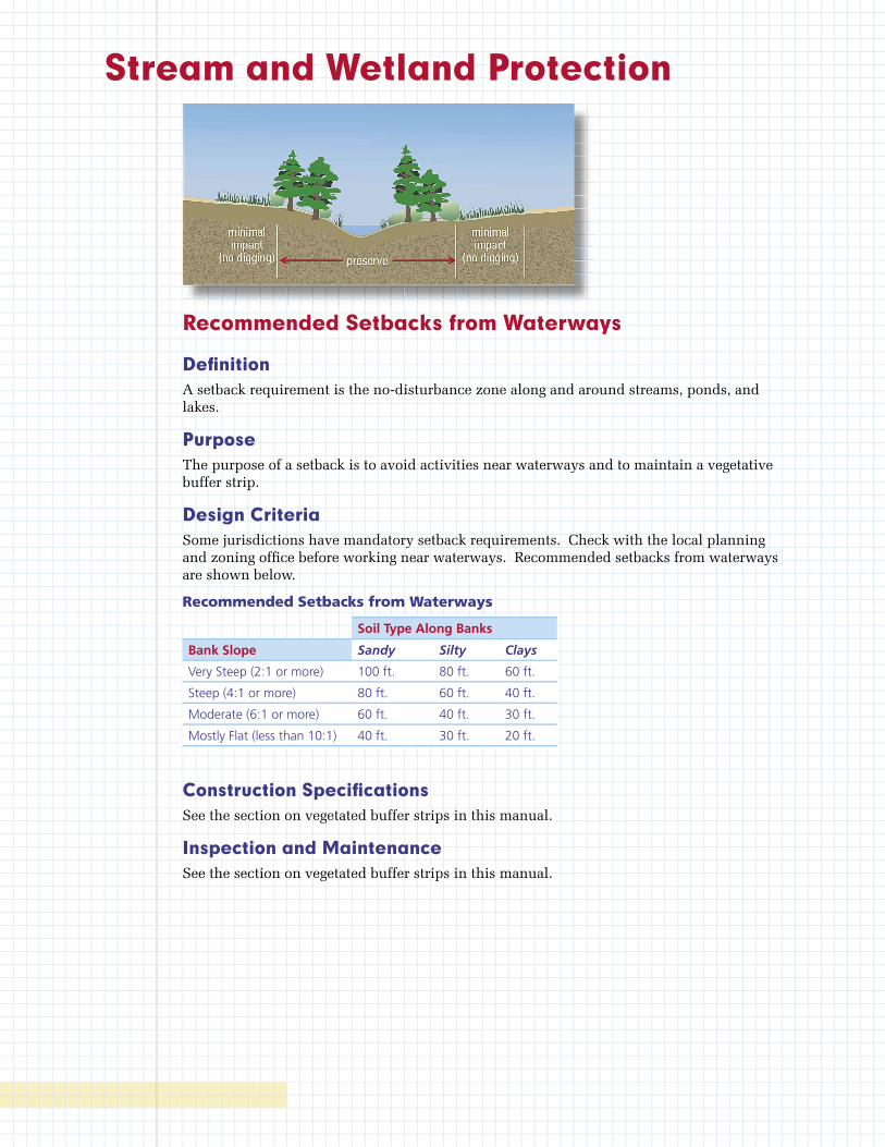
Stream and Wetland Protection
Recommended Setbacks from Waterways
Defi nitionA setback requirement is the no-disturbance zone along and around streams, ponds, and lakes.
Purpose The purpose of a setback is to avoid activities near waterways and to maintain a vegetative buffer strip.
Design CriteriaSome jurisdictions have mandatory setback requirements. Check with the local planning and zoning offi ce before working near waterways. Recommended setbacks from waterways are shown below.
Recommended Setbacks from Waterways
Soil Type Along Banks
Bank Slope Sandy Silty Clays
Very Steep (2:1 or more) 100 ft. 80 ft. 60 ft.
Steep (4:1 or more) 80 ft. 60 ft. 40 ft.
Moderate (6:1 or more) 60 ft. 40 ft. 30 ft.
Mostly Flat (less than 10:1) 40 ft. 30 ft. 20 ft.
Construction Specifi cationsSee the section on vegetated buffer strips in this manual.
Inspection and MaintenanceSee the section on vegetated buffer strips in this manual.
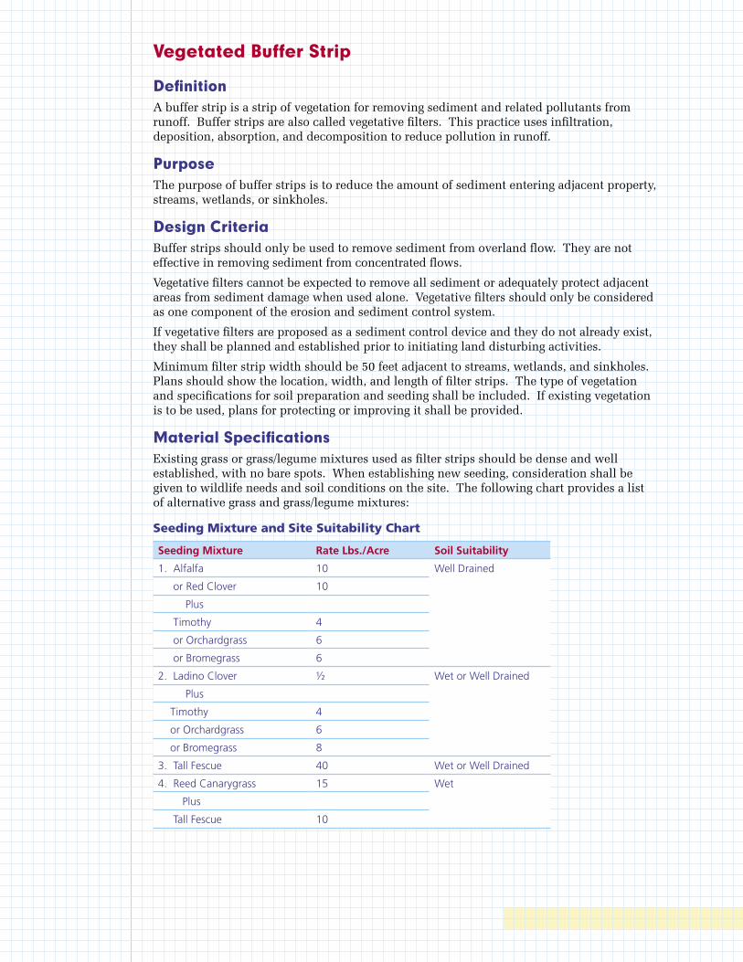
Vegetated Buffer Strip
DefinitionA buffer strip is a strip of vegetation for removing sediment and related pollutants from runoff. Buffer strips are also called vegetative filters. This practice uses infiltration, deposition, absorption, and decomposition to reduce pollution in runoff.
PurposeThe purpose of buffer strips is to reduce the amount of sediment entering adjacent property, streams, wetlands, or sinkholes.
Design CriteriaBuffer strips should only be used to remove sediment from overland flow. They are not effective in removing sediment from concentrated flows.
Vegetative filters cannot be expected to remove all sediment or adequately protect adjacent areas from sediment damage when used alone. Vegetative filters should only be considered as one component of the erosion and sediment control system.
If vegetative filters are proposed as a sediment control device and they do not already exist, they shall be planned and established prior to initiating land disturbing activities.
Minimum filter strip width should be 50 feet adjacent to streams, wetlands, and sinkholes. Plans should show the location, width, and length of filter strips. The type of vegetation and specifications for soil preparation and seeding shall be included. If existing vegetation is to be used, plans for protecting or improving it shall be provided.
Material SpecificationsExisting grass or grass/legume mixtures used as filter strips should be dense and well established, with no bare spots. When establishing new seeding, consideration shall be given to wildlife needs and soil conditions on the site. The following chart provides a list of alternative grass and grass/legume mixtures:
Seeding Mixture and Site Suitability Chart
Seeding Mixture Rate Lbs./Acre Soil Suitability
1. Alfalfa 10 Well Drained
or Red Clover 10
Plus
Timothy 4
or Orchardgrass 6
or Bromegrass 6
2. Ladino Clover ½ Wet or Well Drained
Plus
Timothy 4
or Orchardgrass 6
or Bromegrass 8
3. Tall Fescue 40 Wet or Well Drained
4. Reed Canarygrass 15 Wet
Plus
Tall Fescue 10
Construction SpecificationsWhen planting filter strips, prepare seedbed, incorporate fertilizer, and apply mulch consistent with the seeding sections of this manual. Filter strips using areas of existing vegetation shall be over seeded, as necessary, with the above mixtures to obtain an equivalent density of vegetation. The over seeding shall be accomplished prior to the land disturbing activity.
Inspection and MaintenanceFilter strips shall be inspected regularly to ensure that a healthy vegetative growth is maintained. Any bare spots or spots where sediment deposition could lead to the destruction of vegetation shall be repaired.
Filter strips shall be fertilized once each year in the fall. Construction traffic shall not be permitted to drive upon filter strips.
Stream Crossing
DefinitionA temporary stream crossing is a temporary structural span installed across a flowing stream use by construction traffic. Structures may include bridges, round pipes, or pipe arches.
PurposeThe purpose of a temporary stream crossing is to provide a means for construction traffic to cross flowing streams without damaging the channel or banks and to keep sediment generated by construction traffic out of the stream.
Design Criteria • Temporary stream crossings are applicable to flowing streams with drainage areas less
than one square mile. Structures that must handle flow from larger drainage areas shall be designed as permanent structures by a licensed professional engineer.
• Temporary stream crossings shall be planned to be in service for the shortest practical period of time and to be removed as soon as their function is completed.
• Such structures are subject to the rules and regulations of the U.S. Army Corps of Engineers for in-stream modifications (404 permits) and the KY Division of Water (401 certification).
• The span shall be designed to withstand the expected loads from heavy construction equipment that will cross the structure.
• The structure shall be large enough to convey the peak flow expected from a 2-year storm without appreciably altering the stream flow characteristics. The structure may be a span, a culvert, or multiple culverts. The minimum sized culvert shall be 24 inches.
• Where culverts are installed, compacted soil or rock shall be used to form the crossing. The depth of soil or rock cover over the culvert shall be equal to one-half the diameter of the culvert or 12 inches, whichever is greater. The sides of the fill shall be protected from erosion using the mulching and seeding erosion control measures specified in this manual.
• The slope of the culvert shall be at least 0.25 inch per foot.

Material Specifications • When using a culvert crossing, the top of a compacted earth fill shall be covered with
six inches of KYTC No. 2 stone.
• No. 2 stone shall also be used for the stone pads forming the crossing approaches.
Construction Specifications • Clearing and excavation of the streambed and banks shall be kept to a minimum.
• The structure shall be removed as soon as it is no longer necessary for project construction.
• Upon removal of the structure, the stream shall immediately be reshaped to its original cross section and properly stabilized.
• The approaches to the structure shall consist of stone pads with a minimum thickness of 6 inches, a minimum width equal to the width of the structure and a minimum approach length of 25 feet on each side.
Maintenance • The structure shall be inspected after every rainfall greater than 0.5 inches and at
least once a week and all damages repaired immediately.

Bioengineering Streambank Stabilization
Live Staking
Defi nitionLive stake planting involves the insertion and tamping of live, vegetative cuttings into the ground in a manner that allows the stake to take root and grow.
PurposeUsing a system of live stakes creates a root mat that stabilizes the soil by reinforcing and binding soil particles together and by extracting excess soil moisture. The practice is commonly used in conjunction with other practices to provide for a more stable site condition (i.e., used to anchor blankets, coir mats, turf reinforcement mats, straw rolls, etc.).
Live stakes can be used for the following:
• Repair of small earth slips and slumps.
• Gullies and stream channels can be live-staked. Areas best suited to staking are the bottoms and banks of small gullies and bare gully banks.
• Live stakes can be inserted or driven through interstices or openings in gabions, riprap, articulated block, or cellular confi nement systems.
• Live willow stakes can be used to anchor and enhance the effectiveness of willow wattles, straw rolls, coir rolls, turf reinforcement mats, coir mats, and other erosion control materials.
• Willow staking enhances conditions for natural invasion and the establishment of other plants from the surrounding plant community.
• Willow establishment can improve aesthetics and provide wildlife habitat.
• As a temporary measure, live willow staking performs an important function of stabilizing and modifying the soil, serving as a pioneer species until other plants become established.
• Several species of willow will grow from cuttings in less favorable soil conditions such as road fi lls and gullies in bare denuded land. Even in very unfavorable sites willow cuttings will often grow vigorously for a few years before they die out.
Live Staking Live Staking Live Staking Live Staking Live Staking Live Staking Live Staking Live Staking Live Staking Live Staking
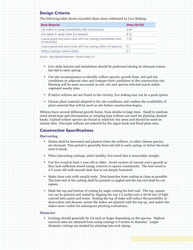
Design CriteriaThe following table shows recorded shear stress withstood by Live Staking.
Bank Material Shear (lb/ft2)
Live stakes in riprap (immediately after construction) 2.04
Live stakes in riprap (after 3-4 seasons) 6.12
Coarse gravel and stone cover with live cuttings (immediately after construction)
1.02
Coarse gravel and stone cover with live cuttings (after 3-4 seasons) 5.1
Willow cuttings / willow stakes 2.1
Source: Salix Applied Earthcare - Erosion Draw 5.0
• Live stake harvest and installation should be performed during its dormant season, late fall to early spring.
• Use site reconnaissance to identify willow species, growth form, soil and site conditions on adjacent sites and compare their conditions to the construction site. Planting will be more successful as soil, site and species selected match stable, vegetated nearby sites.
• If native willows are not found in the vicinity, live staking may not be a good option.
• Choose plant material adapted to the site conditions and confirm the availability of plant material that will be used on site before construction begins.
Willows have several different growth forms, from shrubs to large trees. Small to medium sized shrub-type and rhizomatous or creeping-type willows are used for planting channel banks. Upland willow species are found in relatively dry areas and should be used on similar sites. Tree-type willows are selected for the upper bank and flood plain area.
Construction Specifications Harvesting
• Stakes shall be harvested and planted when the willows, or other chosen species, are dormant. This period is generally from late fall to early spring, or before the buds start to break.
• When harvesting cuttings, select healthy, live wood that is reasonably straight.
• Use live wood at least 1 year old or older. Avoid suckers of current year’s growth as they lack sufficient stored energy reserves to sprout consistently. The best wood is 2-5 years old with smooth bark that is not deeply furrowed.
• Make clean cuts with unsplit ends. Trim branches from cutting as close as possible. The butt end of the cutting shall be pointed or angled and the top end shall be cut square.
• Mark the top and bottom of cutting by angle cutting the butt end. The top, square cut can be painted and sealed by dipping the top 1-2 inches into a 50-50 mix of light colored latex paint and water. Sealing the top of stake will reduce the possibility of desiccation and disease, assure the stakes are planted with the top up, and makes the stakes more visible for subsequent planting evaluations.
Diameter
• Cuttings should generally be 3/4 inch or larger depending on the species. Highest survival rates are obtained from using cuttings 2-3 inches in diameter. Larger diameter cuttings are needed for planting into rock riprap.
Length
• Cuttings of small diameter (up to 1 1/2 inches) shall be 18 inches long minimum. Thicker cuttings should be longer.
• No less than 1/2 total length must be into the ground.
• Stakes should be cut so that a terminal bud scar is within 1-4 inches of the top. At least two buds and/or bud scars shall be above the ground after planting.
Installation
• Stakes must not be allowed to dry out. The cuttings should be installed the same day they are harvested. If this is not possible, they should be soaked in water for a minimum of 24 hours.
• Plant stakes 1-3 feet apart.
• Set the stake as deep as possible into the soil, preferably with 80 percent of its length into the soil and in contact with mid-summer water table.
• It is essential to have good contact between the stake and soil for roots to sprout. Tamp the soil around the cutting.
• Use an iron stake or bar to make a pilot hole in firm soil.
• Do not damage the buds, strip the bark or split the stake during installation.
• Split or damaged stakes shall be removed and replaced.
• Stakes must be planted with butt-ends into the ground. Leaf bud scars or emerging buds should always point up.
Inspection and Maintenance • All temporary and permanent erosion and sediment control practices shall be
maintained and repaired as needed to assure continued performance of their intended function.
• Streambanks and steep slopes are highly susceptible to erosion and damage from significant storm events. Willow stakes alone provide very little initial site protection during the establishment period.
• Periodic inspection repair and maintenance will be required during the first two years or until the vegetation is established.
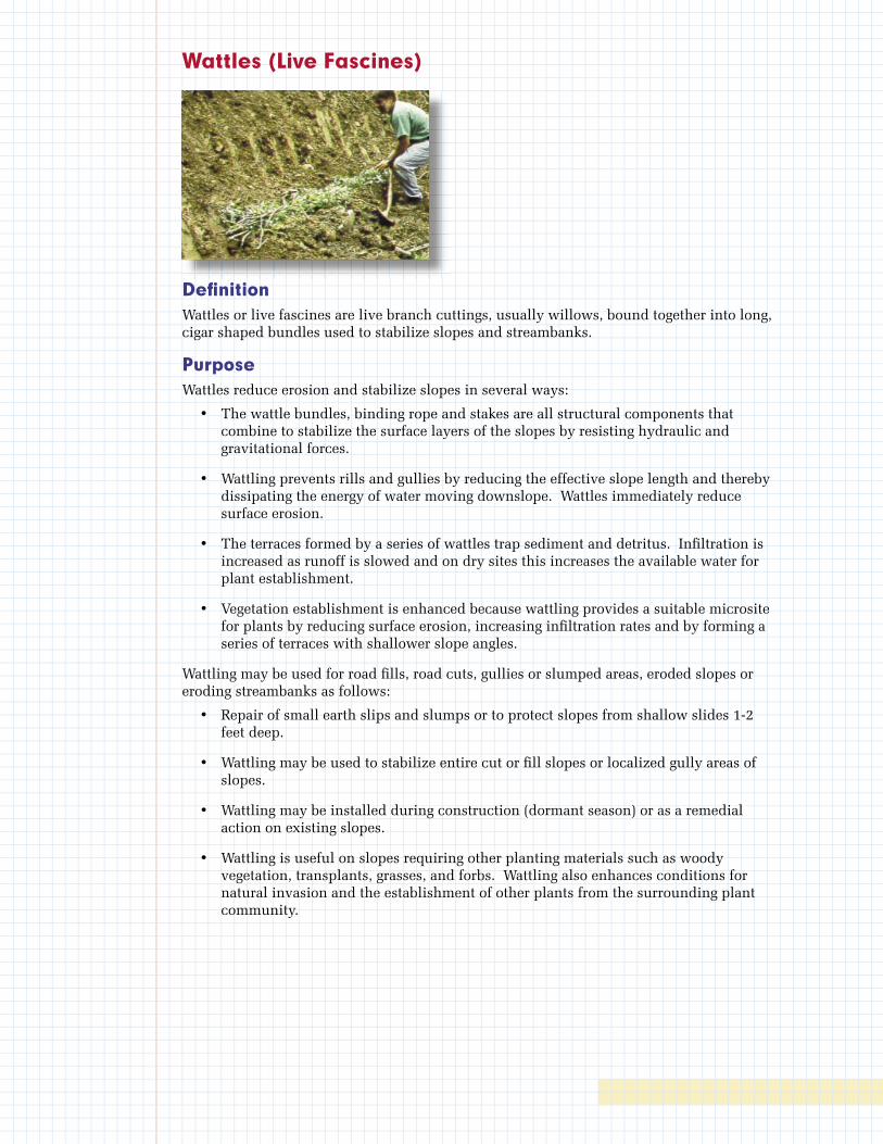
Wattles (Live Fascines)
Defi nitionWattles or live fascines are live branch cuttings, usually willows, bound together into long, cigar shaped bundles used to stabilize slopes and streambanks.
PurposeWattles reduce erosion and stabilize slopes in several ways:
• The wattle bundles, binding rope and stakes are all structural components that combine to stabilize the surface layers of the slopes by resisting hydraulic and gravitational forces.
• Wattling prevents rills and gullies by reducing the effective slope length and thereby dissipating the energy of water moving downslope. Wattles immediately reduce surface erosion.
• The terraces formed by a series of wattles trap sediment and detritus. Infi ltration is increased as runoff is slowed and on dry sites this increases the available water for plant establishment.
• Vegetation establishment is enhanced because wattling provides a suitable microsite for plants by reducing surface erosion, increasing infi ltration rates and by forming a series of terraces with shallower slope angles.
Wattling may be used for road fi lls, road cuts, gullies or slumped areas, eroded slopes or eroding streambanks as follows:
• Repair of small earth slips and slumps or to protect slopes from shallow slides 1-2 feet deep.
• Wattling may be used to stabilize entire cut or fi ll slopes or localized gully areas of slopes.
• Wattling may be installed during construction (dormant season) or as a remedial action on existing slopes.
• Wattling is useful on slopes requiring other planting materials such as woody vegetation, transplants, grasses, and forbs. Wattling also enhances conditions for natural invasion and the establishment of other plants from the surrounding plant community.
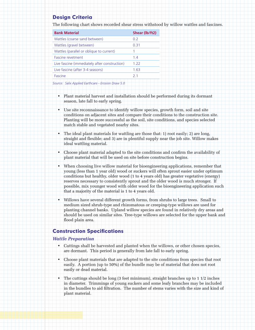
Design CriteriaThe following chart shows recorded shear stress withstood by willow wattles and fascines.
Bank Material Shear (lb/ft2)
Wattles (coarse sand between) 0.2
Wattles (gravel between) 0.31
Wattles (parallel or oblique to current) 1
Fascine revetment 1.4
Live fascine (immediately after construction) 1.22
Live fascine (after 3-4 seasons) 1.63
Fascine 2.1
Source: Salix Applied Earthcare - Erosion Draw 5.0
• Plant material harvest and installation should be performed during its dormant season, late fall to early spring.
• Use site reconnaissance to identify willow species, growth form, soil and site conditions on adjacent sites and compare their conditions to the construction site. Planting will be more successful as the soil, site conditions, and species selected match stable and vegetated nearby sites.
• The ideal plant materials for wattling are those that: 1) root easily; 2) are long, straight and flexible; and 3) are in plentiful supply near the job site. Willow makes ideal wattling material.
• Choose plant material adapted to the site conditions and confirm the availability of plant material that will be used on site before construction begins.
• When choosing live willow material for bioengineering applications, remember that young (less than 1 year old) wood or suckers will often sprout easier under optimum conditions but healthy, older wood (1 to 4 years old) has greater vegetative (energy) reserves necessary to consistently sprout and the older wood is much stronger. If possible, mix younger wood with older wood for the bioengineering application such that a majority of the material is 1 to 4 years old.
• Willows have several different growth forms, from shrubs to large trees. Small to medium sized shrub-type and rhizomatous or creeping-type willows are used for planting channel banks. Upland willow species are found in relatively dry areas and should be used on similar sites. Tree-type willows are selected for the upper bank and flood plain area.
Construction SpecificationsWattle Preparation
• Cuttings shall be harvested and planted when the willows, or other chosen species, are dormant. This period is generally from late fall to early spring.
• Choose plant materials that are adapted to the site conditions from species that root easily. A portion (up to 50%) of the bundle may be of material that does not root easily or dead material.
• The cuttings should be long (3 feet minimum), straight branches up to 1 1/2 inches in diameter. Trimmings of young suckers and some leafy branches may be included in the bundles to aid filtration. The number of stems varies with the size and kind of plant material.
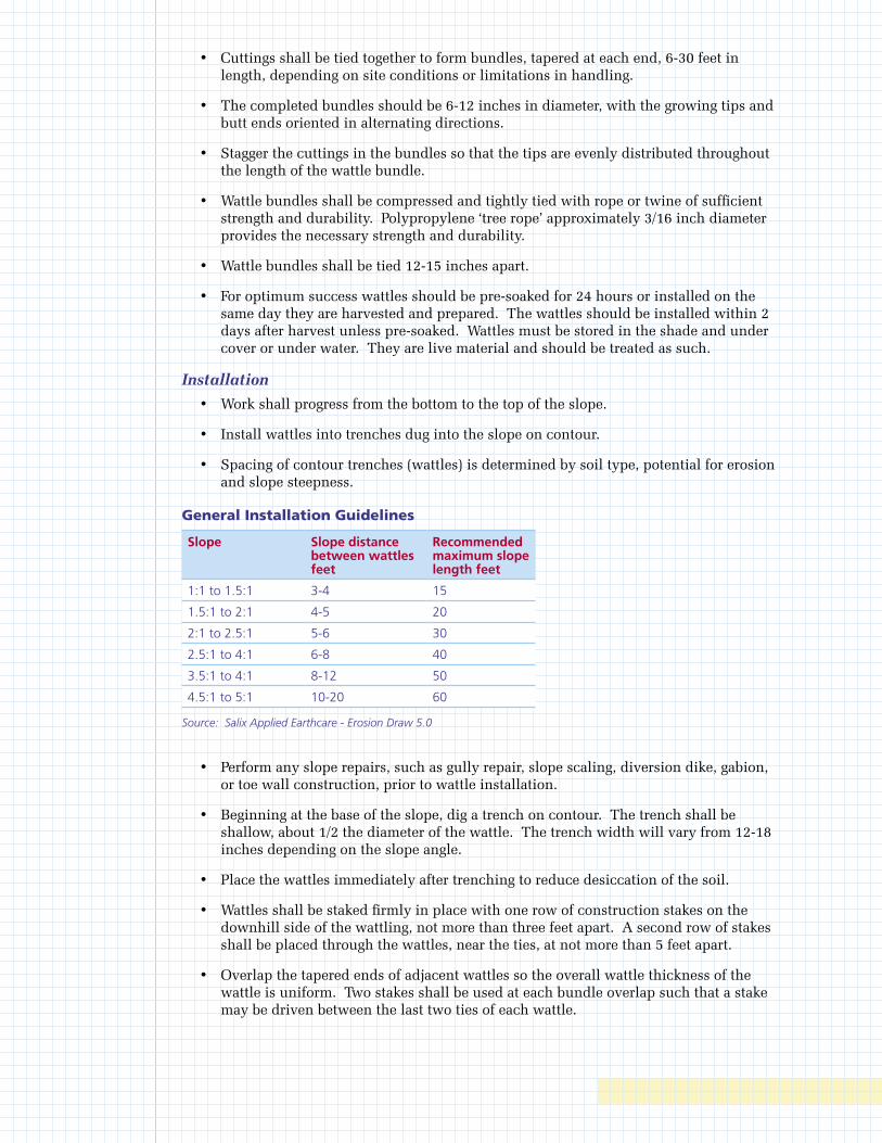
• Cuttings shall be tied together to form bundles, tapered at each end, 6-30 feet in length, depending on site conditions or limitations in handling.
• The completed bundles should be 6-12 inches in diameter, with the growing tips and butt ends oriented in alternating directions.
• Stagger the cuttings in the bundles so that the tips are evenly distributed throughout the length of the wattle bundle.
• Wattle bundles shall be compressed and tightly tied with rope or twine of sufficient strength and durability. Polypropylene ‘tree rope’ approximately 3/16 inch diameter provides the necessary strength and durability.
• Wattle bundles shall be tied 12-15 inches apart.
• For optimum success wattles should be pre-soaked for 24 hours or installed on the same day they are harvested and prepared. The wattles should be installed within 2 days after harvest unless pre-soaked. Wattles must be stored in the shade and under cover or under water. They are live material and should be treated as such.
Installation
• Work shall progress from the bottom to the top of the slope.
• Install wattles into trenches dug into the slope on contour.
• Spacing of contour trenches (wattles) is determined by soil type, potential for erosion and slope steepness.
General Installation Guidelines
Slope Slope distance between wattles feet
Recommended maximum slope length feet
1:1 to 1.5:1 3-4 15
1.5:1 to 2:1 4-5 20
2:1 to 2.5:1 5-6 30
2.5:1 to 4:1 6-8 40
3.5:1 to 4:1 8-12 50
4.5:1 to 5:1 10-20 60
Source: Salix Applied Earthcare - Erosion Draw 5.0
• Perform any slope repairs, such as gully repair, slope scaling, diversion dike, gabion, or toe wall construction, prior to wattle installation.
• Beginning at the base of the slope, dig a trench on contour. The trench shall be shallow, about 1/2 the diameter of the wattle. The trench width will vary from 12-18 inches depending on the slope angle.
• Place the wattles immediately after trenching to reduce desiccation of the soil.
• Wattles shall be staked firmly in place with one row of construction stakes on the downhill side of the wattling, not more than three feet apart. A second row of stakes shall be placed through the wattles, near the ties, at not more than 5 feet apart.
• Overlap the tapered ends of adjacent wattles so the overall wattle thickness of the wattle is uniform. Two stakes shall be used at each bundle overlap such that a stake may be driven between the last two ties of each wattle.
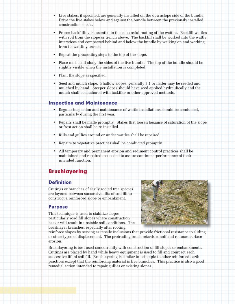
• Live stakes, if specifi ed, are generally installed on the downslope side of the bundle. Drive the live stakes below and against the bundle between the previously installed construction stakes.
• Proper backfi lling is essential to the successful rooting of the wattles. Backfi ll wattles with soil from the slope or trench above. The backfi ll shall be worked into the wattle interstices and compacted behind and below the bundle by walking on and working from its wattling terrace.
• Repeat the proceeding steps to the top of the slope.
• Place moist soil along the sides of the live bundle. The top of the bundle should be slightly visible when the installation is completed.
• Plant the slope as specifi ed.
• Seed and mulch slope. Shallow slopes, generally 3:1 or fl atter may be seeded and mulched by hand. Steeper slopes should have seed applied hydraulically and the mulch shall be anchored with tackifi er or other approved methods.
Inspection and Maintenance • Regular inspection and maintenance of wattle installations should be conducted,
particularly during the fi rst year.
• Repairs shall be made promptly. Stakes that loosen because of saturation of the slope or frost action shall be re-installed.
• Rills and gullies around or under wattles shall be repaired.
• Repairs to vegetative practices shall be conducted promptly.
• All temporary and permanent erosion and sediment control practices shall be maintained and repaired as needed to assure continued performance of their intended function.
Brushlayering
Defi nitionCuttings or branches of easily rooted tree species are layered between successive lifts of soil fi ll to construct a reinforced slope or embankment.
PurposeThis technique is used to stabilize slopes, particularly road fi ll slopes where construction has or will result in unstable soil conditions. The brushlayer branches, especially after rooting, reinforce slopes by serving as tensile inclusions that provide frictional resistance to sliding or other types of displacement. The protruding brush retards runoff and reduces surface erosion.
Brushlayering is best used concurrently with construction of fi ll slopes or embankments. Cuttings are placed by hand while heavy equipment is used to fi ll and compact each successive lift of soil fi ll. Brushlayering is similar in principle to other reinforced earth practices except that the reinforcing material is live branches. This practice is also a good remedial action intended to repair gullies or existing slopes.
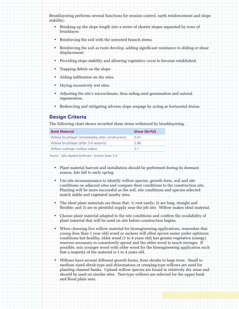
Brushlayering performs several functions for erosion control, earth reinforcement and slope stability:
• Breaking up the slope length into a series of shorter slopes separated by rows of brushlayer.
• Reinforcing the soil with the unrooted branch stems.
• Reinforcing the soil as roots develop, adding significant resistance to sliding or shear displacement.
• Providing slope stability and allowing vegetative cover to become established.
• Trapping debris on the slope.
• Aiding infiltration on dry sites.
• Drying excessively wet sites.
• Adjusting the site’s microclimate, thus aiding seed germination and natural regeneration.
• Redirecting and mitigating adverse slope seepage by acting as horizontal drains.
Design CriteriaThe following chart shows recorded shear stress withstood by brushlayering.
Bank Material Shear (lb/ft2)
Willow brushlayer (immediately after construction) 0.41
Willow brushlayer (after 3-4 seasons) 2.86
Willow cuttings / willow stakes 2.1
Source: Salix Applied Earthcare - Erosion Draw 5.0
• Plant material harvest and installation should be performed during its dormant season, late fall to early spring.
• Use site reconnaissance to identify willow species, growth form, soil and site conditions on adjacent sites and compare their conditions to the construction site. Planting will be more successful as the soil, site conditions and species selected match stable and vegetated nearby sites.
• The ideal plant materials are those that: 1) root easily; 2) are long, straight and flexible; and 3) are in plentiful supply near the job site. Willow makes ideal material.
• Choose plant material adapted to the site conditions and confirm the availability of plant material that will be used on site before construction begins.
• When choosing live willow material for bioengineering applications, remember that young (less than 1 year old) wood or suckers will often sprout easier under optimum conditions but healthy, older wood (1 to 4 years old) has greater vegetative (energy) reserves necessary to consistently sprout and the older wood is much stronger. If possible, mix younger wood with older wood for the bioengineering application such that a majority of the material is 1 to 4 years old.
• Willows have several different growth forms, from shrubs to large trees. Small to medium sized shrub-type and rhizomatous or creeping-type willows are used for planting channel banks. Upland willow species are found in relatively dry areas and should be used on similar sites. Tree-type willows are selected for the upper bank and flood plain area.
• If branch cuttings are not pre-soaked for at least 24 hours, then they shall be harvested no earlier than 48 hours prior to installation. Cuttings must be kept moist and cool at all times between cutting and installation. All cuttings need to be thoroughly wet and covered with moistened wrapping before being transported.
• Construction personnel shall be made aware that brushlayering uses live plant material and must be treated as such.
• Spacing between the brushlayers is determined by the erosion potential of the slope (i.e., soil type, rainfall, and length and steepness of the slope). Spacing may be from 3-8 feet. On long slopes, brushlayer spacing should be closer at the bottom and spacing may increase near the top of the slope.
• Steep slopes (1:1) should not exceed approximately 30 feet in slope length. Reinforced earth design guidelines suggest that the slope height should not exceed 3 times the width of the reinforced volume. Therefore, for brushlayering with 6-8 foot long cuttings, the slope height should not exceed 18-24 feet.
Construction Specifications • Cuttings shall be harvested and planted when the willows, or other chosen species,
are dormant. This period is generally from late fall to early spring.
• Choose plant materials that are adapted to the site conditions from species that root easily.
• Branch cuttings shall be 4-8 feet long, 3/4-2 inches diameter.
• Pre-soak cuttings for a minimum of 24 hours before installing.
• The surface of the bench shall be sloped so the outside edge is higher than the inside so the butt ends angle down slightly into the slope.
• Place branch cuttings, 3-8 inches thick, in a crisscross or over lapping configuration. The growing tips shall protrude 6-12 inches from the slope face with the butt end dipping into the slope.
• Immediately cover brushlayer with 6 inches of fill soil and compact according to construction specifications. Water the soil cover immediately to wet the cuttings and achieve adequate compaction.
• Earth moving equipment shall not travel directly over the cuttings. Six inches of soil must be maintained between the brushlayer and equipment at all times.
• Fill and compact the soil placed above the brushlayer in successive lifts, maximum 6-8 inches deep.
• Install the next brushlayer 3-8 feet above the previous row.
• Seed and mulch slope. Shallow slopes, generally 3:1 or flatter may be seeded and mulched by hand. Steeper slopes should have seed applied hydraulically and the mulch shall be anchored with tackifier or other approved methods.
Inspection and MaintenanceRegular inspection and maintenance of bioengineering installations should be conducted, particularly during the first year. Prompt correction of any failures is essential to prevent major problems from developing.

Waste Management
Debris and Trash Management
Description Large volumes of debris and trash are often generated at construction sites including: packaging, pallets, wood waste, concrete waste, soil, electrical wiring, cuttings, and a variety of other materials. There are several techniques and procedures to minimize the potential of stormwater contamination from solid waste through appropriate storage and disposal practices. Recycling of construction debris also reduces the volume of material to be disposed of and associated costs.
Primary Use Debris and trash management should be a part of all construction practices. By limiting the trash and debris on site, stormwater quality is improved along with reduced clean up requirements at the completion of the project.
Applications Solid waste management for construction sites is based on proper storage and disposal practices by construction workers and supervisors. Key elements of the program are education and modification of improper disposal habits. Cooperation and vigilance is required on the part of supervisors and workers to ensure that the recommendations and procedures are followed. Following are lists describing the targeted materials and recommended procedures:
• Construction (and Demolition) Debris
- Dimensional lumber
- Miscellaneous wood (pallets, plywood, etc.)
- Copper (pipe and electrical wiring)
- Miscellaneous metal (studs, pipe, conduit, sheathing, nails, etc.)
- Insulation
- Concrete, brick, and mortar
- Shingles
- Roofing materials
- Gypsum board
• Trash
- Paper and cardboard (packaging, containers, wrappers)
- Plastic (packaging, bottles, containers)
- Styrofoam (cups, packing, and forms)
- Food and beverage containers
- Food waste
Storage Procedures • Wherever possible, minimize production of debris and trash.
• Designate a foreman or supervisor to oversee and enforce proper debris and trash procedures.
• Instruct construction workers in proper debris and trash storage and handling procedures.
• Segregate potentially hazardous waste from non-hazardous construction site debris.
• Segregate recyclable construction debris from other non-recyclable materials.
• Keep debris and trash under cover either in a closed dumpster or other enclosed trash container that limits contact with rain and runoff and prevents light materials from blowing out.
• Store waste materials away from drainage ditches, swales, and catch basins.
• Do not allow trash containers to overflow.
• Do not allow waste materials to accumulate on the ground.
• Prohibit littering by workers and visitors.
• Police site daily for litter and debris.
• Enforce solid waste handling and storage procedures.
Disposal Procedures • If feasible, recycle construction and demolition debris such as wood, metal, and
concrete.
• General construction debris may be hauled to a licensed construction debris landfill (typically less expensive than a sanitary landfill).
• Use waste and recycling haulers/facilities approved by the local jurisdiction.
Education • Educate all workers on solid waste storage and disposal procedures.
• Instruct workers in identification of solid waste and hazardous waste.
• Have regular meetings to discuss and reinforce disposal procedures (incorporate in regular safety seminars).
• Clearly mark on all debris and trash containers which materials are acceptable.
Quality Control • Foreman and/or construction supervisor shall monitor on-site solid waste storage and
disposal procedures.
• Discipline workers who repeatedly violate procedures.
Requirements • Job-site waste handling and disposal education and awareness program.
• Compliance by workers.
• Sufficient and appropriate waste storage containers.
• Timely removal of stored solid waste materials.
• Training workers and monitoring compliance.
Chemical Management
Description Chemical management addresses the problem of stormwater polluted with chemical pollutants through spills or other forms of contact. The objective of the chemical management is to minimize the potential of stormwater contamination from construction chemicals through appropriate recognition, handling, storage, and disposal practices.
It is not the intent of chemical management to supersede or replace normal site assessment and remediation procedures. Significant spills and/or contamination warrant immediate response by trained professionals. Suspected job-site contamination should be immediately reported to regulatory authorities and protective actions taken.
Primary Use These management practices, along with applicable OSHA and EPA guidelines, should be incorporated at all construction sites that use or generate hazardous wastes. Many chemicals such as fuel, oil, grease, fertilizer, and pesticide are present at most construction sites.
Installation, Application and Disposal Criteria The chemical management techniques presented here are based on proper recognition, handling, and disposal practices by construction workers and supervisors. Key elements are education and proper disposal practices, as well as provisions for safe storage and disposal. Following are lists describing the targeted materials and recommended procedures:
• Targeted Chemical Materials
- Paints
- Solvents
- Stains
- Wood preservatives
- Cutting oils
- Greases
- Roofing tar
- Pesticides, herbicides, and fertilizer
- Fuels and lube oils
- Antifreeze
Storage Procedures • Wherever possible, minimize use of hazardous materials.
• Minimize generation of hazardous wastes on the job-site.
• Segregate potentially hazardous waste from non-hazardous construction site debris.
• Designate a foreman or supervisor to oversee hazardous materials handling procedures.
• Keep chemicals in appropriate containers (closed drums or similar) and under cover.
• Store chemicals away from drainage ditches, swales, and catch basins.
• Use containment berms in fueling and maintenance areas and where the potential for spills is high.
Waste Handling • Ensure that adequate hazardous waste storage volume is available.
• Ensure that hazardous waste collection containers are conveniently located.
• Do not allow potentially hazardous waste materials to accumulate.
• Enforce hazardous waste handling and disposal procedures.
• Clearly mark on all hazardous waste containers which materials are acceptable for the container.
Disposal Procedures • Ensure that adequate cleanup and containment materials are available onsite.
• Regularly schedule hazardous waste removal to minimize on-site storage.
• Use only licensed hazardous waste haulers.
Education • Instruct workers on safety procedures for construction site chemical storage.
• Instruct workers in identification of chemical pollutants.
• Ensure that workers are trained in procedures for spill prevention and response.
• Educate workers of potential dangers to humans and the environment from chemical pollutants.
• Educate all workers on chemical storage and disposal procedures.
• Have regular meetings to discuss and reinforce identification, handling, and disposal procedures (incorporate in regular safety seminars).
• Establish a continuing education program to indoctrinate new employees.
Quality Assurance • Foreman and/or construction supervisor shall monitor on-site chemical storage and
disposal procedures.
• Educate and if necessary, discipline workers who violate procedures.
• Ensure that the hazardous waste disposal contractor is reputable and licensed.
Requirements • Job-site chemical and hazardous waste handling and disposal education and
awareness program.
• Commitment by management to implement chemical storage and hazardous waste management practices.
• Compliance by workers.
• Sufficient and appropriate chemical and hazardous waste storage containers.
• Timely removal of stored hazardous waste materials.
Concrete Waste Management
Description Concrete waste at construction sites comes in two forms: 1) excess fresh concrete mix including truck and equipment washing and 2) concrete dust and concrete debris resulting from demolition. Both forms have the potential to impact water quality through stormwater runoff contact with the waste.
Primary Use Concrete waste is present at most construction sites. This BMP should be utilized at sites in which concrete waste is present.
Applications A number of water quality parameters can be affected by introduction of concrete - especially fresh concrete. Concrete affects the pH of runoff, causing significant chemical changes in water bodies and harming aquatic life. Suspended solids in the form of both cement and aggregate dust are also generated from both fresh and demolished concrete waste.
Unacceptable Waste Concrete Disposal Practices
• Dumping in vacant areas on the job-site.
• Illicit dumping off-jobsite.
• Dumping into ditches or drainage facilities.
Recommended Disposal Practices
• Avoid unacceptable disposal practices listed above.
• Develop pre-determined, safe concrete disposal areas.
• Provide a washout area with a minimum of 6 cubic feet of containment area volume for every 10 cubic yards of concrete poured.
• Locate washout at least 50 feet from storm drains, open ditches, or water bodies.
• Never dump waste concrete illicitly or without property owner’s knowledge and consent.
• Overflow of washdown water shall be discharged in an area protected by one or more sediment removal BMPs and shall be done in a manner that does not result in a violation of groundwater or surface water quality standards.
Education
• Drivers and equipment operators should be instructed on proper disposal and equipment washing practices (see above).
• Supervisors must be made aware of the potential environmental consequences of improperly handled concrete waste.
Enforcement
• The construction site manager or foreman must ensure that employees and pre-mix companies follow proper procedures for concrete disposal and equipment washing.
• Employees violating disposal or equipment cleaning directives must be re-educated or disciplined if necessary.
Demolition Practices
• Monitor weather and wind direction to ensure that concrete dust is not entering drainage structures and surface waters.
• Where appropriate, construct sediment traps or other types of sediment detention devices downstream of demolition activities.
Requirements
• Use pre-determined disposal sites for waste concrete.
• Prohibit dumping waste concrete anywhere but pre-determined areas.
• Assign pre-determined truck and equipment washing areas.
• Educate drivers and operators on proper disposal and equipment cleaning procedures.
Sanitary Facilities
Description Facilities for collection and disposal of sanitary waste must be provided and properly managed to minimize the potential contamination of surface water with septic wastes. Location of portable facilities away from storm drain systems and surface waters or containment is necessary in case of spills.
Procedures • Sanitary facilities must be provided on the site in close proximity to areas where
people are working.
• Portable toilets must be provided if no permanent facilities are available.
• Locate portable toilets a minimum of 20 feet away from storm drain inlets, conveyance channels, or surface waters
• If unable to meet 20-foot distance requirement, provide containment for portable toilets.
• Portable toilets should be regularly serviced.
• Ensure that facilities are in compliance with local health department requirements and Kentucky Division of Water requirements.