kes-700 - onwa marine electronics co. ltd. · pdf filekes-700 distribution box kes-700 jb jb...
TRANSCRIPT

KES-700
KES-700
OPERATOR`S MANUAL
NAVIGATIONAL ECHO SOUNDER

The ONWA KES-700 is comprised of display unit and transducer unit.
Echo sounding data is displayed on the bright 10.4-inch color TFT (Thin Film Transistor)
LCD display.
1. Complies with the IMO and ISO standards MSC.74(69) Annex 4 and ISO9875.
2. Cost-effective; no paper, no consumables; high accuracy and high reliability - no
rotating gears and belts as in the paper echo sounders
3. High-contrast 10.4-inch color LCD display featuring a wide viewing angle and
adjustable brightness.
4. Wide variety of modes with never-get-lost default position.
5. Automatic function permits unattended adjustment of range, gain, and pulselength. The
range scale and gain automatically change to display the bottom.
6. Position, course, speed, time are repeated from the external devices.
7. Alarms: shallow water, bottom lost, power drop.
The main features of the FE-700 are

TERMINAL BOXDS-802
DIGITAL DEPTH INDICATORFE-720
IEC 61162-1
IEC 61162-1
IEC 61162-1
EIA-232C
CONTACT CLOSURE
TRANSDUCER SWITCH BOXEX-8
Navigation Device
Navigation Device
Personal Computer
Alarm Unit
Ship s mains100-115 VAC/200-230 VACor24 VDC
'
DISPLAY UNITKES-700
DISTRIBUTIONBOXKES-700
JB JB JB
TRANSDUCER
JUNCTION BOXJIS F8821-1
MATCHING BOX MB-502(for 50B-6B)MB-504(for 200B-8B)
: Standard Supply
: Optional Supply: Local Supply
PRINCIPLE OF OPERATIONThe FE-700 uses ultrasonic pulses to detect the seabed and other underwater objects. The
display unit contains all basic electric circuits and logic processor. Electrical pulses are
converted into acoustical energy in the transducer fitted on the ship s hull. The processor
measures the time of pulses travelling between the seabed and transducer and displays the
water depths in the graphical form or other forms.
The transducers have a specific beam width with respect to their working frequency,
50 kHz or 200 kHz. The high frequency has a narrow beamwidth and is immune to aeration
when the ship is going astern or in rough weather. The low frequency has a wide
beamwidth and more powerful sounding capability.
’

1.1.1
×
DISPLAY UNITGraphical Display 10.4-inch color TFT LCD, 320 x 234 pixels
1.2 Echo Colors 8 colors or 8 level monochrome
1.3 Display Area: 213.2mm 160.4mm
1.4 Basic Display Range
UnitRange
1 2 3 4 5 6 7 8
Meters
Feet
Fathoms
5 10 20 40 100 200 400 800
15 30 60 120 300 600 1500 2500
3 5 10 20 50 100 200 400
*Default settings; it could be customized for use w/o range 3 and 6.
1.5 Accuracy 2.5% on any range
1.6 Minimum Range 0.5 m (200 kHz), 2.0 m (50 kHz)
1.7 Draft -10 to 30 m in 0.1 m steps, default 0 m
1.8 Pulse Repetition Rate (PRR)
±
Depth (m) P/L ms( ) PRR (pulse/min)
5 10 20, , 0.25 750
0.38 37540
100 1.00 150
200 2.00 75
400 800, 3.60 42
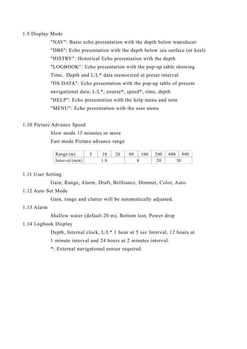
8004002001004020105Range (m)Interval (min) 1.8 8 20 30
1.9 Display Mode
NAV : Basic echo presentation with the depth below transducer
DBS : Echo presentation with the depth below sea surface (or keel)
HISTRY : Historical Echo presentation with the depth
LOGBOOK : Echo presentation with the pop-up table showing
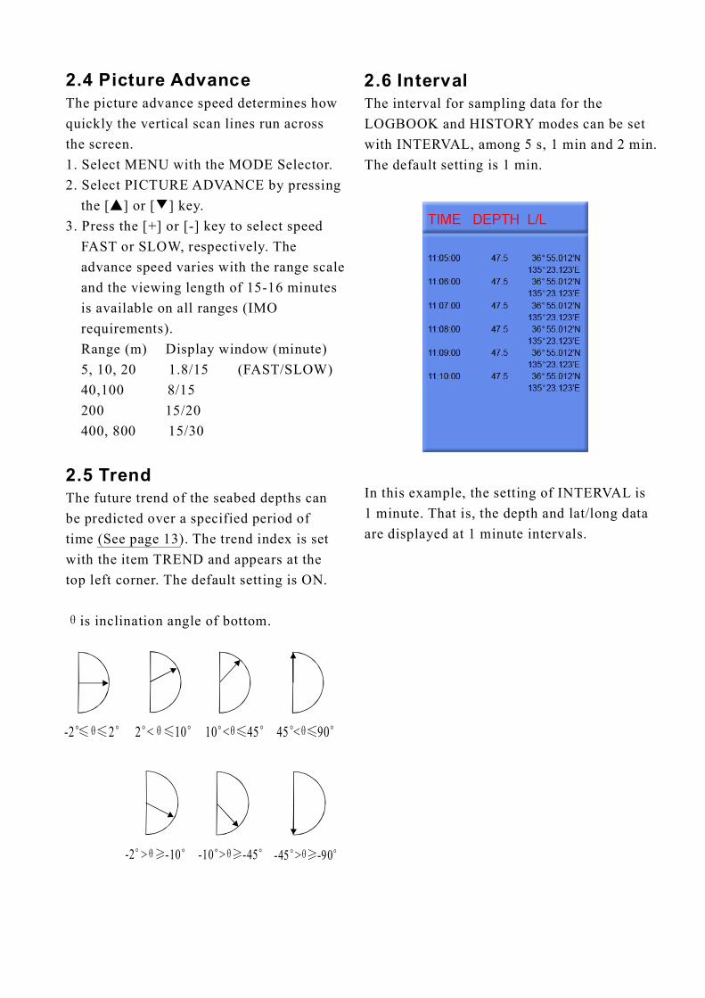
Time, Depth and L/L* data memorized at preset interval
OS DATA : Echo presentation with the pop-up table of present
navigational data; L/L*, course*, speed*, time, depth
HELP : Echo presentation with the help menu and note
MENU : Echo presentation with the user menu
1.10 Picture Advance Speed
Slow mode 15 minutes or more
Fast mode Picture advance range
1.11 User Setting
Gain, Range, Alarm, Draft, Brilliance, Dimmer, Color, Auto
1.12 Auto Set Mode
Gain, range and clutter will be automatically adjusted.
1.13 Alarm
Shallow water (default 20 m), Bottom lost, Power drop
1.14 Logbook Display
Depth, Internal clock, L/L* 1 hour at 5 sec Interval, 12 hours at
1 minute interval and 24 hours at 2 minutes interval.
*: External navigational sensor required.
" "
" "
" "
" "
" "
" "
" "

2.TRANSCEIVER CHARACTERISTICS (BUILT IN DISPLAY UNIT)
3.DIGITAL DEPTH INDICATOR
4.TRANSDUCER TYPE AND BEAMWIDTH
5.INTERFACE
2.1 Transmit Frequency 50 kHz or 200 kHz
2.2 Output Power 600 Wrms
3.1 Display 10.4-inch monochrome LCD
3.2 Depth Indication
**.* m (less than 100m)
**** m (100 m or more)
3.3 Power supply 24 VDC, 150mA
3.4 Coating color Panel: N3.0, Chassis: 2.5GY5/1.5
3.5 Waterproofing IPX5
4.1 50B-6B (50 kHz): 35
4.2 200B-8B (200 kHz): 6
5.1 Serial Input Data IEC61162-1, current loop; 1 port
RMA: L/L, ground track speed, Track
RMC: L/L(GPS), ground track speed, Track, Time
GLL: L/L
GGA: L/L
VTG: Ground track speed,
Track (True/Magnetic selected on menu)
ZDA: Time
5.2 Serial Output Data IEC61162-1, output period:1 sec.;3 outputs/1 port
SDDPT: Depth (m), Draft (m)
SDDBT: Depth (ft, m, fa) below transducer
SDDBS: Depth (ft, m, fa) below sea surface
°
°

5.3 Serial I/O Data RS-232C, 1 port
Output Depth, clock, L/L, ship s speed, course
SP - 3 E2366S01Q
Input Control command for PC
5.4 Alarm (Depth, Power) Contact closure signal, normal open or normal close,
250 VAC/ 200 VDC, 3A max.
24 VDC (-10%, +30%): 20W or 100-115/200-230 VAC,
1 phase, 50/60Hz: 20VA.
7.1 Temperature -15 to +55
7.2 Relative Humidity 93% or less at 40
7.3 Waterproofing Display Unit: IEC IPX5
Distribution Box: IEC IPX2
Matching Box: IEC IPX2
7.4 EMC Emission IEC 60945 Ver.3
7.5 Category of Equipment Units
Display Unit protected from the weather
Distribution Box protected from the weather
Matching Box protected from the weather
Transducer Submerged area
8.1 Display Unit Panel: N3.0, Chassis: 2.5GY5/1.5
8.2 Distribution Box/ Matching Box
2.5GY5/1.5
6.POWER SUPPLY
7.ENVIRONMENTAL CONDITION
8.COATING COLOR
℃ ℃
℃
'

1.1 Control DescriptionAll operation of the KES-700 is carried out with the controls on the front panel of the
display unit. Rotary controls respond immediately to your command but some touch keys
require the successive operation.
Adjusts display brillianceand tone.
Adjusts drafts
1. Raises or lowers setting2.Sets condition on menu.3.Selects page on Text display, etc.
Selects display range.
Selects display mode.
Adjusts panel dimmer
Turns automatic modeon or off. (Gain, rangeand clutter automaticallyadjusted.)
Sets alarms or mutesaudible alarms.
Selects presentation color.
Selects item on menu.
Selects display gain.
Turns power on or off.
DRAFT MUTEALARM
DIM BRILL
AUTO COLOR
RANGE
1
23
4 567
8
GAIN
MODE

1.2 Indications, Markers
Display mdoe
Gain setting
Range setting
Auto mode
Transducer in use (When usingtransducer switch box.)
Alarm settingRange scale
Depth
Depth unit
Explanation of depth(Below transducer, or below surface)
1.3
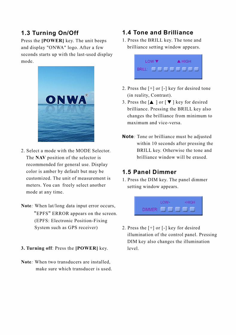
" " logo. After a fewseconds
" "
Turning On/OffPress the key. The unit beepsand display ONWA
starts up with the last-used displaymode.
When lat/long data input error occurs,EPFS ERROR appears on the screen.(EPFS: Electronic Position-FixingSystem such as GPS receiver)
Press the key.
[POWER]
Note
[POWER]
2. Select a mode with the MODE Selector.The position of the selector isrecommended for general use. Displaycolor is amber by default but may becustomized. The unit of measurement ismeters. You can freely select anothermode at any time.
:
When two transducers are installed,make sure which transducer is used.
NAV
3. Turning off
Note:
:
1.4 Tone and Brilliance
1.5 Panel Dimmer
1. Press the BRILL key. The tone andbrilliance setting window appears.
2. Press the [+] or [-] key for desired tone(in reality, Contrast).
3. Press the [ ] or [ ] key for desiredbrilliance. Pressing the BRILL key alsochanges the brilliance from minimum tomaximum and vice-versa.
Tone or brilliance must be adjustedwithin 10 seconds after pressing theBRILL key. Otherwise the tone andbrilliance window will be erased.
1. Press the DIM key. The panel dimmersetting window appears.
2. Press the [+] or [-] key for desiredillumination of the control panel. PressingDIM key also changes the illuminationlevel.
Note:
▲
▲
1.6 Display ModeThe Mode Selector choose the display modeamong NAV, DBS (depth below surface),HISTORY, LOGBOOK, OS DATA, HELPand MENU.
The depth from the transducer to the seabed(bottom clearance) is shown on the screen.Note BELOW TRANSDUCER appearsat the bottom of the screen in this mode.
Default is,Color: AmberRange: Automatic range switchingWindow: 15 minutesShallow depth alarm: 20 m
These parameters can be customizedto your preference and the last setting is usedat a next switch-on. This is true on all othermodes.
The Depth Below Surface mode provides adraft-adjusted depth reading and will beuseful inreferencing to the nautical chart.The draft should be adjusted by the DRAFTkey according to the actual draft value. Ifyou find any difficulty to check for the draftvalue, use the NAV mode.
When the DBS mode is selected, the messageConfirm and set ship s draft to use DBSmode appears. Confirm ship's draft and setit by referring to section 1.12.
1.6.1 NAV mode
NOTE
1.6.2 DBS mode
:
" "
""
BELOW KEEL (when the draft setting is-10.0 to -0.1) or BELOW SURFACE (whenthe draft setting is 0 to 30.0) appears at thebottom of the display and the draft valueappears at the upper right-hand corner in theDBS mode.
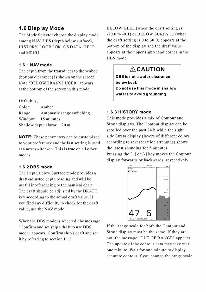
This mode provides a mix of Contour andStrata displays. The Contour display can bescrolled over the past 24 h while the rightside Strata display (layers of different colorsaccording to reverberation strengths) showsthe latest sounding for 5 minutes.Pressing the [+] or [-] key moves the Contourdisplay forwards or backwards, respectively.
If the range scale for both the Contour andStrata display must be the same. If they arenot, the message OUT OF RANGE appears.The update of the contour data may take max.one minute. Wait for one minute to displayaccurate contour if you change the range scale.
1.6.3 HISTORY mode
" "
CAUTION!DBS is not a water clearancebelow keel.Do not use this mode in shallowwaters to avoid grounding.

1.6.4 LOGBOOK mode
The LOGBOOK shows time, depth andown ship position in tabular form in apop-up window. The logging is selectedwith the INTERVAL option on the menuamong 5 s, 1 min and 2 min.(See section 2.6.)
There are 60 pages and the total memorycapacity is 720 points. Page 60/60 is thelatest data and 1/60 is the oldest data.Pressing [-] or [+] key changes the pages.
There are two kinds of OS DATA displays:DATA 1 and DATA 2, as selected on thesystem menu. DATA 1 is the default setting,and it is shown in the figure above.The DATA 2 display is as below.
When lat/long data input error occursin the DATA 1 mode, .EPFS. ERROR appearson the screen. (EPFS: Electronic Position-Fixing System such as GPS receiver)
Note:
1.6.5 OS DATA mode
This display mode indicates own shipposition, GPS-derived course and speed,and time and depth in digital form. You canread the data of your particular interest inlarge characters. The screen continues todisplay the sounding data in the background.Part of graphical indication is visible to theright of data slips.
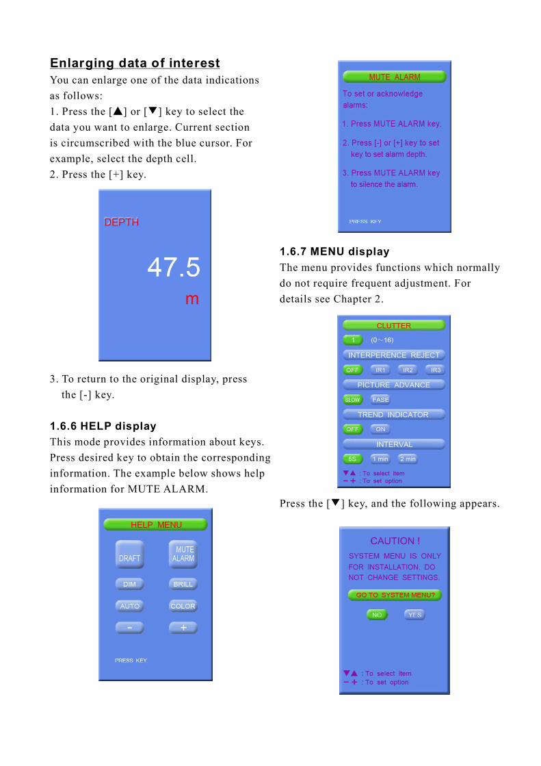
Enlarging data of interestYou can enlarge one of the data indicationsas follows:1. Press the [ ] or [ ] key to select thedata you want to enlarge. Current sectionis circumscribed with the blue cursor. Forexample, select the depth cell.2. Press the [+] key.
▲ ▼
3. To return to the original display, pressthe [-] key.
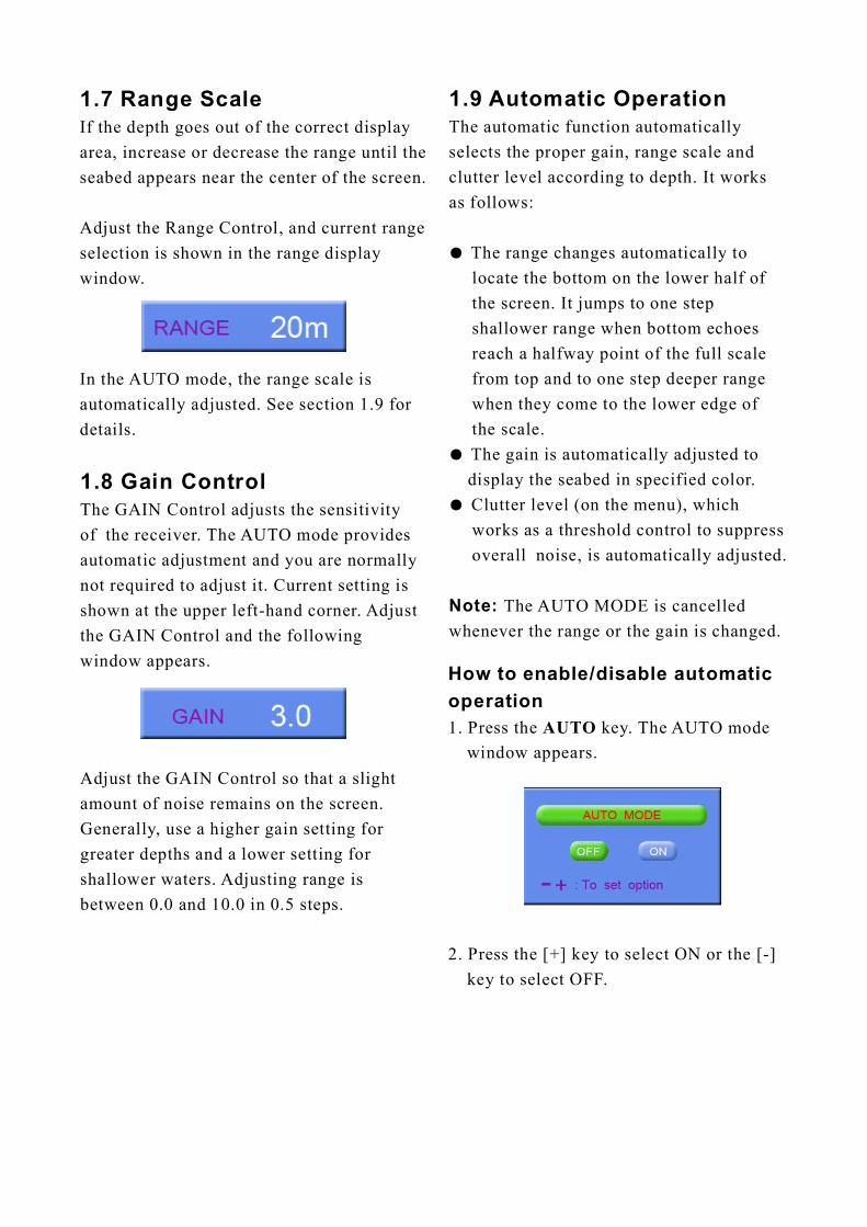
This mode provides information about keys.Press desired key to obtain the correspondinginformation. The example below shows helpinformation for MUTE ALARM.
1.6.6 HELP display
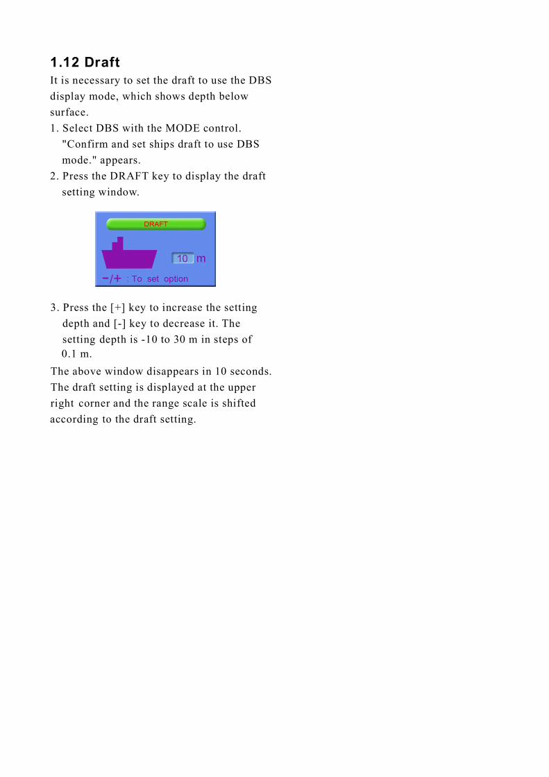
1.6.7 MENU displayThe menu provides functions which normallydo not require frequent adjustment. Fordetails see Chapter 2.
Press the [ key, and the following appears.▼]
1.8 Gain ControlThe GAIN Control adjusts the sensitivityof the receiver. The AUTO mode providesautomatic adjustment and you are normallynot required to adjust it. Current setting isshown at the upper left-hand corner. Adjustthe GAIN Control and the followingwindow appears.
Adjust the GAIN Control so that a slightamount of noise remains on the screen.Generally, use a higher gain setting forgreater depths and a lower setting forshallower waters. Adjusting range isbetween 0.0 and 10.0 in 0.5 steps.
1.9 Automatic OperationThe automatic function automaticallyselects the proper gain, range scale andclutter level according to depth. It worksas follows:
● The range changes automatically tolocate the bottom on the lower half ofthe screen. It jumps to one stepshallower range when bottom echoesreach a halfway point of the full scalefrom top and to one step deeper rangewhen they come to the lower edge ofthe scale.
● The gain is automatically adjusted todisplay the seabed in specified color.
● Clutter level (on the menu), whichworks as a threshold control to suppressoverall noise, is automatically adjusted.
Note: The AUTO MODE is cancelledwhenever the range or the gain is changed.
1. Press the key. The AUTO modewindow appears.
2. Press the [+] key to select ON or the [-]key to select OFF.
How to enable/disable automaticoperation
AUTO
1.7 Range ScaleIf the depth goes out of the correct displayarea, increase or decrease the range until theseabed appears near the center of the screen.
Adjust the Range Control, and current rangeselection is shown in the range displaywindow.
In the AUTO mode, the range scale isautomatically adjusted. See section 1.9 fordetails.

Monochrome (amber) is the default setting.The Strata display contains multiple colorsdepending on the reflectivity fromunderwater objects of the sounding pulses.Red is strongest, followed by brown, orange,yellow, blue, and light blue.
1.11 Shallow Depth AlarmThe shallow depth alarm sounds when theseabed is shallower than the preset depth.The default in the NAV position is 20 m.You can adjust the alarm depth as below:
Activating/deactivating the alarm1. Press the MUTE ALARM key to displaythe depth alarm setting window.
2. Press the [+] or [-] key to change settingdepth. The setting is shown digitally atthe top of the screen and graphically keythe depth alarm line.
When the alarm is activated, the message"SHALLOW DEPTH ALARM" is displayedat the center on the screen.
Note: When the draft setting is 10.0 to–
–0.1 in the DBS mode, the shallow depthalarm setting will show a minus value. Atthis time, the alarm setting value indicationshows "****" and the alarm function isdisabled.
Acknowledging the alarmYou can silence the alarm by pressing theMUTE ALARM key. The message" "SHALLOW DEPTH ALARM moves toupper side of the screen.
1.10 Picture Colors1. Press the COLOR key. The followingwindow appears.
2. Press the [+] or [-] key to select a number,referring to the table below. (You can seethe result of your selection on the display.)
BackgroundMonochrome, 8 intensities1
23456789
Blue
Black
White
Blue
7 colors (Strata)
6 colors
Seabed Others marks
BlackWhite
Black
White
Red infil l
Red infil l
Red infil l
Yellow infil l
7 colors (Strata)
6 colors
6 colors
6 colors
6 colors6 colors
Yellow infil l
Yellow infil l
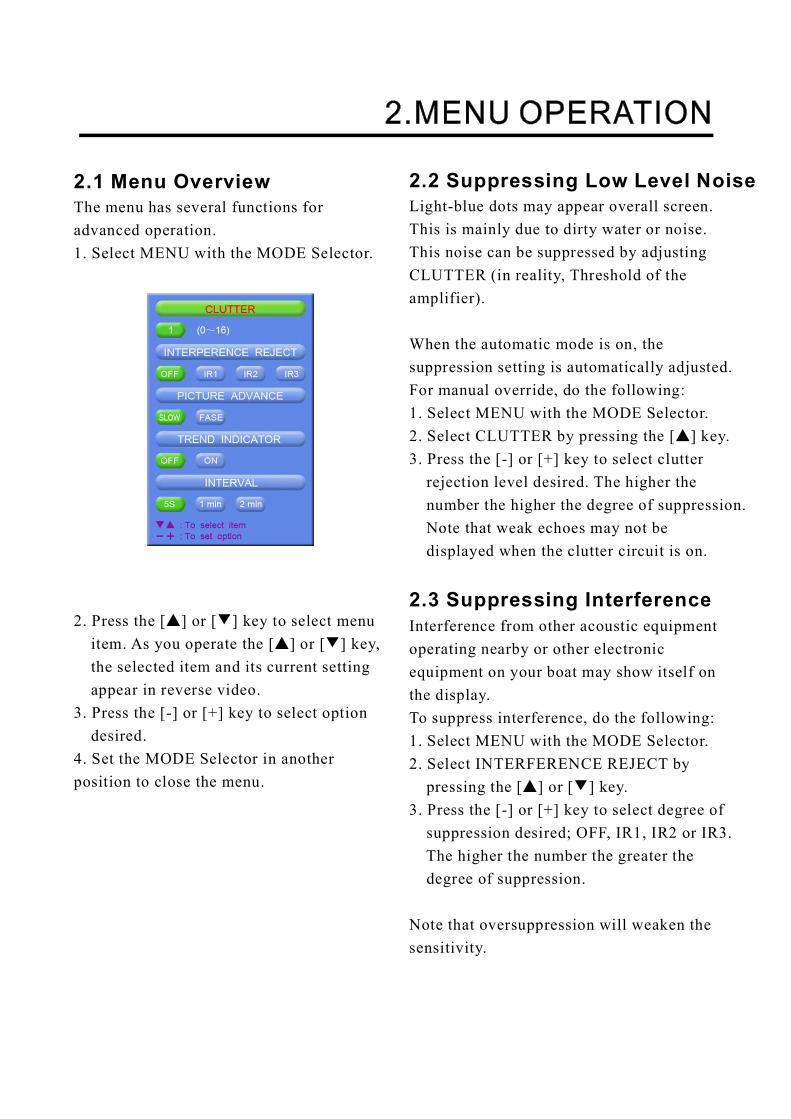
1.12 DraftIt is necessary to set the draft to use the DBSdisplay mode, which shows depth belowsurface.1. Select DBS with the MODE control.
Confirm and set ships draft to use DBS"mode. appears."
2. Press the DRAFT key to display the draftsetting window.
3. Press the [+] key to increase the settingdepth and [-] key to decrease it. Thesetting depth is -10 to 30 m in steps of
The above window disappears in 10 seconds.The draft setting is displayed at the upperright corner and the range scale is shiftedaccording to the draft setting.
0.1 m.
2.1 Menu OverviewThe menu has several functions foradvanced operation.1. Select MENU with the MODE Selector.
2. Press the [ ] or [ ] key to select menuitem. As you operate the [ ] or [ ] key,the selected item and its current settingappear in reverse video.
3. Press the [-] or [+] key to select optiondesired.
4. Set the MODE Selector in anotherposition to close the menu.
▲ ▼
▲ ▼
2.2 Suppressing Low Level Noise
2.3 Suppressing Interference
Light-blue dots may appear overall screen.This is mainly due to dirty water or noise.This noise can be suppressed by adjustingCLUTTER (in reality, Threshold of theamplifier).
When the automatic mode is on, thesuppression setting is automatically adjusted.For manual override, do the following:1. Select MENU with the MODE Selector.2. Select CLUTTER by pressing the [ ] key.3. Press the [-] or [+] key to select clutterrejection level desired. The higher thenumber the higher the degree of suppression.Note that weak echoes may not bedisplayed when the clutter circuit is on.
Interference from other acoustic equipmentoperating nearby or other electronicequipment on your boat may show itself onthe display.To suppress interference, do the following:1. Select MENU with the MODE Selector.2. Select INTERFERENCE REJECT bypressing the [ ] or [ ] key.
3. Press the [-] or [+] key to select degree ofsuppression desired; OFF, IR1, IR2 or IR3.The higher the number the greater thedegree of suppression.
Note that oversuppression will weaken thesensitivity.
▲
▲ ▼
The picture advance speed determines howquickly the vertical scan lines run acrossthe screen.1. Select MENU with the MODE Selector.2. Select PICTURE ADVANCE by pressingthe [ ] or [ ] key.
3. Press the [+] or [-] key to select speedFAST or SLOW, respectively. Theadvance speed varies with the range scaleand the viewing length of 15-16 minutesis available on all ranges (IMOrequirements).Range (m) Display window (minute)5, 10, 20 1.8/15 (FAST/SLOW)40,100 8/15200 15/20400, 800 15/30
The future trend of the seabed depths canbe predicted over a specified period oftime (See page 13). The trend index is setwith the item TREND and appears at thetop left corner. The default setting is ON.
is inclination angle of bottom.
2.4 Picture Advance
2.5 Trend
▲ ▼
θ
-2 2 2 < 10 10 < 45 45 < 90°≤θ≤ ° °θ≤ ° °θ≤ ° °θ≤ °
-2 > -10°θ≥ ° -10 > -45°θ≥ ° -45 > -90°θ≥ °
2.6 IntervalThe interval for sampling data for theLOGBOOK and HISTORY modes can be setwith INTERVAL, among 5 s, 1 min and 2 min.The default setting is 1 min.
In this example, the setting of INTERVAL is1 minute. That is, the depth and lat/long dataare displayed at 1 minute intervals.

3.1 System MenuThe system menu should be set just afterinstallation and is not always necessary tobe adjusted. If you change any items of thesystem menu or even if you open the systemmenu, the sounding picture will be cleared.There are three menus: 1,2,and 3.1. Select MENU with the MODE Selector.
2. Press the [ ] key several times to display▼
following window.
3. Select YES by pressing the [+] key.Confirmation messageARE YOU SURE? Appears." "
4. Press the [+] key again.
The system menu 1 appears.5. With the cursor selecting MENU SELECT,operate the [-] or [+] key to select systemmenu desired; 1, 2 or 3.
Press [+] at menu 1.Press [-] at menu 2.
▼▼
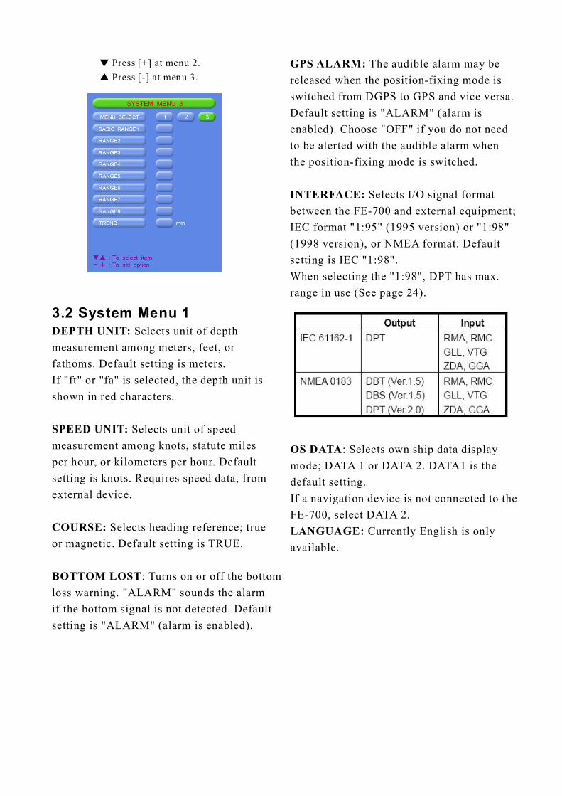
3.2 System Menu 1Selects unit of depth
measurement among meters, feet, orfathoms. Default setting is meters.If "ft" or "fa" is selected, the depth unit isshown in red characters.
Selects unit of speedmeasurement among knots, statute milesper hour, or kilometers per hour. Defaultsetting is knots. Requires speed data, fromexternal device.
Selects heading reference; trueor magnetic. Default setting is TRUE.
: Turns on or off the bottomloss warning. ALARM sounds the alarmif the bottom signal is not detected. Defaultsetting is ALARM (alarm is enabled).
DEPTH UNIT:
SPEED UNIT:
COURSE:
BOTTOM LOST" "
" "
OS DATA
LANGUAGE:
: Selects own ship data displaymode; DATA 1 or DATA 2. DATA1 is thedefault setting.If a navigation device is not connected to theFE-700, select DATA 2.
Currently English is onlyavailable.
GPS ALARM:
INTERFACE:
The audible alarm may bereleased when the position-fixing mode isswitched from DGPS to GPS and vice versa.Default setting is ALARM (alarm isenabled). Choose OFF if you do not needto be alerted with the audible alarm whenthe position-fixing mode is switched.
Selects I/O signal formatbetween the FE-700 and external equipment;IEC format 1:95 (1995 version) or 1:98(1998 version), or NMEA format. Defaultsetting is IEC 1:98 .When selecting the 1:98 , DPT has max.range in use (See page 24).
" "" "
" " " "
" "" "
Press [+] at menu 2.Press [-] at menu 3.
▼▼

TIME DIFFERENCE: Selects auto (UTC)or manual. Auto uses the time difference inZDA (IEC 61162-1). In manual, it isnecessary to enter the time difference inhours and minutes.
3.4 System Menu 3RANGE 1- 8:
Note:
Trend:
Activates or deactivatesspecific range scales. Default ranges are 5,10, 20, 40, 100, 200, 400, and 800 (meters).Setting area is 2 m to 800 m. The ranges 20mand 200 m can not be changed. They areessential in this equipment.
Ranges must be set in numerical order.For example, if range 1 is 5 m and range 3 is20m, range 2 should be between 6 and 19 m.
The trend index shows the probablebottom shape over a specified time within1-10 minutes. The default setting is 1 minute.Set the Trend time with [+] or [-].
3.3 System Menu 2TIME ADJUST: Selects internal clock orexternal clock (UTC clock). Default settingis INTERNAL.For INTERNAL, set current day, month,year, hour, minute and second with [+], [-],[ ] or [ ] key. The setting clock appearsand it counts upward.▼ ▲
If EXTERNAL is selected, the screenchanges as follows.

This chapter describes functions useful forimproving echo sounding performance.
4.1 Demonstration DisplayThe demonstration program shows how theFE-700 works.1. Turn off the equipment.2. Press the POWER Switch while pressingany key. Release the key when thefollowing EXTENSION MODE displayappears.
3. Press the [ ] key to select▼
DEMONSTRATION.
4.2 Transducer SettingAfter installing the equipment, set the transduceras follows.
Press the [+] key at the EXTENSION MODEdisplay. The following window appears.
1.
4. Press the [+] key to select ON.5. Reset the power. "DEMO" appears abovethe depth indication on the echo sounderdisplays and at the top right-hand corneron the data and graphic displays.
● To return to the normal operation, selectOFF at step 4 above. Restart the displayunit after waiting 5 s.
2. Set as follows by using [ ] or [ ] toselect an item and [+] or[-] to set option.
a) If only one transducer is installed, setXDR FORE field to 50 kHz or 200 kHz,according to actual installation. Leave theXDR AFT field as N/A.
▲ ▼
4.3 Bottom LevelIf the depth indication is unstable or theseabed cannot be displayed steadilynotwithstanding the adjustment of thecontrol panel, you may adjust thebottom echo level.
CAUTIONIf the level is set too low, the FE-700may not be able to distinguish thebottom from fish echo and thedepth indication may be unstableand if set to high the depthindication does not appear.
4.4 TVG LevelTVG (Time Varied Gain) compensates forpropagation attenuation of the ultrasonicwaves,reducing surface noise to provide asmooth display. The TVG lowers receiversensitivity at the time of pulse emissionand gradually increases it with time, thereby making objects of same reflectivity atdifferent depths appear at the same intensityor colors on the display. The TVG workingdepth is down to approximately 150 m onthe 200 kHz system and 350 m on the 50 kHzsystem. Outside this range the echoes fromthe seabed and fish schools are received infull level.There is no perceivable deterioration inperformance.1. Press the DRAFT key three times at theEXTENSION MODE display. The TVGSELECT window appears.
2. Set the TVG curve with [+] or [-]. Thedefault level is 5. Attenuation compensationcurve is at 20LogR curve.
3. Press the POWER switch to finish theadjustment. Wait 5 s, and then turn it onagain.
b) If two transducers are installed via theswitch box EX-8, set XDR FORE fieldand XDR AFT field to 50 kHz or 200 kHz,according to actual installation.
3. Reset the power.
The default settings in theTRANSDUCER SETTING window are N/A.At the first power-up after installation, thewindow appears to set transducer(s).
Note:
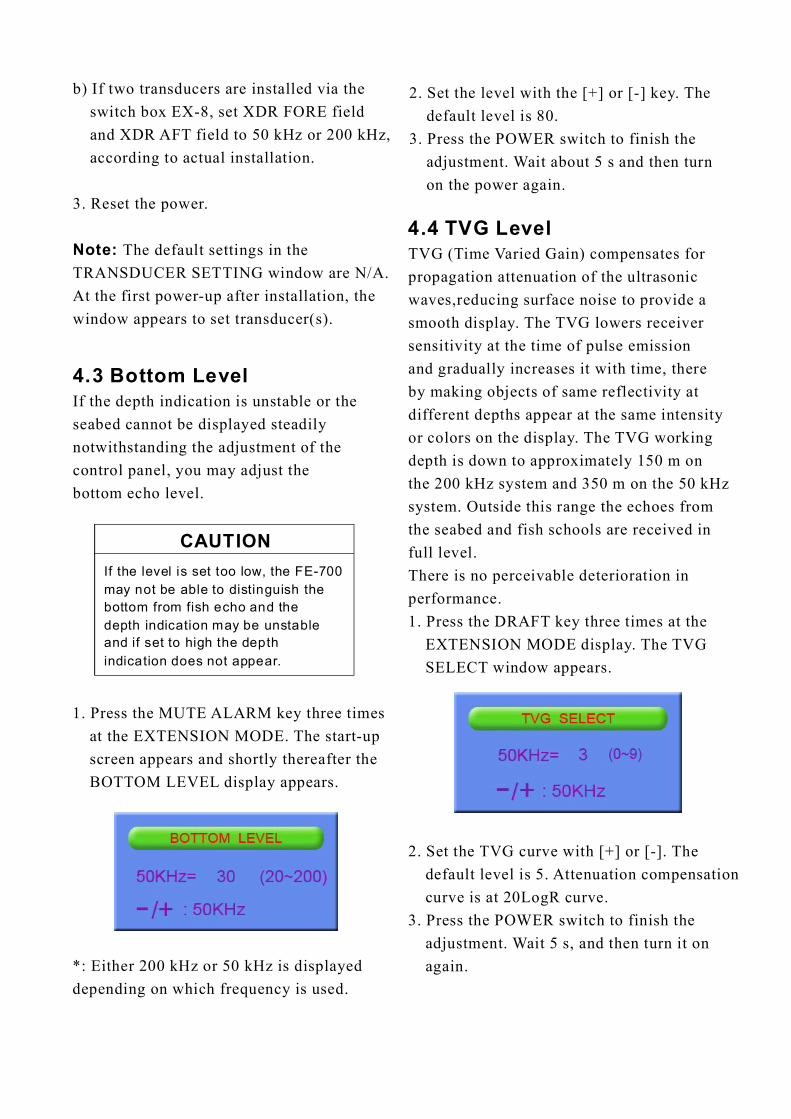
1. Press the MUTE ALARM key three timesat the EXTENSION MODE. The start-upscreen appears and shortly thereafter theBOTTOM LEVEL display appears.
*: Either 200 kHz or 50 kHz is displayeddepending on which frequency is used.
2. Set the level with the [+] or [-] key. Thedefault level is 80.
3. Press the POWER switch to finish theadjustment. Wait about 5 s and then turnon the power again.

4.5 Echo OffsetThe echo offset feature functions tocompensate for too weak or too strongecho level. If the onscreen echo levelappears to be too weak or too strongand the level cannot be adjustedsatisfactorily with the GAIN control,do the following to adjust echo level.
1. Press the DIM key three times atthe EXTENSION MODE display.The ECHO OFFSET screen appears.
2. Set the offset with [+] or [-]. The defaultvalue is 0.
3. Press the POWER switch to finish theadjustment. Wait about 5 s and then turnit on again.

5.1 Checking
5.2 Cleaning the Display Unit
Regular maintenance is essential for goodperformance. Checking the items listed inthe table below on a regular basis will keepthe equipment in good shape for years tocome.
Dust or dirt on the display unit should beremoved with a soft cloth. If desired awater-moistened cloth may be used. Do notuse chemical cleaners; they can removepaint and markings.
Item ActionCable run If conductors are
exposed, replacecable.
Power cable,transducer cableplug
If loosened, tighten.
Display unit ground If corroded, clean.
Ship's mains voltage If out of rating,correct problem.
5.3 Transducer Maintenance
5.4 Replacing the Fuse, Battery
Marine life on the transducer face will resultin a gradual decrease in sensitivity. Checkthe transducer face for cleanliness each timethe ship is dry-docked. Carefully remove anymarine life with a piece of wood or fine-gradesandpaper.
If a fuse blows, find the cause beforereplacing it. Use only designated fuses.Using the wrong fuse will damage the unitand void the warranty.
Three types of fuses are used in thedistribution box KES-700.
For Display Unit : 3 A x 1 pc (24 VDC)For Digital Depth Indicator: 0.5 A x 2 pcsFor AC input: 1 A x 2 pcs
The Digital Depth Indicator FE-720 usesone fuse of 1 A, which is inserted in thepositive line of interconnection cable.
A battery installed on a circuit board insidethe display unit preserves data when thepower is turned off. The life of the batteryis about three years. When the batteryvoltage is low, battery NG appears at theself-test. When this happens, contact yourdealer to request replacement of the battery.
“ ”
TYPE
Lithium Battery CR2450-F2 St2 000-133-495
Code Number
WARNINGDO not open the cover.There are no user-serviceable parts inside.Refer any repair work to a qualifiedtechnician.
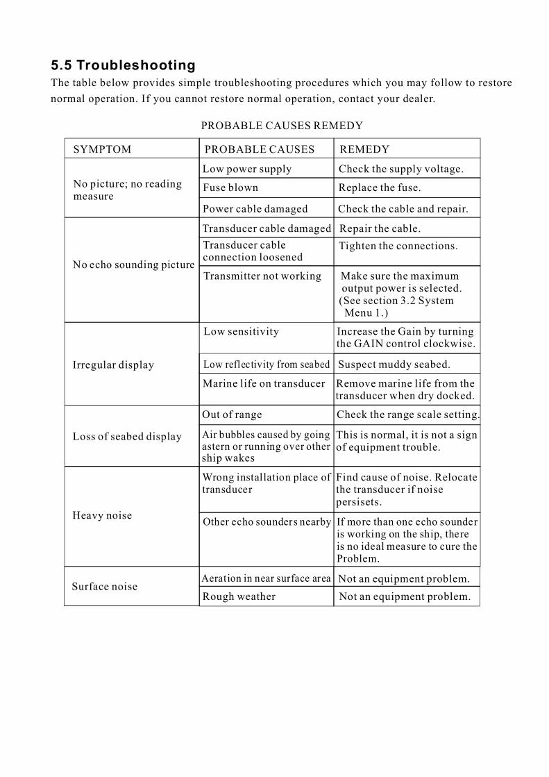
5.5 TroubleshootingThe table below provides simple troubleshooting procedures which you may follow to restorenormal operation. If you cannot restore normal operation, contact your dealer.
SYMPTOM
PROBABLE CAUSES REMEDY
PROBABLE CAUSES REMEDY
No picture; no readingmeasure
Low power supply Check the supply voltage.
Fuse blown Replace the fuse.
Power cable damaged Check the cable and repair.
No echo sounding picture
Transducer cable damaged Repair the cable.Transducer cableconnection loosened
Tighten the connections.
Transmitter not working Make sure the maximumoutput power is selected.(See section 3.2 SystemMenu 1.)
Irregular display
Low sensitivity Increase the Gain by turningthe GAIN control clockwise.
Low reflectivity from seabed Suspect muddy seabed.
Marine life on transducer Remove marine life from thetransducer when dry docked.
Out of range Check the range scale setting.
Loss of seabed display Air bubbles caused by goingastern or running over othership wakes
This is normal, it is not a signof equipment trouble.
Heavy noise
Find cause of noise. Relocatethe transducer if noisepersisets.
Wrong installation place oftransducer
Other echo sounders nearby If more than one echo sounderis working on the ship, thereis no ideal measure to cure theProblem.
Surface noiseAeration in near surface area Not an equipment problem.Rough weather Not an equipment problem.
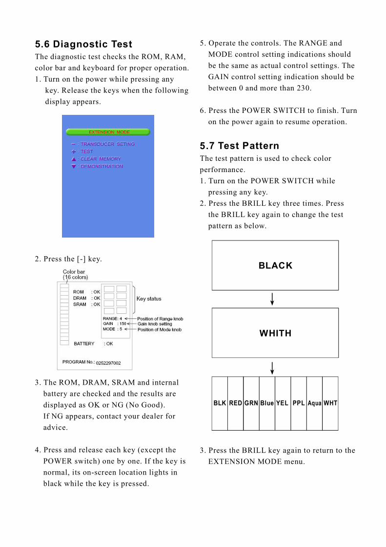
5.6 Diagnostic TestThe diagnostic test checks the ROM, RAM,color bar and keyboard for proper operation.1. Turn on the power while pressing any
key. Release the keys when the followingdisplay appears.
2. Press the [-] key.
3. The ROM, DRAM, SRAM and internalbattery are checked and the results aredisplayed as OK or NG (No Good).If NG appears, contact your dealer foradvice.
4. Press and release each key (except thePOWER switch) one by one. If the key isnormal, its on-screen location lights inblack while the key is pressed.
5. Operate the controls. The RANGE andMODE control setting indications shouldbe the same as actual control settings. TheGAIN control setting indication should bebetween 0 and more than 230.
6. Press the POWER SWITCH to finish. Turnon the power again to resume operation.
The test pattern is used to check colorperformance.1. Turn on the POWER SWITCH whilepressing any key.
2. Press the BRILL key three times. Pressthe BRILL key again to change the testpattern as below.
3. Press the BRILL key again to return to theEXTENSION MODE menu.
5.7 Test Pattern
↓
↓
BLK RED GRN Blue YEL PPL Aqua WHT
BLACK
WHITH
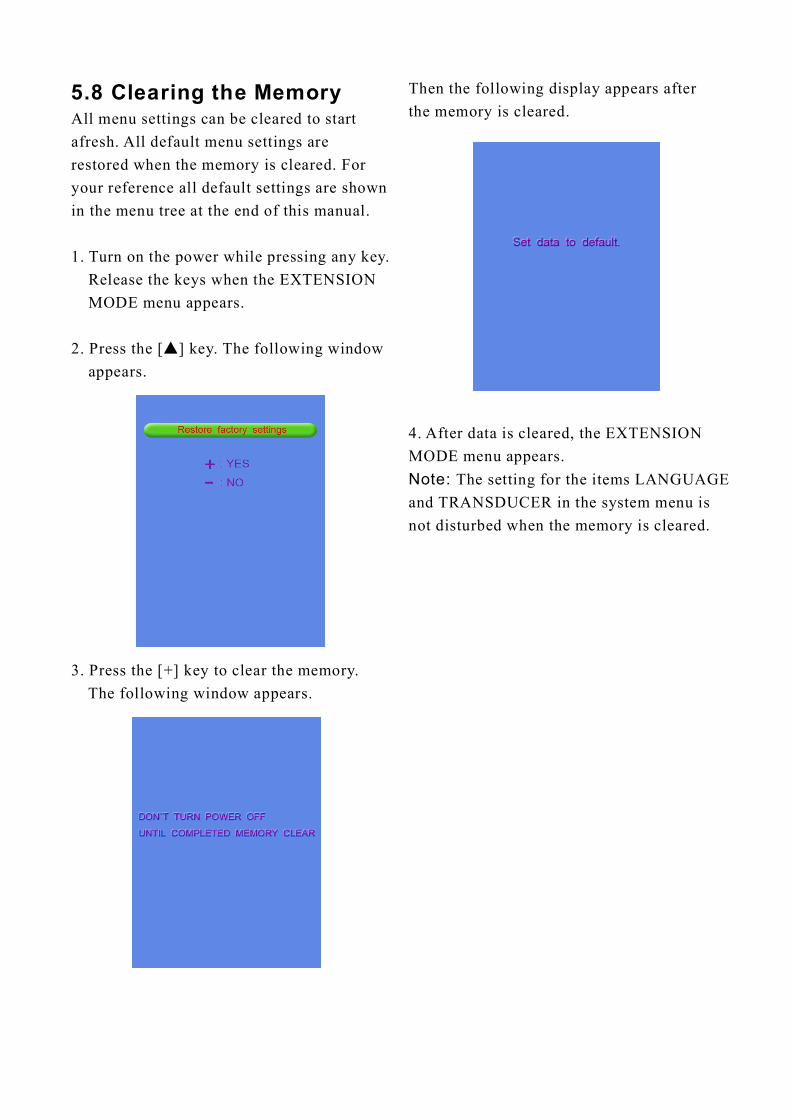
5.8 Clearing the MemoryAll menu settings can be cleared to startafresh. All default menu settings arerestored when the memory is cleared. Foryour reference all default settings are shownin the menu tree at the end of this manual.
1. Turn on the power while pressing any key.Release the keys when the EXTENSIONMODE menu appears.
2. Press the [ ] key. The following windowappears.
▲
3. Press the [+] key to clear the memory.The following window appears.
Then the following display appears afterthe memory is cleared.
4. After data is cleared, the EXTENSIONMODE menu appears.
The setting for the items LANGUAGEand TRANSDUCER in the system menu isnot disturbed when the memory is cleared.
Note:
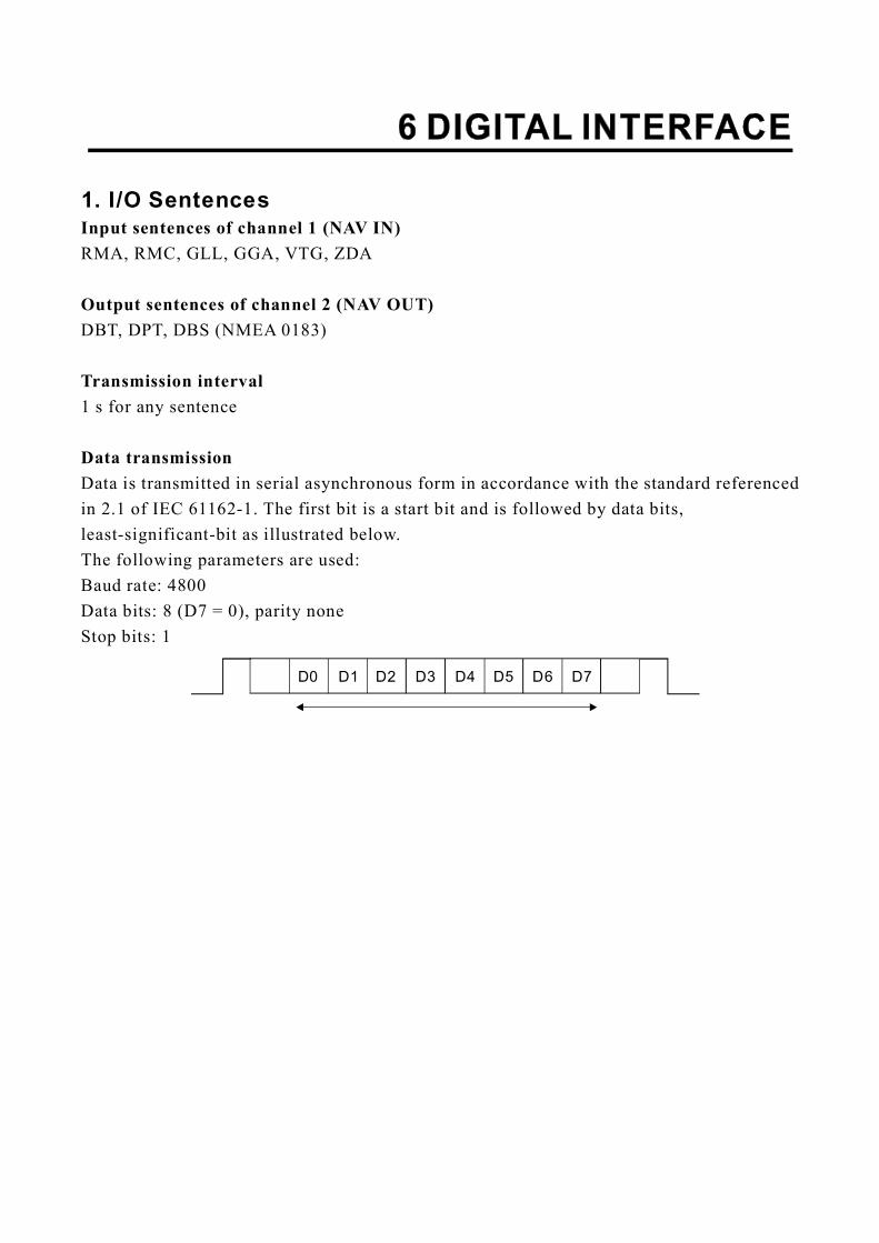
1. I/O Sentences
RMA, RMC, GLL, GGA, VTG, ZDA
DBT, DPT, DBS (NMEA 0183)
1 s for any sentence
Data is transmitted in serial asynchronous form in accordance with the standard referencedin 2.1 of IEC 61162-1. The first bit is a start bit and is followed by data bits,least-significant-bit as illustrated below.The following parameters are used:Baud rate: 4800Data bits: 8 (D7 = 0), parity noneStop bits: 1
Input sentences of channel 1 (NAV IN)
Output sentences of channel 2 (NAV OUT)
Transmission interval
Data transmission
D0 D1 D2 D3 D4 D5 D6 D7
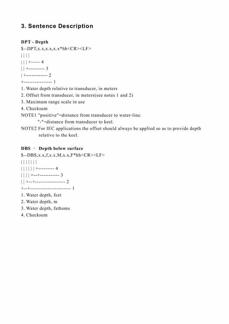
3. Sentence Description
$--DPT,x.x,x.x,x.x*hh<CR><LF>| | | || | | +----- 4| | +--------- 3| +------------ 2+---------------- 11. Water depth relative to transducer, in meters2. Offset from transducer, in meters(see notes 1 and 2)3. Maximum range scale in use4. ChecksumNOTE1 "positive"=distance from to water-line.
"-"=distance from transducer to keel.NOTE2 For IEC applications the offset should always be applied so as to provide depth
relative to the keel.
$--DBS,x.x,f,x.x,M,x.x,F*hh<CR><LF>| | | | | | || | | | | | +--------- 4| | | | +--+----------- 3| | +--+----------------- 2+--+----------------------- 11. Water depth, feet2. Water depth, m3. Water depth, fathoms4. Checksum
DPT - Depth
DBS Depth below surface
transducer
–
