keyestudio mega 2560 r3 development board datasheetkeyestudio 1 keyestudiomega2560r3board...
TRANSCRIPT

keyestudio
www.keyestudio.com 1
Keyestudio MEGA 2560 R3 Board
Introduction:Keyestudio Mega 2560 R3 is a microcontroller board based on the
ATMEGA2560-16AU , fully compatible with ARDUINO MEGA 2560 REV3.
It has 54 digital input/output pins (of which 15 can be used as PWM outputs), 16
analog inputs, 4 UARTs (hardware serial ports), a 16 MHz crystal oscillator, a USB
connection, a power jack, 2 ICSP headers, and a reset button.
It contains everything needed to support the microcontroller. With its bootloader,
program can be downloaded directly with USB and you don’t need to use other
external programmer.
Just simply connect it to a computer with a USB cable or power it with a AC-to-DC
adapter or battery to get started.
The Mega 2560 board is compatible with most shields designed for the Uno.
The 2560 R3 differs from all preceding boards in that it does not use the FTDI
keyestudio
www.keyestudio.com 2
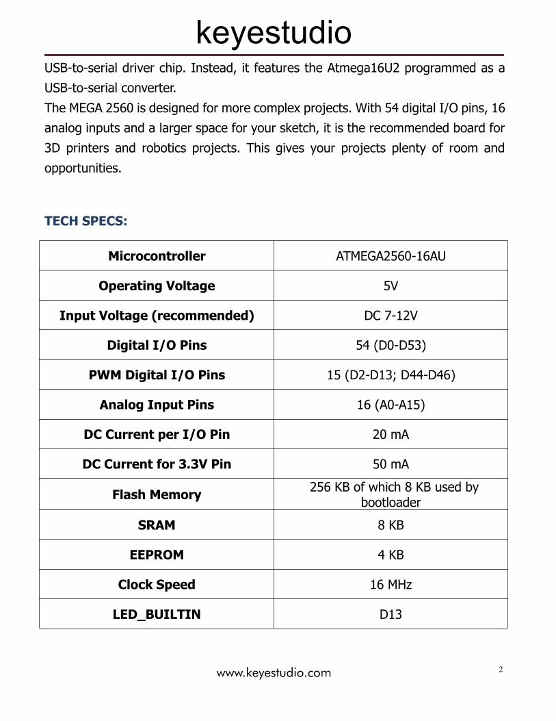
USB-to-serial driver chip. Instead, it features the Atmega16U2 programmed as a
USB-to-serial converter.
The MEGA 2560 is designed for more complex projects. With 54 digital I/O pins, 16
analog inputs and a larger space for your sketch, it is the recommended board for
3D printers and robotics projects. This gives your projects plenty of room and
opportunities.
TECH SPECS:
Microcontroller ATMEGA2560-16AU
Operating Voltage 5V
Input Voltage (recommended) DC 7-12V
Digital I/O Pins 54 (D0-D53)
PWM Digital I/O Pins 15 (D2-D13; D44-D46)
Analog Input Pins 16 (A0-A15)
DC Current per I/O Pin 20 mA
DC Current for 3.3V Pin 50 mA
Flash Memory 256 KB of which 8 KB used bybootloader
SRAM 8 KB
EEPROM 4 KB
Clock Speed 16 MHz
LED_BUILTIN D13

keyestudio
www.keyestudio.com 3
Dimensions:
Element and Pin Interfaces:Here is an explanation of what every element and interface of the board does:

keyestudio
www.keyestudio.com 4
Digital I/OArduino MEGA has 54 digital input/output pins (of which 15 can be used as
PWM outputs). These pins can be configured as digital input pin to read
the logic value (0 or 1). Or used as digital output pin to drive different
modules like LED, relay, etc.
Using pinMode(), digitalWrite(), and digitalRead() functions.
GNDGround pins
AREFReference voltage (0-5V) for analog inputs. Used with analogReference().
Configures the reference voltage used for analog input (i.e. the value used
as the top of the input range).
SDAIIC communication pin
SCLIIC communication pin
ICSP (In-Circuit Serial Programming) Headerthe AVR, an Arduino micro-program header consisting of MOSI, MISO,
SCK, RESET, VCC, and GND. Connected to the ATMEGA16U2-MU.
When connecting to PC, program the firmware to ATMEGA16U2-MU.
USB ConnectionArduino board can be powered via USB connector.
All you needed to do is connecting the USB port to PC using a USB cable.

keyestudio
www.keyestudio.com 5
D13 LEDThere is a built-in LED driven by digital pin 13. When the pin is HIGH value,
the LED is on, when the pin is LOW, it's off.
ATMEGA 16U2-MUUSB to serial chip, can convert the USB signal into serial port signal.
TX LEDOnboard you can find the label: TX (transmit)
When Arduino board communicates via serial port, send the message, TX
led flashes.
RX LEDOnboard you can find the label: RX(receive )
When Arduino board communicates via serial port, receive the message,
RX led flashes.
Crystal OscillatorHow does Arduino calculate time? by using a crystal oscillator.
The number printed on the top of the Arduino crystal is 16.000H9H. It tells
us that the frequency is 16,000,000 Hertz or 16MHz.
Voltage RegulatorTo control the voltage provided to the Arduino board, as well as to stabilize
the DC voltage used by the processor and other components.
Convert an external input DC7-12V voltage into DC 5V, then switch DC 5V
to the processor and other components.
DC Power JackArduino board can be supplied with an external power DC7-12V from the
DC power jack.

keyestudio
www.keyestudio.com 6
IOREFThis pin on the board provides the voltage reference with which the
microcontroller operates. A properly configured shield can read the IOREF
pin voltage and select the appropriate power source or enable voltage
translators on the outputs for working with the 5V or 3.3V.
RESET HeaderConnect an external button to reset the board. The function is the same as
reset button.
Power Pin 3V3A 3.3 volt supply generated by the on-board regulator. Maximum current
draw is 50 mA.
Power Pin 5VProvides 5V output voltage
VinYou can supply an external power input DC7-12V through this pin to
Arduino board.
Analog PinsOnboard has 16 analog inputs, labeled A0 to A15.
RESET ButtonYou can reset your Arduino board, for example, start the program from the
initial status. You can use the RESET button.
ICSP (In-Circuit Serial Programming) Headerthe AVR, an Arduino micro-program header consisting of MOSI, MISO,
SCK, RESET, VCC, and GND.
It is often called the SPI (serial peripheral interface) and can be considered

keyestudio
www.keyestudio.com 7
an "extension" of the output. In fact, slave the output devices to the SPI
bus host.
When connecting to PC, program the firmware to ATMEGA2560-16AU.
MicrocontrollerEach Arduino board has its own microcontroller. You can regard it as the
brain of your board.
The main IC (integrated circuit) on the Arduino is slightly different from the
panel pair. Microcontrollers are usually from ATMEL. Before you load a new
program on the Arduino IDE, you must know what IC is on your board.
This information can be checked at the top of IC.
Power LED IndicatorPowering the Arduino, LED on means that your circuit board is correctly
powered on. If LED is off, connection is wrong.
Specialized Functions of Some Pins:
Serial Communication: D0 (RX0) and D1 (TX1); Serial 1: D19 (RX1) andD18 (TX1); Serial 2: D17 (RX2) and D16 (TX2); Serial 3: D15 (RX3) and D14
(TX3).
Used to receive (RX) and transmit (TX) TTL serial data. Pins 0 and 1 are also
connected to the corresponding pins of the ATmega16U2 USB-to-TTL Serial
chip.
PWM Pins (Pulse-Width Modulation): D2 to D13, and D44 to D46.Provide 8-bit PWM output with the analogWrite() function.

keyestudio
www.keyestudio.com 8
External Interrupts: D2 (interrupt 0), D3 (interrupt 1), D18 (interrupt 5),D19 (interrupt 4), D20 (interrupt 3), and D21 (interrupt 2).
These pins can be configured to trigger an interrupt on a low level, a rising or
falling edge, or a change in level. See the attachInterrupt() function for details.
SPI communication: D53 (SS), D52 (SCK), D51 (MOSI), D50 (MISO).These pins support SPI communication using theSPI library. The SPI pins are
also broken out on the ICSP header, which is physically compatible with the
Arduino Uno.
IIC communication: D20 (SDA); D21 (SCL). Support TWI communicationusing the Wire library.
keyestudio
www.keyestudio.com 9
Warnings:
The Mega 2560 has a resettable polyfuse that protects your computer's USB
ports from shorts and overcurrent. If more than 500 mA is applied to the USB
port, the fuse will automatically break the connection until the short or overload
is removed.
Automatic (Software) Reset:
Rather than requiring a physical press of the reset button before an upload, the
Mega 2560 board is designed in a way that allows it to be reset by software
running on a connected computer.
The Mega 2560 board contains a trace that can be cut to disable the auto-reset.
The pads on either side of the trace can be soldered together to re-enable it.
It's labeled "RESET-EN". You may also be able to disable the auto-reset by
connecting a 110 ohm resistor from 5V to the reset line; see this forum
thread for details.
keyestudio
www.keyestudio.com 10
Detailed Use with ARDUINO Software as follows:
Step1 | Download the Arduino environment (IDE)
When you get the Mega 2560 development board, first you should install the
Arduino software and driver.
We usually use the Windows software Arduino 1.5.6 version. You can download it
from the link below:
https://www.arduino.cc/en/Main/OldSoftwareReleases#1.5.x
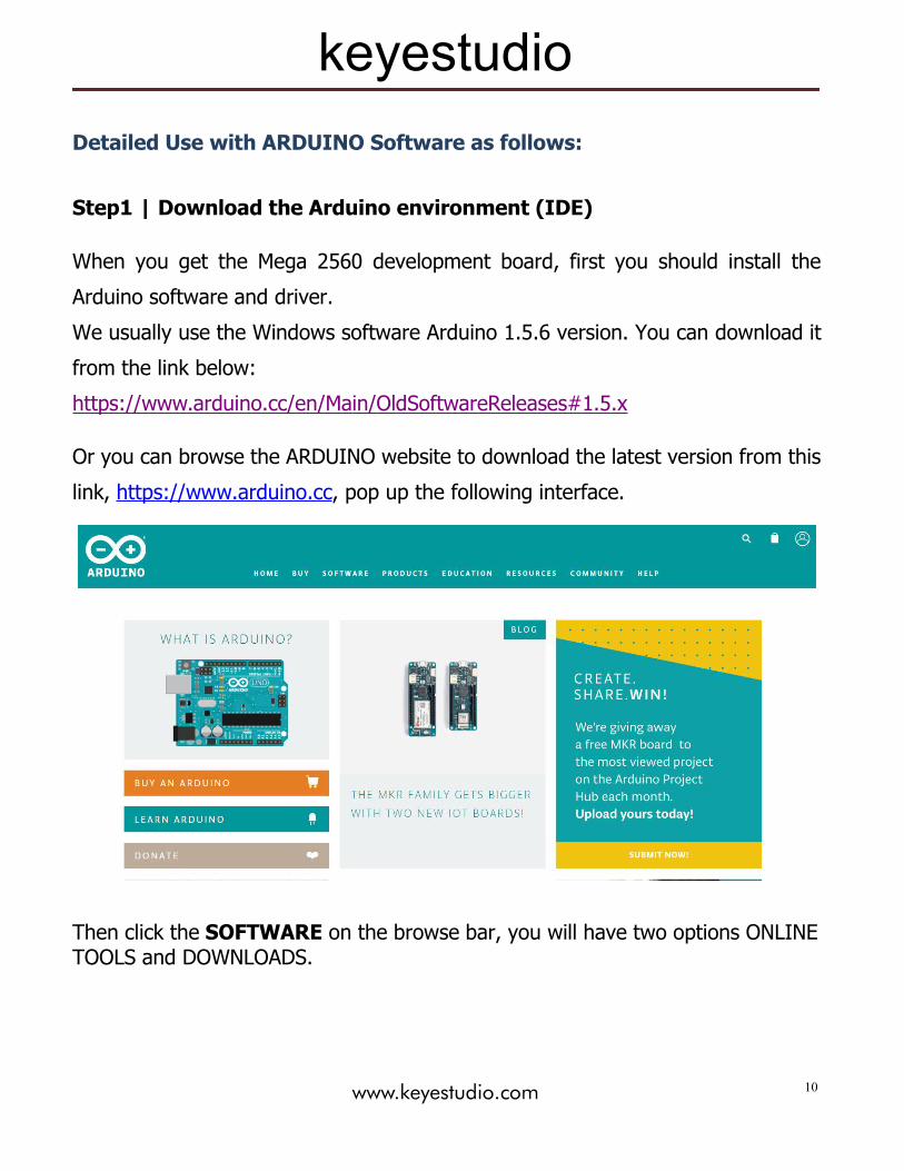
Or you can browse the ARDUINO website to download the latest version from this
link, https://www.arduino.cc, pop up the following interface.
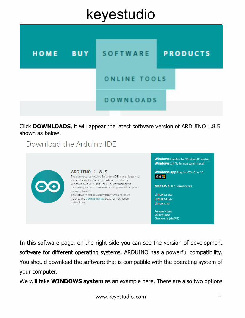
Then click the SOFTWARE on the browse bar, you will have two options ONLINETOOLS and DOWNLOADS.
keyestudio
www.keyestudio.com 11
Click DOWNLOADS, it will appear the latest software version of ARDUINO 1.8.5shown as below.
In this software page, on the right side you can see the version of development
software for different operating systems. ARDUINO has a powerful compatibility.
You should download the software that is compatible with the operating system of
your computer.
We will takeWINDOWS system as an example here. There are also two options

keyestudio
www.keyestudio.com 12
under Windows system, one is installed version, the other is non-installed version.
For simple installed version, first click Windows Installer, you will get the
following page.

keyestudio
www.keyestudio.com 13
This way you just need to click JUST DOWNLOAD, then click the downloaded file to
install it.
For non-installed version, first click Windows ZIP file, you will also get the pop-up
interface as the above figure.
Click JUST DOWNLOAD, and when the ZIP file is downloaded well to your
computer, you can directly unzip the file and click the icon of ARDUINO software to
start it.
Installing Arduino (Windows):Install Arduino with the exe. Installation package downloaded well.
Click “I Agree” to see the following interface.

keyestudio
www.keyestudio.com 14
Click “Next”. Pop up the interface below.

keyestudio
www.keyestudio.com 15
You can press Browse… to choose an installation path or directly type in the
directory you want. Then click “Install” to initiate installation.
Wait for the installing process, if appear the interface of Window Security, just
continue to click Install to finish the installation.

keyestudio
www.keyestudio.com 16
Installing Driver:
Next, we will introduce the driver installation of Mega 2560 development board.
The driver installation may have slight differences in different computer systems.
So in the following let’s move on to the driver installation in the WIN 7 system.
The Arduino folder contains both the Arduino program itself and the drivers that
allow the Arduino to be connected to your computer by a USB cable. Before we
launch the Arduino software, you are going to install the USB drivers.
Plug one end of your USB cable into the Arduino and the other into a USB socket
on your computer.
When you connect Mega 2560 board to your computer at the first time, right click
the icon of your “Computer” —>for “Properties”—> click the “Device manager”,
under “Other Devices”, you should see an icon for “Unknown device” with a little
yellow warning triangle next to it. This is your Arduino.

keyestudio
www.keyestudio.com 17
Then right-click on the device and select the top menu option (Update Driver
Software...) shown as the figure below.

keyestudio
www.keyestudio.com 18
It will then be prompted to either “Search Automatically for updated driver
software” or “Browse my computer for driver software”. Shown as below. In this
page, select “Browse my computer for driver software”.
After that, select the option to browse and navigate to the “drivers” folder ofArduino installation.

keyestudio
www.keyestudio.com 19
Click “Next” and you may get a security warning, if so, allow the software to beinstalled. Shown as below.

keyestudio
www.keyestudio.com 20
Installation completed, click “Close”.
Up to now, the driver is installed well. Then you can right click “Computer”
—>“Properties”—>“Device manager”, you should see the device shown below.

keyestudio
www.keyestudio.com 21
Introduction for Arduino IDE Toolbar:Double-click the icon of Arduino software downloaded well, you will get theinterface shown below.
(Note: if the Arduino software loads in the wrong language, you can change it in
the preferences dialog. See the environment page for details.)

keyestudio
www.keyestudio.com 22
The functions of each button on the Toolbar are listed below:
Verify/CompileCheck the code for errors
Upload
Upload the current Sketch to theArduino
NewCreate a new blank Sketch
OpenShow a list of Sketches
SaveSave the current Sketch
Serial Monitor
Display the serial data being sent fromthe Arduino

keyestudio
www.keyestudio.com 23
Step2| Connect the boardConnect the Mega 2560 board to your computer using the USB cable. The green
power LED should go on.
Step3| Select the Arduino BoardOpen the Arduino IDE, you’ll need to click the “Tools”, then select the Board that
corresponds to your Arduino.

keyestudio
www.keyestudio.com 24
Step4| Select your serial port
Select the serial device of the Arduino board from the Tools | Serial Port menu.This is likely to be COM3 or higher (COM1and COM2 are usually reserved for
hardware serial ports). To find out, you can disconnect your Arduino board and
re-open the menu; the entry that disappears should be the Arduino board.
Reconnect the board and select that serial port.
Here you should select COM 7 as below.
Note: to avoid errors, the COM Port should keep the same as the Ports shown onDevice Manager.

keyestudio
www.keyestudio.com 25

keyestudio
www.keyestudio.com 26
Step5|Upload the Program
Below is an example program for displaying the Hello World!
Copy and paste the code to the Arduino environment IDE.
///////////////////////////////////////////////////////////////////////////////////////////////int val;//define variable valint ledpin=13;// define digital pin13void setup(){Serial.begin(9600);// set the baud rate at 9600. When connected to a specific device, (e.g.bluetooth), the baud rate needs to be the same with the device.pinMode(ledpin,OUTPUT);// initialize digital pin 13 as output. When using I/O ports onan Arduino, this kind of set up is always needed.}void loop(){val=Serial.read();// read the instruction or character from PC to Arduino, and assign themto Val.if(val=='R')// determine if the instruction or character received is an “R”.{ // if it’s “R”,digitalWrite(ledpin,HIGH);// set the LED on digital pin 13 on.delay(500);digitalWrite(ledpin,LOW);// set the LED on digital pin 13 off.delay(500);Serial.println("Hello World!");// display“Hello World!”.}}///////////////////////////////////////////////////////////////////////////////////////////////

keyestudio
www.keyestudio.com 27
Then click verify button to check the errors. If compiling successfully, the message
"Done compiling." will appear in the status bar.
After that, click the “Upload” button to upload the code. Wait a few seconds - you
should see the RX and TX leds on the board flashing. If the upload is successful,
the message "Done uploading." will appear in the status bar. (Note: If you have an
Arduino Mini, NG, or other board, you'll need to physically present the reset button
on the board immediately before pressing the upload button.)

keyestudio
www.keyestudio.com 28
Step6|Open the Serial MonitorAfter that, click the serial monitor button to open the serial monitor.

keyestudio
www.keyestudio.com 29
Then set the baud rate as 9600, enter an “R” and click Send, you should see the TX
led on the board blink once, and then D13 led blink once, finally "Hello World!" is
showed on the monitor, the RX led blink once.

keyestudio
www.keyestudio.com 30
Other Links:
You might also want to look at:
the examples for using various sensors and actuators;
the reference for the Arduino language;
The text of the Arduino getting started guide is licensed under a Creative
Commons Attribution-ShareAlike 3.0 License. Code samples in the guide are
released into the public domain.
You can download the datasheet from the link:
https://drive.google.com/open?id=1eKufH3g5lYrfX7_Ew6CS9b-jQ1_RGtxV
Software Download:
https://drive.google.com/open?id=12D-JkXdNm03Qt4dlPQr3RP6OmgXqpvHc
Troubleshooting:
If you have problems, please see the troubleshooting suggestions.